EP0109329A2 - Mécanisme d'entraînement équilibré pour tête d'impression - Google Patents
Mécanisme d'entraînement équilibré pour tête d'impression Download PDFInfo
- Publication number
- EP0109329A2 EP0109329A2 EP83402116A EP83402116A EP0109329A2 EP 0109329 A2 EP0109329 A2 EP 0109329A2 EP 83402116 A EP83402116 A EP 83402116A EP 83402116 A EP83402116 A EP 83402116A EP 0109329 A2 EP0109329 A2 EP 0109329A2
- Authority
- EP
- European Patent Office
- Prior art keywords
- print head
- resonant frequency
- spring
- sinusoidal
- Prior art date
- Legal status (The legal status is an assumption and is not a legal conclusion. Google has not performed a legal analysis and makes no representation as to the accuracy of the status listed.)
- Withdrawn
Links
Images
Classifications
-
- B—PERFORMING OPERATIONS; TRANSPORTING
- B41—PRINTING; LINING MACHINES; TYPEWRITERS; STAMPS
- B41J—TYPEWRITERS; SELECTIVE PRINTING MECHANISMS, i.e. MECHANISMS PRINTING OTHERWISE THAN FROM A FORME; CORRECTION OF TYPOGRAPHICAL ERRORS
- B41J25/00—Actions or mechanisms not otherwise provided for
- B41J25/001—Mechanisms for bodily moving print heads or carriages parallel to the paper surface
- B41J25/006—Mechanisms for bodily moving print heads or carriages parallel to the paper surface for oscillating, e.g. page-width print heads provided with counter-balancing means or shock absorbers
-
- B—PERFORMING OPERATIONS; TRANSPORTING
- B41—PRINTING; LINING MACHINES; TYPEWRITERS; STAMPS
- B41J—TYPEWRITERS; SELECTIVE PRINTING MECHANISMS, i.e. MECHANISMS PRINTING OTHERWISE THAN FROM A FORME; CORRECTION OF TYPOGRAPHICAL ERRORS
- B41J19/00—Character- or line-spacing mechanisms
- B41J19/18—Character-spacing or back-spacing mechanisms; Carriage return or release devices therefor
- B41J19/20—Positive-feed character-spacing mechanisms
- B41J19/30—Electromagnetically-operated mechanisms
- B41J19/305—Linear drive mechanisms for carriage movement
-
- B—PERFORMING OPERATIONS; TRANSPORTING
- B41—PRINTING; LINING MACHINES; TYPEWRITERS; STAMPS
- B41J—TYPEWRITERS; SELECTIVE PRINTING MECHANISMS, i.e. MECHANISMS PRINTING OTHERWISE THAN FROM A FORME; CORRECTION OF TYPOGRAPHICAL ERRORS
- B41J2/00—Typewriters or selective printing mechanisms characterised by the printing or marking process for which they are designed
- B41J2/22—Typewriters or selective printing mechanisms characterised by the printing or marking process for which they are designed characterised by selective application of impact or pressure on a printing material or impression-transfer material
- B41J2/23—Typewriters or selective printing mechanisms characterised by the printing or marking process for which they are designed characterised by selective application of impact or pressure on a printing material or impression-transfer material using print wires
- B41J2/235—Print head assemblies
- B41J2/245—Print head assemblies line printer type
Definitions
- This invention relates generally to an improved print head drive system for a shuttle dot matrix type printer and, more particularly, to such a drive system in which the print head and drive mechanism have equal masses and are mounted on springs to provide a mechanically balanced system wherein the print head array oscillates or reciprocates with a sinusoidal motion at a' resonant frequency corresponding to that of the desired printing rate determined from throughput requirements and character geometry.
- U.S. Patent No. 4, 306, 497 there is disclosed an attempt to provide a dynamically balanced dot matrix printer wherein the print head is connected by E-shaped plate springs to a balancing mass which, in turn, is connected by similar springs to a base structure; furthermore, the print head is specifically driven at a frequency other than the mechanical resonant frequency of the system.
- the Hewlett Packard Company has announced a Model 2608A dot matrix line printer wherein print hammer assemblies are mounted on a core bar which is driven back and forth by a voice coil type linear motor, and wherein both the core bar and the linear motor housing are attached to the printer casting by stiff flexure springs; however, there;is no indication that the system is balanced by a counterweight or otherwise, or that the core bar is driven at the natural or resonant frequency of the system.
- the broad object of the invention is to provide an improved print head array drive system for a shuttle matrix printer wherein a resonant spring mass system is used in conjunction with a simple reciprocating drive device to obtain a large oscillatory displacement of the print head at a stable oscillating frequency.
- Another object of the invention is to provide such an improved drive mechanism wherein the print head and drive device form a balanced mass system which is driven to oscillate with sinusoidal motion at the system's natural or resonant frequency corresponding to a desired print rate.
- a more specific object of the invention is to provide such an improved drive mechanism wherein the print head includes the core of a linear motor which is energized by sinusoidal alternating current at the resonant frequency corresponding to the desired print rate, and wherein both the print head and the motor coil are mounted on leaf springs fixed to the frame of the printer.
- a still more specific object is to provide such an improved drive mechanism wherein the core comprises a permanent magnet, and wherein a counterweight is added to the coil to make the masses of the print head and coil equal.
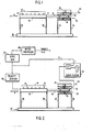
- FIGURE 1 is a schematic diagram illustrating the principle of operation of the preferred embodiment of the invention.
- a shuttle print head 10 comprises an array or plurality of printing elements 12 which are shown opposite a line of print 14 which, typically, would be on an incrementally driven section of paper backed by a striker bar or rigid backstop. During printing, the print head 10 is reciprocated or oscillated in the directions indicated by the arrow A.
- the printing elements when selectively energized impact the paper through an inked ribbon to produce printed indicia at equally spaced column locations on the record medium or paper.
- Print head 10 is fixed to an aluminum rod 16 which, in t'urn, is fixed to a permanent magnet 18 which forms the movable core or armature of a reciprocating linear drive motor 20 including a drive coil 22 which is energized by an alternating current signal 44 having a frequency equal to one of the above noted resonant frequencies corresponding to a desired print rate.
- a counterweight 26 is fixed to the coil 22 so that the mass of the coil and counterweight is equal to that of the print head array assembly including print head 10, rod 16 and permanent magnet 18.
- Print head 10 is supported by a pair of leaf springs 28 and 30 which are fixed to the frame 32 of the printing apparatus, and the print head drive coil 22 with counterweight 26 is also supported on a pair of leaf springs 34 and 36 fixed to the frame 32.
- Leaf springs 28, 30, 34 and 36 are identical, constrain the print head array and coil to roughly linear motion, and negate the need for the linear or rotary bearings of the prior art. There is only a slight pulling back of the print head from the paper as the print head increases in displacement from the rest position, but at all times the print head array remains substantially parallel to the paper. Such a spring configuration eliminates contact wear mechanisms, and with proper design the life of the springs can be very long.
- the springs are tailored so that their stiffness, when combined with the print head mass or the coil/counterweight mass, produces a resonant spring/mass system having a natural frequency which matches the required oscillating frequency of the print head array.
- FIGURE 2 is a schematic diagram illustrating the manner in which the preferred embodiment operates within a matrix printer. Corresponding elements in FIGURES 1 and 2 have the same reference numerals.
- the coil 22 Upon energizing the coil 22 with sinusoidal alternating current having a frequency equal to the preselected natural frequency of the system, the coil and permanent magnet 18 start to vibrate with oscillations of increasing amplitude. As the amplitude of the oscillations, i.e. the displacement of the print head array, reaches the desired level, a feedback system senses and holds the proper amplitude. As the losses take energy from the system and the amplitude tends to decay, the feedback system applies more energy to the coil to correct further losses, thereby.maintaining the sinusoidal motion with the desired amplitude.
- the system is balanced, whereby the print head array and coil 22 naturally vibrate at the correct frequency, the coil supplying only sufficient energy to "tickle" the system to maintain the sinusoidal motion at the system's resonant frequency.
- the input energy is minimal, because the inherent kinetic energy of the system is stored and used again, rather than being absorbed or dissipated and then supplied again as required.
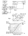
- a velocity sensor 40 which may be a coil surrounding a permanent magnet mounted on a stud fixed to the print head, produces a signal v, whose voltage is continuously proportional to the print head array velocity, to generate the necessary information using. the relationship between velocity and position for sinusoidal motion. If this relationship can be properly maintained, the need for an accurate and expensive position detection system can be eliminated.
- This velocity analog signal continuously indicates the velocity (and, by calculation, the position) of the print head 10 and is fed back via line 41 to a servo system 42 for continuously adjusting or tickling the energy input to the coil 22.
- the feedback signal v may be applied to a comparator CF together with the reference signal from the AC source 24 to produce the motor drive signal 44 required to replace losses and maintain the sinusoidal motion of the print head array at the resonant natural frequency of the system.
- the level of undesired vibration of this system is very low since the shuttle print head array reacts directly against a counterweight through the connecting frame 32 rather than being tied to a side frame through a motor and link.
- This sync signal is sent to a microprocessor 46 which produces an ENABLE command at the proper time to enable the printing process, i.e. when the printing elements 12 are positioned over their proper print positions.
- FIGURE 3 there is shown schematically the manner in which the velocity information available from the sensor 40 is converted in a sync generator 50, into sync pulses which occur at the zero crossings of the velocity characteristic of the shuttling print head array.
- Zero crossing detectors are well known in the art.
- the sync pulses available from sync generator 50 are applied to a sinusoidal time pattern signal generator 51 which contains microprocessor 46.
- This generator 51 produces enabling signals which allow print information from print information source 53 to be loaded into gating logic 52. After the last piece of information is transferred, the gating logic automatically allows energization of the correct print actuators.
- the information from source 53 constitutes the signal information representing the individual dots forming a dot matrix character to'be printed, as well known in the art.
- each printing element 12 comprises a print coil or actuator 56 and an associated printing stylus or wire 57.
- the associated print wire 57 is driven by the magnetic force established by printing coils 56 to impact a record medium, such as paper 59 through an inked ribbon 58.
- the individual printing elements 12 are energized in a sinusoidal time pattern to cause selected styli 57 to be displaced toward the record medium 59 to effect printing of dot indicia at selected equally spaced column locations on said print medium.
- the sync generator 50 detects the zero crossing points of the sensor output velocity signal to provide the desired sync pulses at the maximum left and right hand excursions of the print head.
- FIGURE 5 illustrates graphically in expanded form the relationship between equal dot column positions on the print medium 59 and the time of actuation of the printing styli 57.
- Generator 51 comprises microprocessor 46, such as an Intel 8088, which responds to the sync pulses to address a lookup table to determine when an enable signal must be generated over lead 55 for application to the gating logic 52 such that printing will take place by displacements of the printing styli 57 under the control of printing coils 56.
- microprocessor 46 such as an Intel 8088
- the displacements occur in a sinusoidal time pattern as shown by the abscissa of FIGURE 5 to cause selected printing styli, depending on the print information available from source 53, to be fired or displaced toward the record medium 59 to effect printing of indicia at selected equally spaced column locations on the print medium which is shown as the ordinate in FIGURE 5.
- the use of a microprocessor and a lookup table to obtain desired timing information is well known.
- the availability of print information from a source is also well known in the printing art as is the use of gates responsive to timing pulses and print information to obtain desired printing.
Landscapes
- Physics & Mathematics (AREA)
- Electromagnetism (AREA)
- Character Spaces And Line Spaces In Printers (AREA)
- Impact Printers (AREA)
Applications Claiming Priority (2)
| Application Number | Priority Date | Filing Date | Title |
|---|---|---|---|
| US43892882A | 1982-11-03 | 1982-11-03 | |
| US438928 | 1982-11-03 |
Publications (2)
| Publication Number | Publication Date |
|---|---|
| EP0109329A2 true EP0109329A2 (fr) | 1984-05-23 |
| EP0109329A3 EP0109329A3 (fr) | 1986-06-11 |
Family
ID=23742614
Family Applications (1)
| Application Number | Title | Priority Date | Filing Date |
|---|---|---|---|
| EP83402116A Withdrawn EP0109329A3 (fr) | 1982-11-03 | 1983-10-28 | Mécanisme d'entraínement équilibré pour tête d'impression |
Country Status (2)
| Country | Link |
|---|---|
| EP (1) | EP0109329A3 (fr) |
| WO (1) | WO1984001744A1 (fr) |
Cited By (4)
| Publication number | Priority date | Publication date | Assignee | Title |
|---|---|---|---|---|
| DE3433499A1 (de) * | 1983-09-13 | 1985-03-28 | Genicom Corp., Waynesboro, Va. | Verfahren zur elektrischen ansteuerung eines pendeldruckmechanismus |
| EP0169924A1 (fr) * | 1984-08-01 | 1986-02-05 | Mannesmann Tally Ges. mbH | Procédé et dispositif opto-électronique pour commander le point de déclenchement d'éléments d'impression utilisés en impression matricielle |
| EP0580330A2 (fr) * | 1992-07-24 | 1994-01-26 | Fujitsu Limited | Dispositif à navette pour imprimante |
| EP0581463A2 (fr) * | 1992-07-27 | 1994-02-02 | Fujitsu Limited | Tête à aiguilles pour l'impression par points |
Families Citing this family (3)
| Publication number | Priority date | Publication date | Assignee | Title |
|---|---|---|---|---|
| CA1328576C (fr) * | 1988-01-19 | 1994-04-19 | Gordon Brent Barrus | Imprimante a contrepoids de navette, graisseur de came et moteur a volant d'inertie integre offrant des caracteristiques ameliorees |
| CN113001972B (zh) * | 2021-03-15 | 2024-05-03 | 合肥海闻自动化设备有限公司 | 一种高速3d打印系统 |
| CN117309130A (zh) * | 2023-08-25 | 2023-12-29 | 深圳拓竹科技有限公司 | 一种滑块固有频率的测量方法、3d打印系统及电子设备 |
Citations (4)
| Publication number | Priority date | Publication date | Assignee | Title |
|---|---|---|---|---|
| US4116567A (en) * | 1976-12-22 | 1978-09-26 | Okidata Corporation | Printer synchronization control for shuttle having non-uniform velocity |
| US4180766A (en) * | 1977-02-04 | 1979-12-25 | Printronix, Inc. | Reciprocating linear drive mechanism |
| US4278019A (en) * | 1979-07-16 | 1981-07-14 | International Business Machines Corporation | All-points addressable dot printer |
| WO1982003123A1 (fr) * | 1981-03-09 | 1982-09-16 | Ncr Co | Imprimante a matrice de points |
Family Cites Families (3)
| Publication number | Priority date | Publication date | Assignee | Title |
|---|---|---|---|---|
| US4227455A (en) * | 1978-12-29 | 1980-10-14 | International Business Machines Corporation | Suspension arrangement for an oscillating body |
| JPS582075B2 (ja) * | 1979-08-14 | 1983-01-13 | 日本電信電話株式会社 | プリンタ |
| JPS57169367A (en) * | 1981-04-13 | 1982-10-19 | Hitachi Koki Co Ltd | Dot printer |
-
1983
- 1983-10-28 EP EP83402116A patent/EP0109329A3/fr not_active Withdrawn
- 1983-10-31 WO PCT/US1983/001684 patent/WO1984001744A1/fr unknown
Patent Citations (4)
| Publication number | Priority date | Publication date | Assignee | Title |
|---|---|---|---|---|
| US4116567A (en) * | 1976-12-22 | 1978-09-26 | Okidata Corporation | Printer synchronization control for shuttle having non-uniform velocity |
| US4180766A (en) * | 1977-02-04 | 1979-12-25 | Printronix, Inc. | Reciprocating linear drive mechanism |
| US4278019A (en) * | 1979-07-16 | 1981-07-14 | International Business Machines Corporation | All-points addressable dot printer |
| WO1982003123A1 (fr) * | 1981-03-09 | 1982-09-16 | Ncr Co | Imprimante a matrice de points |
Cited By (8)
| Publication number | Priority date | Publication date | Assignee | Title |
|---|---|---|---|---|
| DE3433499A1 (de) * | 1983-09-13 | 1985-03-28 | Genicom Corp., Waynesboro, Va. | Verfahren zur elektrischen ansteuerung eines pendeldruckmechanismus |
| FR2553035A1 (fr) * | 1983-09-13 | 1985-04-12 | Genicom Corp | Dispositif et procede pour entrainer un mecanisme d'imprimante a navette a sa frequence de resonance mecanique naturelle |
| DE3433499C2 (de) * | 1983-09-13 | 1998-01-29 | Genicom Corp | Pendeldrucker |
| EP0169924A1 (fr) * | 1984-08-01 | 1986-02-05 | Mannesmann Tally Ges. mbH | Procédé et dispositif opto-électronique pour commander le point de déclenchement d'éléments d'impression utilisés en impression matricielle |
| EP0580330A2 (fr) * | 1992-07-24 | 1994-01-26 | Fujitsu Limited | Dispositif à navette pour imprimante |
| EP0580330A3 (fr) * | 1992-07-24 | 1995-05-24 | Fujitsu Ltd | Dispositif à navette pour imprimante. |
| EP0581463A2 (fr) * | 1992-07-27 | 1994-02-02 | Fujitsu Limited | Tête à aiguilles pour l'impression par points |
| EP0581463A3 (fr) * | 1992-07-27 | 1995-06-14 | Fujitsu Ltd | Tête à aiguilles pour l'impression par points. |
Also Published As
| Publication number | Publication date |
|---|---|
| WO1984001744A1 (fr) | 1984-05-10 |
| EP0109329A3 (fr) | 1986-06-11 |
Similar Documents
| Publication | Publication Date | Title |
|---|---|---|
| US4180766A (en) | Reciprocating linear drive mechanism | |
| EP0357251A2 (fr) | Imprimante rapide à navette | |
| GB2063579A (en) | Hammer bank shuttle drive | |
| EP0109329A2 (fr) | Mécanisme d'entraînement équilibré pour tête d'impression | |
| US4049108A (en) | Actuator for a matrix print head | |
| JPS58110265A (ja) | ドツトプリンタ | |
| JPS6018297B2 (ja) | 走査用キャリア装置 | |
| US4128161A (en) | Vibratory device | |
| US3924528A (en) | Printer | |
| US4446789A (en) | Dot matrix printer | |
| US4134691A (en) | Printing head | |
| US4941405A (en) | Driving mechanism for reciprocating print shuttle | |
| US4869608A (en) | Resonant frequency reciprocating drive mechanism | |
| JPH0645246B2 (ja) | パルス始動式プリンタ用ハンマバンク駆動装置及び方法 | |
| JPS58500243A (ja) | ドツト・マトリツクス・プリンタ | |
| JPH045055A (ja) | シリアルプリンタ | |
| US5544964A (en) | Dot line printer having a balance shuttle | |
| EP0365267A2 (fr) | Tête d'impression pour imprimante par points à impact | |
| JPS63122562A (ja) | シヤトル型ドツトラインプリンタ | |
| EP0082329B1 (fr) | Mécanisme d'impression à navette compacte | |
| JPH0641211B2 (ja) | シヤトル型ラインプリンタ装置 | |
| JPS61206671A (ja) | 熱転写プリンタ | |
| JPH0655515B2 (ja) | シヤトル型ラインプリンタ装置 | |
| JPH0467957A (ja) | プリンタのインパクトドット印字ヘッド | |
| JPS6212617Y2 (fr) |
Legal Events
| Date | Code | Title | Description |
|---|---|---|---|
| PUAI | Public reference made under article 153(3) epc to a published international application that has entered the european phase |
Free format text: ORIGINAL CODE: 0009012 |
|
| AK | Designated contracting states |
Designated state(s): BE DE FR GB IT SE |
|
| RAP1 | Party data changed (applicant data changed or rights of an application transferred) |
Owner name: GENICOM CORPORATION |
|
| PUAL | Search report despatched |
Free format text: ORIGINAL CODE: 0009013 |
|
| AK | Designated contracting states |
Kind code of ref document: A3 Designated state(s): BE DE FR GB IT SE |
|
| STAA | Information on the status of an ep patent application or granted ep patent |
Free format text: STATUS: THE APPLICATION IS DEEMED TO BE WITHDRAWN |
|
| 18D | Application deemed to be withdrawn |
Effective date: 19861212 |
|
| RIN1 | Information on inventor provided before grant (corrected) |
Inventor name: POPELISH, JOHN ANTHONY Inventor name: MILLER, DONALD EUGENE Inventor name: CAULIER, PAUL ERNER Inventor name: READ, JOHN MICHAEL |