US4854271A - Intake manifold assembly for engines - Google Patents
Intake manifold assembly for engines Download PDFInfo
- Publication number
- US4854271A US4854271A US07/287,679 US28767988A US4854271A US 4854271 A US4854271 A US 4854271A US 28767988 A US28767988 A US 28767988A US 4854271 A US4854271 A US 4854271A
- Authority
- US
- United States
- Prior art keywords
- intake
- passages
- passage
- shorter
- longer
- Prior art date
- Legal status (The legal status is an assumption and is not a legal conclusion. Google has not performed a legal analysis and makes no representation as to the accuracy of the status listed.)
- Expired - Lifetime
Links
Images


Classifications
-
- F—MECHANICAL ENGINEERING; LIGHTING; HEATING; WEAPONS; BLASTING
- F02—COMBUSTION ENGINES; HOT-GAS OR COMBUSTION-PRODUCT ENGINE PLANTS
- F02M—SUPPLYING COMBUSTION ENGINES IN GENERAL WITH COMBUSTIBLE MIXTURES OR CONSTITUENTS THEREOF
- F02M35/00—Combustion-air cleaners, air intakes, intake silencers, or induction systems specially adapted for, or arranged on, internal-combustion engines
- F02M35/10—Air intakes; Induction systems
- F02M35/104—Intake manifolds
- F02M35/116—Intake manifolds for engines with cylinders in V-arrangement or arranged oppositely relative to the main shaft
-
- F—MECHANICAL ENGINEERING; LIGHTING; HEATING; WEAPONS; BLASTING
- F02—COMBUSTION ENGINES; HOT-GAS OR COMBUSTION-PRODUCT ENGINE PLANTS
- F02B—INTERNAL-COMBUSTION PISTON ENGINES; COMBUSTION ENGINES IN GENERAL
- F02B27/00—Use of kinetic or wave energy of charge in induction systems, or of combustion residues in exhaust systems, for improving quantity of charge or for increasing removal of combustion residues
- F02B27/02—Use of kinetic or wave energy of charge in induction systems, or of combustion residues in exhaust systems, for improving quantity of charge or for increasing removal of combustion residues the systems having variable, i.e. adjustable, cross-sectional areas, chambers of variable volume, or like variable means
- F02B27/0205—Use of kinetic or wave energy of charge in induction systems, or of combustion residues in exhaust systems, for improving quantity of charge or for increasing removal of combustion residues the systems having variable, i.e. adjustable, cross-sectional areas, chambers of variable volume, or like variable means characterised by the charging effect
- F02B27/0215—Oscillating pipe charging, i.e. variable intake pipe length charging
-
- F—MECHANICAL ENGINEERING; LIGHTING; HEATING; WEAPONS; BLASTING
- F02—COMBUSTION ENGINES; HOT-GAS OR COMBUSTION-PRODUCT ENGINE PLANTS
- F02B—INTERNAL-COMBUSTION PISTON ENGINES; COMBUSTION ENGINES IN GENERAL
- F02B27/00—Use of kinetic or wave energy of charge in induction systems, or of combustion residues in exhaust systems, for improving quantity of charge or for increasing removal of combustion residues
- F02B27/02—Use of kinetic or wave energy of charge in induction systems, or of combustion residues in exhaust systems, for improving quantity of charge or for increasing removal of combustion residues the systems having variable, i.e. adjustable, cross-sectional areas, chambers of variable volume, or like variable means
- F02B27/0226—Use of kinetic or wave energy of charge in induction systems, or of combustion residues in exhaust systems, for improving quantity of charge or for increasing removal of combustion residues the systems having variable, i.e. adjustable, cross-sectional areas, chambers of variable volume, or like variable means characterised by the means generating the charging effect
- F02B27/0247—Plenum chambers; Resonance chambers or resonance pipes
- F02B27/0263—Plenum chambers; Resonance chambers or resonance pipes the plenum chamber and at least one of the intake ducts having a common wall, and the intake ducts wrap partially around the plenum chamber, i.e. snail-type
-
- F—MECHANICAL ENGINEERING; LIGHTING; HEATING; WEAPONS; BLASTING
- F02—COMBUSTION ENGINES; HOT-GAS OR COMBUSTION-PRODUCT ENGINE PLANTS
- F02B—INTERNAL-COMBUSTION PISTON ENGINES; COMBUSTION ENGINES IN GENERAL
- F02B75/00—Other engines
- F02B75/16—Engines characterised by number of cylinders, e.g. single-cylinder engines
- F02B75/18—Multi-cylinder engines
- F02B75/22—Multi-cylinder engines with cylinders in V, fan, or star arrangement
-
- F—MECHANICAL ENGINEERING; LIGHTING; HEATING; WEAPONS; BLASTING
- F02—COMBUSTION ENGINES; HOT-GAS OR COMBUSTION-PRODUCT ENGINE PLANTS
- F02M—SUPPLYING COMBUSTION ENGINES IN GENERAL WITH COMBUSTIBLE MIXTURES OR CONSTITUENTS THEREOF
- F02M35/00—Combustion-air cleaners, air intakes, intake silencers, or induction systems specially adapted for, or arranged on, internal-combustion engines
- F02M35/10—Air intakes; Induction systems
- F02M35/10006—Air intakes; Induction systems characterised by the position of elements of the air intake system in direction of the air intake flow, i.e. between ambient air inlet and supply to the combustion chamber
- F02M35/10026—Plenum chambers
- F02M35/10039—Intake ducts situated partly within or on the plenum chamber housing
-
- F—MECHANICAL ENGINEERING; LIGHTING; HEATING; WEAPONS; BLASTING
- F02—COMBUSTION ENGINES; HOT-GAS OR COMBUSTION-PRODUCT ENGINE PLANTS
- F02M—SUPPLYING COMBUSTION ENGINES IN GENERAL WITH COMBUSTIBLE MIXTURES OR CONSTITUENTS THEREOF
- F02M35/00—Combustion-air cleaners, air intakes, intake silencers, or induction systems specially adapted for, or arranged on, internal-combustion engines
- F02M35/10—Air intakes; Induction systems
- F02M35/10006—Air intakes; Induction systems characterised by the position of elements of the air intake system in direction of the air intake flow, i.e. between ambient air inlet and supply to the combustion chamber
- F02M35/10026—Plenum chambers
- F02M35/10065—Valves arranged in the plenum chamber
-
- F—MECHANICAL ENGINEERING; LIGHTING; HEATING; WEAPONS; BLASTING
- F02—COMBUSTION ENGINES; HOT-GAS OR COMBUSTION-PRODUCT ENGINE PLANTS
- F02M—SUPPLYING COMBUSTION ENGINES IN GENERAL WITH COMBUSTIBLE MIXTURES OR CONSTITUENTS THEREOF
- F02M35/00—Combustion-air cleaners, air intakes, intake silencers, or induction systems specially adapted for, or arranged on, internal-combustion engines
- F02M35/10—Air intakes; Induction systems
- F02M35/10091—Air intakes; Induction systems characterised by details of intake ducts: shapes; connections; arrangements
- F02M35/10111—Substantially V-, C- or U-shaped ducts in direction of the flow path
-
- F—MECHANICAL ENGINEERING; LIGHTING; HEATING; WEAPONS; BLASTING
- F02—COMBUSTION ENGINES; HOT-GAS OR COMBUSTION-PRODUCT ENGINE PLANTS
- F02M—SUPPLYING COMBUSTION ENGINES IN GENERAL WITH COMBUSTIBLE MIXTURES OR CONSTITUENTS THEREOF
- F02M35/00—Combustion-air cleaners, air intakes, intake silencers, or induction systems specially adapted for, or arranged on, internal-combustion engines
- F02M35/10—Air intakes; Induction systems
- F02M35/10242—Devices or means connected to or integrated into air intakes; Air intakes combined with other engine or vehicle parts
- F02M35/10268—Heating, cooling or thermal insulating means
-
- F—MECHANICAL ENGINEERING; LIGHTING; HEATING; WEAPONS; BLASTING
- F02—COMBUSTION ENGINES; HOT-GAS OR COMBUSTION-PRODUCT ENGINE PLANTS
- F02M—SUPPLYING COMBUSTION ENGINES IN GENERAL WITH COMBUSTIBLE MIXTURES OR CONSTITUENTS THEREOF
- F02M35/00—Combustion-air cleaners, air intakes, intake silencers, or induction systems specially adapted for, or arranged on, internal-combustion engines
- F02M35/10—Air intakes; Induction systems
- F02M35/104—Intake manifolds
- F02M35/108—Intake manifolds with primary and secondary intake passages
- F02M35/1085—Intake manifolds with primary and secondary intake passages the combustion chamber having multiple intake valves
-
- F—MECHANICAL ENGINEERING; LIGHTING; HEATING; WEAPONS; BLASTING
- F02—COMBUSTION ENGINES; HOT-GAS OR COMBUSTION-PRODUCT ENGINE PLANTS
- F02B—INTERNAL-COMBUSTION PISTON ENGINES; COMBUSTION ENGINES IN GENERAL
- F02B75/00—Other engines
- F02B75/16—Engines characterised by number of cylinders, e.g. single-cylinder engines
- F02B75/18—Multi-cylinder engines
- F02B2075/1804—Number of cylinders
- F02B2075/1824—Number of cylinders six
-
- F—MECHANICAL ENGINEERING; LIGHTING; HEATING; WEAPONS; BLASTING
- F02—COMBUSTION ENGINES; HOT-GAS OR COMBUSTION-PRODUCT ENGINE PLANTS
- F02B—INTERNAL-COMBUSTION PISTON ENGINES; COMBUSTION ENGINES IN GENERAL
- F02B27/00—Use of kinetic or wave energy of charge in induction systems, or of combustion residues in exhaust systems, for improving quantity of charge or for increasing removal of combustion residues
- F02B27/02—Use of kinetic or wave energy of charge in induction systems, or of combustion residues in exhaust systems, for improving quantity of charge or for increasing removal of combustion residues the systems having variable, i.e. adjustable, cross-sectional areas, chambers of variable volume, or like variable means
- F02B27/0226—Use of kinetic or wave energy of charge in induction systems, or of combustion residues in exhaust systems, for improving quantity of charge or for increasing removal of combustion residues the systems having variable, i.e. adjustable, cross-sectional areas, chambers of variable volume, or like variable means characterised by the means generating the charging effect
- F02B27/0268—Valves
- F02B27/0273—Flap valves
-
- F—MECHANICAL ENGINEERING; LIGHTING; HEATING; WEAPONS; BLASTING
- F02—COMBUSTION ENGINES; HOT-GAS OR COMBUSTION-PRODUCT ENGINE PLANTS
- F02F—CYLINDERS, PISTONS OR CASINGS, FOR COMBUSTION ENGINES; ARRANGEMENTS OF SEALINGS IN COMBUSTION ENGINES
- F02F2200/00—Manufacturing
- F02F2200/06—Casting
-
- Y—GENERAL TAGGING OF NEW TECHNOLOGICAL DEVELOPMENTS; GENERAL TAGGING OF CROSS-SECTIONAL TECHNOLOGIES SPANNING OVER SEVERAL SECTIONS OF THE IPC; TECHNICAL SUBJECTS COVERED BY FORMER USPC CROSS-REFERENCE ART COLLECTIONS [XRACs] AND DIGESTS
- Y02—TECHNOLOGIES OR APPLICATIONS FOR MITIGATION OR ADAPTATION AGAINST CLIMATE CHANGE
- Y02T—CLIMATE CHANGE MITIGATION TECHNOLOGIES RELATED TO TRANSPORTATION
- Y02T10/00—Road transport of goods or passengers
- Y02T10/10—Internal combustion engine [ICE] based vehicles
- Y02T10/12—Improving ICE efficiencies
Definitions
- the present invention relates to an intake manifold assembly for use with an engine, and more particularly to an intake manifold assembly having a variable intake passage length for use with an automotive engine.
- Intake manifolds for engines are generally disposed between the intake ports of a cylinder head and a carburetor or throttle body having a throttle valve for controlling the amount of intake air.
- the intake manifold has as many branch passages as the number of intake ports to distribute the air into the intake ports.
- an intake manifold system of a variable intake passage length as disclosed in U.S. patent application Ser. No. 647,713, filed Sept. 5, 1984 corresponding to Japanese Patent Application No. 58(1983)-248657, now U.S. Pat. No. 4,669,428.
- the effective intake passage length is reduced when the engine rotates at a high speed or operates under a high load.
- the charging efficiency of the engine is increased over a full engine operation range for improved engine output performance.
- the previously proposed intake manifold system includes longer intake passages and shorter intake passages extending parallel thereto and having auxiliary throttle valves or bypass valves which will be opened when the engine rotates at a high speed or operates under a high load and closed at low engine speed or load, to thereby selectively connect the longer and shorter intake passages to the intake ports of the engine.
- the air is introduced through the longer intake passages into the intake ports.
- the bypass valves are open to allow the air to pass through the shorter intake passages into the intake ports. Therefore, when the engine operates at a lower speed or load, the air mixture is fed efficiently and effectively under its inertia developed during travel through the longer intake passages.
- the air supplied through the shorter intake passages is subjected to a smaller degree of resistance.
- the charging efficiency of the engine is increased at higher and lower engine speeds or loads, resulting in improved engine power output.
- the intake manifold system of the above structure has a relatively complex passage arrangement, and is large in size especially where an intake chamber of a relatively large volume is employed as a surge tank. If the intake manifold system is to be associated with an automotive engine, it has been found difficult to provide sufficient space for installing the intake manifold system in the engine compartment in the automobile.
- an intake manifold assembly for use with an engine including intake ports, comprising a branch passage body for introducing air from an upstream end to a downstream end thereof, the branch passage body being adapted to be connected at the downstream end to the intake ports and at the upstream end to a main throttle valve for controlling air drawn into the branch passage body.
- the branch passage body has an intake chamber at the upstream end, adapted to communicate with the main throttle valve, a plurality of shorter passages extending upwardly from the intake chamber and each having an auxiliary throttle valve for selectively opening and closing the shorter passage, a plurality of longer passages extending from the intake chamber around a lower side of the intake chamber, the shorter and longer passages having downstream ends joined to each other at respective junctions, and a plurality of intake passages extending downstream from the junctions, respectively, and adapted to be connected to the intake ports.
- the branch passage body comprises a first member defining at least a portion of the longer passages and the intake chamber, and a second member having at least the intake passage, the first and second members being vertically stacked one on the other.
- the intake manifold assembly of a variable passage length can have passages of different lengths without increasing the dimensions of the intake manifold assembly along the crankshaft.
- FIG. 1 is a front elevational view, partly in vertical cross section, of an engine incorporating an intake manifold assembly according to the present invention
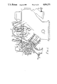
- FIG. 2 is a plan view of the intake manifold assembly shown in FIG. 1;
- FIG. 3 is a cross-sectional view of the intake manifold assembly taken along line III--III of FIG. 2;
- FIG. 4 is a fragmentary exploded perspective view, partly cut away, of the intake manifold assembly illustrated in FIG. 1.
- FIG. 1 shows a V6 internal combustion engine which incorporates therein an intake manifold assembly of the present invention.
- the engine preferrably includes four valves for each engine cylinder although only two valves are visable in FIG. 1.
- the engine includes two cylinder arrays or banks 1, 2 of identical construction which are angularly spaced at a bank angle of 90 degrees in a V shape.
- Each of the cylinder banks 1, 2 comprises a cylinder block 5 having three cylinders 4 (only one shown) defined therein at spaced intervals along the axis of a crankshaft 3.
- the engine also includes a pair of cylinder heads 6 fixed to the upper ends of the cylinder blocks 5, respectively.
- Each of the cylinder heads 6 has openings defined in upper and lateral sides that are closed by a cam cover 7 and a rocker arm cover 8, respectively.
- a camshaft 9 is rotatably disposed in the cylinder head 6 and covered with the cam cover 7, the camshaft 9 being operatively coupled to the crankshaft 3 through timing pulleys and a timing belt (not shown).
- the camshaft 9 has a plurality of pairs of cams 9a, 9b spaced at intervals therealong, the cams 9a, 9b in each pair being held in sliding engagement with first and second rocker arms 10, 11, respectively.
- the first rocker arm 10 has one end pivotally supported on a hemispherical head of a hydraulic tappet or lash adjuster 12. The opposite end of the first rocker arm 10 engages an end of an intake valve 13 which is normally spring-biased in a direction to close an intake port associated with the intake valve 13.
- the second rocker arm 11 has one end pivotally supported on a hemispherical head of a hydraulic tappet or lash adjuster 12'.
- the opposite end of the second rocker arm 11 is operatively coupled by a pusher rod 14 to one end of a third rocker arm 15 so that angular movement of the second rocker arm 11 can be transmitted to the third rocker arm 15 through the pusher rod 14.
- the third rocker arm 15 is angularly movably supported by a rocker shaft 16. The opposite end of the third rocker arm 15 is held in engagement with an end of an exhaust valve 17 that is normally spring-biased in a direction to close an exhaust port associated with the exhaust valve 17.
- each engine cylinder 4 has two pairs of the intake and exhaust valves 13, 17, but only one pair is shown in FIG. 1.
- a spark plug 19 is threadedly mounted centrally in each cylinder 4 of the cylinder head 6.
- the spark plug 19 has a side electrode 19a projecting into the combustion chamber 18, which is defined between the upper end surface of a piston 20 slidably disposed in the cylinder 4 and the lower surface of the cylinder head 6.
- An exhaust manifold 22 is attached to the outer ends of exhaust ports 21 communicating with the combustion chambers 18 through the exhaust valves 17.
- the exhaust manifold 22 is connected to a muffler (not shown) to discharge the exhaust gas through the muffler into the atmosphere.
- An O 2 sensor 23 is threadedly mounted on the exhaust manifold 22 for detecting the density of oxygen contained in the exhaust gas as it flows through the exhaust manifold 22.
- a signal indicative of the oxygen density is fed from the O 2 sensor 23 back to a controller (not shown) which controls the amount of fuel injected according to the amount of intake air in order to achieve a stoichiometric air-fuel ratio.
- the piston 20 is operatively coupled to the crankshaft 3 by a connecting rod 24 which converts reciprocating movement of the piston 20 produced under the pressure of fuel combustion into rotation of the crankshaft.
- the engine is relatively conventional and does not comprise a part of the present invention.
- the cylinder head 6 has an upper surface lying flush with the upper surface of a flange 50 in which there are defined intake ports 25 communicating through the intake valves 13 with the combustion chambers 18.
- a branch passage body 27 having an intake pipe 26 communicating with each of the intake ports 25 is mounted on the upper surface of the flange 50 by means of bolts 51 (FIG. 2) that are threaded downwardly into the flange 50.
- the branch passage body 27 has flanges 52 located near the joints between the intake pipes 26 and the intake ports 25.
- Fuel injection nozzles 28 are mounted on the flanges 52 and have fuel outlet ports directed downwardly toward the respective intake ports 25.
- the branch passage body 27 comprises an upper member 27a, a lower member 27b, and an intermediate member 27c sandwiched between the upper and lower members 27a, 27b and fastened by bolts into a unitary assembly.
- the upper, intermediate, and lower members 27a, 27b, 27c are in the form of hollow members which are separately cast.
- the upper member 27a is divided into separate sections by pipe walls 40 of the intake pipes 26 which have upper arcuately curved portions.
- the divided sections of the upper member 27a have intake passages 29 defined in downstream portions thereof and extending downwardly.
- the intake passages 29 are alternately connected to the intake ports 25 of the cylinders 4 in the cylinder banks 1, 2.
- the divided sections of the upper member 27a also include downstream ends of longer and shorter passages 42, 43 defined by partitions 41 extending transversely to the pipe walls 40.
- the intermediate member 27c includes partitions 44 which define middle portions of the longer and shorter passages 42, 43.
- the middle portions of the shorter passages 43 can be opened and closed by auxiliary throttle valves 45 angularly movably supported in the intermediate member 27c.
- the lower member 27b has an intake chamber 33 defined centrally therein and shared by all of the cylinders 4.
- the intake chamber 33 is in the form of an elongate chamber extending along the direction of the crankshaft 3 and has a volume large enough to eliminate intake air pulsations.
- the intake chamber 33 is connected to a throttle body 34 by an upstream intake passage 32 inclined upwardly toward an upstream end thereof which is joined to the throttle body 34.
- a water passage 30 extending along the crankshaft 3 is defined on the lower surface of the bottom wall of the lower member 27b for the passage of an engine coolant therethrough to heat the air that is drawn into the intake chamber 33.
- the lower member 27b has openings 35a defined in an upper wall thereof in communication with the intake chamber 33 and associated with the respective cylinders 4, and openings 35b defined in a side wall thereof in communication with the intake chamber 33 and associated with the respective cylinders 4.
- the upper openings 35a communicate respectively with the upstream ends of the shorter passages 43, whereas the side openings 35b communicate respectively with the upstream ends of the longer passages 42 which extend around the lower side of the intake chamber 33.
- the shorter passages 43 having the respective auxiliary throttle valves 45 therein extend as straight vertical passages, through which the upper openings 35a of the intake chamber 33 communicate with the intake passages 29, respectively.
- the longer passages 42 extend from the side openings 35b of the intake chamber 33 around the lower side of the intake chamber 33 and then upwardly parallel to the shorter passages 43 defined by the partitions 41, and are joined to downstream ends of the shorter passages 43 and the intake passages 29.
- the auxiliary throttle valves 45 can be driven by a dual diaphragm actuator 46 through a link mechanism 47 (FIGS. 1 and 2).
- the diaphragm actuator 46 is operated by the vacuum of intake air, and can provide two different strokes using a solenoid-operated valve (not shown) which is operated according to the opening of a main throttle valve (not shown) in the throttle body 34. Therefore, the auxiliary throttle valves 45 can be opened to two different degrees dependent on the condition in which the engine is operated.
- the auxiliary throttle valves 45 are fully closed by the actuator 46.
- the intake air which has been limited by the main throttle valve in the throttle body 34 is introduced from the intake passage 32 into the intake chamber 33 and then flows in the direction of the arrow A through the opening 35b, the longer passages 42, and the intake pipes 26 into the intake ports 25, from which the air is drawn into the combustion chambers 18.
- the auxiliary throttle valves 45 are partly opened to allow a portion of the intake air to flow in the direction of the arrows B through the openings 35a, the shorter passages 43, and the intake passages 29 into the intake ports 25, whereas the remaining air flows in the direction of the arrow A through the opening 35b, the longer passages 42, and the intake pipes 26 into the intake ports 25.
- the auxiliary throttle valves 45 When the engine operates at a higher speed or load, the auxiliary throttle valves 45 are fully opened to permit most of the intake air to flow in the direction of the arrow B through the openings 35a, the shorter passages 43, and the intake passages 29 into the intake ports 25 and then the combustion chambers 28.
- the auxiliary throttle valve 45 controlled according to the condition in which the engine is operated serves to increase and reduce the inertial energy of and resistance to air drawn into the combustion chamber 48 for smoothing torques in a wider range.
- the intake passage 32 between the main throttle valve in the throttle body 34 and the intake chamber 33 that serve as a surge tank can be of a desired length without excessively increasing the dimension of the assembly along the crankshaft 3 and without physical interference with accessories of the engine.
- the desired passage lengths for the longer and shorter passages 42, 43 can be obtained by stacking the upper, intermediate, and lower members 27a, 27c, 27b as a unitary assembly, and positioning the joint between the upper and intermediate members 27a, 27c to lie flush with the lower surfaces of the flanges 52 through which the downstream intake passages 29 pass.
- the branch passage body 27 of the above construction can easily be manufactured.
- the longer passages 42 can be placed in a small space as it extends around the intake chamber 33 which serves to eliminate intake air pulsations.
- the relatively complex intake pipes of the intake manifold assembly can therefore be manufactured easily, and the desired passage lengths therefor can be accomplished in a compact arrangement.
- the engine associated with the intake manifold assembly of the present invention can be made small in size and designed for high performance.
- the intake manifold assembly is disposed in a space defined between the cylinder banks of the engine.
Applications Claiming Priority (2)
| Application Number | Priority Date | Filing Date | Title |
|---|---|---|---|
| JP60199073A JPS6285118A (ja) | 1985-09-09 | 1985-09-09 | エンジン用吸気マニホ−ルド装置 |
| JP60-199073 | 1985-09-09 |
Related Parent Applications (1)
| Application Number | Title | Priority Date | Filing Date |
|---|---|---|---|
| US06904924 Continuation | 1986-09-08 |
Publications (1)
| Publication Number | Publication Date |
|---|---|
| US4854271A true US4854271A (en) | 1989-08-08 |
Family
ID=16401653
Family Applications (1)
| Application Number | Title | Priority Date | Filing Date |
|---|---|---|---|
| US07/287,679 Expired - Lifetime US4854271A (en) | 1985-09-09 | 1988-12-20 | Intake manifold assembly for engines |
Country Status (5)
| Country | Link |
|---|---|
| US (1) | US4854271A (ja) |
| EP (1) | EP0215628B1 (ja) |
| JP (1) | JPS6285118A (ja) |
| CA (1) | CA1278963C (ja) |
| DE (1) | DE3679751D1 (ja) |
Cited By (17)
| Publication number | Priority date | Publication date | Assignee | Title |
|---|---|---|---|---|
| US5005532A (en) * | 1989-02-22 | 1991-04-09 | Siemens-Bendix Automotive Electronics Limited | Integrated tuned induction system |
| US5027753A (en) * | 1989-03-09 | 1991-07-02 | Honda Giken Kogyo Kabushiki Kaisha | Intake system of multi-cylinder internal combustion engine |
| US5056473A (en) * | 1989-05-29 | 1991-10-15 | Honda Giken Kogyo Kabushiki Kaisha | Intake device for multi-cylinder internal combustion engine |
| US5105774A (en) * | 1990-06-08 | 1992-04-21 | Fiat Auto Spa | Intake system for multicylinder internal combustion engines for motor vehicles |
| US5127371A (en) * | 1989-10-11 | 1992-07-07 | Showa Aluminum Corporation | Intake manifold |
| US5492088A (en) * | 1992-08-26 | 1996-02-20 | Audi Ag | Intake pipe system for a multicylinder internal combustion engine |
| US5787851A (en) * | 1993-12-29 | 1998-08-04 | Yamaha Hatsudoki Kabushiki Kaisha | Intake control system |
| US5901677A (en) * | 1993-12-24 | 1999-05-11 | Audi Ag | Inlet pipe system for a multicylinder internal combustion engine |
| FR2807108A1 (fr) * | 2000-04-04 | 2001-10-05 | Magneti Marelli France | Collecteur d'admission d'air a elargissement brusque, pour moteur a combustion interne |
| US6408809B2 (en) * | 2000-04-17 | 2002-06-25 | Yamaha Hatsudoki Kabushiki Kaisha | Intake control device for multi-cylinder V-type engine |
| US6718930B2 (en) * | 2001-07-23 | 2004-04-13 | Suzuki Motor Corporation | Intake system of a V-type engine |
| US6732695B2 (en) * | 1999-08-03 | 2004-05-11 | Filterwerk Mann & Hummel Gmbh | Intake manifold for an internal combustion engine |
| EP1524419A1 (de) * | 2003-10-14 | 2005-04-20 | Pierburg GmbH | Luftansaugkanalsystem |
| US20100108010A1 (en) * | 2008-09-16 | 2010-05-06 | Kawasaki Jukogyo Kabushiki Kaisha | Air-intake duct and air-intake structure |
| US20100162984A1 (en) * | 2007-05-30 | 2010-07-01 | Honda Motor Co., Ltd. | Intake manifold for internal combustion engine |
| US20160230718A1 (en) * | 2015-02-10 | 2016-08-11 | Dr. Ing. H.C. F. Porsche Aktiengesellschaft | Control device for uniformly distributing gases and/or liquids between at least two containers |
| CN111878270A (zh) * | 2019-05-03 | 2020-11-03 | 曼恩能源方案有限公司 | 内燃机的增压空气管线和内燃机 |
Families Citing this family (9)
| Publication number | Priority date | Publication date | Assignee | Title |
|---|---|---|---|---|
| US4922864A (en) * | 1988-07-19 | 1990-05-08 | Fuji Jukogyo Kabushiki Kaisha | System for controlling air intake for an automotive engine |
| GB2221954B (en) * | 1988-08-16 | 1992-07-08 | Austin Rover Group | An internal combustion engine inlet manifold |
| DE3921081A1 (de) * | 1989-06-28 | 1991-01-10 | Audi Ag | Saugrohranlage fuer eine mehrzylinder-brennkraftmaschine |
| JPH0681719A (ja) * | 1992-08-31 | 1994-03-22 | Hitachi Ltd | 内燃機関の吸気装置 |
| DE4423427C2 (de) * | 1994-07-05 | 2000-10-05 | Mann & Hummel Filter | Ansauganlage für eine Mehrzylinder-Brennkraftmaschine |
| JP3210825B2 (ja) * | 1995-01-14 | 2001-09-25 | ヤマハ発動機株式会社 | V型多気筒エンジンの吸気装置 |
| DE102006054182A1 (de) * | 2006-11-16 | 2008-05-21 | Robert Bosch Gmbh | Verfahren und Vorrichtung zum Betreiben einer Brennkraftmaschine mit mehreren Zylinderbänken |
| JP5912013B2 (ja) * | 2010-12-28 | 2016-04-27 | 株式会社ミクニ | 樹脂製インテークマニホールド |
| GR1009185B (el) * | 2016-08-04 | 2018-01-09 | Ανδρεας Λεωνιδα Σερλιδακης | Συστημα μειωσης αεριων ρυπων και καταναλωσης καυσιμων σε μηχανες εσωτερικης καυσης |
Citations (5)
| Publication number | Priority date | Publication date | Assignee | Title |
|---|---|---|---|---|
| US2835235A (en) * | 1955-06-20 | 1958-05-20 | Daimler Benz Ag | Intake manifold for internal combustion engines |
| JPS60258A (ja) * | 1983-06-17 | 1985-01-05 | Fujitsu General Ltd | 給湯装置 |
| US4617897A (en) * | 1984-01-23 | 1986-10-21 | Mazda Motor Corporation | Intake system for internal combustion engines |
| US4669428A (en) * | 1983-09-08 | 1987-06-02 | Honda Giken Kogyo Kabushiki Kaisha | Intake manifold for multi-cylinder internal combustion engines |
| US4726329A (en) * | 1985-05-04 | 1988-02-23 | Austin Rover Group Limited | Inlet manifold for V-configuration internal combustion engines |
Family Cites Families (8)
| Publication number | Priority date | Publication date | Assignee | Title |
|---|---|---|---|---|
| AT253305B (de) * | 1962-12-17 | 1967-04-10 | Hans Dipl Ing Dr Techn List | Ansaugeinrichtung bei Brennkraftmaschinen |
| FR1395660A (fr) * | 1964-02-27 | 1965-04-16 | Tecalemit | Procédé et dispositif pour modifier les conditions de remplissage en gaz de cylindres de moteurs, compresseurs ou machines analogues |
| FR1457282A (fr) * | 1964-12-14 | 1966-01-24 | Inst Francais Du Petrole | Perfectionnements à l'alimentation des moteurs à piston rotatif |
| JPS56115819A (en) * | 1980-02-19 | 1981-09-11 | Nissan Diesel Motor Co Ltd | Suction device for inertia supercharging type internal-combustion engine |
| US4440120A (en) * | 1982-05-24 | 1984-04-03 | General Motors Corporation | Compact ram tube engine air intake manifold |
| GB2121473A (en) * | 1982-06-01 | 1983-12-21 | Ford Motor Co | Intake manifold for an internal combustion engine |
| JPS59120717A (ja) * | 1982-12-28 | 1984-07-12 | Nissan Motor Co Ltd | 内燃機関の吸気路装置 |
| DE3437102A1 (de) * | 1984-10-10 | 1986-04-10 | Audi AG, 8070 Ingolstadt | Saugrohranlage fuer mehrzylinder-brennkraftmaschinen |
-
1985
- 1985-09-09 JP JP60199073A patent/JPS6285118A/ja active Pending
-
1986
- 1986-09-08 CA CA000517658A patent/CA1278963C/en not_active Expired - Fee Related
- 1986-09-09 EP EP86306937A patent/EP0215628B1/en not_active Expired - Lifetime
- 1986-09-09 DE DE8686306937T patent/DE3679751D1/de not_active Expired - Fee Related
-
1988
- 1988-12-20 US US07/287,679 patent/US4854271A/en not_active Expired - Lifetime
Patent Citations (5)
| Publication number | Priority date | Publication date | Assignee | Title |
|---|---|---|---|---|
| US2835235A (en) * | 1955-06-20 | 1958-05-20 | Daimler Benz Ag | Intake manifold for internal combustion engines |
| JPS60258A (ja) * | 1983-06-17 | 1985-01-05 | Fujitsu General Ltd | 給湯装置 |
| US4669428A (en) * | 1983-09-08 | 1987-06-02 | Honda Giken Kogyo Kabushiki Kaisha | Intake manifold for multi-cylinder internal combustion engines |
| US4617897A (en) * | 1984-01-23 | 1986-10-21 | Mazda Motor Corporation | Intake system for internal combustion engines |
| US4726329A (en) * | 1985-05-04 | 1988-02-23 | Austin Rover Group Limited | Inlet manifold for V-configuration internal combustion engines |
Cited By (24)
| Publication number | Priority date | Publication date | Assignee | Title |
|---|---|---|---|---|
| US5005532A (en) * | 1989-02-22 | 1991-04-09 | Siemens-Bendix Automotive Electronics Limited | Integrated tuned induction system |
| US5027753A (en) * | 1989-03-09 | 1991-07-02 | Honda Giken Kogyo Kabushiki Kaisha | Intake system of multi-cylinder internal combustion engine |
| US5056473A (en) * | 1989-05-29 | 1991-10-15 | Honda Giken Kogyo Kabushiki Kaisha | Intake device for multi-cylinder internal combustion engine |
| US5127371A (en) * | 1989-10-11 | 1992-07-07 | Showa Aluminum Corporation | Intake manifold |
| US5105774A (en) * | 1990-06-08 | 1992-04-21 | Fiat Auto Spa | Intake system for multicylinder internal combustion engines for motor vehicles |
| US5492088A (en) * | 1992-08-26 | 1996-02-20 | Audi Ag | Intake pipe system for a multicylinder internal combustion engine |
| US5901677A (en) * | 1993-12-24 | 1999-05-11 | Audi Ag | Inlet pipe system for a multicylinder internal combustion engine |
| US5787851A (en) * | 1993-12-29 | 1998-08-04 | Yamaha Hatsudoki Kabushiki Kaisha | Intake control system |
| US6732695B2 (en) * | 1999-08-03 | 2004-05-11 | Filterwerk Mann & Hummel Gmbh | Intake manifold for an internal combustion engine |
| FR2807108A1 (fr) * | 2000-04-04 | 2001-10-05 | Magneti Marelli France | Collecteur d'admission d'air a elargissement brusque, pour moteur a combustion interne |
| WO2001075295A1 (fr) * | 2000-04-04 | 2001-10-11 | Magneti Marelli France | Collecteur d'admission d'air a elargissement brusque, pour moteur a combustion interne |
| US6691662B2 (en) | 2000-04-04 | 2004-02-17 | Magneti Marelli France | Air intake manifold with sudden enlargement for internal combustion engine |
| US6408809B2 (en) * | 2000-04-17 | 2002-06-25 | Yamaha Hatsudoki Kabushiki Kaisha | Intake control device for multi-cylinder V-type engine |
| US6718930B2 (en) * | 2001-07-23 | 2004-04-13 | Suzuki Motor Corporation | Intake system of a V-type engine |
| EP1524419A1 (de) * | 2003-10-14 | 2005-04-20 | Pierburg GmbH | Luftansaugkanalsystem |
| US20100162984A1 (en) * | 2007-05-30 | 2010-07-01 | Honda Motor Co., Ltd. | Intake manifold for internal combustion engine |
| US8365695B2 (en) * | 2007-05-30 | 2013-02-05 | Honda Motor Co., Ltd. | Intake manifold for internal combustion engine |
| US20100108010A1 (en) * | 2008-09-16 | 2010-05-06 | Kawasaki Jukogyo Kabushiki Kaisha | Air-intake duct and air-intake structure |
| US8151754B2 (en) * | 2008-09-16 | 2012-04-10 | Kawasaki Jukogyo Kabushiki Kaisha | Air-intake duct and air-intake structure |
| US20160230718A1 (en) * | 2015-02-10 | 2016-08-11 | Dr. Ing. H.C. F. Porsche Aktiengesellschaft | Control device for uniformly distributing gases and/or liquids between at least two containers |
| US9803597B2 (en) * | 2015-02-10 | 2017-10-31 | Dr. Ing. H.C.F. Porsche Aktiengesellschaft | Control device for uniformly distributing gases and/or liquids between at least two containers |
| CN111878270A (zh) * | 2019-05-03 | 2020-11-03 | 曼恩能源方案有限公司 | 内燃机的增压空气管线和内燃机 |
| US11193461B2 (en) * | 2019-05-03 | 2021-12-07 | Man Energy Solutions Se | Charge air line of an internal combustion engine and internal combustion engine |
| CN111878270B (zh) * | 2019-05-03 | 2024-01-30 | 曼恩能源方案有限公司 | 内燃机的增压空气管线和内燃机 |
Also Published As
| Publication number | Publication date |
|---|---|
| EP0215628A2 (en) | 1987-03-25 |
| CA1278963C (en) | 1991-01-15 |
| EP0215628A3 (en) | 1988-04-20 |
| JPS6285118A (ja) | 1987-04-18 |
| DE3679751D1 (de) | 1991-07-18 |
| EP0215628B1 (en) | 1991-06-12 |
Similar Documents
| Publication | Publication Date | Title |
|---|---|---|
| US4854271A (en) | Intake manifold assembly for engines | |
| US5048471A (en) | Intake system for automotive engine | |
| US4341188A (en) | Two-cycle internal combustion engine including means for varying cylinder port timing | |
| US4516540A (en) | Two-cycle internal combustion engine including means for varying cylinder port timing | |
| US4702203A (en) | Intake means of internal combustion engine | |
| US5311848A (en) | Induction system for engine | |
| US5515822A (en) | Intake system | |
| US4932367A (en) | Four-stroke V-engine with central exhaust and intake manifolds | |
| US5630386A (en) | Intake structure for V-type engine | |
| EP0402091B1 (en) | A four-cycle twelve cylinder engine | |
| US6736100B2 (en) | Compact tuned air induction system for engine | |
| US4627400A (en) | Porting system for internal combustion engine | |
| US5787851A (en) | Intake control system | |
| JPS5943923A (ja) | 多気筒エンジンの吸気装置 | |
| US6408809B2 (en) | Intake control device for multi-cylinder V-type engine | |
| US5946908A (en) | Engine control and wall temperature sensor | |
| US5027753A (en) | Intake system of multi-cylinder internal combustion engine | |
| JPS63230946A (ja) | 内燃機関の多気筒エンジンブロック | |
| US5806496A (en) | Fuel injected engine | |
| US4714059A (en) | Single overhead camshaft engine | |
| EP0579860B1 (en) | Induction system for an internal combustion engine | |
| JPS58135354A (ja) | エンジンの吸気通路装置 | |
| US6367448B1 (en) | Engine control | |
| JPH02204626A (ja) | 2サイクル内燃機関の吸気装置 | |
| KR900006871B1 (ko) | 엔진의 흡기장치 |
Legal Events
| Date | Code | Title | Description |
|---|---|---|---|
| STCF | Information on status: patent grant |
Free format text: PATENTED CASE |
|
| FEPP | Fee payment procedure |
Free format text: PAYOR NUMBER ASSIGNED (ORIGINAL EVENT CODE: ASPN); ENTITY STATUS OF PATENT OWNER: LARGE ENTITY |
|
| FPAY | Fee payment |
Year of fee payment: 4 |
|
| SULP | Surcharge for late payment | ||
| FPAY | Fee payment |
Year of fee payment: 8 |
|
| FPAY | Fee payment |
Year of fee payment: 12 |