US4821607A - Shift acutator in automatic shift mechanism of geared transmissions - Google Patents
Shift acutator in automatic shift mechanism of geared transmissions Download PDFInfo
- Publication number
- US4821607A US4821607A US07/134,192 US13419287A US4821607A US 4821607 A US4821607 A US 4821607A US 13419287 A US13419287 A US 13419287A US 4821607 A US4821607 A US 4821607A
- Authority
- US
- United States
- Prior art keywords
- shift
- actuator according
- speed
- shift actuator
- fork shaft
- Prior art date
- Legal status (The legal status is an assumption and is not a legal conclusion. Google has not performed a legal analysis and makes no representation as to the accuracy of the status listed.)
- Expired - Fee Related
Links
- 230000005540 biological transmission Effects 0.000 title claims abstract description 25
- 230000007246 mechanism Effects 0.000 title claims abstract description 18
- 230000007935 neutral effect Effects 0.000 claims description 17
- 230000008878 coupling Effects 0.000 claims description 6
- 238000010168 coupling process Methods 0.000 claims description 6
- 238000005859 coupling reaction Methods 0.000 claims description 6
- 239000012530 fluid Substances 0.000 claims 10
- 230000004044 response Effects 0.000 abstract description 11
- 238000010586 diagram Methods 0.000 description 3
- 230000001276 controlling effect Effects 0.000 description 2
- 230000000694 effects Effects 0.000 description 2
- 239000000446 fuel Substances 0.000 description 2
- 230000001105 regulatory effect Effects 0.000 description 2
- GNFTZDOKVXKIBK-UHFFFAOYSA-N 3-(2-methoxyethoxy)benzohydrazide Chemical compound COCCOC1=CC=CC(C(=O)NN)=C1 GNFTZDOKVXKIBK-UHFFFAOYSA-N 0.000 description 1
- YTAHJIFKAKIKAV-XNMGPUDCSA-N [(1R)-3-morpholin-4-yl-1-phenylpropyl] N-[(3S)-2-oxo-5-phenyl-1,3-dihydro-1,4-benzodiazepin-3-yl]carbamate Chemical compound O=C1[C@H](N=C(C2=C(N1)C=CC=C2)C1=CC=CC=C1)NC(O[C@H](CCN1CCOCC1)C1=CC=CC=C1)=O YTAHJIFKAKIKAV-XNMGPUDCSA-N 0.000 description 1
- 230000001133 acceleration Effects 0.000 description 1
- 230000007423 decrease Effects 0.000 description 1
- 238000000034 method Methods 0.000 description 1
- 238000005192 partition Methods 0.000 description 1
- 230000008569 process Effects 0.000 description 1
- 239000011435 rock Substances 0.000 description 1
Images


Classifications
-
- B—PERFORMING OPERATIONS; TRANSPORTING
- B60—VEHICLES IN GENERAL
- B60W—CONJOINT CONTROL OF VEHICLE SUB-UNITS OF DIFFERENT TYPE OR DIFFERENT FUNCTION; CONTROL SYSTEMS SPECIALLY ADAPTED FOR HYBRID VEHICLES; ROAD VEHICLE DRIVE CONTROL SYSTEMS FOR PURPOSES NOT RELATED TO THE CONTROL OF A PARTICULAR SUB-UNIT
- B60W10/00—Conjoint control of vehicle sub-units of different type or different function
- B60W10/04—Conjoint control of vehicle sub-units of different type or different function including control of propulsion units
- B60W10/06—Conjoint control of vehicle sub-units of different type or different function including control of propulsion units including control of combustion engines
-
- B—PERFORMING OPERATIONS; TRANSPORTING
- B60—VEHICLES IN GENERAL
- B60W—CONJOINT CONTROL OF VEHICLE SUB-UNITS OF DIFFERENT TYPE OR DIFFERENT FUNCTION; CONTROL SYSTEMS SPECIALLY ADAPTED FOR HYBRID VEHICLES; ROAD VEHICLE DRIVE CONTROL SYSTEMS FOR PURPOSES NOT RELATED TO THE CONTROL OF A PARTICULAR SUB-UNIT
- B60W10/00—Conjoint control of vehicle sub-units of different type or different function
- B60W10/10—Conjoint control of vehicle sub-units of different type or different function including control of change-speed gearings
- B60W10/11—Stepped gearings
-
- B—PERFORMING OPERATIONS; TRANSPORTING
- B60—VEHICLES IN GENERAL
- B60W—CONJOINT CONTROL OF VEHICLE SUB-UNITS OF DIFFERENT TYPE OR DIFFERENT FUNCTION; CONTROL SYSTEMS SPECIALLY ADAPTED FOR HYBRID VEHICLES; ROAD VEHICLE DRIVE CONTROL SYSTEMS FOR PURPOSES NOT RELATED TO THE CONTROL OF A PARTICULAR SUB-UNIT
- B60W30/00—Purposes of road vehicle drive control systems not related to the control of a particular sub-unit, e.g. of systems using conjoint control of vehicle sub-units
- B60W30/18—Propelling the vehicle
-
- F—MECHANICAL ENGINEERING; LIGHTING; HEATING; WEAPONS; BLASTING
- F16—ENGINEERING ELEMENTS AND UNITS; GENERAL MEASURES FOR PRODUCING AND MAINTAINING EFFECTIVE FUNCTIONING OF MACHINES OR INSTALLATIONS; THERMAL INSULATION IN GENERAL
- F16H—GEARING
- F16H63/00—Control outputs from the control unit to change-speed- or reversing-gearings for conveying rotary motion or to other devices than the final output mechanism
- F16H63/02—Final output mechanisms therefor; Actuating means for the final output mechanisms
- F16H63/30—Constructional features of the final output mechanisms
- F16H63/3023—Constructional features of the final output mechanisms the final output mechanisms comprising elements moved by fluid pressure
-
- B—PERFORMING OPERATIONS; TRANSPORTING
- B60—VEHICLES IN GENERAL
- B60W—CONJOINT CONTROL OF VEHICLE SUB-UNITS OF DIFFERENT TYPE OR DIFFERENT FUNCTION; CONTROL SYSTEMS SPECIALLY ADAPTED FOR HYBRID VEHICLES; ROAD VEHICLE DRIVE CONTROL SYSTEMS FOR PURPOSES NOT RELATED TO THE CONTROL OF A PARTICULAR SUB-UNIT
- B60W2710/00—Output or target parameters relating to a particular sub-units
- B60W2710/10—Change speed gearings
- B60W2710/1005—Transmission ratio engaged
-
- F—MECHANICAL ENGINEERING; LIGHTING; HEATING; WEAPONS; BLASTING
- F16—ENGINEERING ELEMENTS AND UNITS; GENERAL MEASURES FOR PRODUCING AND MAINTAINING EFFECTIVE FUNCTIONING OF MACHINES OR INSTALLATIONS; THERMAL INSULATION IN GENERAL
- F16H—GEARING
- F16H59/00—Control inputs to control units of change-speed-, or reversing-gearings for conveying rotary motion
- F16H59/02—Selector apparatus
- F16H59/08—Range selector apparatus
- F16H2059/082—Range selector apparatus with different modes
- F16H2059/083—Overdrive or overdrive cut-off
-
- F—MECHANICAL ENGINEERING; LIGHTING; HEATING; WEAPONS; BLASTING
- F16—ENGINEERING ELEMENTS AND UNITS; GENERAL MEASURES FOR PRODUCING AND MAINTAINING EFFECTIVE FUNCTIONING OF MACHINES OR INSTALLATIONS; THERMAL INSULATION IN GENERAL
- F16H—GEARING
- F16H37/00—Combinations of mechanical gearings, not provided for in groups F16H1/00 - F16H35/00
- F16H37/02—Combinations of mechanical gearings, not provided for in groups F16H1/00 - F16H35/00 comprising essentially only toothed or friction gearings
- F16H37/04—Combinations of toothed gearings only
- F16H37/042—Combinations of toothed gearings only change gear transmissions in group arrangement
- F16H37/046—Combinations of toothed gearings only change gear transmissions in group arrangement with an additional planetary gear train, e.g. creep gear, overdrive
-
- F—MECHANICAL ENGINEERING; LIGHTING; HEATING; WEAPONS; BLASTING
- F16—ENGINEERING ELEMENTS AND UNITS; GENERAL MEASURES FOR PRODUCING AND MAINTAINING EFFECTIVE FUNCTIONING OF MACHINES OR INSTALLATIONS; THERMAL INSULATION IN GENERAL
- F16H—GEARING
- F16H61/00—Control functions within control units of change-speed- or reversing-gearings for conveying rotary motion ; Control of exclusively fluid gearing, friction gearing, gearings with endless flexible members or other particular types of gearing
- F16H61/04—Smoothing ratio shift
- F16H61/0403—Synchronisation before shifting
-
- F—MECHANICAL ENGINEERING; LIGHTING; HEATING; WEAPONS; BLASTING
- F16—ENGINEERING ELEMENTS AND UNITS; GENERAL MEASURES FOR PRODUCING AND MAINTAINING EFFECTIVE FUNCTIONING OF MACHINES OR INSTALLATIONS; THERMAL INSULATION IN GENERAL
- F16H—GEARING
- F16H61/00—Control functions within control units of change-speed- or reversing-gearings for conveying rotary motion ; Control of exclusively fluid gearing, friction gearing, gearings with endless flexible members or other particular types of gearing
- F16H61/68—Control functions within control units of change-speed- or reversing-gearings for conveying rotary motion ; Control of exclusively fluid gearing, friction gearing, gearings with endless flexible members or other particular types of gearing specially adapted for stepped gearings
- F16H61/682—Control functions within control units of change-speed- or reversing-gearings for conveying rotary motion ; Control of exclusively fluid gearing, friction gearing, gearings with endless flexible members or other particular types of gearing specially adapted for stepped gearings with interruption of drive
-
- F—MECHANICAL ENGINEERING; LIGHTING; HEATING; WEAPONS; BLASTING
- F16—ENGINEERING ELEMENTS AND UNITS; GENERAL MEASURES FOR PRODUCING AND MAINTAINING EFFECTIVE FUNCTIONING OF MACHINES OR INSTALLATIONS; THERMAL INSULATION IN GENERAL
- F16H—GEARING
- F16H63/00—Control outputs from the control unit to change-speed- or reversing-gearings for conveying rotary motion or to other devices than the final output mechanism
- F16H63/40—Control outputs from the control unit to change-speed- or reversing-gearings for conveying rotary motion or to other devices than the final output mechanism comprising signals other than signals for actuating the final output mechanisms
- F16H63/50—Signals to an engine or motor
- F16H63/502—Signals to an engine or motor for smoothing gear shifts
-
- Y—GENERAL TAGGING OF NEW TECHNOLOGICAL DEVELOPMENTS; GENERAL TAGGING OF CROSS-SECTIONAL TECHNOLOGIES SPANNING OVER SEVERAL SECTIONS OF THE IPC; TECHNICAL SUBJECTS COVERED BY FORMER USPC CROSS-REFERENCE ART COLLECTIONS [XRACs] AND DIGESTS
- Y10—TECHNICAL SUBJECTS COVERED BY FORMER USPC
- Y10T—TECHNICAL SUBJECTS COVERED BY FORMER US CLASSIFICATION
- Y10T74/00—Machine element or mechanism
- Y10T74/19—Gearing
- Y10T74/19219—Interchangeably locked
- Y10T74/19251—Control mechanism
- Y10T74/19256—Automatic
- Y10T74/1926—Speed responsive
-
- Y—GENERAL TAGGING OF NEW TECHNOLOGICAL DEVELOPMENTS; GENERAL TAGGING OF CROSS-SECTIONAL TECHNOLOGIES SPANNING OVER SEVERAL SECTIONS OF THE IPC; TECHNICAL SUBJECTS COVERED BY FORMER USPC CROSS-REFERENCE ART COLLECTIONS [XRACs] AND DIGESTS
- Y10—TECHNICAL SUBJECTS COVERED BY FORMER USPC
- Y10T—TECHNICAL SUBJECTS COVERED BY FORMER US CLASSIFICATION
- Y10T74/00—Machine element or mechanism
- Y10T74/20—Control lever and linkage systems
- Y10T74/20012—Multiple controlled elements
- Y10T74/20018—Transmission control
Definitions
- This invention relates to shift actuator in a shift mechanism of a geared transmission capable of shifting to overdrive automatically.
- Geared manual transmissions have long come equipped with an overdrive shift mechanism.
- an overdrive shift mechanism In a transmission with five forward speeds, for example, fifth speed is overdrive.
- Overdrive enables fuel consumption to be improved by making the gear ratio less than one at high traveling speeds.
- This transmission equipped with the conventional mechanism for shifting to overdrive possesses a certain shortcoming.
- an auxiliary transmission namely an overdrive transmission
- the overdrive transmission employs a one-way clutch. Consequently, torque cannot be transmitted at the time of engine braking (namely at the time of negative drive), as a result of which engine braking will not function.
- the present invention has been devised in order to solve the aforementioned problem possessed by the conventional mechanism for automatically shifting to overdrive in a geared manual transmission. It is an object of the present invention a to provide a shift actuator through which it is possible to realize an automatic shift mechanism of a geared transmission capable of effecting a smooth shift to overdrive while allowing engine braking to function at all times when making an automatic shift to overdrive.
- a shift actuator in an automatic shift mechanism of a geared transmission for an automotive vehicle comprising:
- a shift member arranged in the casing so as to slide freely in opposing directions and coupled to a fork shaft for actuating the fork shaft by sliding in either of said directions, thereby effecting a gear shift;
- control means for switching the hydraulic pressure.
- the changeover valve changes over hydraulic pressure to apply the same to the actuating means in response to a shift command from the control means, the actuating means is urged to slide the shift member in the shifting direction, and the fork shaft coupled to the shift member is actuated to effect a gear shift.
- a command from the control means is indicative of a down-shift
- hydraulic pressure is applied in a direction opposite that for the up-shift by switching the changeover means, thereby urging the shift member in the other direction.
- the present invention is based upon an arrangement in which hydraulic pressure is switchingly applied to the actuating means by the changeover valve in response to a command from the control means, thereby urging the shift member coupled to the fork shaft in the shift direction intended.
- the fork shaft slips into the neutral position automatically and is capable of being placed in the desired shift position.
- a one-way clutch as in the conventional automatic shift mechanism.
- hazards such as a failure to transmit torque at the time of negative drive and failure of engine braking to function are eliminated. It is also to possible to perform automatic shifting smoothly.
- the shift member comprises a shift rod arranged so as to slide freely axially thereof inside the casing, the shift rod being connected with a distal end of a lever coupled to the forkshaft.
- the actuating means comprises piston means operatively connected to said shift member and actuated by the hydraulic pressure, the piston means defining first and second pressure chambers.
- the control means comprises changeover valve means for switching the hydraulic pressure.
- the changeover valve means comprises first and second solenoid valves connected respectively to said first and second pressure chambers for switchingly connecting a pressure source to either of said first and second pressure chambers.
- the pressure source may be a vacuum source for quick responsivility, e.g., vacuum pump.
- the first and second pressure chambers may be partitioned from each other by a plate fixed to one end of said shift rod and a diaphragm attached to said plate, said plate being urged in mutually opposing directions by the hydraulic pressure applied thereto.
- the shift rod has positioning means for positioning said shift rod at a neutral position.
- the positioning means comprises a pair of plates penetrated by said shift rod and freely slidable in an axial direction of the shift rod, and a spring interposed between said plates for urging said plates away from each other, said pair of plates being restricted relative to the casing so as to define the neutral position of the shift rod.
- the lever connected to said shift rod has a distal end portion pivotally supported on a head provided on said shift rod, and a base portion fixed to one end of a shaft arranged rockable about its axis in the casing, a further lever engaged with the fork shaft being attached to the other end of said shaft.
- the head is preferably provided on the central portion of said shift rod.
- the fork shaft is a second highest speed--highest speed fork shaft, wherein the highest speed may be overdrive, e.g., a fifth speed.
- a speed-change switch is arranged on both sides of the head, said shift rod contacting one of the speed-change switches to turn said switch on when said shift rod slides in either direction.
- the control means comprises a computer for switching the hydraulic pressure on the basis of signals indicative of vehicle velocity and accelerator opening.
- vehicle velocity is greater than a prescribed velocity and, moreover, accelerator opening is less than a prescribed first accelerator opening
- said computer outputs a signal to open a first solenoid valve to connect a vacuum source to said first pressure chamber, thereby sliding said shift rod to a high-speed side
- said computer outputs a signal to open a second solenoid valve to connect the vacuum source to said second pressure chamber, thereby sliding said shift rod to a low-speed side.
- the fork shaft is actuatable independently of a fork shaft establishing at least one (e.g., two or more) speed lower than the second highest speed, wherein the lower speed may include typically three forward speeds and one reverse speed.
- the shift actuator further includes means for releasing operative coupling of the shift lever from said fork shaft establishing the lower speed, and for operatively coupling the shift lever with said shift actuator.
- the shift actuator further includes sensing means for said releasing of the shift lever from said fork shaft, said sensing means supplying a sensed signal to said control means.
- the shift actuator includes a neutral position, too.
- the sensing means comprises a switch actuatable by a shift and select lever shaft upon its release from the coupling state with said fork shaft establishing the lower speed.
- the shift actuator may include feeling means for feeling a shift lever position establishing the second highest speed.
- the feeling means comprises an engaging member with a shift inner lever of said releasing means, and a ball notch indicative of the second highest speed.
- FIG. 1 is a block diagram illustrating an automatic shift mechanism of a geared transmission in which a shift actuator in accordance with the invention is a component;
- FIG. 2 is a longitudinal section illustrating an embodiment of the invention
- FIG. 3 is a block diagram illustrating an automatic shift mechanism including a shift actuator in accordance with the embodiment of the invention
- FIG. 4 is a flow chart illustrating operation of the embodiment at the time of an up-shift
- FIG. 5 is a flow chart illustrating operation of the embodiment at the time of a down-shift
- FIG. 6 is an operational view illustrating operation of a shift rod at the time of a shift to fourth speed in accordance with the embodiment
- FIG. 7 is an operational view illustrating operation of the shift rod at the time of a shift to fifth speed in accordance with the embodiment
- FIG. 8 is a sectional view illustrating a reversing device of a shift mechanism coupled to the shift actuator in accordance with the embodiment
- FIG. 9 is a sectional view taken along line IX--IX of FIG. 8.
- FIG. 10 is a sectional view taken along line X--X of FIG. 8.
- FIG. 1 is a block diagram illustrating an automatic shift mechanism of a geared transmission in which a shift actuator in accordance with the invention is a component.
- the shift actuator indicated at numeral 10, is provided on a transmission 8.
- a throttle actuator 1 is interposed between an engine 2 and an accelerator pedal 3 of the vehicle having the transmission and is coupled to the engine throttle and the accelerator pedal 3 by wires 4, 5, respectively.
- the throttle actuator 1 is connected to a CPU 6 serving as a control means. The latter controls the operation of the throttle actuator 1 on the basis of a signal from an accelerator opening sensor 7 and a signal from a vehicle velocity sensor 9 mounted on a transmission 8.
- the CPU 6 is also connected to the shift actuator 10 for controlling the operation thereof.
- FIG. 2 is a view illustrating the components 10b of the shift actuator 10 shown in FIG. 1 for shifting between fourth speed and fifth speed (overdrive).
- the shift actuator 10 includes a lever 204 coupled to a fourth speed--fifth speed fork shaft, and a shift rod (shift member) 205 having a head 205a fixed to its central portion.
- the distal end of the lever 204 is coupled to the head 205a so that the lever 204 will rock back and forth as the shift rod 205 reciprocates.
- an actuator 206 (actuating means) comprising pressure chambers 206A, 206B delimited in a space, which is formed between a body 10a and a cover 10b, by a plate 205b fixed to one end of the shift rod 205 which defines a piston arrangement or means for moving said rod, and a diaphragm 206c having an inner periphery fixed to the plate 205b and an outer periphery clamped between the body 10a and the cover 10b.
- the pressure chamber 206A is connected to a vacuum pump 21 via a fourth-speed solenoid valve (changeover valve) 208A
- the pressure chamber 206B is connected to the vacuum pump 21 via a fifth-speed solenoid valve (changeover valve) 208B.
- the right-end portion of the shift rod 205 is formed to include a step 205c.
- Two plates 220, 221 are loosely fitted on the shift rod 205, with their respective centers penetrated thereby, between the step 205c and a nut 205d screwed onto the distal or right end of the rod 205.
- a neutral-return spring 207 is fitted between the plates 220, 221 and urges the plate 220 against the step 205c of the shift rod 205 and the plate 221 against the nut 205d.
- the spring 207 also urges the plate 220 against a step 10a' formed in the body 10a and urges the plate 222 against a plug 222 screwed in the body 10a.
- the shift rod 205 is held in the neutral position by the spring 207.
- a fourth-speed switch 212 is attached to the body 10a on the left side in FIG. 2 and a fifth-speed switch 213 is attached to the body 10a on the right side in FIG. 2 so as to be situated on both sides of the head 205a along the sliding direction of the shift rod 205.
- the arrangement is such that the switches 212, 213 are turned on and off by being contacted by the head 205a as the shift rod 205 slides.
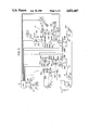
- FIG. 3 illustrates the details of the automatic shift mechanism shown in FIG. 1 having the shift actuator of FIG. 2 as a component thereof.
- the throttle actuator 1 includes a spring 102 interposed between two arms 101a, 101b pivotally supported at their respective centers.
- the accelerator pedal 3 is coupled to one end of one arm 101a by a wire 103a, and the end of the other arm 101b on the side opposite the abovementioned end of the arm 101a is coupled to the throttle of the engine 2 by a wire 103b.
- the arms 101a, 101b are swung in unison by the spring 102 in response to depression of the accelerator pedal 2, whereby the throttle is opened or closed.
- a plate 105a which is mounted in a case 104a by a diaphragm so as to be capable of moving freely, is coupled by a chain 106a to the end of the arm 101a opposite the wire 103a.
- the interior of the case 104a is partitioned into a pressure chamber 107a and a chamber 107'a by the plate 105a and the diaphragm.
- a spring 108a is interposed between the plate 105a and the inner wall of the case 104a within the pressure chamber 107a, and the chamber 107'a is in communication with the atmosphere.
- a plate 105b which, together with a diaphragm, partitions the interior of a case 104b into a pressure chamber 107b and a chamber 107'b, is coupled by a chain 106b to the end of arm 101b opposite the wire 103b, and spring 108b is loaded in the pressure chamber 107b.
- the pressure chambers 107a, 107b are connected to the vacuum pump 21 by solenoid valves 109a, 109b, respectively.
- the solenoid valves 109a, 109b are adapted to communicate the pressure chambers 107a, 107b with the vacuum pump 21 (as a vacuum source) or the atmosphere in a switching manner. Operation of these solenoid valves is controlled by the CPU 6.
- a pressure regulating valve 110 Connected between the solenoid vlves 109a, 109b and the vacuum pump 21 are a pressure regulating valve 110, a check valve 111 and a vacuum tank 112.
- Numeral 200 denotes a manual shift arm so adapted that a fork shaft 202 is operated by manipulation of a shift lever 201 to enable a shift to reverse and to first through third forward speeds.
- a fork shaft 203 for fourth and fifth speeds is coupled to a shift rod 205 by a lever 204 pivotally supported at its central portion, with the arrangement being such that a shift is effected between fourth and fifth speeds by rocking the lever 204.
- An actuator 206 having pressure chambers 206A, 206B defined by a diphragm 206C fixed to a rod 205 is attached to one end of the shift rod 205.
- a neutral return spring 207 for holding the shift rod at the neutral position is attached to the other end of the shift rod 205.
- the pressure chambers 206A, 206B of the actuator 206 are connected to the vacuum pump 21 via a fourth-speed solenoid valve 208A and a fifth-speed solenoid valve 208B, respectively.
- the solenoid valves 208A, 208B, the operation whereof is controlled by the CPU 6, are adapted to communicate the pressure chambers 206A, 206B with the vacuum pump 21 or the atmosphere in a switching manner.
- Connected between the solenoid valves 208A, 208B and the vacuum pump 21 are a pressure regulating valve 209, a check valve 210 and a vacuum tank 211.
- the shift rod 205 is provided with a fourth-speed switch 212 and a fifth-speed switch 213 for detecting when the shift rod 205 is slid to the fourth-speed position or fifth-speed position by operation of the actuator 206, and for supplying the CPU 6 with signals indicative of which of these positions the shift rod 205 occupies.
- a fourth-speed select switch 214 inputs a fourth-speed shift signal to the CPU 6 when the shift lever 201 is shifted to the fourth-speed position.
- Numeral 215 denotes a feeling unit which functions when a shift is made to the fourth-speed position.
- Numeral 9 denotes a vehicle velocity sensor mounted on the transmission, 217 a fifth-speed indicator lamp, 218 a gear-shift chime, and 219 a mode switch.
- the fourth-speed lever switch 214 When the shift lever 201 is placed in the fourth-speed shift position, the fourth-speed lever switch 214 is turned on and produces a signal on the basis of which the CPU 6 turns on the fourth-speed solenoid valve 208A (step a) to communicate the pressure chamber 206A of actuator 206 with the vacuum pump 21, thereby bringing the pressure chamber to negative pressure.
- the shift rod 205 is slid to the left in FIG. 3, so that the fork shaft 203 is moved to the fourth-speed side via the lever 204, whereby an up-shift to fourth speed is made.
- the plate 221, engaging with the nut 205d comes out of the plug 222 to compress the spring 207 as shown in FIG. 6.
- This up-shift to fourth speed is sensed by the CPU 6. This is accomplished by a signal which the fourth-speed switch 212 inputs to the CPU 6 upon sensing the sliding of the shift rod 205 to the fourth-speed side (step b).
- the CPU issues a command in response to which the solenoid valve (low-throttle solenoid valve) 109b is turned on, the fourth-speed solenoid valve 208A is turned off and the fifth-speed solenoid valve 208B is turned on (step d).
- the solenoid valve low-throttle solenoid valve
- the pressure chamber 107b is evacuated to negative pressure by being communicated with the vacuum pump 21, so that the chain 106b is pulled to rotate the arm 101b in the direction of arrow A in FIG. 3, thereby reducing the throttle opening of the engine 2.
- the pressure chamber 206B of actuator 206 is now brought to negative pressure by being communicated with the vacuum pump 21, so that the shift rod 205 is urged rightward in FIG. 3.
- the fork shaft 203 slips from fourth speed to neutral, the shift rod 205 is slid to the neutral position shown in FIG. 3, and the synchro is pressued against the fifth-speed gear.
- the synchro acts in fifth speed, as a result of which the shift rod 205 slides further to the right in FIG. 7 to be situated at the fifth-speed position.
- step h when the fifth-speed solenoid valve 208B is turned on, the vehicle is decelerated from the overdrive traveling state (step h), the vehicle velocity V drops below the prescribed velocity V 2 and, moreover, the acceleration opening ⁇ exceeds the prescribed opening ⁇ 2 (step i), the CPU 6 issues commands to turn on both the solenoid valves 109a, 109b, turn on the fourth-speed solenoid valve 208A and turn off the fifth-speed solenoid valve 208B (step j).
- the throttle opening is reduced by the rotation of the arm 101b in response to turn-on of the solenoid valve (low-throttle solenoid valve) 109b.
- the fourth-speed solenoid valve 208A is turned on to establish negative pressure in the pressure chamber 206A and, hence, urge the shift rod 205 leftward in FIG. 5.
- the shift slips from fifth speed to neutral and the synchro is pressed against the fourth-speed gear.
- the fifth-speed switch 213 is turned off (step k) by sliding of the shift rod 205, in response to which the CPU 6 turns off the solenoid valve 109b (step 1) to open the throttle.
- the synchro comes into play in fourth speed to effect the down-shift to fourth speed.
- This down-shift to fourth speed is sensed by the fourth-speed switch 202, which turns on (step m).
- the CPU 6 thereafter turns off the solenoid valve (half-throttle solenoid valve) 109a (step n) to complete the down-shift.
- the shift actuator for the fourth speed--fifth speed shift is operated by air pressure.
- this actuator it is also possible to operate this actuator by controlling hydraulic pressure or else.
- FIGS. 8 through 10 illustrate a noval shift reversing device of the shift actuator 10 coupled to the fourth speed--fifth speed shift actuator of FIG. 2.
- a shift-and-select lever shaft 11 is arranged inside a housing so as to be rotated about its central axis by manipulating the shift lever 201.
- a shift inner lever 12 fitted onto the shaft 11 rotates together with shaft 11 by virtue of splining or other means and is capable of moving in the axial direction of the shaft 11.
- the shift inner lever 12 has an arm 12a extending downwardly in FIG. 8, and an arm 12b extending leftward with an angle of about 90 degrees relative to the arm 12a.
- the distal end of the downwardly extending arm 12a is situated so as to be capable of engaging shift heads 202'a, 202a of a reverse--first speed fork shaft 202' and the second speed--third speed fork shaft 202, respectively.
- the distal end of the leftwardly extending arm 12b is situated in front of a recess 215b of a feeling lever 215a fitted so as to slide freely in the housing. The arrangement is such that the distal end of the arm 12b will fit into the recess 215b due to movement of the shift inner lever 12.
- two depressions 215c, 215d are formed on the side of the feeling lever 215a, and a ball detent 215f urged by a spring 215e is fitted under pressure in either the depression 215c or 215d.
- the fourth-speed select switch 214 is arranged at a position at the distal end of the shaft 11 and is turned on by being contacted by the shaft 11 when the latter is slid to the fourth-speed position.
- a shaft 13 is arranged in the housing so as to lie parallel to the shift-and-select shaft 11.
- Supported on the shaft 13 is a fourth speed--fifth speed lever 14 capable of rotating about its axis in unison with the shaft 13 and having an arm 14a extending downwardly in FIG. 8.
- the distal end of the downwardly extending arm 14a is in engagement with a shift head 203a of a fourth speed--fifth speed fork shaft 203 which performs a shifting operation.
- the lever 204 depicted in FIG. 2 is fitted securely on the end of shaft 13 opposite the side on which the fourth speed--fifth speed lever is attached.
- the distal end portion of the lever 204 is engaged with the head 205a of the shift rod 205, as mentioned above.
- the distal end of the arm 12a will be in engagement with the shift head 202a of the fork shaft 202 for the second and third speeds, and the other arm 12b will be free (see FIG. 9).
- the shift inner lever 12 is shifted in the direction of arrow B under these condition, the fork shaft 202 moves rightward in FIG. 8 (i.e. in a direction for shifting to second speed).
- the shift inner lever 12 is shifted in the direction of arrow C in FIG. 8 on the other hand, the fork shaft 202 moves leftward in FIG. 8 (i.e. in a direction for shifting to third speed).
- a shift to second speed or third speed is achieved.
- a shift to first speed and reverse is achieved by sliding the shift inner lever 12 in the direction of arrow B in FIG. 9 (to the position indicated by the dsahed line ⁇ ) and then turning the lever 12 in either direction, just as in shifting to second speed or third speed as described above.
- the shift inner lever 12 When the shift lever 201 is shifted to the fourth-speed shift position, the shift inner lever 12 is slid in the direction of arrow D in FIG. 9 together with the shaft 11, so that the arm 12a separates from the shift head 202a (to occupy the position indicated by the dashed line ⁇ ) and the arm 12b is fitted into the recess 215b of feeling lever 215a.
- the feeling lever 215a slides so that the ball detent 215f gets unseated from the depression 215c and then seated in the depression 215d. This phenomenon is felt by the driver, who is thereby capable of sensing the shift to fourth speed.
- the shift rod 205 is slid in the fourth-speed direction, as mentioned earlier, so that the fourth--fifth speed fork shaft 203 is slid to the fourth-speed side via the lever 204, shaft 13, fourth--fifth speed lever 14 and fourth--fifth speed shift head 203a, thereby effecting the shift to fourth speed.
- the shift to fifth speed is performed automatically by sliding the shift rod 205 by means of the actuator 206 in the direction opposite that for the fourth-speed shift, as set forth above.
Landscapes
- Engineering & Computer Science (AREA)
- Chemical & Material Sciences (AREA)
- Combustion & Propulsion (AREA)
- Mechanical Engineering (AREA)
- Transportation (AREA)
- General Engineering & Computer Science (AREA)
- Automation & Control Theory (AREA)
- Physics & Mathematics (AREA)
- Fluid Mechanics (AREA)
- Gear-Shifting Mechanisms (AREA)
- Control Of Transmission Device (AREA)
Applications Claiming Priority (2)
| Application Number | Priority Date | Filing Date | Title |
|---|---|---|---|
| JP61-300157 | 1986-12-18 | ||
| JP61300157A JPS63158346A (ja) | 1986-12-18 | 1986-12-18 | 歯車式トランスミツシヨンの自動シフト機構におけるシフトアクチユエ−タ |
Publications (1)
| Publication Number | Publication Date |
|---|---|
| US4821607A true US4821607A (en) | 1989-04-18 |
Family
ID=17881429
Family Applications (1)
| Application Number | Title | Priority Date | Filing Date |
|---|---|---|---|
| US07/134,192 Expired - Fee Related US4821607A (en) | 1986-12-18 | 1987-12-17 | Shift acutator in automatic shift mechanism of geared transmissions |
Country Status (2)
| Country | Link |
|---|---|
| US (1) | US4821607A (ja) |
| JP (1) | JPS63158346A (ja) |
Cited By (11)
| Publication number | Priority date | Publication date | Assignee | Title |
|---|---|---|---|---|
| US4998444A (en) * | 1987-07-16 | 1991-03-12 | Automotive Products (Usa) Inc. | Control system for electric shift apparatus |
| US5014038A (en) * | 1987-09-14 | 1991-05-07 | Automotive Products (Usa) Inc. | Motor vehicle control system |
| US5021764A (en) * | 1989-03-15 | 1991-06-04 | Automotive Products (Usa) Inc. | Diagnostics for electronic transmission control system |
| US5035158A (en) * | 1989-09-25 | 1991-07-30 | Automotive Products (Usa) Inc. | Electric shift and transfer case apparatus with control system therefore |
| US5042133A (en) * | 1989-03-15 | 1991-08-27 | Automotive Products (Usa) Inc. | Testing method for electric shift control apparatus |
| EP0651183A2 (en) * | 1993-11-03 | 1995-05-03 | Dana Corporation | Vehicle transmission having manually shifted lower gears and automatically shifted higher gears |
| US5476021A (en) * | 1993-03-31 | 1995-12-19 | Mercedes-Benz Ag | Motor vehicle toothed change transmission shift device |
| GB2324344A (en) * | 1997-04-18 | 1998-10-21 | Atlas Fahrzeugtechnik Gmbh | Actuator and indexing arrangements for automatic transmission |
| US20030100402A1 (en) * | 2001-11-28 | 2003-05-29 | Joung-Chul Kim | Select-shock control system and method for automotive automatic transmission |
| US6658951B2 (en) * | 2001-02-12 | 2003-12-09 | Luk Lamellen Und Kupplungsbau Beteiligungs Kg | Hydraulic actuation systems |
| US20040211276A1 (en) * | 2003-04-24 | 2004-10-28 | Katsuhiko Ito | Shift position detection apparatus for variable speed gear |
Families Citing this family (1)
| Publication number | Priority date | Publication date | Assignee | Title |
|---|---|---|---|---|
| JP4606197B2 (ja) * | 2005-02-22 | 2011-01-05 | 株式会社クボタ | シフトフォークの操作装置 |
Citations (10)
| Publication number | Priority date | Publication date | Assignee | Title |
|---|---|---|---|---|
| FR879841A (fr) * | 1939-04-20 | 1943-03-05 | Bendix Westinghouse Automotive | Dispositif de changement de vitesse |
| US2399567A (en) * | 1943-08-21 | 1946-04-30 | Carl D Peterson | Control system for change-speed transmission gearing |
| US2522228A (en) * | 1946-03-18 | 1950-09-12 | Bendix Aviat Corp | Transmission control mechanism |
| US2548761A (en) * | 1947-03-26 | 1951-04-10 | Borg Warner | Transmission interlock mechanism |
| US3530668A (en) * | 1968-03-30 | 1970-09-29 | Gunter Siebers | Rapid gear-change apparatus |
| US3688609A (en) * | 1970-11-12 | 1972-09-05 | Borg Warner | Overdrive electronic control system |
| US4023443A (en) * | 1972-12-15 | 1977-05-17 | Nissan Motor Co., Ltd. | Transmission synchronizing mechanism |
| US4266447A (en) * | 1978-11-09 | 1981-05-12 | Robert Bosch Gmbh | Apparatus and method for improving the jolt control in a motor vehicle drive system |
| US4520694A (en) * | 1981-12-24 | 1985-06-04 | Robert Bosch Gmbh | Method of controlling engine operation in an automotive vehicle during gear change |
| US4662242A (en) * | 1985-11-01 | 1987-05-05 | Borg-Warner Automotive, Inc. | Transaxle with multi-stage final drive assembly |
Family Cites Families (1)
| Publication number | Priority date | Publication date | Assignee | Title |
|---|---|---|---|---|
| JPS6148648A (ja) * | 1984-08-10 | 1986-03-10 | Toyota Motor Corp | 車両用歯車変速機の操作機構 |
-
1986
- 1986-12-18 JP JP61300157A patent/JPS63158346A/ja active Pending
-
1987
- 1987-12-17 US US07/134,192 patent/US4821607A/en not_active Expired - Fee Related
Patent Citations (10)
| Publication number | Priority date | Publication date | Assignee | Title |
|---|---|---|---|---|
| FR879841A (fr) * | 1939-04-20 | 1943-03-05 | Bendix Westinghouse Automotive | Dispositif de changement de vitesse |
| US2399567A (en) * | 1943-08-21 | 1946-04-30 | Carl D Peterson | Control system for change-speed transmission gearing |
| US2522228A (en) * | 1946-03-18 | 1950-09-12 | Bendix Aviat Corp | Transmission control mechanism |
| US2548761A (en) * | 1947-03-26 | 1951-04-10 | Borg Warner | Transmission interlock mechanism |
| US3530668A (en) * | 1968-03-30 | 1970-09-29 | Gunter Siebers | Rapid gear-change apparatus |
| US3688609A (en) * | 1970-11-12 | 1972-09-05 | Borg Warner | Overdrive electronic control system |
| US4023443A (en) * | 1972-12-15 | 1977-05-17 | Nissan Motor Co., Ltd. | Transmission synchronizing mechanism |
| US4266447A (en) * | 1978-11-09 | 1981-05-12 | Robert Bosch Gmbh | Apparatus and method for improving the jolt control in a motor vehicle drive system |
| US4520694A (en) * | 1981-12-24 | 1985-06-04 | Robert Bosch Gmbh | Method of controlling engine operation in an automotive vehicle during gear change |
| US4662242A (en) * | 1985-11-01 | 1987-05-05 | Borg-Warner Automotive, Inc. | Transaxle with multi-stage final drive assembly |
Cited By (16)
| Publication number | Priority date | Publication date | Assignee | Title |
|---|---|---|---|---|
| US4998444A (en) * | 1987-07-16 | 1991-03-12 | Automotive Products (Usa) Inc. | Control system for electric shift apparatus |
| US5014038A (en) * | 1987-09-14 | 1991-05-07 | Automotive Products (Usa) Inc. | Motor vehicle control system |
| US5021764A (en) * | 1989-03-15 | 1991-06-04 | Automotive Products (Usa) Inc. | Diagnostics for electronic transmission control system |
| US5042133A (en) * | 1989-03-15 | 1991-08-27 | Automotive Products (Usa) Inc. | Testing method for electric shift control apparatus |
| US5035158A (en) * | 1989-09-25 | 1991-07-30 | Automotive Products (Usa) Inc. | Electric shift and transfer case apparatus with control system therefore |
| US5476021A (en) * | 1993-03-31 | 1995-12-19 | Mercedes-Benz Ag | Motor vehicle toothed change transmission shift device |
| EP0651183A2 (en) * | 1993-11-03 | 1995-05-03 | Dana Corporation | Vehicle transmission having manually shifted lower gears and automatically shifted higher gears |
| EP0651183A3 (en) * | 1993-11-03 | 1997-01-08 | Dana Corp | Vehicle transmission with manual control for the gearshift and automatic selection for the gearshift. |
| GB2324344A (en) * | 1997-04-18 | 1998-10-21 | Atlas Fahrzeugtechnik Gmbh | Actuator and indexing arrangements for automatic transmission |
| US5997432A (en) * | 1997-04-18 | 1999-12-07 | Aft Atlas Fahrzeugtechnik | Automated transmission for use in power trains of motor vehicles |
| GB2324344B (en) * | 1997-04-18 | 2002-02-20 | Atlas Fahrzeugtechnik Gmbh | Automated transmission for use in power trains of motor vehicles |
| US6658951B2 (en) * | 2001-02-12 | 2003-12-09 | Luk Lamellen Und Kupplungsbau Beteiligungs Kg | Hydraulic actuation systems |
| US20030100402A1 (en) * | 2001-11-28 | 2003-05-29 | Joung-Chul Kim | Select-shock control system and method for automotive automatic transmission |
| US6827667B2 (en) * | 2001-11-28 | 2004-12-07 | Hyundai Motor Company | Select-shock control system and method for automotive automatic transmission |
| US20040211276A1 (en) * | 2003-04-24 | 2004-10-28 | Katsuhiko Ito | Shift position detection apparatus for variable speed gear |
| US7104150B2 (en) * | 2003-04-24 | 2006-09-12 | Honda Motor Co., Ltd. | Shift position detection apparatus for variable speed gear |
Also Published As
| Publication number | Publication date |
|---|---|
| JPS63158346A (ja) | 1988-07-01 |
Similar Documents
| Publication | Publication Date | Title |
|---|---|---|
| US4821607A (en) | Shift acutator in automatic shift mechanism of geared transmissions | |
| US5357820A (en) | Shift control system for automatic vehicle transmission | |
| JPS5819898B2 (ja) | ジドウシヤギヤボツクス ノ ギヤキリカエセイギヨソウチ | |
| US5875680A (en) | Automatic forward/reverse gear change system having a main clutch disengaged and main vehicle brake engaged during a shuttle shift | |
| KR920000036B1 (ko) | 보조변속기 기어변경 조정장치 | |
| GB2214248A (en) | Ratio selector system using fluid actuators and ectrohydraulic control in a vehicle transmission | |
| US4250923A (en) | Shift actuator for a multi-speed transmission | |
| CA1055806A (en) | Engine and transmission control system | |
| US4142614A (en) | Hydraulic transmission control system | |
| US4825831A (en) | Throttle actuator in automatic shift mechanism of geared transmissions | |
| US5846160A (en) | Power transmission control | |
| WO1990004225A1 (en) | Gear selector device for a vehicle gearbox | |
| JPS6234214A (ja) | ギア・チエンジ・レバ−・ユニツト | |
| JPH0532629B2 (ja) | ||
| JPH01120476A (ja) | 車両用無段変速機の変速制御装置 | |
| CA2071404A1 (en) | Electro-hydraulic shift interlock apparatus for an automatic transmission | |
| US4358988A (en) | Control elements for gearbox ratio selectors in heavy vehicles | |
| JPS6137499B2 (ja) | ||
| US2581291A (en) | Preselective transmission control | |
| JP4655482B2 (ja) | 作業車両の変速装置 | |
| KR20090065282A (ko) | 이중 조작이 가능한 클러치 릴리스 포크 어셈블리 및 그방법 | |
| JP2832675B2 (ja) | 変速制御装置 | |
| USRE23901E (en) | T randol | |
| JPS641124U (ja) | ||
| JPH0543321Y2 (ja) |
Legal Events
| Date | Code | Title | Description |
|---|---|---|---|
| AS | Assignment |
Owner name: AISIN SEIKI KABUSHIKI KAISHA, 1, ASAHI-MACHI 2-CHO Free format text: ASSIGNMENT OF ASSIGNORS INTEREST.;ASSIGNOR:KAWAI, SHUNICHI;REEL/FRAME:004846/0302 Effective date: 19880215 Owner name: AISIN SEIKI KABUSHIKI KAISHA,JAPAN Free format text: ASSIGNMENT OF ASSIGNORS INTEREST;ASSIGNOR:KAWAI, SHUNICHI;REEL/FRAME:004846/0302 Effective date: 19880215 |
|
| FEPP | Fee payment procedure |
Free format text: PAYOR NUMBER ASSIGNED (ORIGINAL EVENT CODE: ASPN); ENTITY STATUS OF PATENT OWNER: LARGE ENTITY |
|
| REMI | Maintenance fee reminder mailed | ||
| LAPS | Lapse for failure to pay maintenance fees | ||
| FP | Lapsed due to failure to pay maintenance fee |
Effective date: 19930418 |
|
| STCH | Information on status: patent discontinuation |
Free format text: PATENT EXPIRED DUE TO NONPAYMENT OF MAINTENANCE FEES UNDER 37 CFR 1.362 |