US4725298A - Method for making low pressure mercury vapor discharge lamp - Google Patents
Method for making low pressure mercury vapor discharge lamp Download PDFInfo
- Publication number
- US4725298A US4725298A US06/861,724 US86172486A US4725298A US 4725298 A US4725298 A US 4725298A US 86172486 A US86172486 A US 86172486A US 4725298 A US4725298 A US 4725298A
- Authority
- US
- United States
- Prior art keywords
- bulb
- glass
- glass tubes
- tubes
- end plate
- Prior art date
- Legal status (The legal status is an assumption and is not a legal conclusion. Google has not performed a legal analysis and makes no representation as to the accuracy of the status listed.)
- Expired - Lifetime
Links
- QSHDDOUJBYECFT-UHFFFAOYSA-N mercury Chemical compound [Hg] QSHDDOUJBYECFT-UHFFFAOYSA-N 0.000 title claims abstract description 14
- 238000000034 method Methods 0.000 title abstract description 8
- 239000011521 glass Substances 0.000 claims abstract description 163
- 238000004891 communication Methods 0.000 claims abstract description 12
- 239000006060 molten glass Substances 0.000 claims abstract description 8
- 230000002093 peripheral effect Effects 0.000 claims abstract description 7
- 230000004927 fusion Effects 0.000 claims abstract 3
- 238000004519 manufacturing process Methods 0.000 claims description 28
- 238000010438 heat treatment Methods 0.000 claims description 7
- 239000000853 adhesive Substances 0.000 description 32
- 230000001070 adhesive effect Effects 0.000 description 32
- 239000008188 pellet Substances 0.000 description 10
- 239000000919 ceramic Substances 0.000 description 9
- 238000003780 insertion Methods 0.000 description 9
- 230000037431 insertion Effects 0.000 description 9
- 239000011248 coating agent Substances 0.000 description 7
- 238000000576 coating method Methods 0.000 description 7
- 238000007789 sealing Methods 0.000 description 6
- 238000010276 construction Methods 0.000 description 5
- 238000005452 bending Methods 0.000 description 4
- 238000010586 diagram Methods 0.000 description 4
- 238000007599 discharging Methods 0.000 description 4
- 230000000694 effects Effects 0.000 description 4
- 230000005489 elastic deformation Effects 0.000 description 4
- 239000000463 material Substances 0.000 description 4
- 238000002360 preparation method Methods 0.000 description 4
- 238000001035 drying Methods 0.000 description 3
- 229910052839 forsterite Inorganic materials 0.000 description 3
- 238000007689 inspection Methods 0.000 description 3
- HCWCAKKEBCNQJP-UHFFFAOYSA-N magnesium orthosilicate Chemical compound [Mg+2].[Mg+2].[O-][Si]([O-])([O-])[O-] HCWCAKKEBCNQJP-UHFFFAOYSA-N 0.000 description 3
- 238000012423 maintenance Methods 0.000 description 3
- 238000002844 melting Methods 0.000 description 3
- 230000008018 melting Effects 0.000 description 3
- 229910052751 metal Inorganic materials 0.000 description 3
- 239000002184 metal Substances 0.000 description 3
- 238000000465 moulding Methods 0.000 description 3
- 239000010953 base metal Substances 0.000 description 2
- 238000009792 diffusion process Methods 0.000 description 2
- MLFHJEHSLIIPHL-UHFFFAOYSA-N isoamyl acetate Chemical compound CC(C)CCOC(C)=O MLFHJEHSLIIPHL-UHFFFAOYSA-N 0.000 description 2
- 239000005355 lead glass Substances 0.000 description 2
- 238000007493 shaping process Methods 0.000 description 2
- 239000005361 soda-lime glass Substances 0.000 description 2
- 238000012360 testing method Methods 0.000 description 2
- 239000000020 Nitrocellulose Substances 0.000 description 1
- NBLJZMMOKBGGOW-UHFFFAOYSA-N [Pb]=O.B(O)(O)O Chemical compound [Pb]=O.B(O)(O)O NBLJZMMOKBGGOW-UHFFFAOYSA-N 0.000 description 1
- 230000006835 compression Effects 0.000 description 1
- 238000007906 compression Methods 0.000 description 1
- 238000005520 cutting process Methods 0.000 description 1
- 238000013461 design Methods 0.000 description 1
- 239000000428 dust Substances 0.000 description 1
- 238000012840 feeding operation Methods 0.000 description 1
- 229940117955 isoamyl acetate Drugs 0.000 description 1
- 238000011031 large-scale manufacturing process Methods 0.000 description 1
- WABPQHHGFIMREM-UHFFFAOYSA-N lead(0) Chemical compound [Pb] WABPQHHGFIMREM-UHFFFAOYSA-N 0.000 description 1
- ZPPSOOVFTBGHBI-UHFFFAOYSA-N lead(2+);oxido(oxo)borane Chemical compound [Pb+2].[O-]B=O.[O-]B=O ZPPSOOVFTBGHBI-UHFFFAOYSA-N 0.000 description 1
- 229940052609 legend Drugs 0.000 description 1
- 238000002156 mixing Methods 0.000 description 1
- 229920001220 nitrocellulos Polymers 0.000 description 1
- 239000000843 powder Substances 0.000 description 1
- 238000004080 punching Methods 0.000 description 1
- 238000009877 rendering Methods 0.000 description 1
Images


Classifications
-
- H—ELECTRICITY
- H01—ELECTRIC ELEMENTS
- H01J—ELECTRIC DISCHARGE TUBES OR DISCHARGE LAMPS
- H01J61/00—Gas-discharge or vapour-discharge lamps
- H01J61/02—Details
- H01J61/30—Vessels; Containers
- H01J61/32—Special longitudinal shape, e.g. for advertising purposes
- H01J61/327—"Compact"-lamps, i.e. lamps having a folded discharge path
-
- H—ELECTRICITY
- H01—ELECTRIC ELEMENTS
- H01J—ELECTRIC DISCHARGE TUBES OR DISCHARGE LAMPS
- H01J9/00—Apparatus or processes specially adapted for the manufacture, installation, removal, maintenance of electric discharge tubes, discharge lamps, or parts thereof; Recovery of material from discharge tubes or lamps
- H01J9/24—Manufacture or joining of vessels, leading-in conductors or bases
- H01J9/26—Sealing together parts of vessels
Definitions
- the present invention relates to a low pressure mercury vapor discharge lamp provided with a bulb for forming an electric discharging path and preparation thereof.
- a fluorescent lamp such as a low pressure mercury vapor discharge lamp provided with a U-shaped bulb formed with bending or connecting processes
- a publication such as Japanese Unexamined Patent Publication No. 155675/1979 (FIG. 1) or Japanese Unexamined Patent Publication No. 133744/1980 (FIG. 2).
- the fluorescent lamp having such construction is advantageous because a lamp is made in a compact form.
- the U-shaped bulb 1 as shown in the figure has a space of gap 31 between both legs 1a, 1b. Therefore, in manufacturing steps, when the legs 1a, 1b of the bulb 1 are gripped from their outer sides so that a force is applied in its central direction, a connecting part 2a between the both legs 1a, 1b is apt to cause breakage.
- a device A is generally used to grip the both legs 1a, 1b of the bulb 1 in a plan passing through the legs 1a, 1b, as shown in FIG. 3 which is disclosed in Japanese Unexamined Patent Publication No. 124928/1980.
- the fluorescent lamp in a compact form which is substituted for an incandescent lamp generally has the legs 1a, 1b of the bulb 1 of about 100-150 mm in height, on account of which the bulb has to be supported in only one direction in the manufacturing steps. This means that it is necessary to prepare the device A used for various manufacturing steps at a high accuracy thereby to cause problems of complicated maintenance and inspection.
- FIG. 4 shows a lamp, as an example, disclosed in Japanese Unexamined Patent Publication No. 108162/1980.
- two U-shaped bulbs 1, 1 are arranged so that there remain spaces of gap 31, 32, 33 and 34 between all adjoining legs among the legs 1a, 1b, 1c and 1d.
- the present invention has been attained in view of the above-mentioned circumstances and it is an object of the present invention to provide a low pressure mercury vapor discharge lamp enabling a bulb to be easily gripped by a supporting device in manufacturing steps, simplifying a manufacturing device, rendering maintenance and inspection to be easy and allowing a large scale poduction, by arranging legs of a U-shaped bulb in a contacting state.
- FIGS. 1 and 2 are respectively front views of conventional U-shaped fluorescent lamps
- FIG. 3 is a perspective view showing how U-shaped bulb is gripped by a device in manufacturing steps
- FIG. 4 is a perspective view of a conventional double U-shaped fluorescent lamp
- FIG. 5 is a front view partly cross-sectioned of an embodiment of the U-shaped bulb according to the present invention.
- FIG. 6 is a perspective view showing another embodiment of the present invention.
- FIG. 7 is a schematic view of the bulb shown in FIG. 6 in a developed state
- FIG. 8 is a plan view of the bulb shown in FIG. 6;
- FIG. 9 is a developed view of another embodiment of the lamp according to the present invention.
- FIG. 10 is a developed view of still another embodiment of the present invention.
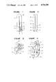
- FIGS. 11 and 12 are enlarged cross-sectional view of an important part of another embodiment of the present invention.
- FIGS. 13 to 16 are respectively enlarged cross-sectional view of the other embodiments of the present invention.
- FIG. 17 is a perspective view partly cross-sectioned of another embodiment of the present invention.
- FIG. 18 is a perspective view of still another embodiment of the present invention in which a part of an outer bulb is broken and a part of bulb is cross-sectioned;
- FIG. 19 is a perspective view in a disassembled state of another embodiment of the present invention.
- FIG. 20 is an enlarged cross-sectional view partly omitted of the bulb shown in FIG. 19;
- FIG. 21 is a plan view of a part of the lamp shown in FIG. 19;
- FIG. 22 is a perspective view in a disassembled state of another embodiment of the present invention.
- FIG. 23 is a perspective view of an end plate in FIG. 22;
- FIG. 24 is a perspective view in a disassembled state of further embodiment of the present invention.
- FIG. 25 is a perspective view of an end plate of another embodiment of the present invention.
- FIG. 26 is a cross-sectional view of the end plate
- FIG. 27 is a cross-sectional view of another embodiment of the present invention.
- FIG. 28 is a perspective view in a disassembled state of another embodiment of the present invention.
- FIG. 29 is a cross-sectional view showing a coating step of the end plate shown in FIG. 27;
- FIG. 30 is a diagram showing a drying process for the end plate shown in FIG. 27;
- FIGS. 31 and 32 are respectively diagrams showing solidifying steps of glass frit shown in FIG. 27;
- FIG. 33 is an enlarged perspective view showing another embodiment of the present invention.
- FIG. 34 is a perspective view in a disassembled state of another embodiment of the present invention.
- FIGS. 35 to 42 are diagrams showing an example of preparation of U-shaped glass tube
- FIG. 43 is a perspective view in a disassembled state of a splitable mold.
- FIGS. 44 to 46 are diagrams showing another example of preparation of a double U-shaped glass tube by using single U-shaped glass tubes.
- FIG. 5 is a front view partly omitted on an embodiment of the U-shaped fluorescent lamp according to the present invention.
- a reference numeral 1 designates a U-shaped bulb formed by juxtaposing two linear tubes of soda-line glass of 16.5 mm in outer diameter and 0.8 mm thick and connecting each one end so that the interior of the tubes is communicated with each other while keeping air-tightness to the outside.
- the heightness of thus obtained bulb 1 is 140 mm.
- Both the legs 1a, 1b of the bulb 1 are substantially in close contact with each other to constitute a contacting state.
- the contacting state referred in the specification means that a space of gap 31 between the end part 1a' of the leg 1a and the end part 1b' of the leg 1b of the bulb 1 is in the range of 0-0.8 mm.
- a force is applied to both the end parts 1a', 1b' toward the gap 31 from the outside, namely, when a force is applied to the both legs 1a, 1b from the side of plane perpendicular to a plane passing between the legs 1a, 1b
- a tensile stress is applied to the connecting part 2a of the bulb 1 to cause elastic deformation in the connecting part 2a.
- a reference numeral 4 designates fluorescent layer
- a numeral 5 designates 5 a stem
- a numeral 6 designates electrodes
- a numeral 7 designates a base metal
- a numeral 8 designates a base metal pin
- a numeral 9 designates an adhesive
- a numeral 10 designates an end plate, all of which are the same as those used in the conventional lamp as shown in FIGS. 1 to 4.
- the both legs 1a, 1b of the bulb 1 are brought into a contacting state before the connecting part 2a exceeds limitation of the elastic deformation even though the elastic deformation is resulted in the connecting part 2a by a force applied to the both legs 1a, 1b toward the central part of them. Accordingly, the contacting part can resist against an external force applied after the legs have been contacted with each other to thereby avoid breakage of the connecting part 2a.
- the construction of the embodiment utilizes property of glass that it withstands compression stress although glass is apt to break against tensile stress.
- FIGS. 6 to 8 show another embodiment of the present invention in which FIG. 6 is a perspective view, FIG. 7 is a developed view and FIG. 8 is a plan view.
- numerals 1, 1 designate two U-shaped glass tubes, each being similar to that as shown in FIG. 5, in which they are integrally connected through a connecting part 2b which connects each one leg 1b, 1d of the both tubes so as to keep air-tightness to the atmosphere.
- the outer dimension of the U-shaped glass tubes is the same as that of FIG. 5 provided that the height of the tubes is 92 mm.
- the end parts 1a', 1b', 1c' and 1d' of the legs are sealingly bonded to a disc-like ceramic end plate 10 with an adhesive of glass frit. Further, the legs 1a, 1b of the bulb 1 and the legs 1c, 1d of the other bulb 1 are firmly connected to the end plate 10 in such a manner that the legs 1a, 1c and the legs 1b, 1d which are respectively ones of adjacent bulbs 1, 1, are opposed in a contacting state. Namely, gaps 31, 32, 33, 34 of mutually adjoining legs 1a, 1b, 1c, 1d are espectively in the range of 0-0.8 mm.
- an electrode 6 projects into each one end part 1a' or 1c' of the bulbs 1, 1 and each end part 1b' or 1d' without receiving therein an electrode 6 is sealingly connected with each other at a position near the end plate 10. Accordingly, a discharge path formed between the two electrodes 6 takes a course of one of the electrode 6 arranged in the leg end part 1a' of the bulb 1-the leg 1a-the leg 1b-the leg 1d-the leg 1c-the other electrode 6 arranged in the leg end part 1c' of the bulb.
- the fluorescent lamp having the construction as above-mentioned allows easiness of gripping of it in manufacturing steps, in addition that after completion of assemblage, breakage of the bulb 1 which may be caused when the lamp is attached to or detached from a lamp socket (not shown) is effectively prevented.
- the bulb 1 is gripped by an operator and a torque is applied to the bulb 1.
- a torque and a force bringing the U-shaped glass tubes in contact with each other are centralized to the leg end parts 1a'-1d' of the bulb 1 whereby breakage of the leg end parts 1a'-1d' often takes place.
- the legs 1a-1d can sufficiently withstand an external force which causes the legs to come in mutual contact. Further, because all the leg end parts 1a'-1d' are firmly connected to the end plate, the torque applied to the leg end parts 1a'-1d' is dispersed to reduce a risk of the breakage. In addition, this embodiment can be further in a compact form while elongate a discharge path and lamp efficiency can be further improved.
- a structure for preventing falling down of the bulb 1 is disclosed, for example, in Japanese Patent Aplication No. 213158/1982 which shows a lamp having a double tube structure.
- the glass bulb, the outer bulb and a glass stem can be simultaneously attached and solidified since the glass bulb can stand itself. Industrial merit obtained by such structure is great.
- the glass bulb shown in Japanese Patent Application No. 213158/1982 is formed in a double U-shape and the leg end portion at the side without receiving therein an electrode constitutes a curved portion which corresponds to the connecting part of this embodiment.
- U-shaped glass bulbs there is no limitation to use two U-shaped glass bulbs as in this embodiment but it may use more than two number of U-shaped glass bulbs with both legs which contain no electrode. In this case, when more than two number of U-shaped glass bulbs are arranged on the end plate so as to represent a polygon, it can impart an excellent design.
- Material for the end plate 10 may be any as far as it has the coefficient of expansion the same as or approximate to the glass bulb 1 beside ceramics.
- FIG. 9 is a developed view showing another embodiment of the present invention in which numerals 1, 1 designate double U-shaped bulbs formed in the same manner as that shown in FIGS. 6 to 8.
- a reference numeral 10 designates a end plate made of ceramics such as forsterite which is attached with a pair of electrodes 6 in sealing condition.
- the electrodes 6 are received respectively in the end parts 1a', 1c' of the serially connected bulbs 1, 1.
- the electrodes 6 are communicated each other so as not to cause electric discharge by bonding the end parts 1a', 1c' of the bulbs to the end plate 10 with an adhesive 11 of glass frit. End parts 1b', 1d' without receiving therein any electrode 6 are in contact with the end plate 10.
- the end plate 10 is provided at its part where the end parts 1b', 1d' are contacted a recess as an opening portion 12 through which the bulbs 1, 1 are communicated with the inner portion of an outer bulb 13.
- the outer bulb 13 is a cylindrical tube made of glass having the inner surface coated with a light diffusion layer 14 and having an opened bottom. The opened bottom of the outer bulb 13 is sealingly closed by the end plate 10 and an discharging medium is filled in the outer bulb to form a discharging space.
- the fluorescent lamp having the double tube structure as above-mentioned forms, in one hand, a double U-shaped electric discharge path as similar to the embodiment shown in FIGS. 6 to 8 and, on the other hand, causes the outer bulb 13 to form the mostly cooled part, whereby a mercury vapor pressure in the electric discharge space can be properly maintained to increase lamp efficiency.
- the outer configuration of the lamp can be in a compact form in comparison with the conventional lamp having a double tube structure.
- the lamp is so made that any external force is not applied to the bulbs after completion of assembleage, it is sufficient to bond only the leg end parts 1a', 1c' receiving therein electrodes 6 to the end plate 10 with the adhesive 11 of glass frit.
- the lamp is of a structure that when the bulbs 1, 1 are bonded to the end plate 10, the leg end parts 1a'-1d' formed integrally with each other by means of connecting parts 2a, 2b, 2a are to be brought into contact with the end plate 10. Accordingly, bonding operation can be satisfactorily conducted without requirement of any auxiliary means to support the bulbs 1, 1.
- the recess is formed in the end plate 10 to use it as the opening portion 12 in the embodiment shown in FIG. 9, the opening portion 12 can be an aperture formed at a part of the bulb 1 or formed by cutting an edge portion of a bulb 1 as shown in FIG. 10. It is always unnecessary to use two U-shaped bulbs 1 and use of single bulb 1 provides the same effect as the embodiment shown in FIGS. 9 and 10.
- FIGS. 11 and 12 This embodiment concerns how to connect an end plate 10 to a bulb 1.
- a reference numeral 1 designates a U-shaped bulb with both leg end parts 1a', 1b' opened.
- a pair of electrodes project from upper surface of the end plate 10, two pieces of adhesive 11 of glass frit in a form of ring the diameter of which is more or less smaller than the inner diameter of the opened leg end parts 1a', 1b' of the bulb are placed in such a manner that when the opened leg end parts 1a', 1b' of the bulb are mounted on the end plate 10 so as to surround each of the electrodes 6, the adhesive 11 respectively correspond to the inner walls 1a' 1 , 1b' 1 of the opened leg end parts 1a', 1b'.
- a reference numeral 14 designates a discharge tube. Then, the opened leg end parts 1a', 1b' of the bulb are placed on the end plate 10 containing therein each of the electrodes and glass frits 11. Two pieces of the adhesive 11 of glass frit are heated to be molten to thereby accomplish sealing the bulb 1 to the end plate 10.
- FIG. 12 shows condition of the bulb and the end plate sealed by heating.
- the inner walls 1a' 1 , 1b' 1 of the opened leg end parts 1a', 1b' of the bulb block prevent the molten adhesive from leaking out the outer circumferential edges of the opened leg end parts 1a', 1b'.
- the adhesive 11 of glass frit is applied to have a form of ring the diameter of which is more or less smaller than the inner diameter of the opened leg end parts 1a', 1b' of the bulb and accordingly, an amount of the adhesive to be applied can be reduced even if the adhesive is coated thicker, in comparison with a case that the end surfaces 1a' 3 , 1b' 3 of the opened leg end parts 1a', 1b' of the bulb are placed on the end plate 10 on which the adhesive 11 of glass frit is previously applied.
- a bulb 1 of 15 mm in inner diameter at open end and of 0.85 mm thick was prepared to compare an amount of the adhesive to be applied for this embodiment with the case in which the adhesive was previously applied.
- the amount of the adhesive for this embodiment is about 2.5 g for one lamp whereas 4.5 g for the other case.
- air-tightness between the atmosphere and the bulb 1 of the open leg end parts 1a', 1b' since the inner walls 1a' 1 , 1b' 1 are not contaminated with dust in comparison with the outer walls 1a' 2 , 1b' 2 , there takes place no problem of air-tightness.
- the length of the circle of the inner walls 1a' 1 , 1b' 1 is shorter than that the outer walls 1a' 2 , 1b' 2 , area for air-tightness is small. It is, therefore, advantageous in maintaining air-tightness.
- the opened leg end parts 1a', 1b' are mounted on the end plate having a flat surface whereby there is no risk of causing inclination of the bulb.
- the adhesive 11 of glass frit may be previously formed into a molded ring body having a diameter smaller than the inner diameter of the opened leg end parts 1a', 1b'.
- FIGS. 13 and 14 show other embodiments of the present invention.
- Glass frit fitting grooves 10a, 10b are respectively formed in an end plate 10; two pieces of adhesive 11 of glass frit previously molded into a ring form are respectively arranged in the fitting grooves 10a, 10b and the inner walls 1a' 1 , 1b' 1 of opened leg end parts 1a', 1b' are sealed by the adhesive.
- the ringed adhesive 11 of glass frit acts as a position determining member when the bulb 1 is sealed as shown in FIG. 13, in addition to many advantages as described in the foreign embodiments.
- determination of position can be easy since the bulb is received in the fitting grooves 10a, 10b.
- FIG. 15 shows still another embodiment. Projections 10c, 10d are formed in the end plate 10 to correspond to the inner diameter of the ringed adhesive 11 of glass frit and the ringed glass frit 11 is arranged around the projections 10c, 10d. The same effect as in the above-mentioned embodiment can be obtained in this embodiment.
- FIG. 16 shows a modified embodiment in which the electrode 6 is previously fitted to a flared glass stem 61. Use of this electrode allows simultaneously sealing of the stem 61 when the end plate 10 and the inner walls 1a' 1 , 1b' 1 of the opened leg end parts 1a', 1b' are sealed together.
- lamps having U-shaped bulb It is, however, not limited to a U-shape and it can be a shape as shown in FIG. 17.
- the bulb of the embodiments as above-mentioned can be applicable to a lamp having a double tube structure shown in FIG. 18 in which a bulb in a curbed form is arranged in a outer bulb 13 which provides a sealing space.
- a reference numeral 10 designates an end plate made of ceramics.
- a single glass frit fitting groove 10a having an oval recess which receives both leg end parts 1a', 1b' of a bulb described below.
- a pair of electrodes 6 is set up at a given position in the fitting groove 10a.
- the bulb 1 of a U-shape made of glass has both leg end parts 1a', 1b' and has the inner surface coated with a fluorescent layer 4.
- a reference numeral 11 designates an adhesive of glass frit and a numeral 14 designates a discharge tube.
- both the leg end parts 1a', 1b' of the bulb 1 are received in a common fitting groove 10a of the end plate 10 and are bonded thereto with the adhesive 11 of glass frit.
- the electrodes 6 are contained in the leg end parts 1a', 1b'.
- Soda-lime glass is used for the bulb 1; forsterite is used for the end plate 10 and a low melting point glass mainly consisting of boric acid-lead oxide is used for the glass frit 11 to bond the bulb and the end plate.
- both the leg end parts 1a', 1b' of the bulb 1 are firmly connected into a single common fitting groove 10a formed in the end plate 10. Accordingly, application of the adhesive 11 of glass frit to the fitting position groove 10a is carried out by squeezing out glass frit paste in a letter of 8; thus, a single continuous squeezing operation of the glass frit paste is satisfactory to coat the paste in the fitting groove 10a.
- a single fitting groove structure of the embodiment greatly reduces time for applying the glass frit paste in comparison with a structure in which fitting grooves are separately formed. Namely, in the single fitting groove structure, it is unnecessary to squeeze the glass frit into one fitting groove after having stopped the squeezing operation to a separate fitting groove, in other wards, it is unnecessary to repeat operations of dispense and stop.
- a single common fitting groove 10a makes a metallic mold for shaping the end plate 10 simple. Further, since the groove 10a has a broader common recess between both the leg end parts 1a', 1b' of the bulb 1, there takes place no unevenness in punched products when the end plate 10 is stamped whereby the ability of production is improved and the structure of the punching mold is simplified.
- an end plate 10 having a length of 40 mm, a width of 22 mm and a thickness of 4.5 mm in which the length, the width and the depth of an oval fitting groove 10a are respectively 36 mm, 18 mm and 1.5 mm was prepared and another end plate having the same dimensions as those of the end plate 10 provided that there are two fitting grooves each having an outer diameter of 18 mm and a depth of 1.5 mm was prepared as a reference.
- Time for squeezing-out and applying of glass frit paste is compared and it was found that time in this embodiment is 1.5 second per one end plate and time in the reference product is 3.5 second per one end plate.
- the end plate 10 prepared in accordance with this embodiment accomplished about 5% reduction in manufacturing cost of a metallic mold and about 7% increase in forming ability.
- a single U-shaped bulb 1 is used.
- a bulb 1 formed by integrally connecting a first U-shaped bulb and a second U-shaped bulb thereby having four legs 1a-1d can also be used as a lamp which provides an intensive light output without changing the total length of the bulb 1.
- the fitting groove for glass frit may be constructed in such a manner that there are formed a first fitting groove 10a for receiving both the leg end parts 1a', 1b' of the first U-shaped bulb and a second fitting groove 10b for receiving both the leg end parts 1c', 1d' of the second U-shaped bulb as shown in FIG.
- the dimension of the fitting grooves being determined depending on distance between the opened leg end parts 1a', 1 b' of the first and second bulbs and the length of a connecting part 2b between the first and second U-shaped bulbs.
- a reference numeral 10h designates insertion holes for electrodes.
- the fitting groove 10a for receiving glass frit may be provided with bulb contacting portions 10e with which each part of the outer surface 1a' 2 , 1b' 2 of the bulb are in contact.
- the bulb contacting portions 10e prevents the bulb from miss-fitting into the groove 10a or turning in the groove 10a when the bulb 1 is placed in the groove after having applied the adhesive 11 of glass frit to it.
- the bulb 1 of the present invention is applicable to a lamp having a double tube structure as shown in FIG. 27, in which the bulb is arranged as an inner tube in an outer bulb 13 which sealingly confine the inner tube to the atmosphere.
- Material for the end plate 10 can be selected from glass or metal other than ceramics.
- a reference numeral 1 designates a bulb consisting of two U-shaped glass tubes 1a, 1d made of soda-lime glass in which each one leg 1b', 1d' of the glass tubes is communicated with each other while keeping air tightness to the atmosphere and leg end parts 1b', 1d' of the bulbs are opened.
- a numeral 10 designates an end plate made of forsterite ceramics which is square in shape and sealingly closes the opened leg end parts 1a'-1d' of the bulb 1.
- grooves 10a-10d respectively receiving therein the opened leg-end parts 1a', 1d' of the bulb 1, stem inserting holes 10h for receiving stems, described below, which are respectively formed in the grooves 10a, 10c and an exhaust tube insertion hole 10j which is formed in one of the grooves 10a, are provided.
- the grooves 10a, 10c are adapted to receive the stems.
- Numerals 61 designate flared stems made of lead glass in which electrodes 6 are respectively sealingly attached and lead wires 62 and glass fine tubes 63 respectively extend outside from the stems.
- the diamter of a flared portion of the stems 61 is slightly smaller than the inner diameter of the glass tubes 1a, 1c of the bulb 1.
- a numeral 14 designates an exhaust tube made of lead glass.
- a flange-like enlarged diameter part 4b having a diameter greater than the exhaust tube insertion holes 10j is formed near the top end 14a of the exhaust tube 6 which is inserted in the bulb 1.
- a numeral 15 designates a pellet in a ring shape which is formed by molding glass frit as described below.
- a numeral 2b designates a connecting part for the bulbs 1b, 1d, and a numeral 4 designates a fluorescent layer coated on the inner surface of the bulb 1.
- a glass frit 11 in past form is previously prepared by mixing glass frit powder consisting of lead borate as a main component (such as IWF-T029 (tradename) manufactured by Iwaki Glass K.K. and a vehicle (obtained by dissolving nitrocellulose in isoamyl acetate).
- the glass frit as an adhesive 11 is coated in the grooves 10a, 10b formed in the upper surface of the end plat 10 as shown in FIG. 29.
- the end plate 10 is put in a tunnel type dry furnace D as shown in FIG. 30 and is dried at a temperature of about 150° C. for 15 minutes to dry the vehicle in the glass frit as the adhesive 11.
- the exhaust tube 14 is inserted into the exhaust tube insertion hole 10j formed in the groove 10b of the end plate 10 and then, the pellet 5 is put onto the top end 14a of the discharge tube 14.
- the stems 61 are respectively put on the grooves 10a, 10c of the end plate 10 while the lead wires 62 and glass fine tubes 63 are respectively inserted into the lead wire inserting holes 10h, 10h.
- FIGS. 31 shows condition that operations as stated in items 3, 4, 5 have been completed.
- a symbol B designates an end plate supporting zig.
- assembled products are put into a tunnel type furnace C as shown in FIG. 32 to be heated at 450° C. for 5 minutes whereby the adhesive 11 of glass frit and the pellets 5 as glass frit are molten heat and solidified; thus a series of bonding operations is completed.
- the exhaust tube 14, the pellet 5, the stems 61, and the bulb 1 are to be fitted to the end plate 1b in assembling operations, they are merely mounted or inserted in this order at given positions of the end plate as a series of operations which is easily carried out.
- the bonding of all parts can be performed by single heating step whereby the bonding step is simplified and there is no problem of reduction in strength in bonded portions.
- the pellet 5 used to bond the exhaust tube 14 is a dried product formed by molding and no problem as above-mentioned takes place. In addition, there is no difficulty in manufacturing the pellet 5 itself because the pellet 5 is of small diameter.
- glass frit 5 in a paste form is coated on the upper surface of the enlarged diameter part 14b of the exhaust tube 14, the frit 5 is dried and then, the exhaust tube 14 is inserted into the insertion hole 10j as shown in FIG. 33.
- glass frit paste may be used for bonding the discharge tube as well as used for the bulb 1 and the stems 61 without impairing the effect of the above-mentioned embodiments.
- the bonding operation of this embodiment can be applied to a lamp having a double tube structure comprising a first U-shaped bulb 1 and an outer bulb 13 as a second bulb which sealingly surround the first bulb 1, as shown in FIG. 34.
- a lamp having a double tube structure comprising a first U-shaped bulb 1 and an outer bulb 13 as a second bulb which sealingly surround the first bulb 1, as shown in FIG. 34.
- an annular groove 10i for receiving the bottom portion 13a of the outer bulb 13 and the second bulb is formed in the end plate 10 and the glass frit 11 is applied to the annular groove 10i at the same time of application of it to the grooves 10a-10d of the first bulb 1.
- the outer bulb 13 as the second bulb may be mounted immediately after the first bulb 1 is mounted on the end plate.
- an electric discharging space is formed by the second bulb, i.e. the outer bulb 13 and the end plate 10, on account of which it is not always necessary to form the insertion hole 10j for the exhaust tube 14 in the groove 10a or 10d, but the insertion hole 10j may be formed in a desired portion.
- a notched portion 1e is formed in the bulb 1 to communicate an enclosed gas between the bulb 1 and the outer bulb 13.
- a U-shaped bulb is prepared by connecting glass tubes by the following steps.
- two linear glass tubes 100, 110 are respectively gripped by holders 500 in a contacting state.
- gas burners 600 are respectively inserted into the glass tubes 1a, 1b from their open ends and are fixed at given positions so that flames of the burners 600 are opposed each other.
- Each inner surface of opposed portions in the two glass tubes 100, 110 is heated to melt it at the local portions.
- an aperture as a communicating aperture 120 is formed at the molten portion by wind pressure of the burners 600; surface tension of glass acts on the molten portion to enlarge the communicating aperture 120 to thereby form masses of molten glass 120a, 120b at upper and lower circular edge portions of the communicating aperture 120.
- the masses of molten glass 120a, 120b are respectively forced outward by wind pressure of the burners 600 and finally, they are bridged at the extruded portions of the two glass tubes 100, 110 whereby they are communicated each other in an air-tight manner against the atmosphere (FIG. 37 shows connected condition).
- the burners 600 are withdrawn and both lower end parts of the glass tubes 100, 110 are heated by other burners 700 as shown in FIG. 38.
- Such heat treatment softens the ends of the glass tubes 100, 110 to cause shrinkage of them due to surface tension of glass whereby the ends are closed as shown in FIG. 39.
- a splittable shaping mold 900 is applied as shown in FIG. 40, the splittable mold being provided with in its cavity a curved groove 910 as shown in FIG. 43.
- air feeding nozzles 800 are put in end parts at the opposite side of the softened end part of the glass tubes 100, 110 to feed air in the glass tubes 100, 110 to thereby pressurize inside the glass tubes.
- the air of feeding operations cause expansion of the softened glass portions to be closely fitted to the groove 910 inside the mold 900.
- the burners 600 are inserted in the gripped glass tubes from each one end part and the U-shaped glass tubes are connected each other with use steps the same steps 2 and 3 previously mentioned, as shown in FIGS. 45 and 46; thus, a double U-shaped glass tube is completed.
- the contacting state referred in this embodiment means condition that a part of or all of the glass tubes 100, 110, 200 and 210 arranged in jaxtaposition are in contact with each other or that if not in contact with each other, they are in a position to the extent that no breakage takes place at the connecting part of the communication hole 220 when an external force is applied to the glass tubes 200, 210 at a position without having the communication hole 220 to bring the end parts in contact with each other.
- the double U-shaped glass tube formed by the process as above-mentioned does not employ bending operation at all, there causes no problem that the thickness in a bent portion is small; the strength of glass is reduced and unevenness of wall thickness of the glass causes fault of a molded product, in comparison with a molded product obtained by the bending operation.
- a glass tube forming apparatus (not shown) for glass tubes used in the present invention needs no glass tube lifting means whereby the structure can be simplified, manufacture of the apparatus can be easy as well as its maintenance and inspection.
- two glass tubes 100, 110 are arranged in a contacting state and are connected with each other to be a substantially U-shape and then, two U-shaped glass tubes 200, 210 thus formed are arranged in a contacting state and are connected with each other. Accordingly, it is equivalent to a glass tube which is formed by bending it at the maximum curvature whereby the entire configuration of the glass tube is made compact.
- the description concerning the manufacturing steps 1-8 was for a preferred embodiment for forming linear glass tubes into a double U-shaped tube.
- the steps 1-8 provide a U-shaped glass tube 200.
- the U-shaped glass tube 200 has the same effect as the double U-shaped glass bulb 1 as previously mentioned.
- the U-shaped glass tube 200 enables the manufacturing steps to be very easy since the glass tubes 100, 110 are directly connected each other unlike the conventinal U-shaped glass bulb as shown in FIG. 2 in which a connecting collar is used to connect the glass tubes 100 and 110.
- the glass tubes 100, 110 are arranged in a contacting state; the inner surfaces of the glass tubes 100, 110 are heated by the opposed burners 600; the inner walls are molten and apertures are formed by wind pressure of the burners; and molten portions of the glass tubes 100, 110 are directly connected at the peripheral edges of the apertures to form a communicating hole 120 in air-tight condition.
- aperture forming operations for the communicating hole 120 and connecting operations of the two glass tubes 100, 110 for mutual communication can be conducted at the same time. It is unnecessary to use a connecting collar and connecting operations are remarkably simplified.
- portions other than the connecting part become in contact state before the contacting part is broken and absorb a stress applied to the contacting part; thus the breakage of the contacting part is prevented.
- the glass tubes connected by the steps 1-3 may be utilized as a glass tube for an electric discharge lamp such as a fluorescent lamp by further forming it in such a manner that after the end parts of the glass tubes 100, 110 are melt bonded as shown in FIGS. 38-40, melting operations are carry out to form a glass tube in a U-shape or a glass tube consisting of alternately continuous connection of a U-shape and an inverted U-shape.
- the steps 1-3 it is the end parts of the glass tubes 100, 110 may be closed like a test tube before connecting operations or they may be previously bent in a U-shape.
- a cylindrical body with a closed end (not shown) made of separate material such as glass, ceramics or metal is sealingly bonded to the glass tube with an adhesive.
Abstract
A low pressure mercury vapor discharge lamp forms an electric discharge path by the use of a bulb placed on an end plate and the bulb is formed by a process which results in the connecting outer side surfaces of juxtaposed glass tubes through communication holes formed in the outer side surfaces respectively. The process involves placing the juxtaposed glass tubes so that their outer surfaces are opposed in a contacting state. A portion of each of the glass tubes is heated in order to form a communication hole through the utilization of a burner inserted through an open end into the interior of each of the glass tubes in order to cause fusion of that particular portion in each tube to thereby form the communication hole by wind pressure. A mass of molten glass is then forced outward at the outer peripheral edge of the communication hole whereby these outer peripheral edges of the glass tubes are mutually connected by the mass of molten glass and the open end of the tubes are then closed to form a U-shaped passage between the tubes.
Description
This is a division of application Ser. No. 723,967, filed Apr. 12, 1985.
The present invention relates to a low pressure mercury vapor discharge lamp provided with a bulb for forming an electric discharging path and preparation thereof.
There has been known a fluorescent lamp such as a low pressure mercury vapor discharge lamp provided with a U-shaped bulb formed with bending or connecting processes, from a publication such as Japanese Unexamined Patent Publication No. 155675/1979 (FIG. 1) or Japanese Unexamined Patent Publication No. 133744/1980 (FIG. 2). The fluorescent lamp having such construction is advantageous because a lamp is made in a compact form. However, the U-shaped bulb 1 as shown in the figure has a space of gap 31 between both legs 1a, 1b. Therefore, in manufacturing steps, when the legs 1a, 1b of the bulb 1 are gripped from their outer sides so that a force is applied in its central direction, a connecting part 2a between the both legs 1a, 1b is apt to cause breakage. Accordingly, a device A is generally used to grip the both legs 1a, 1b of the bulb 1 in a plan passing through the legs 1a, 1b, as shown in FIG. 3 which is disclosed in Japanese Unexamined Patent Publication No. 124928/1980. On the other hand, the fluorescent lamp in a compact form which is substituted for an incandescent lamp generally has the legs 1a, 1b of the bulb 1 of about 100-150 mm in height, on account of which the bulb has to be supported in only one direction in the manufacturing steps. This means that it is necessary to prepare the device A used for various manufacturing steps at a high accuracy thereby to cause problems of complicated maintenance and inspection.
Further, there has been proposed a fluorescent lamp in which a U-shaped bulb 1 is further bent into two parts (hereinbelow referred to as a double U-shaped bulb) aiming at further compactness of the lamp. FIG. 4 shows a lamp, as an example, disclosed in Japanese Unexamined Patent Publication No. 108162/1980. In this case, two U-shaped bulbs 1, 1 are arranged so that there remain spaces of gap 31, 32, 33 and 34 between all adjoining legs among the legs 1a, 1b, 1c and 1d. Therefore, when the two U-shaped bulbs have to be supported by a supporting device A without causing breakage of the connecting parts 2a, 2b, the structure of the device A must be complicated in comparison with the device for a single U-shaped bulb 1, this prohibiting a large scale production. The same condition applys to a fluorescent lamp of a double tube structure in which a U-shaped bulb is placed inside an outer bulb.
The present invention has been attained in view of the above-mentioned circumstances and it is an object of the present invention to provide a low pressure mercury vapor discharge lamp enabling a bulb to be easily gripped by a supporting device in manufacturing steps, simplifying a manufacturing device, rendering maintenance and inspection to be easy and allowing a large scale poduction, by arranging legs of a U-shaped bulb in a contacting state.
It is another object of the present invention to provide a low pressure mercury vapor discharge lamp reducing quantity of material to be used for sealing a bulb to an end plate through glass frit at an open end of the bulb in which the glass frit is arranged corresponding to the inner wall of the open end of the bulb, whereby sealing between the end plate and the open end of the bulb is established at inner wall of the bulb at the open end.
It is still another object of the present invention to provide a low pressure mercury vapor discharge lamp which reduces coating time of glass frit in a fitting groove and makes molding of an end plate easy by constructing the lamp so as to attach both ends of a U-shaped bulb to the end plate so that the both ends of the bulb is received in a common fitting groove for the glass frit, formed in the end plate.
It is further object of the present invention to provide a low pressure mercury vapor discharge lamp which is withstands an external force without pushing up manufacturing cost and impairing productivity and improves reliability on a bonding part by connecting a plurality of U-shaped glass bulbs in series, bonding both ends of the U-shaped glass bulbs directly to a common end plate with an adhesive and projecting electrodes so as to extend from the end plate inside the both ends of the glass bulb connected in series.
It is another object of the present invention to provide a process for preparing a low pressure merecury vapor discharge lamp which improves, in particular, coating operations of glass frit, assembling of parts and melting and solidifying operations of the glass frit when the bottom of a bulb, a stem and a discharge tube are bonded to an end plate through glass frit and which makes application of automatical operation easy and improved lamp characteristic.
It is still another object of the present invention to provide a process for preparing a low pressure mercury vapor discharge lamp permitting easy preparation of a bent glass tube used for a bulb.
FIGS. 1 and 2 are respectively front views of conventional U-shaped fluorescent lamps;
FIG. 3 is a perspective view showing how U-shaped bulb is gripped by a device in manufacturing steps;
FIG. 4 is a perspective view of a conventional double U-shaped fluorescent lamp;
FIG. 5 is a front view partly cross-sectioned of an embodiment of the U-shaped bulb according to the present invention;
FIG. 6 is a perspective view showing another embodiment of the present invention;
FIG. 7 is a schematic view of the bulb shown in FIG. 6 in a developed state;
FIG. 8 is a plan view of the bulb shown in FIG. 6;
FIG. 9 is a developed view of another embodiment of the lamp according to the present invention;
FIG. 10 is a developed view of still another embodiment of the present invention;
FIGS. 11 and 12 are enlarged cross-sectional view of an important part of another embodiment of the present invention;
FIGS. 13 to 16 are respectively enlarged cross-sectional view of the other embodiments of the present invention;
FIG. 17 is a perspective view partly cross-sectioned of another embodiment of the present invention;
FIG. 18 is a perspective view of still another embodiment of the present invention in which a part of an outer bulb is broken and a part of bulb is cross-sectioned;
FIG. 19 is a perspective view in a disassembled state of another embodiment of the present invention;
FIG. 20 is an enlarged cross-sectional view partly omitted of the bulb shown in FIG. 19;
FIG. 21 is a plan view of a part of the lamp shown in FIG. 19;
FIG. 22 is a perspective view in a disassembled state of another embodiment of the present invention;
FIG. 23 is a perspective view of an end plate in FIG. 22;
FIG. 24 is a perspective view in a disassembled state of further embodiment of the present invention;
FIG. 25 is a perspective view of an end plate of another embodiment of the present invention;
FIG. 26 is a cross-sectional view of the end plate;
FIG. 27 is a cross-sectional view of another embodiment of the present invention;
FIG. 28 is a perspective view in a disassembled state of another embodiment of the present invention;
FIG. 29 is a cross-sectional view showing a coating step of the end plate shown in FIG. 27;
FIG. 30 is a diagram showing a drying process for the end plate shown in FIG. 27;
FIGS. 31 and 32 are respectively diagrams showing solidifying steps of glass frit shown in FIG. 27;
FIG. 33 is an enlarged perspective view showing another embodiment of the present invention;
FIG. 34 is a perspective view in a disassembled state of another embodiment of the present invention;
FIGS. 35 to 42 are diagrams showing an example of preparation of U-shaped glass tube;
FIG. 43 is a perspective view in a disassembled state of a splitable mold; and
FIGS. 44 to 46 are diagrams showing another example of preparation of a double U-shaped glass tube by using single U-shaped glass tubes.
FIG. 5 is a front view partly omitted on an embodiment of the U-shaped fluorescent lamp according to the present invention. In FIG. 5, a reference numeral 1 designates a U-shaped bulb formed by juxtaposing two linear tubes of soda-line glass of 16.5 mm in outer diameter and 0.8 mm thick and connecting each one end so that the interior of the tubes is communicated with each other while keeping air-tightness to the outside. The heightness of thus obtained bulb 1 is 140 mm. Both the legs 1a, 1b of the bulb 1 are substantially in close contact with each other to constitute a contacting state. The contacting state referred in the specification means that a space of gap 31 between the end part 1a' of the leg 1a and the end part 1b' of the leg 1b of the bulb 1 is in the range of 0-0.8 mm. In other words, in the U-shaped bulb, when a force is applied to both the end parts 1a', 1b' toward the gap 31 from the outside, namely, when a force is applied to the both legs 1a, 1b from the side of plane perpendicular to a plane passing between the legs 1a, 1b, a tensile stress is applied to the connecting part 2a of the bulb 1 to cause elastic deformation in the connecting part 2a. However, since the both end parts 1a', 1b' of the legs are brought into a contacting state in the range not to exceed limitation of the elastic deformation breakage of the connecting part 2a is prevented. A reference numeral 4 designates fluorescent layer, a numeral 5 designates 5 a stem, a numeral 6 designates electrodes, a numeral 7 designates a base metal, a numeral 8 designates a base metal pin, a numeral 9 designates an adhesive and a numeral 10 designates an end plate, all of which are the same as those used in the conventional lamp as shown in FIGS. 1 to 4.
In the fluorescent lamp constructed as above-mentioned, the both legs 1a, 1b of the bulb 1 are brought into a contacting state before the connecting part 2a exceeds limitation of the elastic deformation even though the elastic deformation is resulted in the connecting part 2a by a force applied to the both legs 1a, 1b toward the central part of them. Accordingly, the contacting part can resist against an external force applied after the legs have been contacted with each other to thereby avoid breakage of the connecting part 2a. The construction of the embodiment utilizes property of glass that it withstands compression stress although glass is apt to break against tensile stress. Therefore, there is no particular restriction to a manner of gripping the bulb 1 in manufacturing of the lamp whereby the structure of a manufacturing device is simplified and handling operations for bulbs in manufacturing steps can be flexible. However, when the gap 31 between the end parts 1a', 1b' of the legs 1a, 1b exceeds 0.8 mm in the above-mentioned embodiment, there greatly increase breakage of connecting part 2a. Naturally, dimension of the gap 31 is variable depending on the thickness of glass constituting the bulb 1 and the height of the bulb 1. When the outer configuration of the bulb 1 corresponds to a known incandescent lamp as is in the above-mentioned embodiment, it is effective to determine the gap 31 in the range of 0-0.8 mm, as stated above.
FIGS. 6 to 8 show another embodiment of the present invention in which FIG. 6 is a perspective view, FIG. 7 is a developed view and FIG. 8 is a plan view. In these Figures, numerals 1, 1 designate two U-shaped glass tubes, each being similar to that as shown in FIG. 5, in which they are integrally connected through a connecting part 2b which connects each one leg 1b, 1d of the both tubes so as to keep air-tightness to the atmosphere. The outer dimension of the U-shaped glass tubes is the same as that of FIG. 5 provided that the height of the tubes is 92 mm. In the bulb 1 formed by integrally connecting two U-shaped tubes, the end parts 1a', 1b', 1c' and 1d' of the legs are sealingly bonded to a disc-like ceramic end plate 10 with an adhesive of glass frit. Further, the legs 1a, 1b of the bulb 1 and the legs 1c, 1d of the other bulb 1 are firmly connected to the end plate 10 in such a manner that the legs 1a, 1c and the legs 1b, 1d which are respectively ones of adjacent bulbs 1, 1, are opposed in a contacting state. Namely, gaps 31, 32, 33, 34 of mutually adjoining legs 1a, 1b, 1c, 1d are espectively in the range of 0-0.8 mm.
Further, an electrode 6 projects into each one end part 1a' or 1c' of the bulbs 1, 1 and each end part 1b' or 1d' without receiving therein an electrode 6 is sealingly connected with each other at a position near the end plate 10. Accordingly, a discharge path formed between the two electrodes 6 takes a course of one of the electrode 6 arranged in the leg end part 1a' of the bulb 1-the leg 1a-the leg 1b-the leg 1d-the leg 1c-the other electrode 6 arranged in the leg end part 1c' of the bulb.
The fluorescent lamp having the construction as above-mentioned allows easiness of gripping of it in manufacturing steps, in addition that after completion of assemblage, breakage of the bulb 1 which may be caused when the lamp is attached to or detached from a lamp socket (not shown) is effectively prevented. Generally, in case of attaching or detaching operation of a lamp of this kind, the bulb 1 is gripped by an operator and a torque is applied to the bulb 1. Accordingly, in the attaching or detaching operation of the lamp, a torque and a force bringing the U-shaped glass tubes in contact with each other are centralized to the leg end parts 1a'-1d' of the bulb 1 whereby breakage of the leg end parts 1a'-1d' often takes place. However, in the embodiment of the lamp having four legs 1a-1d each being in contacting state, the legs 1a-1d can sufficiently withstand an external force which causes the legs to come in mutual contact. Further, because all the leg end parts 1a'-1d' are firmly connected to the end plate, the torque applied to the leg end parts 1a'-1d' is dispersed to reduce a risk of the breakage. In addition, this embodiment can be further in a compact form while elongate a discharge path and lamp efficiency can be further improved.
In the embodiment shown in FIGS. 6-8, however, all of the leg end parts 1a'-1d' of the serially connected bulb 1 are in contact with a single common end plate 10 and are sealingly bonded with the adhesive 11 of glass frit. Accordingly, each of the leg end parts 1a'-1d' cooperates to resist against an external force to fall down the bulb 1 if such external force is applied to the bulb 1. Accordingly, a trouble that there takes place cracks in the adhesive 11 of glass frit in the bonding part to break air-tightness in the bulb 1, owing to a force to fall down the bulb, can be eliminated. On the other hand, since the bulb 1 is so constructed that the legs 1a-1d are arranged in a bundled condition as shown in FIG. 6, it is unnecessary to provide an auxiliary means to support the bulb 1 in order to prevent the bulb 1 from falling down even at the time of solidifying operations of the adhesive 11 of glass frit, whereby the manufacturing steps for the lamp can be remarkably simplified.
A structure for preventing falling down of the bulb 1 is disclosed, for example, in Japanese Patent Aplication No. 213158/1982 which shows a lamp having a double tube structure. In such lamp, when legs of the bulb are gathered and when the glass bulb and an outer bulb are connected to a common end plate with use of glass frit, the glass bulb, the outer bulb and a glass stem can be simultaneously attached and solidified since the glass bulb can stand itself. Industrial merit obtained by such structure is great. The glass bulb shown in Japanese Patent Application No. 213158/1982 is formed in a double U-shape and the leg end portion at the side without receiving therein an electrode constitutes a curved portion which corresponds to the connecting part of this embodiment. In connecting the U-shaped glass bulbs, there is no limitation to use two U-shaped glass bulbs as in this embodiment but it may use more than two number of U-shaped glass bulbs with both legs which contain no electrode. In this case, when more than two number of U-shaped glass bulbs are arranged on the end plate so as to represent a polygon, it can impart an excellent design.
Material for the end plate 10 may be any as far as it has the coefficient of expansion the same as or approximate to the glass bulb 1 beside ceramics.
FIG. 9 is a developed view showing another embodiment of the present invention in which numerals 1, 1 designate double U-shaped bulbs formed in the same manner as that shown in FIGS. 6 to 8. A reference numeral 10 designates a end plate made of ceramics such as forsterite which is attached with a pair of electrodes 6 in sealing condition. The electrodes 6 are received respectively in the end parts 1a', 1c' of the serially connected bulbs 1, 1. The electrodes 6 are communicated each other so as not to cause electric discharge by bonding the end parts 1a', 1c' of the bulbs to the end plate 10 with an adhesive 11 of glass frit. End parts 1b', 1d' without receiving therein any electrode 6 are in contact with the end plate 10. On the other hand, the end plate 10 is provided at its part where the end parts 1b', 1d' are contacted a recess as an opening portion 12 through which the bulbs 1, 1 are communicated with the inner portion of an outer bulb 13. The outer bulb 13 is a cylindrical tube made of glass having the inner surface coated with a light diffusion layer 14 and having an opened bottom. The opened bottom of the outer bulb 13 is sealingly closed by the end plate 10 and an discharging medium is filled in the outer bulb to form a discharging space.
The fluorescent lamp having the double tube structure as above-mentioned forms, in one hand, a double U-shaped electric discharge path as similar to the embodiment shown in FIGS. 6 to 8 and, on the other hand, causes the outer bulb 13 to form the mostly cooled part, whereby a mercury vapor pressure in the electric discharge space can be properly maintained to increase lamp efficiency. In this embodiment, since bulbs 1, 1 are arranged in mutually contacting state, the outer configuration of the lamp can be in a compact form in comparison with the conventional lamp having a double tube structure. Further, since the lamp is so made that any external force is not applied to the bulbs after completion of assembleage, it is sufficient to bond only the leg end parts 1a', 1c' receiving therein electrodes 6 to the end plate 10 with the adhesive 11 of glass frit. Accordingly, simplification of the manufacturing steps can be performed without reducing strength of the lamp required at the time of attaching or detaching operation. In addition, the lamp is of a structure that when the bulbs 1, 1 are bonded to the end plate 10, the leg end parts 1a'-1d' formed integrally with each other by means of connecting parts 2a, 2b, 2a are to be brought into contact with the end plate 10. Accordingly, bonding operation can be satisfactorily conducted without requirement of any auxiliary means to support the bulbs 1, 1.
Also the recess is formed in the end plate 10 to use it as the opening portion 12 in the embodiment shown in FIG. 9, the opening portion 12 can be an aperture formed at a part of the bulb 1 or formed by cutting an edge portion of a bulb 1 as shown in FIG. 10. It is always unnecessary to use two U-shaped bulbs 1 and use of single bulb 1 provides the same effect as the embodiment shown in FIGS. 9 and 10.
For all the embodiments described before, description has been made as to the end plate 10 of ceramics; however, it is possible to use glass or metal other than ceramics.
In the next place, still another embodiment of the present invention will be described with reference to FIGS. 11 and 12. This embodiment concerns how to connect an end plate 10 to a bulb 1. In the Figures, a reference numeral 1 designates a U-shaped bulb with both leg end parts 1a', 1b' opened. A pair of electrodes project from upper surface of the end plate 10, two pieces of adhesive 11 of glass frit in a form of ring the diameter of which is more or less smaller than the inner diameter of the opened leg end parts 1a', 1b' of the bulb are placed in such a manner that when the opened leg end parts 1a', 1b' of the bulb are mounted on the end plate 10 so as to surround each of the electrodes 6, the adhesive 11 respectively correspond to the inner walls 1a'1, 1b'1 of the opened leg end parts 1a', 1b'. A reference numeral 14 designates a discharge tube. Then, the opened leg end parts 1a', 1b' of the bulb are placed on the end plate 10 containing therein each of the electrodes and glass frits 11. Two pieces of the adhesive 11 of glass frit are heated to be molten to thereby accomplish sealing the bulb 1 to the end plate 10. FIG. 12 shows condition of the bulb and the end plate sealed by heating.
With the construction as above-mentioned, the inner walls 1a'1, 1b'1 of the opened leg end parts 1a', 1b' of the bulb block prevent the molten adhesive from leaking out the outer circumferential edges of the opened leg end parts 1a', 1b'. Further, the adhesive 11 of glass frit is applied to have a form of ring the diameter of which is more or less smaller than the inner diameter of the opened leg end parts 1a', 1b' of the bulb and accordingly, an amount of the adhesive to be applied can be reduced even if the adhesive is coated thicker, in comparison with a case that the end surfaces 1a'3, 1b'3 of the opened leg end parts 1a', 1b' of the bulb are placed on the end plate 10 on which the adhesive 11 of glass frit is previously applied. A bulb 1 of 15 mm in inner diameter at open end and of 0.85 mm thick was prepared to compare an amount of the adhesive to be applied for this embodiment with the case in which the adhesive was previously applied. It revealed that the amount of the adhesive for this embodiment is about 2.5 g for one lamp whereas 4.5 g for the other case. Further, air-tightness between the atmosphere and the bulb 1 of the open leg end parts 1a', 1b'. In this case, since the inner walls 1a'1, 1b'1 are not contaminated with dust in comparison with the outer walls 1a'2, 1b'2, there takes place no problem of air-tightness. In addition, since the length of the circle of the inner walls 1a'1, 1b'1 is shorter than that the outer walls 1a'2, 1b'2, area for air-tightness is small. It is, therefore, advantageous in maintaining air-tightness. Further, the opened leg end parts 1a', 1b' are mounted on the end plate having a flat surface whereby there is no risk of causing inclination of the bulb.
The adhesive 11 of glass frit may be previously formed into a molded ring body having a diameter smaller than the inner diameter of the opened leg end parts 1a', 1b'.
FIGS. 13 and 14 show other embodiments of the present invention. Glass frit fitting grooves 10a, 10b are respectively formed in an end plate 10; two pieces of adhesive 11 of glass frit previously molded into a ring form are respectively arranged in the fitting grooves 10a, 10b and the inner walls 1a'1, 1b'1 of opened leg end parts 1a', 1b' are sealed by the adhesive. According to the construction as above-mentioned, the ringed adhesive 11 of glass frit acts as a position determining member when the bulb 1 is sealed as shown in FIG. 13, in addition to many advantages as described in the foreign embodiments. On the other hand, in the embodiment shown in FIG. 14, determination of position can be easy since the bulb is received in the fitting grooves 10a, 10b.
FIG. 15 shows still another embodiment. Projections 10c, 10d are formed in the end plate 10 to correspond to the inner diameter of the ringed adhesive 11 of glass frit and the ringed glass frit 11 is arranged around the projections 10c, 10d. The same effect as in the above-mentioned embodiment can be obtained in this embodiment.
FIG. 16 shows a modified embodiment in which the electrode 6 is previously fitted to a flared glass stem 61. Use of this electrode allows simultaneously sealing of the stem 61 when the end plate 10 and the inner walls 1a'1, 1b'1 of the opened leg end parts 1a', 1b' are sealed together.
In the above-mentioned embodiments, description has been made as to lamps having U-shaped bulb. It is, however, not limited to a U-shape and it can be a shape as shown in FIG. 17. The bulb of the embodiments as above-mentioned can be applicable to a lamp having a double tube structure shown in FIG. 18 in which a bulb in a curbed form is arranged in a outer bulb 13 which provides a sealing space.
Still another embodiment of the present invention will be described with reference to FIGS. 19 to 21. In FIGS. 19 to 21, a reference numeral 10 designates an end plate made of ceramics. In the upper surface of the end plate 10, a single glass frit fitting groove 10a having an oval recess which receives both leg end parts 1a', 1b' of a bulb described below. A pair of electrodes 6 is set up at a given position in the fitting groove 10a. The bulb 1 of a U-shape made of glass has both leg end parts 1a', 1b' and has the inner surface coated with a fluorescent layer 4. A reference numeral 11 designates an adhesive of glass frit and a numeral 14 designates a discharge tube.
As shown in FIG. 20, both the leg end parts 1a', 1b' of the bulb 1 are received in a common fitting groove 10a of the end plate 10 and are bonded thereto with the adhesive 11 of glass frit. The electrodes 6 are contained in the leg end parts 1a', 1b'.
Soda-lime glass is used for the bulb 1; forsterite is used for the end plate 10 and a low melting point glass mainly consisting of boric acid-lead oxide is used for the glass frit 11 to bond the bulb and the end plate.
In the lamp of this embodiment, both the leg end parts 1a', 1b' of the bulb 1 are firmly connected into a single common fitting groove 10a formed in the end plate 10. Accordingly, application of the adhesive 11 of glass frit to the fitting position groove 10a is carried out by squeezing out glass frit paste in a letter of 8; thus, a single continuous squeezing operation of the glass frit paste is satisfactory to coat the paste in the fitting groove 10a. A single fitting groove structure of the embodiment greatly reduces time for applying the glass frit paste in comparison with a structure in which fitting grooves are separately formed. Namely, in the single fitting groove structure, it is unnecessary to squeeze the glass frit into one fitting groove after having stopped the squeezing operation to a separate fitting groove, in other wards, it is unnecessary to repeat operations of dispense and stop.
A single common fitting groove 10a makes a metallic mold for shaping the end plate 10 simple. Further, since the groove 10a has a broader common recess between both the leg end parts 1a', 1b' of the bulb 1, there takes place no unevenness in punched products when the end plate 10 is stamped whereby the ability of production is improved and the structure of the punching mold is simplified.
For tests, an end plate 10 having a length of 40 mm, a width of 22 mm and a thickness of 4.5 mm in which the length, the width and the depth of an oval fitting groove 10a are respectively 36 mm, 18 mm and 1.5 mm was prepared and another end plate having the same dimensions as those of the end plate 10 provided that there are two fitting grooves each having an outer diameter of 18 mm and a depth of 1.5 mm was prepared as a reference. Time for squeezing-out and applying of glass frit paste is compared and it was found that time in this embodiment is 1.5 second per one end plate and time in the reference product is 3.5 second per one end plate.
The end plate 10 prepared in accordance with this embodiment accomplished about 5% reduction in manufacturing cost of a metallic mold and about 7% increase in forming ability.
In the embodiment, a single U-shaped bulb 1 is used. However, as shown in FIG. 22, a bulb 1 formed by integrally connecting a first U-shaped bulb and a second U-shaped bulb thereby having four legs 1a-1d can also be used as a lamp which provides an intensive light output without changing the total length of the bulb 1. In this case, the fitting groove for glass frit may be constructed in such a manner that there are formed a first fitting groove 10a for receiving both the leg end parts 1a', 1b' of the first U-shaped bulb and a second fitting groove 10b for receiving both the leg end parts 1c', 1d' of the second U-shaped bulb as shown in FIG. 22 or the first fitting groove 10a for receiving each one end 1a', 1c' of the first and second U-shaped bulbs as shown in FIG. 23, the dimension of the fitting grooves being determined depending on distance between the opened leg end parts 1a', 1 b' of the first and second bulbs and the length of a connecting part 2b between the first and second U-shaped bulbs.
It may be so constructed that all of the opened leg end parts 1a', 1b', 1c' and 1d' are received in a single common fitting groove 10a and are bonded thereto as shown in FIG. 24. A reference numeral 10h designates insertion holes for electrodes.
As shown in FIGS. 25 and 26, the fitting groove 10a for receiving glass frit may be provided with bulb contacting portions 10e with which each part of the outer surface 1a'2, 1b'2 of the bulb are in contact. The bulb contacting portions 10e prevents the bulb from miss-fitting into the groove 10a or turning in the groove 10a when the bulb 1 is placed in the groove after having applied the adhesive 11 of glass frit to it.
In the above-mentioned, description has been made embodiment as to the lamp exposed in the atmosphere. However, the bulb 1 of the present invention is applicable to a lamp having a double tube structure as shown in FIG. 27, in which the bulb is arranged as an inner tube in an outer bulb 13 which sealingly confine the inner tube to the atmosphere. Material for the end plate 10 can be selected from glass or metal other than ceramics.
Another embodiment of the present invention will be descrived with reference to FIGS. 28 to 32. In these Figures, a reference numeral 1 designates a bulb consisting of two U-shaped glass tubes 1a, 1d made of soda-lime glass in which each one leg 1b', 1d' of the glass tubes is communicated with each other while keeping air tightness to the atmosphere and leg end parts 1b', 1d' of the bulbs are opened. A numeral 10 designates an end plate made of forsterite ceramics which is square in shape and sealingly closes the opened leg end parts 1a'-1d' of the bulb 1. In the upper surface of the end plate 10, grooves 10a-10d respectively receiving therein the opened leg-end parts 1a', 1d' of the bulb 1, stem inserting holes 10h for receiving stems, described below, which are respectively formed in the grooves 10a, 10c and an exhaust tube insertion hole 10j which is formed in one of the grooves 10a, are provided. The grooves 10a, 10c are adapted to receive the stems.
Description will be made in sequence as to process for bonding the lamp constructed as above-mentioned with use of glass frit.
1. A glass frit 11 in past form is previously prepared by mixing glass frit powder consisting of lead borate as a main component (such as IWF-T029 (tradename) manufactured by Iwaki Glass K.K. and a vehicle (obtained by dissolving nitrocellulose in isoamyl acetate).
The glass frit as an adhesive 11, thus obtained, is coated in the grooves 10a, 10b formed in the upper surface of the end plat 10 as shown in FIG. 29.
2. After coating operations, the end plate 10 is put in a tunnel type dry furnace D as shown in FIG. 30 and is dried at a temperature of about 150° C. for 15 minutes to dry the vehicle in the glass frit as the adhesive 11.
3. The exhaust tube 14 is inserted into the exhaust tube insertion hole 10j formed in the groove 10b of the end plate 10 and then, the pellet 5 is put onto the top end 14a of the discharge tube 14.
4. The stems 61 are respectively put on the grooves 10a, 10c of the end plate 10 while the lead wires 62 and glass fine tubes 63 are respectively inserted into the lead wire inserting holes 10h, 10h.
5. Each of the leg end parts 1a'-1d' of the bulb 1 is put on each of the grooves 10a-10d. FIGS. 31 shows condition that operations as stated in items 3, 4, 5 have been completed. A symbol B designates an end plate supporting zig.
6. After completion of assembling operations, assembled products are put into a tunnel type furnace C as shown in FIG. 32 to be heated at 450° C. for 5 minutes whereby the adhesive 11 of glass frit and the pellets 5 as glass frit are molten heat and solidified; thus a series of bonding operations is completed.
In accordance with the bonding method as above-mentioned, application of the glass frit to requisite parts such as leg end parts 1a'-1d' of the bulb 1 and the stems 61 can be performed by a single step, with the result of making coating operations easy. Further, since there is no obstacle other than the end plate 10 in the steps of coating and drying of the glass frit, the end plate can be handled simply as a square plate. Accordingly, the structure of a glass frit coating apparatus and a drying furnace A can be simplified and operations before and after various steps, that is, transferring and taking out the end plate 10 can be easily done.
On the other hand, when the exhaust tube 14, the pellet 5, the stems 61, and the bulb 1 are to be fitted to the end plate 1b in assembling operations, they are merely mounted or inserted in this order at given positions of the end plate as a series of operations which is easily carried out. The bonding of all parts can be performed by single heating step whereby the bonding step is simplified and there is no problem of reduction in strength in bonded portions.
Since the vehicle in the glass frit in a paste form is dried under condition that only the glass frit is coated on the end plate 10 before the bulb 1 is mounted on the end plate 10, diffusion of the vehicle is easy and it does not remain in the subsequent steps and accordingly, there is no problem that the vehicle is left in the bulb 1. The pellet 5 used to bond the exhaust tube 14 is a dried product formed by molding and no problem as above-mentioned takes place. In addition, there is no difficulty in manufacturing the pellet 5 itself because the pellet 5 is of small diameter.
In this embodiment, although the pellet 5 is put onto the top end 14a of the discharge tube 14 after the exhaust tube 14 has been inserted into the insertion hole 10j, there is no problem even if the pellet 5 is previously put onto the top end 14a and then, the exhaust tube 14 is inserted into the insertion hole 10j.
It is not always necessary to use the pellet 5 for sealingly bonding between the exhaust tube 14 and the end plate 10, but it is possible that glass frit 5 in a paste form is coated on the upper surface of the enlarged diameter part 14b of the exhaust tube 14, the frit 5 is dried and then, the exhaust tube 14 is inserted into the insertion hole 10j as shown in FIG. 33. In accordance with this method, glass frit paste may be used for bonding the discharge tube as well as used for the bulb 1 and the stems 61 without impairing the effect of the above-mentioned embodiments.
In the above-mentioned embodiment, although description has been made as to bonding operation of a single bulb 1, the bonding operation of this embodiment can be applied to a lamp having a double tube structure comprising a first U-shaped bulb 1 and an outer bulb 13 as a second bulb which sealingly surround the first bulb 1, as shown in FIG. 34. Namely, in the lamp shown in FIG. 34, an annular groove 10i for receiving the bottom portion 13a of the outer bulb 13 and the second bulb is formed in the end plate 10 and the glass frit 11 is applied to the annular groove 10i at the same time of application of it to the grooves 10a-10d of the first bulb 1. In assembling operations, the outer bulb 13 as the second bulb may be mounted immediately after the first bulb 1 is mounted on the end plate. In the lamp in FIG. 34, an electric discharging space is formed by the second bulb, i.e. the outer bulb 13 and the end plate 10, on account of which it is not always necessary to form the insertion hole 10j for the exhaust tube 14 in the groove 10a or 10d, but the insertion hole 10j may be formed in a desired portion. A notched portion 1e is formed in the bulb 1 to communicate an enclosed gas between the bulb 1 and the outer bulb 13.
Another embodiment will be described. It is concerns a process for preparing a U-shaped bulb which is applicable to the above-mentioned embodiments.
In this embodiment, a U-shaped bulb is prepared by connecting glass tubes by the following steps.
1. As shown in FIG. 35, two linear glass tubes 100, 110 are respectively gripped by holders 500 in a contacting state.
2. As shown in FIG. 36, gas burners 600 are respectively inserted into the glass tubes 1a, 1b from their open ends and are fixed at given positions so that flames of the burners 600 are opposed each other.
3. Each inner surface of opposed portions in the two glass tubes 100, 110 is heated to melt it at the local portions. In this case, an aperture as a communicating aperture 120 is formed at the molten portion by wind pressure of the burners 600; surface tension of glass acts on the molten portion to enlarge the communicating aperture 120 to thereby form masses of molten glass 120a, 120b at upper and lower circular edge portions of the communicating aperture 120. The masses of molten glass 120a, 120b are respectively forced outward by wind pressure of the burners 600 and finally, they are bridged at the extruded portions of the two glass tubes 100, 110 whereby they are communicated each other in an air-tight manner against the atmosphere (FIG. 37 shows connected condition).
4. The burners 600 are withdrawn and both lower end parts of the glass tubes 100, 110 are heated by other burners 700 as shown in FIG. 38. Such heat treatment softens the ends of the glass tubes 100, 110 to cause shrinkage of them due to surface tension of glass whereby the ends are closed as shown in FIG. 39.
5. Around the connecting part and the jointed end part, now softened, of the glass tubes 100, 110, a splittable shaping mold 900 is applied as shown in FIG. 40, the splittable mold being provided with in its cavity a curved groove 910 as shown in FIG. 43. As soon as applying the splittable mold around the above-mentioned portions, air feeding nozzles 800 are put in end parts at the opposite side of the softened end part of the glass tubes 100, 110 to feed air in the glass tubes 100, 110 to thereby pressurize inside the glass tubes. The air of feeding operations cause expansion of the softened glass portions to be closely fitted to the groove 910 inside the mold 900.
6. Air is stopped; the inside of the glass tubes 100, 110 is brought to the atmospheric pressure and the mold 900 is removed. Then, the glass tube 1 having a curved into a U-shape is completed as shown in FIGS. 40 and 42.
7. Two U-shaped glass tubes 200, 210 which have been prepared by the steps 1-6 are gripped by holders 500 with each leg of them closely faced as shown in FIG. 44.
8. The burners 600 are inserted in the gripped glass tubes from each one end part and the U-shaped glass tubes are connected each other with use steps the same steps 2 and 3 previously mentioned, as shown in FIGS. 45 and 46; thus, a double U-shaped glass tube is completed.
The contacting state referred in this embodiment means condition that a part of or all of the glass tubes 100, 110, 200 and 210 arranged in jaxtaposition are in contact with each other or that if not in contact with each other, they are in a position to the extent that no breakage takes place at the connecting part of the communication hole 220 when an external force is applied to the glass tubes 200, 210 at a position without having the communication hole 220 to bring the end parts in contact with each other.
Since the double U-shaped glass tube formed by the process as above-mentioned does not employ bending operation at all, there causes no problem that the thickness in a bent portion is small; the strength of glass is reduced and unevenness of wall thickness of the glass causes fault of a molded product, in comparison with a molded product obtained by the bending operation. Further, a glass tube forming apparatus (not shown) for glass tubes used in the present invention needs no glass tube lifting means whereby the structure can be simplified, manufacture of the apparatus can be easy as well as its maintenance and inspection.
In accordance with the manufacturing process as above-mentioned, two glass tubes 100, 110 are arranged in a contacting state and are connected with each other to be a substantially U-shape and then, two U-shaped glass tubes 200, 210 thus formed are arranged in a contacting state and are connected with each other. Accordingly, it is equivalent to a glass tube which is formed by bending it at the maximum curvature whereby the entire configuration of the glass tube is made compact.
The description concerning the manufacturing steps 1-8 was for a preferred embodiment for forming linear glass tubes into a double U-shaped tube. Among the steps 1-8, the steps 1-6 provide a U-shaped glass tube 200. the U-shaped glass tube 200 has the same effect as the double U-shaped glass bulb 1 as previously mentioned. The U-shaped glass tube 200 enables the manufacturing steps to be very easy since the glass tubes 100, 110 are directly connected each other unlike the conventinal U-shaped glass bulb as shown in FIG. 2 in which a connecting collar is used to connect the glass tubes 100 and 110.
On the other hand, in accordance with the manufacturing steps 1-3, the glass tubes 100, 110 are arranged in a contacting state; the inner surfaces of the glass tubes 100, 110 are heated by the opposed burners 600; the inner walls are molten and apertures are formed by wind pressure of the burners; and molten portions of the glass tubes 100, 110 are directly connected at the peripheral edges of the apertures to form a communicating hole 120 in air-tight condition. Thus, aperture forming operations for the communicating hole 120 and connecting operations of the two glass tubes 100, 110 for mutual communication can be conducted at the same time. It is unnecessary to use a connecting collar and connecting operations are remarkably simplified. Further, since the glass tubes 100, 110 are in a contacting state, portions other than the connecting part become in contact state before the contacting part is broken and absorb a stress applied to the contacting part; thus the breakage of the contacting part is prevented.
The glass tubes connected by the steps 1-3 may be utilized as a glass tube for an electric discharge lamp such as a fluorescent lamp by further forming it in such a manner that after the end parts of the glass tubes 100, 110 are melt bonded as shown in FIGS. 38-40, melting operations are carry out to form a glass tube in a U-shape or a glass tube consisting of alternately continuous connection of a U-shape and an inverted U-shape. When the steps 1-3 are carried out, it is the end parts of the glass tubes 100, 110 may be closed like a test tube before connecting operations or they may be previously bent in a U-shape. Further, it is also possible that except for at the end parts of the glass, tubes 100, 110 are closed, a cylindrical body with a closed end (not shown) made of separate material such as glass, ceramics or metal is sealingly bonded to the glass tube with an adhesive.
Claims (4)
1. A process for preparing a low pressure mercury vapor discharge lamp for forming an electric discharge path by a bulb placed on an end plate, wherein said bulb is formed by connecting outer side surfaces of juxtaposed glass tubes through communication holes formed in said outer side surfaces while keeping air-tightness with respect to the atmosphere, wherein said bulb forming comprises the steps of:
placing said juxtaposed glass tubes so that said outer side surfaces are opposed to each other in a contacting state;
heating a portion of each of said glass tubes in order to form a communciation hole wherein said heating is accomplished by a flame of a burner inserted through an open end into the interior of each of said glass tubes in order to cause fusion of said portions to thereby form said communication hole by wind pressure of said burners; and
forcing outward a mass of molten glass at the outer peripheral edge of said communication hole whereby said outer peripheral edges of said juxtaposed glass tubes are mutually connected by said mass of molten glass closing said open end of said tubes to form a U-shaped passage between the tubes.
2. A process for preparing a low pressure mercury vapor discharge lamp according to claim 1, wherein each one end part of said juxtaposed glass tubes is closed.
3. A process for preparing a low pressure mercury vapor discharge lamp according to claim 1, wherein said juxtaposed glass tubes are formed in a U-shape.
4. A process for preparing a low pressure mercury vapor discharge lamp for forming an electric discharge path by a bulb placed on an end plate, wherein said bulb is formed by contacting outer side surfaces of juxtaposed glass tubes through communication holes formed in said outer side surfaces while keeping air-tightness with respect to the atmosphere, wherein said bulb forming comprises the steps of:
placing said outer side surfaces of said juxtaposed glass tubes so that both end parts are opened and so that said outer side surfaces are opposed to each other in a contacting state;
heating by a flame of a burner inserted into the interior of each one of said glass tubes to cause fusion of a portion of each tube wherein said portions are opened to form a communication hole between said tubes which is near the end part to thereby form a communciation hole by wind pressure of said burners;
forcing outward a mass of molten glass at the outer peripheral edge of said communciation hole whereby the outer peripheral edges of said juxtaposed glass tubes are mutually connected by said mass of molten glass; and
heating the end parts at the side of said communciation holes of said glass tubes in order to cause melt-bonding due to shrinkage in the end parts; and
placing said melt-bonding portion of said glass tubes in a mold having a predetermined shape and applying a pressure to the inside of said glass tubes to shape said melt-bonding portion.
Applications Claiming Priority (12)
| Application Number | Priority Date | Filing Date | Title |
|---|---|---|---|
| JP58147619A JPH0614464B2 (en) | 1983-08-12 | 1983-08-12 | Low pressure mercury vapor discharge lamp |
| JP58147618A JPS6039734A (en) | 1983-08-12 | 1983-08-12 | Lamp |
| JP58-147619 | 1983-08-12 | ||
| JP58-147618 | 1983-08-12 | ||
| JP58163611A JPS6054933A (en) | 1983-09-06 | 1983-09-06 | Forming of glass tube |
| JP58-163611 | 1983-09-06 | ||
| JP59026487A JPS60172133A (en) | 1984-02-15 | 1984-02-15 | Manufacture of discharge lamp |
| JP59-26487 | 1984-02-15 | ||
| JP59026646A JPS60172158A (en) | 1984-02-15 | 1984-02-15 | Fluorescent lamp |
| JP59-26486 | 1984-02-15 | ||
| JP59-26646 | 1984-02-15 | ||
| JP59026486A JPS60172157A (en) | 1984-02-15 | 1984-02-15 | Electric-discharge lamp |
Related Parent Applications (1)
| Application Number | Title | Priority Date | Filing Date |
|---|---|---|---|
| US06/723,967 Division US4703227A (en) | 1983-08-12 | 1984-08-02 | Low pressure mercury vapor discharge lamp and preparation thereof |
Related Child Applications (1)
| Application Number | Title | Priority Date | Filing Date |
|---|---|---|---|
| US07/195,380 Division US4840593A (en) | 1983-08-12 | 1988-05-12 | Low pressure mercury vapor discharge lamp and preparation thereof |
Publications (1)
| Publication Number | Publication Date |
|---|---|
| US4725298A true US4725298A (en) | 1988-02-16 |
Family
ID=27549293
Family Applications (3)
| Application Number | Title | Priority Date | Filing Date |
|---|---|---|---|
| US06/723,967 Expired - Lifetime US4703227A (en) | 1983-08-12 | 1984-08-02 | Low pressure mercury vapor discharge lamp and preparation thereof |
| US06/861,724 Expired - Lifetime US4725298A (en) | 1983-08-12 | 1986-05-12 | Method for making low pressure mercury vapor discharge lamp |
| US07/195,380 Expired - Lifetime US4840593A (en) | 1983-08-12 | 1988-05-12 | Low pressure mercury vapor discharge lamp and preparation thereof |
Family Applications Before (1)
| Application Number | Title | Priority Date | Filing Date |
|---|---|---|---|
| US06/723,967 Expired - Lifetime US4703227A (en) | 1983-08-12 | 1984-08-02 | Low pressure mercury vapor discharge lamp and preparation thereof |
Family Applications After (1)
| Application Number | Title | Priority Date | Filing Date |
|---|---|---|---|
| US07/195,380 Expired - Lifetime US4840593A (en) | 1983-08-12 | 1988-05-12 | Low pressure mercury vapor discharge lamp and preparation thereof |
Country Status (9)
| Country | Link |
|---|---|
| US (3) | US4703227A (en) |
| EP (1) | EP0151647B1 (en) |
| AU (1) | AU588125B2 (en) |
| CA (1) | CA1250886A (en) |
| DE (1) | DE3483829D1 (en) |
| IT (1) | IT1176589B (en) |
| NZ (1) | NZ209177A (en) |
| SG (1) | SG53291G (en) |
| WO (1) | WO1985000926A1 (en) |
Cited By (2)
| Publication number | Priority date | Publication date | Assignee | Title |
|---|---|---|---|---|
| US6568217B2 (en) * | 2000-09-04 | 2003-05-27 | Matsushita Electric Industrial Co., Ltd. | Method for manufacturing fluorescent lamp |
| US20070075644A1 (en) * | 2005-09-30 | 2007-04-05 | Ulrich Peuchert | Bonding system, and a bonding system method for the fabrication of lamps |
Families Citing this family (18)
| Publication number | Priority date | Publication date | Assignee | Title |
|---|---|---|---|---|
| US4659962A (en) * | 1984-03-02 | 1987-04-21 | Mitsubishi Denki Kabushiki Kaisha | Low pressure discharge lamp |
| WO1985004048A1 (en) * | 1984-03-02 | 1985-09-12 | Mitsubishi Denki Kabushiki Kaisha | Low-pressure electric-discharge lamp |
| NL8501340A (en) * | 1985-05-10 | 1986-12-01 | Philips Nv | LOW-PRESSURE MERCURY DISCHARGE LAMP. |
| SE457761B (en) * | 1985-05-23 | 1989-01-23 | Lumalampan Ab | KOMPAKTLYSROER |
| DE3729710A1 (en) * | 1987-09-04 | 1989-03-23 | Patent Treuhand Ges Fuer Elektrische Gluehlampen Mbh | METHOD FOR PRODUCING A DISCHARGE VESSEL FOR COMPACT LOW-PRESSURE DISCHARGE LAMPS |
| JPH083997B2 (en) * | 1988-12-12 | 1996-01-17 | 東芝ライテック株式会社 | Low pressure mercury vapor discharge lamp |
| GB2277634B (en) * | 1993-04-27 | 1996-09-04 | Mass Technology | Method of producing a low-pressure mercury vapour discharge lamp |
| US5772310A (en) * | 1995-07-05 | 1998-06-30 | General Electric Company | Discharge lamp cap and method for fixing the discharge tube |
| US5751105A (en) * | 1995-12-15 | 1998-05-12 | General Electric Company | Assembly arrangement for a compact fluorescent lamp |
| JP3858317B2 (en) * | 1996-11-29 | 2006-12-13 | 東芝ライテック株式会社 | Discharge lamp lighting device and lighting device |
| KR100503981B1 (en) * | 1997-05-06 | 2005-07-27 | 코닌클리즈케 필립스 일렉트로닉스 엔.브이. | electric incandescent lamp |
| DE19757787A1 (en) * | 1997-12-10 | 1999-06-17 | Holzer Walter Prof Dr H C Ing | Low power consumption gas discharge light bulb |
| JP3322390B2 (en) * | 1998-03-20 | 2002-09-09 | 松下電器産業株式会社 | Manufacturing method of fluorescent lamp |
| JP3293612B2 (en) | 1999-10-29 | 2002-06-17 | 松下電器産業株式会社 | Fluorescent lamp |
| DE10017696B4 (en) | 2000-04-08 | 2006-05-11 | Schott Ag | Transparent cover of the radiation source of luminaires |
| US6736526B2 (en) * | 2001-03-27 | 2004-05-18 | Matsushita Electric Industrial Co., Ltd. | Bulb-type lamp and manufacturing method for the bulb-type lamp |
| DE10260129A1 (en) * | 2002-12-19 | 2004-07-01 | Patent-Treuhand-Gesellschaft für elektrische Glühlampen mbH | lighting unit |
| DE102009040051B4 (en) | 2009-09-03 | 2014-05-08 | Siemens Aktiengesellschaft | Free piston machine with magnetic bearing of the piston |
Citations (4)
| Publication number | Priority date | Publication date | Assignee | Title |
|---|---|---|---|---|
| US2561859A (en) * | 1949-11-03 | 1951-07-24 | Gen Electric | Method of shaping vitreous tubes |
| US2699014A (en) * | 1952-05-05 | 1955-01-11 | Hartford Nat Bank & Trust Co | Method of manufacturing cathode-ray tubes comprising a glass cone and a glass window |
| US4530710A (en) * | 1983-10-24 | 1985-07-23 | Gte Products Corporation | Low-pressure arc discharge lamp having parallel discharge tubes with an arc-containing interconnecting channel; and method of manufacturing same |
| US4545774A (en) * | 1982-12-02 | 1985-10-08 | U.S. Philips Corporation | Method of manufacturing a low-pressure mercury vapor discharge lamp and low-pressure mercury vapor discharge lamp manufactured by this method |
Family Cites Families (18)
| Publication number | Priority date | Publication date | Assignee | Title |
|---|---|---|---|---|
| US2392661A (en) * | 1944-08-10 | 1946-01-08 | Gen Electric | Base for electric lamps or similar devices |
| US2556059A (en) * | 1949-06-21 | 1951-06-05 | Tung Sol Lamp Works Inc | Electric incandescent lamp and method of manufacturing |
| US2792271A (en) * | 1950-08-16 | 1957-05-14 | Gen Electric | Method of making electric discharge device |
| US3501662A (en) * | 1967-12-29 | 1970-03-17 | Westinghouse Electric Corp | Planar or three-dimensional fluorescent lamp and method of manufacture |
| US3905078A (en) * | 1973-02-26 | 1975-09-16 | Gen Electric | Method of manufacturing miniature lamps |
| NL179854C (en) * | 1977-08-23 | 1986-11-17 | Philips Nv | LOW-PRESSURE MERCURY DISCHARGE LAMP. |
| JPS54155675A (en) * | 1978-05-30 | 1979-12-07 | Matsushita Electronics Corp | Small-sized fluorescent lamp |
| US4208618A (en) * | 1978-09-20 | 1980-06-17 | Westinghouse Electric Corp. | Compact single-ended fluorescent lamp |
| JPS5583147A (en) * | 1978-12-18 | 1980-06-23 | Toshiba Corp | Low-pressure mercury vapour discharge lamp |
| NL187138C (en) * | 1979-04-03 | 1991-06-03 | Philips Nv | METHOD FOR MANUFACTURING A LOW-PRESSURE MERCURY DISCHARGE LAMP |
| JPS5657246A (en) * | 1979-10-15 | 1981-05-19 | Matsushita Electric Works Ltd | Fluorescent lamp |
| JPS5744957A (en) * | 1980-08-29 | 1982-03-13 | Matsushita Electric Works Ltd | Low pressure discharge lamp |
| JPS5744956A (en) * | 1980-08-29 | 1982-03-13 | Matsushita Electric Works Ltd | Low pressure discharge lamp |
| JPS57210559A (en) * | 1981-06-22 | 1982-12-24 | Mitsubishi Electric Corp | Discharge lamp |
| JPS5825066A (en) * | 1981-08-07 | 1983-02-15 | Mitsubishi Electric Corp | Discharge lamp |
| JPS58112237A (en) * | 1981-12-25 | 1983-07-04 | Toshiba Corp | Fluorescent lamp |
| US4524301A (en) * | 1982-09-30 | 1985-06-18 | Gte Products Corporation | Compact fluorescent lamps |
| US4527088A (en) * | 1983-04-01 | 1985-07-02 | Gte Products Corporation | Metal arc director for compact fluorescent lamp |
-
1984
- 1984-08-02 WO PCT/JP1984/000395 patent/WO1985000926A1/en active IP Right Grant
- 1984-08-02 EP EP84902951A patent/EP0151647B1/en not_active Expired - Lifetime
- 1984-08-02 US US06/723,967 patent/US4703227A/en not_active Expired - Lifetime
- 1984-08-02 DE DE8484902951T patent/DE3483829D1/en not_active Expired - Fee Related
- 1984-08-09 IT IT22274/84A patent/IT1176589B/en active
- 1984-08-10 NZ NZ209177A patent/NZ209177A/en unknown
- 1984-08-10 CA CA000460770A patent/CA1250886A/en not_active Expired
-
1986
- 1986-05-12 US US06/861,724 patent/US4725298A/en not_active Expired - Lifetime
-
1987
- 1987-07-27 AU AU76159/87A patent/AU588125B2/en not_active Ceased
-
1988
- 1988-05-12 US US07/195,380 patent/US4840593A/en not_active Expired - Lifetime
-
1991
- 1991-07-09 SG SG532/91A patent/SG53291G/en unknown
Patent Citations (4)
| Publication number | Priority date | Publication date | Assignee | Title |
|---|---|---|---|---|
| US2561859A (en) * | 1949-11-03 | 1951-07-24 | Gen Electric | Method of shaping vitreous tubes |
| US2699014A (en) * | 1952-05-05 | 1955-01-11 | Hartford Nat Bank & Trust Co | Method of manufacturing cathode-ray tubes comprising a glass cone and a glass window |
| US4545774A (en) * | 1982-12-02 | 1985-10-08 | U.S. Philips Corporation | Method of manufacturing a low-pressure mercury vapor discharge lamp and low-pressure mercury vapor discharge lamp manufactured by this method |
| US4530710A (en) * | 1983-10-24 | 1985-07-23 | Gte Products Corporation | Low-pressure arc discharge lamp having parallel discharge tubes with an arc-containing interconnecting channel; and method of manufacturing same |
Cited By (2)
| Publication number | Priority date | Publication date | Assignee | Title |
|---|---|---|---|---|
| US6568217B2 (en) * | 2000-09-04 | 2003-05-27 | Matsushita Electric Industrial Co., Ltd. | Method for manufacturing fluorescent lamp |
| US20070075644A1 (en) * | 2005-09-30 | 2007-04-05 | Ulrich Peuchert | Bonding system, and a bonding system method for the fabrication of lamps |
Also Published As
| Publication number | Publication date |
|---|---|
| AU7615987A (en) | 1987-10-29 |
| EP0151647A4 (en) | 1986-01-20 |
| AU588125B2 (en) | 1989-09-07 |
| SG53291G (en) | 1991-08-23 |
| CA1250886A (en) | 1989-03-07 |
| IT1176589B (en) | 1987-08-18 |
| IT8422274A0 (en) | 1984-08-09 |
| NZ209177A (en) | 1989-10-27 |
| US4703227A (en) | 1987-10-27 |
| DE3483829D1 (en) | 1991-02-07 |
| WO1985000926A1 (en) | 1985-02-28 |
| US4840593A (en) | 1989-06-20 |
| EP0151647A1 (en) | 1985-08-21 |
| EP0151647B1 (en) | 1991-01-02 |
Similar Documents
| Publication | Publication Date | Title |
|---|---|---|
| US4725298A (en) | Method for making low pressure mercury vapor discharge lamp | |
| US3501662A (en) | Planar or three-dimensional fluorescent lamp and method of manufacture | |
| US4800320A (en) | Discharge tube for a high pressure metal vapor discharge lamp and a method of manufacturing the same | |
| US4603277A (en) | Fluorescent lamp with bent tubes and support spacer within outer bulb | |
| US4866341A (en) | Discharge lamp with base for sealing the lamp | |
| US4645972A (en) | Low pressure discharge lamp | |
| US4198225A (en) | Microchannel plate in wall fabrication, method and apparatus | |
| US4103201A (en) | Cementless base incandescent lamp | |
| US4423350A (en) | Fluorescent lamp and process for fabricating the same | |
| US4659962A (en) | Low pressure discharge lamp | |
| JPS59103245A (en) | Manufacturing process for discharge lamp | |
| JPH01128347A (en) | Fluorescent lamp | |
| KR890001139B1 (en) | A lamp | |
| JPS62278749A (en) | Compact type fluorescent lamp | |
| JPH0716287Y2 (en) | Single-ended discharge lamp | |
| KR890003213B1 (en) | Process adapted to the manufacture of fluorescent lamp | |
| JPS6329791B2 (en) | ||
| JP3577521B2 (en) | Fluorescent lamp | |
| JPH0449741B2 (en) | ||
| JPS63313450A (en) | Manufacture of fluorescent lamp | |
| JPS63257178A (en) | Compact type fluorescent lamp | |
| JPS61176047A (en) | Low pressure mercury vapor discharge lamp and manufacture thereof | |
| JPS59119667A (en) | Discharge lamp | |
| JPS62278725A (en) | Manufacture of compact type fluorescent lamp | |
| JPS61240560A (en) | Discharge lamp |
Legal Events
| Date | Code | Title | Description |
|---|---|---|---|
| STCF | Information on status: patent grant |
Free format text: PATENTED CASE |
|
| FEPP | Fee payment procedure |
Free format text: PAYOR NUMBER ASSIGNED (ORIGINAL EVENT CODE: ASPN); ENTITY STATUS OF PATENT OWNER: LARGE ENTITY |
|
| FPAY | Fee payment |
Year of fee payment: 4 |
|
| FPAY | Fee payment |
Year of fee payment: 8 |
|
| FPAY | Fee payment |
Year of fee payment: 12 |