US4688773A - Apparatus for laying a refractory lining on the inner wall of a vessel - Google Patents
Apparatus for laying a refractory lining on the inner wall of a vessel Download PDFInfo
- Publication number
- US4688773A US4688773A US06/847,954 US84795486A US4688773A US 4688773 A US4688773 A US 4688773A US 84795486 A US84795486 A US 84795486A US 4688773 A US4688773 A US 4688773A
- Authority
- US
- United States
- Prior art keywords
- vessel
- robot
- rotary cage
- bricks
- laying
- Prior art date
- Legal status (The legal status is an assumption and is not a legal conclusion. Google has not performed a legal analysis and makes no representation as to the accuracy of the status listed.)
- Expired - Fee Related
Links
Images

Classifications
-
- C—CHEMISTRY; METALLURGY
- C21—METALLURGY OF IRON
- C21C—PROCESSING OF PIG-IRON, e.g. REFINING, MANUFACTURE OF WROUGHT-IRON OR STEEL; TREATMENT IN MOLTEN STATE OF FERROUS ALLOYS
- C21C5/00—Manufacture of carbon-steel, e.g. plain mild steel, medium carbon steel or cast steel or stainless steel
- C21C5/28—Manufacture of steel in the converter
- C21C5/42—Constructional features of converters
- C21C5/44—Refractory linings
- C21C5/441—Equipment used for making or repairing linings
-
- F—MECHANICAL ENGINEERING; LIGHTING; HEATING; WEAPONS; BLASTING
- F27—FURNACES; KILNS; OVENS; RETORTS
- F27D—DETAILS OR ACCESSORIES OF FURNACES, KILNS, OVENS OR RETORTS, IN SO FAR AS THEY ARE OF KINDS OCCURRING IN MORE THAN ONE KIND OF FURNACE
- F27D1/00—Casings; Linings; Walls; Roofs
- F27D1/16—Making or repairing linings ; Increasing the durability of linings; Breaking away linings
- F27D1/1621—Making linings by using shaped elements, e.g. bricks
Definitions
- the present invention relates to an apparatus for laying a refractory lining on the inner wall of a vessel. More particularly, this invention relates to a bricklaying apparatus comprising an operational center capable of being lowered and raised within a vessel. Although not being limited thereto in its utility, this invention is especially well suited in the repair of the inner refractory lining of a metallurgical converter.
- an apparatus for laying a refractory lining on the inner wall of a vessel which is completely automatic and which has great flexibility with regard to individual handling of the bricks.
- the present invention includes an operational center comprising a lower table, locking means or wedging the lower table between the walls of the vessel, an upper table, a rotary cage arranged between the upper table and the lower table and connected to each of these by means of a runway block.
- the upper or lower table have a sufficiently large orifice to allow a pallet of refractory bricks to pass inside the rotary cage.
- the present invention further includes at least one robot which is mounted on the rotary cage and has at least three degrees of freedom, so that it can reach all points of the working range.
- the end of the robot is equipped with a gripping device for automatically picking up, handling and laying the bricks intended for forming the refractory lining.
- the robot preferably comprises a first arm mounted on a column and moveable about and along a first vertical axis, and a second arm mounted at the end of the first arm by means of a joint with a second vertical axis of rotation, the gripping device being mounted on the end of the second arm by means of a joint with a third vertical axis of rotation.
- FIG. 1 is a diagrammatic side view, partly in cross section of the bricklaying apparatus of the present invention positioned inside a vessel;
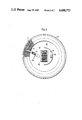
- FIG. 2 is a diagrammatic view along the horizontal sectional plane II--II of FIG. 1.
- FIG. 1 illustrates a portion of a metallurgical converter 10 comprising a metal wall 12 which is substantially cylindrical, at least in its central portion, and an inner refractory lining 14 comprised of a stack of refractory bricks laid on top of one another. It will be appreciated that this lining 14 has to be repaired regularly (on average approximately once every two weeks or three weeks).
- the present invention includes a platform 16 which, in the illustrated example, is suspended, by means of cables 18, from a winch or travelling bridge (not shown) which is located outside converter 10 such that platform 16 can be retained or lowered within converter 10.
- a winch or travelling bridge (not shown) which is located outside converter 10 such that platform 16 can be retained or lowered within converter 10.
- other means of moving platform 16 may be provided; for example telescopic arms, a crane, a cage with several elements, etc.
- the operational center may be secured to the end of a cage of variable length; or to a telescopic mast resting on the bottom of the vessel; or on the ground if there is an orifice in the bottom.
- Platform 16 comprises an upper table 20 and a lower table 22, between which is located a rotary cage 24 which can rotate about the axis O (in relation to stationary tables 20 and 22).
- the rotary connection between cage 24 and each of tables 20 and 22, is effected by means of an upper annular runway block 26 and a lower annular runway block 28.
- An electric motor 30, for example a stepping motor, mounted on cage 24 actuates a pinion 32 which engages with a toothed ring provided on the portion of runway block 26 which is integral with table 22. Consequently, during operation, motor 30 urges cage 24 to rotate about the axis O.
- a pinion 33 connected rigidly to pinion 32 engages with a toothed ring provided on the portion of the runway block 26 which is integral with table 20.
- table 22 is equipped with several extendable props 34, for example pneumatic jacks which are adapted to bear on the refractory lining 14 which was previously laid.
- the surface area of lower table 22 is preferably variable, so that the apparatus can be adapted for use in converters of variable or different diameters.
- table 22 can have a peripheral girdle 36 consisting of several radially displaceable or removable sections.
- girdle 36 must be sufficiently stable to be capable of supporting at least one person needed for directing the operations.
- the upper table is preferably also provided with a similar girdle 38 which functions as a protective shield for the person standing on the lower girdle.
- robot 40 mounted on rotary cage 24 and fastened either to the ceiling or to the floor of the latter.
- robot 40 is fastened to the ceiling of cage 24 and has four degrees of freedom symbolized by the arrows A, B, C, and D.
- Robot 40 comprises a bracket consisting of a first arm 42 which can slide vertically on a column 43 according to the arrow A and rotate horizontally about column 43 according to the arrow B, and a second arm 44 which is mounted at the end of the first arm 42 which can rotate relative to the latter about a vertical axis in the direction of arrow C.
- a gripping device 46 Located at the free end of the second arm 44 is a gripping device 46 which can also rotate about a vertical axis in the direction of the arrow D.
- Gripping device 46 can be designed in the form of a suction cup which can grasp and carry the bricks by means of pneumatic suction.
- Gripping device 46 can also be configured in the form of a tool with claws for picking up the bricks on their sides.
- the rotary movement B can also be replaced by a rectilinear movement. It will be appreciated that the vertical movement A may also be executed at the end of arm 44.
- Robot 40 is also provided, in a well known manner, with sensors (not shown) which make it possible to detect the position of the gripping device 46 and monitor and control its actions. It is also equiped with data-processing means necessary for completely automatic, independent and preprogrammed operation. As mentioned, such sensors and data processing means are all well known to those skilled in the art and so no further description thereof is necessary.
- platform 16 When lining a converter with bricks, platform 16 is lowered into converter 10 by unwinding the carrying cables 18. This lowering operation can be controlled and monitored for example, by a person standing on lower table 22.
- one or more pallets of bricks 48 and 50 are lowered by means of a winch through an orifice, provided for this purpose in the upper table 20, as far as the floor of the moveable cage 24.
- the operation is usually conducted with two pallets loaded with bricks of different conicities, so that brick-lining can be carried out according to the actual shape of the body of the vessel.
- robot 40 As a result of its degree of freedom, is moved continuously between a brick pick-up position corresponding substantially to the position of FIG. 1 and a position corresponding to that of FIG. 2, in which the bricks are laid on the lining 14.
- the bricks can be picked up and laid either individually or several may be picked up and laid at the same time.
- robot 40 Since robot 40 operates fully automatically, the person (i.e., operator) who is on the platform will have very little manual work to perform. The operator's main job will be to observe and check the quality of the bricks; control the vertical movement of the platform 16; and, if appropriate, lay the last brick of a row.
- motor 30 is controlled automatically by robot 40 in order to rotate the moveable cage 24.
- each robot can work independently, or in series so as to complement one another; in which case each robot carries out some of the work of the single robot illustrated in the Figures.
- the robots normally work fully automatically according to a predetermined program.
- the robots are preferably designed in such a way that, if required, they can be controlled manually and individually from a control panel.
- the robot 40 illustrated in the Figures is only an exemplary embodiment.
- a carriage which is displaceable in the radial direction.
- the pivoting arm 44 would then be mounted on this carriage by means of a pivot with a vertical axis of rotation.
- the gripping device 46 mounted on the end of arm 44 would then have to allow the gripping tool to rotate about a vertical axis with this tool moving vertically along this axis.
Landscapes
- Engineering & Computer Science (AREA)
- Chemical & Material Sciences (AREA)
- Manufacturing & Machinery (AREA)
- Materials Engineering (AREA)
- Metallurgy (AREA)
- Organic Chemistry (AREA)
- Mechanical Engineering (AREA)
- General Engineering & Computer Science (AREA)
- Furnace Housings, Linings, Walls, And Ceilings (AREA)
- Carbon Steel Or Casting Steel Manufacturing (AREA)
Applications Claiming Priority (2)
| Application Number | Priority Date | Filing Date | Title |
|---|---|---|---|
| LU85836A LU85836A1 (fr) | 1985-04-03 | 1985-04-03 | Installation pour la pose d'un garnissage refractaire sur la paroi interieure d'une enceinte |
| LU85836 | 1985-04-03 |
Publications (1)
| Publication Number | Publication Date |
|---|---|
| US4688773A true US4688773A (en) | 1987-08-25 |
Family
ID=19730434
Family Applications (1)
| Application Number | Title | Priority Date | Filing Date |
|---|---|---|---|
| US06/847,954 Expired - Fee Related US4688773A (en) | 1985-04-03 | 1986-04-03 | Apparatus for laying a refractory lining on the inner wall of a vessel |
Country Status (6)
| Country | Link |
|---|---|
| US (1) | US4688773A (de) |
| EP (1) | EP0198267B1 (de) |
| JP (1) | JPH0718657B2 (de) |
| AT (1) | ATE40412T1 (de) |
| DE (1) | DE3661935D1 (de) |
| LU (1) | LU85836A1 (de) |
Cited By (13)
| Publication number | Priority date | Publication date | Assignee | Title |
|---|---|---|---|---|
| US4765789A (en) * | 1986-04-01 | 1988-08-23 | Paul Wurth S.A | Apparatus for lining the inner wall of a vessel with bricks |
| US4786227A (en) * | 1986-06-05 | 1988-11-22 | Paul Wurth, S.A. | Automated apparatus for lining the inside wall of a vessel with bricks |
| US4827689A (en) * | 1986-01-28 | 1989-05-09 | Paul Wurth S.A. | Automated apparatus for lining the wall of a vessel with bricks |
| US5018923A (en) * | 1988-11-09 | 1991-05-28 | Paul Wurth S.A. | Automated bricklaying apparatus |
| ES2069480A2 (es) * | 1992-07-07 | 1995-05-01 | Wurth Paul Sa | Instalacion automatizada para revestir una pared interna de un recinto con mamposteria. |
| US20040116638A1 (en) * | 2001-02-28 | 2004-06-17 | Yoichi Ozawa | Continuous process for the production of conjugated diene polymers having narrow molecular weight distribution and products therefrom |
| US20050263945A1 (en) * | 2002-05-24 | 2005-12-01 | Speciality Minerals (Michigan) Inc. | Method for repairing a protective lining of an industrial reaction or transport vessel |
| DE102010063829A1 (de) | 2010-07-28 | 2012-02-02 | Sms Siemag Ag | Arbeitsbühne und deren Verwendung |
| US8965571B2 (en) | 2010-08-12 | 2015-02-24 | Construction Robotics, Llc | Brick laying system |
| US20150298948A1 (en) * | 2014-04-21 | 2015-10-22 | Randy Jackson | Method and apparatus for maintaining the interior of a vertical structure |
| WO2016126634A1 (en) * | 2015-02-03 | 2016-08-11 | Fosbel, Inc. | Methods and apparatus for constructing glass furnace structures |
| CN112985071A (zh) * | 2021-03-11 | 2021-06-18 | 山东九龙新材料有限公司 | 一种钢铁冶炼用铝碳化硅碳质耐火材料 |
| US20240417985A1 (en) * | 2023-06-19 | 2024-12-19 | Obshchestvo s ogranichennoi otvetstvennostiu «Diginavis» | Device and method for erecting structures using building blocks |
Citations (5)
| Publication number | Priority date | Publication date | Assignee | Title |
|---|---|---|---|---|
| SU197641A1 (ru) * | Государственный институт проектированию металлургических | Устройство для ремонта конвертеров:^иблио"и;^м.а | ||
| DE1154131B (de) * | 1961-05-20 | 1963-09-12 | Hwm Weh Maschf Hermann | Vorrichtung zum Herstellen einer aus Formbloecken bestehenden Auskleidung von Behaeltern, insbesondere Konvertern, die Metallschmelzen aufnehmen |
| SU403746A1 (ru) * | 1966-04-26 | 1973-10-26 | Государственный Союзный институт проектированию металлургических заводов | |ВСЕСОЮЗНАЯ403746М. Кл! С 21с 5/44УДК 669.184(088.8) |
| US4061319A (en) * | 1975-08-29 | 1977-12-06 | United States Steel Corporation | Mobile truck for relining a converter |
| US4303363A (en) * | 1977-10-31 | 1981-12-01 | Cervinter Ab | Work facilitating apparatus for conveying building material from a higher to a lower level |
Family Cites Families (7)
| Publication number | Priority date | Publication date | Assignee | Title |
|---|---|---|---|---|
| US3168163A (en) * | 1962-10-15 | 1965-02-02 | Clyde W Prosser | Portable scaffolds |
| US3927502A (en) * | 1972-05-15 | 1975-12-23 | United States Steel Corp | Method of lining a furnace |
| US3757484A (en) * | 1972-05-15 | 1973-09-11 | Combustion Enginc | Automated bricklaying device |
| JPS52165117U (de) * | 1976-06-08 | 1977-12-14 | ||
| JPS52165118U (de) * | 1976-06-08 | 1977-12-14 | ||
| FR2385863A1 (fr) * | 1977-03-28 | 1978-10-27 | Dietrich & Cie De | Plate-forme de travail de chariot de maconnage, notamment de convertisseur |
| FR2550984B1 (fr) * | 1983-07-07 | 1986-06-06 | Inst Rech Const Navale | Installation flexible de couples robot-porteurs |
-
1985
- 1985-04-03 LU LU85836A patent/LU85836A1/fr unknown
-
1986
- 1986-03-21 DE DE8686103876T patent/DE3661935D1/de not_active Expired
- 1986-03-21 AT AT86103876T patent/ATE40412T1/de not_active IP Right Cessation
- 1986-03-21 EP EP86103876A patent/EP0198267B1/de not_active Expired
- 1986-04-02 JP JP61076445A patent/JPH0718657B2/ja not_active Expired - Lifetime
- 1986-04-03 US US06/847,954 patent/US4688773A/en not_active Expired - Fee Related
Patent Citations (5)
| Publication number | Priority date | Publication date | Assignee | Title |
|---|---|---|---|---|
| SU197641A1 (ru) * | Государственный институт проектированию металлургических | Устройство для ремонта конвертеров:^иблио"и;^м.а | ||
| DE1154131B (de) * | 1961-05-20 | 1963-09-12 | Hwm Weh Maschf Hermann | Vorrichtung zum Herstellen einer aus Formbloecken bestehenden Auskleidung von Behaeltern, insbesondere Konvertern, die Metallschmelzen aufnehmen |
| SU403746A1 (ru) * | 1966-04-26 | 1973-10-26 | Государственный Союзный институт проектированию металлургических заводов | |ВСЕСОЮЗНАЯ403746М. Кл! С 21с 5/44УДК 669.184(088.8) |
| US4061319A (en) * | 1975-08-29 | 1977-12-06 | United States Steel Corporation | Mobile truck for relining a converter |
| US4303363A (en) * | 1977-10-31 | 1981-12-01 | Cervinter Ab | Work facilitating apparatus for conveying building material from a higher to a lower level |
Non-Patent Citations (2)
| Title |
|---|
| Benoit et al, Les Robots Strategie Industrielle, 12/82, pp. 8, 9 and 22. * |
| Tver et al, Robotics Sourcebook and Dictionary, 12/83, pp. v, 114 and 115. * |
Cited By (20)
| Publication number | Priority date | Publication date | Assignee | Title |
|---|---|---|---|---|
| US4827689A (en) * | 1986-01-28 | 1989-05-09 | Paul Wurth S.A. | Automated apparatus for lining the wall of a vessel with bricks |
| US4765789A (en) * | 1986-04-01 | 1988-08-23 | Paul Wurth S.A | Apparatus for lining the inner wall of a vessel with bricks |
| US4786227A (en) * | 1986-06-05 | 1988-11-22 | Paul Wurth, S.A. | Automated apparatus for lining the inside wall of a vessel with bricks |
| US5018923A (en) * | 1988-11-09 | 1991-05-28 | Paul Wurth S.A. | Automated bricklaying apparatus |
| ES2069480A2 (es) * | 1992-07-07 | 1995-05-01 | Wurth Paul Sa | Instalacion automatizada para revestir una pared interna de un recinto con mamposteria. |
| US5419669A (en) * | 1992-07-07 | 1995-05-30 | Paul Wurth S.A. | Installation for lining an internal wall of an enclosure with brickwork |
| US20040116638A1 (en) * | 2001-02-28 | 2004-06-17 | Yoichi Ozawa | Continuous process for the production of conjugated diene polymers having narrow molecular weight distribution and products therefrom |
| US20050263945A1 (en) * | 2002-05-24 | 2005-12-01 | Speciality Minerals (Michigan) Inc. | Method for repairing a protective lining of an industrial reaction or transport vessel |
| US8083982B2 (en) * | 2002-05-24 | 2011-12-27 | Specialty Minerals (Michigan) Inc. | Method for repairing a protective lining of an industrial reaction or transport vessel |
| WO2012013413A1 (de) | 2010-07-28 | 2012-02-02 | Sms Siemag Ag | Arbeitsbühne und deren verwendung |
| DE102010063829A1 (de) | 2010-07-28 | 2012-02-02 | Sms Siemag Ag | Arbeitsbühne und deren Verwendung |
| RU2561547C2 (ru) * | 2010-07-28 | 2015-08-27 | Смс Зимаг Аг | Рабочая площадка и ее применение |
| US8965571B2 (en) | 2010-08-12 | 2015-02-24 | Construction Robotics, Llc | Brick laying system |
| US20150298948A1 (en) * | 2014-04-21 | 2015-10-22 | Randy Jackson | Method and apparatus for maintaining the interior of a vertical structure |
| US10233065B2 (en) * | 2014-04-21 | 2019-03-19 | Randy Jackson | Method and apparatus for maintaining the interior of a vertical structure |
| WO2016126634A1 (en) * | 2015-02-03 | 2016-08-11 | Fosbel, Inc. | Methods and apparatus for constructing glass furnace structures |
| US10294085B2 (en) | 2015-02-03 | 2019-05-21 | Fosbel, Inc. | Methods and apparatus for constructing glass furnace structures |
| CN112985071A (zh) * | 2021-03-11 | 2021-06-18 | 山东九龙新材料有限公司 | 一种钢铁冶炼用铝碳化硅碳质耐火材料 |
| CN112985071B (zh) * | 2021-03-11 | 2023-03-14 | 山东九龙新材料有限公司 | 一种钢铁冶炼用铝碳化硅碳质耐火材料 |
| US20240417985A1 (en) * | 2023-06-19 | 2024-12-19 | Obshchestvo s ogranichennoi otvetstvennostiu «Diginavis» | Device and method for erecting structures using building blocks |
Also Published As
| Publication number | Publication date |
|---|---|
| EP0198267B1 (de) | 1989-01-25 |
| DE3661935D1 (en) | 1989-03-02 |
| JPH0718657B2 (ja) | 1995-03-06 |
| LU85836A1 (fr) | 1986-11-05 |
| EP0198267A1 (de) | 1986-10-22 |
| JPS61280386A (ja) | 1986-12-10 |
| ATE40412T1 (de) | 1989-02-15 |
Similar Documents
| Publication | Publication Date | Title |
|---|---|---|
| US5419669A (en) | Installation for lining an internal wall of an enclosure with brickwork | |
| US4688773A (en) | Apparatus for laying a refractory lining on the inner wall of a vessel | |
| US5018923A (en) | Automated bricklaying apparatus | |
| US4708562A (en) | Apparatus for lining the inner wall of a vessel with bricks | |
| JP2584231B2 (ja) | 容器の内壁を煉瓦で内張りする為の自動装置 | |
| US4787796A (en) | Apparatus for lining the inner wall of a vessel with bricks | |
| US3285390A (en) | Apparatus for lining metallurgical vessels, such as converters | |
| JPH0891770A (ja) | 長尺材吊上げ装置 | |
| JPH10204518A (ja) | 転炉炉内の煉瓦配設装置 | |
| CN116040459A (zh) | 一种降低吊具摇摆周期提高吊运精准度的方法及装置 | |
| JPH0554490U (ja) | 配管等の高所支持装置 | |
| JP3187141B2 (ja) | 高所作業台車装置 | |
| JP4041244B2 (ja) | 高炉煉瓦積み装置 | |
| JP4518982B2 (ja) | 転炉用レンガ配設装置及び方法 | |
| JPH0542543B2 (de) | ||
| JPH10218359A (ja) | 物品搬送装置及び物品搬送設備 | |
| JP2501999Y2 (ja) | レンガ積機用レンガ搬送装置 | |
| JPH089151Y2 (ja) | レンガ積装置 | |
| JP2564945B2 (ja) | 鉄塔自動組立方法及びそのための自動組立システム | |
| JP2645783B2 (ja) | タワー設備の作業デッキの組み立て構造 | |
| JPH0421712A (ja) | 転炉炉修装置 | |
| JPH0632996U (ja) | タワー設備のタワー昇降機構の取り付け構造 | |
| JPS61149420A (ja) | 転炉炉底耐火物築造装置 | |
| SE190049C1 (de) | ||
| JPH08209937A (ja) | 生コンクリートの移送装置 |
Legal Events
| Date | Code | Title | Description |
|---|---|---|---|
| AS | Assignment |
Owner name: PAUL WURTH S.A., 32 RUE D'ALSACE, L-1122 LUXEMBOUR Free format text: ASSIGNMENT OF ASSIGNORS INTEREST.;ASSIGNORS:LEGILLE, EDOUARD;MELAN, CORNEILLE;REEL/FRAME:004583/0203 Effective date: 19860630 Owner name: PAUL WURTH S.A.,LUXEMBOURG Free format text: ASSIGNMENT OF ASSIGNORS INTEREST;ASSIGNORS:LEGILLE, EDOUARD;MELAN, CORNEILLE;REEL/FRAME:004583/0203 Effective date: 19860630 |
|
| FEPP | Fee payment procedure |
Free format text: PAYOR NUMBER ASSIGNED (ORIGINAL EVENT CODE: ASPN); ENTITY STATUS OF PATENT OWNER: LARGE ENTITY |
|
| FPAY | Fee payment |
Year of fee payment: 4 |
|
| FPAY | Fee payment |
Year of fee payment: 8 |
|
| REMI | Maintenance fee reminder mailed | ||
| LAPS | Lapse for failure to pay maintenance fees | ||
| FP | Lapsed due to failure to pay maintenance fee |
Effective date: 19990825 |
|
| STCH | Information on status: patent discontinuation |
Free format text: PATENT EXPIRED DUE TO NONPAYMENT OF MAINTENANCE FEES UNDER 37 CFR 1.362 |