US4582446A - Connecting fitting for releasably connecting two platelike furniture members - Google Patents
Connecting fitting for releasably connecting two platelike furniture members Download PDFInfo
- Publication number
- US4582446A US4582446A US06/386,571 US38657182A US4582446A US 4582446 A US4582446 A US 4582446A US 38657182 A US38657182 A US 38657182A US 4582446 A US4582446 A US 4582446A
- Authority
- US
- United States
- Prior art keywords
- housing
- rotary wedge
- wedge
- fitting according
- connecting fitting
- Prior art date
- Legal status (The legal status is an assumption and is not a legal conclusion. Google has not performed a legal analysis and makes no representation as to the accuracy of the status listed.)
- Expired - Fee Related
Links
- 230000037431 insertion Effects 0.000 claims abstract description 8
- 238000003780 insertion Methods 0.000 claims abstract description 8
- 230000013011 mating Effects 0.000 claims description 8
- 230000002093 peripheral effect Effects 0.000 claims description 5
- 239000002184 metal Substances 0.000 claims description 3
- 230000006835 compression Effects 0.000 claims description 2
- 238000007906 compression Methods 0.000 claims description 2
- 230000000694 effects Effects 0.000 claims description 2
- CNQCVBJFEGMYDW-UHFFFAOYSA-N lawrencium atom Chemical compound [Lr] CNQCVBJFEGMYDW-UHFFFAOYSA-N 0.000 description 10
- ORQBXQOJMQIAOY-UHFFFAOYSA-N nobelium Chemical compound [No] ORQBXQOJMQIAOY-UHFFFAOYSA-N 0.000 description 7
- 238000006073 displacement reaction Methods 0.000 description 5
- 238000005452 bending Methods 0.000 description 1
- 230000001419 dependent effect Effects 0.000 description 1
- 238000007373 indentation Methods 0.000 description 1
- 239000000463 material Substances 0.000 description 1
- 230000000717 retained effect Effects 0.000 description 1
Images


Classifications
-
- F—MECHANICAL ENGINEERING; LIGHTING; HEATING; WEAPONS; BLASTING
- F16—ENGINEERING ELEMENTS AND UNITS; GENERAL MEASURES FOR PRODUCING AND MAINTAINING EFFECTIVE FUNCTIONING OF MACHINES OR INSTALLATIONS; THERMAL INSULATION IN GENERAL
- F16B—DEVICES FOR FASTENING OR SECURING CONSTRUCTIONAL ELEMENTS OR MACHINE PARTS TOGETHER, e.g. NAILS, BOLTS, CIRCLIPS, CLAMPS, CLIPS OR WEDGES; JOINTS OR JOINTING
- F16B12/00—Jointing of furniture or the like, e.g. hidden from exterior
- F16B12/10—Jointing of furniture or the like, e.g. hidden from exterior using pegs, bolts, tenons, clamps, clips, or the like
- F16B12/12—Jointing of furniture or the like, e.g. hidden from exterior using pegs, bolts, tenons, clamps, clips, or the like for non-metal furniture parts, e.g. made of wood, of plastics
- F16B12/20—Jointing of furniture or the like, e.g. hidden from exterior using pegs, bolts, tenons, clamps, clips, or the like for non-metal furniture parts, e.g. made of wood, of plastics using clamps, clips, wedges, sliding bolts, or the like
- F16B12/2009—Jointing of furniture or the like, e.g. hidden from exterior using pegs, bolts, tenons, clamps, clips, or the like for non-metal furniture parts, e.g. made of wood, of plastics using clamps, clips, wedges, sliding bolts, or the like actuated by rotary motion
- F16B12/2027—Jointing of furniture or the like, e.g. hidden from exterior using pegs, bolts, tenons, clamps, clips, or the like for non-metal furniture parts, e.g. made of wood, of plastics using clamps, clips, wedges, sliding bolts, or the like actuated by rotary motion with rotating excenters or wedges
-
- F—MECHANICAL ENGINEERING; LIGHTING; HEATING; WEAPONS; BLASTING
- F16—ENGINEERING ELEMENTS AND UNITS; GENERAL MEASURES FOR PRODUCING AND MAINTAINING EFFECTIVE FUNCTIONING OF MACHINES OR INSTALLATIONS; THERMAL INSULATION IN GENERAL
- F16B—DEVICES FOR FASTENING OR SECURING CONSTRUCTIONAL ELEMENTS OR MACHINE PARTS TOGETHER, e.g. NAILS, BOLTS, CIRCLIPS, CLAMPS, CLIPS OR WEDGES; JOINTS OR JOINTING
- F16B12/00—Jointing of furniture or the like, e.g. hidden from exterior
- F16B12/10—Jointing of furniture or the like, e.g. hidden from exterior using pegs, bolts, tenons, clamps, clips, or the like
- F16B12/12—Jointing of furniture or the like, e.g. hidden from exterior using pegs, bolts, tenons, clamps, clips, or the like for non-metal furniture parts, e.g. made of wood, of plastics
- F16B12/20—Jointing of furniture or the like, e.g. hidden from exterior using pegs, bolts, tenons, clamps, clips, or the like for non-metal furniture parts, e.g. made of wood, of plastics using clamps, clips, wedges, sliding bolts, or the like
- F16B12/2009—Jointing of furniture or the like, e.g. hidden from exterior using pegs, bolts, tenons, clamps, clips, or the like for non-metal furniture parts, e.g. made of wood, of plastics using clamps, clips, wedges, sliding bolts, or the like actuated by rotary motion
- F16B12/2027—Jointing of furniture or the like, e.g. hidden from exterior using pegs, bolts, tenons, clamps, clips, or the like for non-metal furniture parts, e.g. made of wood, of plastics using clamps, clips, wedges, sliding bolts, or the like actuated by rotary motion with rotating excenters or wedges
- F16B12/2036—Jointing of furniture or the like, e.g. hidden from exterior using pegs, bolts, tenons, clamps, clips, or the like for non-metal furniture parts, e.g. made of wood, of plastics using clamps, clips, wedges, sliding bolts, or the like actuated by rotary motion with rotating excenters or wedges with rotating excenters or wedges acting on a head of a pin or screw
-
- F—MECHANICAL ENGINEERING; LIGHTING; HEATING; WEAPONS; BLASTING
- F16—ENGINEERING ELEMENTS AND UNITS; GENERAL MEASURES FOR PRODUCING AND MAINTAINING EFFECTIVE FUNCTIONING OF MACHINES OR INSTALLATIONS; THERMAL INSULATION IN GENERAL
- F16B—DEVICES FOR FASTENING OR SECURING CONSTRUCTIONAL ELEMENTS OR MACHINE PARTS TOGETHER, e.g. NAILS, BOLTS, CIRCLIPS, CLAMPS, CLIPS OR WEDGES; JOINTS OR JOINTING
- F16B12/00—Jointing of furniture or the like, e.g. hidden from exterior
- F16B12/10—Jointing of furniture or the like, e.g. hidden from exterior using pegs, bolts, tenons, clamps, clips, or the like
- F16B2012/106—Connection bolts for connection fittings
-
- Y—GENERAL TAGGING OF NEW TECHNOLOGICAL DEVELOPMENTS; GENERAL TAGGING OF CROSS-SECTIONAL TECHNOLOGIES SPANNING OVER SEVERAL SECTIONS OF THE IPC; TECHNICAL SUBJECTS COVERED BY FORMER USPC CROSS-REFERENCE ART COLLECTIONS [XRACs] AND DIGESTS
- Y10—TECHNICAL SUBJECTS COVERED BY FORMER USPC
- Y10S—TECHNICAL SUBJECTS COVERED BY FORMER USPC CROSS-REFERENCE ART COLLECTIONS [XRACs] AND DIGESTS
- Y10S403/00—Joints and connections
- Y10S403/12—Furniture type having a rotatable fastener or fastening element that tightens connection
-
- Y—GENERAL TAGGING OF NEW TECHNOLOGICAL DEVELOPMENTS; GENERAL TAGGING OF CROSS-SECTIONAL TECHNOLOGIES SPANNING OVER SEVERAL SECTIONS OF THE IPC; TECHNICAL SUBJECTS COVERED BY FORMER USPC CROSS-REFERENCE ART COLLECTIONS [XRACs] AND DIGESTS
- Y10—TECHNICAL SUBJECTS COVERED BY FORMER USPC
- Y10T—TECHNICAL SUBJECTS COVERED BY FORMER US CLASSIFICATION
- Y10T403/00—Joints and connections
- Y10T403/59—Manually releaseable latch type
- Y10T403/591—Manually releaseable latch type having operating mechanism
- Y10T403/595—Lever
Definitions
- This invention relates to a connecting fitting for releasably connecting two platelike furniture members, which preferably extend at right angles to each other, comprising two fitting elements which are adapted to be secured to respective ones of the furniture members to be connected, wherein one of said fitting elements has a locking projection and is adapted to be slidably inserted into a receiving opening of the other fitting element until the fitting elements and/or furniture members engage each other, and the other fitting element is provided with a hook-shaped rotary wedge for interengaging with the projection so as to lock the fitting elements to each other.
- Connecting fittings comprising a rotatably mounted rotary wedge, which can be rotated by means of a screwdriver or the like in order to interconnect the fitting elements, are known, e.g., from Laid-open German Application Nos. 29 09 656, 29 08 475, 25 41 554, 28 36 678 and 27 48 272.
- the known connecting fittings have the disadvantage that they can be mounted only with difficulty and a screw driver or another tool for interconnecting the fitting elements and, if desired, for forcing them against each other, is always required in order to assemble the fitting elements.
- Laid-open German Application No. 22 06 684 discloses a connecting fitting which comprises a wedge or rotary wedge, which is spring-loaded and to tighten the assembly is forced behind the enlarged head of the pin-shaped second fitting element.
- the wedge or rotary wedge assumes a position which said wedge is pushed back from the receiving opening and is retained by a stop formed by a step of the housing.
- the wedge or rotary wedge has a web, which in this positon lies in the receiving opening and which is engaged by the head of the pin as the latter is inserted so that the wedge or rotary wedge is then pushed away from its stop and is thus released.
- That known connecting fitting has a complicated structure and has the disadvantage that it can be disassembled only with difficulty if a piece of furniture is to be disassembled.
- this object is accomplished in that the rotary wedge is rotatably mounted in a wedge housing and is biased in a locking sense by a torsion spring, and that unlocking means are provided to rotate the rotary wedge in a retracting sense as well as resilient means for locking the rotary wedge in its retracted position, which resilient means are arranged to release the rotary wedge in response to the insertion of the projection of the other fitting element.
- the connecting fitting according to the invention can be assembled in a simple manner and without a tool in that the rotary wedge is held in its retracted position while the fitting elements are assembled and is subsequently released so that the spring urges the rotary wedge to its locking position in which the rotary wedge connects the fitting elements and forces them against each other by its wedge action.
- the unlocking means for retracting the rotary wedge consist suitably of a lever, which is secured to the pin and extends at right angles thereto and lies on the upper surface of the top wall of the wedge housing.
- a disc provided with a handle lever is pivoted in the top wall of the wedge housing and is centered on the axis of the pin and has a sector-shaped recess, which extends over the lever, which is secured to the pin.
- the angle included by the sector is approximately as large as the angle through which the short lever secured to the pin is moved when the rotary wedge springs from its rectracted position to its locking position.
- Said locking means suitably comprise a leaf spring, which is secured at one end to the rotary wedge and at its other end has a hook-shaped portion, which in the retracted position of the rotary wedge snaps behind a protruding portion of the housing.
- the hook-shaped portion may be provided with an outwardly extending tag, which extends in the opening that is formed in the other fitting element and adapted to expose the projection so that the hook-shaped portion will be disengaged from the housing as the other fitting element is inserted and engages said tag.
- the disc provided with the handle lever is provided with a beveled edge and is rotatably mounted in a mating undercut groove formed in the top wall of the wedge housing, the handle lever connected to the disc extends in a sector-shaped recess formed in the top surface of the wedge housing, and the handle lever is formed at one end with a recess, which in the retracted position of the rotary wedge receives a projecting cam that is provided at the peripheral edge of the sector-shaped recess.
- the handle lever can be caused to interlock with the cam so that the fitting elements can then be pulled apart in a simple manner.
- the rotary wedge When it is desired to interconnect the fitting elements, the rotary wedge and is held in its retracted position by the locking means which are disposed in the path along which the other fitting element is slidably inserted. As a result, the rotary wedge will spring to its locking position when the other fitting element has been slidably inserted, provided that the handle lever connected to the disc has been swung back before so that it will not obstruct the movement of the rotary wedge to its locking position.
- the furniture member which is to be carried by another should not only be forced with its end face against the carrying furniture member but should be secured to the latter so as to prevent a displacement of the carried furniture member transversely to its own plane or in the plane of the carrying furniture member. That displacement is usually prevented in that the furniture members to be connected are provided with interengaging steps or with pins which extend into mating openings in the other member. But these special supporting means required in addition to the tightening rotary wedge joint involve an additional expenditure, which adds to the cost of the connecting fittings.
- a further preferred feature of the invention resides in that that fitting element which has an interengageable projection consists of a pin, which has an enlarged head, and the rotary wedge consists of two discs, which extend in spaced apart, parallel planes and are provided with prings, which are curved along arcs of a circle and straddle the shank of the pin behind the head and are supported on and forced against the rear face of the head.
- the furniture members to be connected are forced against each other and the rotary wedge will straddle the headed shank of the fitting element so that the carried furniture member will be secured to the carrying furniture member in such a manner that a displacement which is transverse to the planes of the discs of the rotary wedge will be prevented.
- the fitting element consisting of a pin having an enlarged head can be secured in a particularly simple manner and may simply be screwed into the furniture member if the pin is provided with screw threads.
- the step which is formed on the pin between the head and the shank is suitably conical or convex so that the head can be engaged on its rear side with low friction by the pronglike rotary wedges, which are curved approximately along an arc or a circle.
- the discs of the rotary wedge have circular edges and the rotary wedge is rotatably mounted in that said circular edges are guided in annular grooves of the pot-shaped housing which accommodates said discs.
- the rotary wedge consists of two spaced apart discs, it can present an adequate resistance also to canting forces.
- the rotary wedge is suitably a channel-shaped member made from a sheet metal stamping and the web which connects the discs of the rotary wedge suitably lies within the circular periphery so that the web will not obstruct the insertion of the edges of the rotary wedge into the annular grooves.
- the torsion spring consists of a coiled spring having an axis which coincides with the axis of rotation of the rotary wedge, one end leg of the torsion spring is held in an aperture of the housing and the other end leg is held at the rotary wedge.
- one end of a leaf spring is secured in the housing and said leaf spring has a free portion, which is provided at its end with a hook and which is resilient in a plane that is parallel to the rotary wedge, the rotary wedge is provided with a pin or projection, which is adapted to interengage with the hook when the fitting element is in a ready position, in which the rotary wedge is retracted from the receiving opening, and an intermediate portion of the leaf spring is exposed in a sufficient length through the opening for receiving the head of the other fitting element so that the hook will release the pin or projection in response to the insertion of the head.
- the fitting elements can be assembled in a simple manner in that that furniture member to which the fitting element provided with the rotary wedge is secured is pushed onto the other fitting element consisting of the headed pin. The head will then disengage the hook from the rotary wedge so that the latter springs automatically to its locking position.
- An axial pin may be mounted in the top wall of the housing for the rotary wedge and said axial pin may carry the unlocking lever disposed on the top of the housing and may be provided at its lower end with a stop for cooperating with a stop of the rotary wedge in such a manner that the unlocking lever may be used to turn the rotary wedge to its retracted position, in which the fitting elements can be separated.
- the hooked leaf spring holds the rotary wedge in its retracted position so that the handle lever can then be rotated opposite to the unlocking sense whereas the rotary wedge will not spring to its locking position until the other fitting element has caused the hook to release the rotary wedge.
- the means for mounting the rotary wedge may consist of a pin, which extends through the torsion spring.
- the rotary wedge may additionally be supported at its circular edges on the cylindrical inside surface of the housing so that a higher resistance will be presented to canting forces.
- the wedge housing has substantially the shape of an entire cylinder and is received by a bore, which is entirely provided in the edge portion of the furniture member that is to be secured, and the headed pin extends into the receiving opening through a bore in the land between the bore and the end face of the furniture. That embodiment is particularly suitable for relatively thick furniture members.
- a disc is rotatably mounted in the wedge housing on a mounting pin, which is parallel to the center line of the wedge housing, and said disc has a cylindrical side wall, which increases in height in wedge shape and constitutes the rotary wedge, which extends into the opening that is intended to receive the headed pin, which opening is parallel to the mounting pin. That embodiment may be used, e.g., to connect bottom plates to the lower end faces of vertical furniture walls.
- the disc In order to hold the disc provided with the rotary wedge in its ready position when the fitting elements are to be assembled, the disc may have a sector-shaped portion which is not provided with said side wall and which receives a radially outwardly extending, hook-shaped end of a leaf spring, which at its end opposite to the hook is secured to the cylindrical side wall, the housing has an inside surface, which surrounds the disc and is formed laterally of the receiving opening with a step, which is engageable by the lever in the ready position, and the hook has a tag, which extends laterally to be exposed through the receiving opening.
- the head of said other fitting element As the other fitting element is slidably inserted into the receiving opening, the head of said other fitting element, which head has suitably a convex outside surface, will slide on said tag so as to disengage the hook from the disc and the rotary wedge will then spring to its locking position.
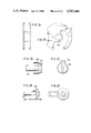
- FIG. 1 is a side elevation showing that fitting element which is provided with the rotary wedge and comprises a housing, which is divided in a vertical center plane and one half of which has been omitted in the drawing,
- FIG. 2 is a horizontal sectional view taken on line II--II in FIG. 1 and showing the two housing halves removed from each other,
- FIG. 3 is a side elevation showing the fitting element which is provided with an eye for the rotary wedge
- FIG. 4 is a side elevation showing the torsion spring by which the rotary wedge is loaded
- FIG. 5 is a top plan view showing the leaf spring for locking the rotary wedge in its retracted position
- FIG. 6 is a side elevation showing the leaf spring of FIG. 5,
- FIG. 7 is a horizontal sectional view showing the fitting elements with the rotary wedge in its retracted position
- FIG. 8 is a top plan view showing the fitting elements of FIG. 7 with the handle lever in position for the assembling of the fitting
- FIG. 9 is a horizontal sectional view which is similar to FIG. 7 and shows the fitting elements which have been pushed together and the rotary wedge in its retracted position
- FIG. 10 is a top plan view showing the fitting elements of FIG. 9,
- FIG. 11 is a horizontal sectional view which is similar to FIGS. 7 and 9 and shows the rotary wedge held in its retracted position by the locked handle lever,
- FIG. 12 is a top plan view showing the fitting elements in the position shown in FIG. 11,
- FIG. 13 is a top plan view showing the rotary wedge
- FIG. 14 is a bottom view showing the disc which is provided with the handle lever
- FIG. 15 is a side elevation showing the disc of FIG. 14,
- FIG. 16 is a front elevation showing the fitting element provided with the eye
- FIG. 17 is a side elevation showing the pivot pin carrying the rotary wedge
- FIG. 18 is a longitudinal sectional view taken on line I--I of FIG. 19 and showing a different embodiment of a wedge housing
- FIG. 19 is a horizontal sectional view taken on line II--II in FIG. 18 and showing the wedge housing
- FIG. 20 is a side elevation showing the fitting element which consists of a headed pin
- FIG. 21 is a top plan view showing the torsion spring
- FIG. 22 is a side elevation showing the handle lever and the cylindrical housing for the torsion spring
- FIG. 23 is a bottom view showing the handle lever of FIG. 22,
- FIG. 24 is a side elevation of a rotary wedge consisting of two discs
- FIG. 25 is a top plan view showing the rotary wedge of FIG. 24,
- FIG. 26 is a side elevation showing a handle lever for actuating the rotary wedge, a housing for the torsion spring, and a pivot pin for the rotary wedge,
- FIG. 27 is a top plan view showing the handle lever of FIG. 26,
- FIG. 28 is a side elevation showing a further embodiment of a housing for the torsion spring, the handle lever and the pivot pin for the rotary wedge,
- FIG. 29 is a bottom view showing the spring housing of FIG. 28,
- FIGS. 30 and 31 are, respectively, a horizontal sectional view and a top plan view showing that fitting element which is provided with the rotary wedge in ready position,
- FIGS. 32 and 33 are views which are similar to FIGS. 30 and 31 and show the connecting fitting after the headed pin has effected a release of the rotary wedge and the latter has sprung to its locking position
- FIGS. 34 and 35 are view which are similar to FIGS. 32 and 33 and show the connecting fitting with the handle lever locked in its retracted position so that the connecting fitting can be unlocked,
- FIG. 36 is a sectional view showing furniture members which are to be connected and comprise a vertical furniture wall having a through bore, into which two headed pins have been screwed from opposite sides, and horizontal furniture members to be connected to said pins by being displaced in their plane or transversely thereto,
- FIG. 37 is a sectional view showing two interconnected furniture members, one of which has a milled bore in which the fitting element provided with the rotary wedge is entirely accommodated,
- FIG. 38 is a top plan view showing the interconnected furniture members of FIG. 37.
- FIG. 39 is a sectional view taken on the parting plane of the wedge housing and showing two interconnected furniture members
- FIG. 40 is a horizontal sectional view taken on line XXIII--XXIII of FIG. 39 and showing the wedge housing
- FIG. 41 is a side elevation of the pivot pin for the rotary wedge and the handle lever
- FIG. 42 is a top plan view showing the handle lever of FIG. 41.
- FIG. 43 is a top plan view showing the leaf spring having an end hook
- FIG. 44 is a side elevation showing the leaf spring of FIG. 43.
- FIG. 45 is a side elevation showing the rotary wedge formed by a cylindrical wall
- FIG. 46 is a top plan view showing the rotary wedge of FIG. 45.
- FIG. 47 is a side elevation showing the torsion spring
- FIGS. 48 and 49 are, respectively, a horizontal sectional view and a top plan view showing the fitting element provided with the rotary wedge in its ready position
- FIGS. 50 and 51 are views corresponding to FIGS. 48 and 49 and show the fitting element in its locking position
- FIGS. 52 and 53 are views corresponding to FIGS. 50 and 51 and show the rotary wedge in its released position
- FIGS. 54 and 55 are, respectively, a top plan view and a side elevation of a wedge housing which has been fitted into a furniture member and has a wedge-shaped ramp for locking the handle lever,
- FIG. 56 is a side elevation showing the pivot pin for the rotary wedge and the handle lever
- FIG. 57 is a longitudinal sectional view taken on line A-B in FIG. 58 and showing another embodiment of a fitting element
- FIG. 58 is a transverse sectional view taken on line C-D in FIG. 57,
- FIG. 59 is a rear elevation showing the slider of FIGS. 57 and 58.
- FIG. 60 is a side elevation showing the slider of FIG. 59.
- the connecting fitting shown in the drawings consists of a fitting element 1, which is provided with an eye 3, and a fitting element 2, which comprises the rotary wedge 4.
- the fitting elements 1 and 2 are provided with pot-shaped housings.
- the fitting element 1 comprises two cheeks 5, 6, which are vertically spaced and vertically aligned and are interconnected by a pin 7, which defines the eye 3.
- the cheeks 5, 6 are anchored in the pot-shaped housing 8 in the manner which is apparent from FIG. 16.
- the pin 7 extends over a groove, which is formed in the housing 8. That groove has the shape of a segment of a circle. As a result, the movement of the rotary wedge 4 into the eye 3 defined by the pin 7 will not be obstructed.
- the housing 8 of the fitting element 1 is provided with a flange 11, which defines a step 10, which constitutes a stop for engaging the fitting element 2.
- the rotary wedge 4 is non-rotatably connected to the pin 12, which is rotatably mounted in the housing consisting of housing halves 13, 14.
- the housing 13, 14 has substantially the shape of a cylindrical disc and has a flat forward face 15.
- the pin 12 is mounted in the housing 13, 14 on an axis which is parallel to the longitudinal axis of the cylindrical housing.
- the flat forward surface 15 of the housing is formed with a slot.
- the rotary wedge 4 is mounted for rotation in a horizontal diametral plane and has a round wedge-shaped forward end portion 16, which is adapted to extend out through said slot.
- a coiled torsion spring 17 is fitted on the lower end of the pin 12 and has one end leg 18, which bears on an abutment surface of the housing, and an angled second end leg 19, which extends into a slot 20 formed in the disc-shaped rotary wedge 4 and is radially displaceable in said slot 20 during a rotation of the rotary wedge 4.
- the top end portion of the pin 12 extends through the top wall of the housing 13, 14 and carries a short lever arm 21, which lies on the upper surface of the housing. That lever arm 21 is covered by a rotary circular disc 22, which is formed on its underside with a sector-shaped recess 23, which accommodates the lever arm 21.
- the rotary disc 22 is provided at its lower edge with a beveled annular flange 24 and is rotatably mounted in that said flange is received in a mating undercut groove formed in the top surface of the housing.
- the rotary disc 22 is provided with a handle lever 25, which extends in a sector-shaped recess 26 in the top surface of the housing 13, 14.
- the sector angle of the recess 26 is at least as large as the sector angle of the recess 23.
- the rotary wedge 4 consists of a disc, which has a wedge-shaped portion 16, which is curved according to an arc of a circle.
- the recess which defines the inside surface of the wedge-shaped portion is continued by an indentation 26, in which the U-shaped rear end 27 of the leaf spring 28 is anchored.
- the leaf spring 28 has a straight portion, from which a hook 29 is angled, which is continued by a curved tag 30, which is enlarged in width and is forked, as is apparent from FIG. 6.
- the circular disc-shaped rotary wedge 4 has a central bore 31 and the pin 12 has a portion that is formed with scores 32 and non-rotatably connected to the rotary wedge 4 in the bore 31.
- the housing for the rotary wedge 4 is divided into the housing halves 13, 14 in an axial plane which bisects the flat forward surface 15.
- the housing 13, 14 has an approximately cylindrical cavity 33, which is open-bottomed and in which the pin 12 is approximately centrally mounted at one end in a web 34, which protrudes into the cavity, and at the other end in a bore formed in the top wall which defines the cavity.
- Respective halves of the bearing bores are formed in the housing halves 13, 14, so that the assembling is facilitated.
- the housing halves are provided with pins and mating recesses for connecting and centering the housing halves.
- the end leg 18 of the torsion spring 17 is held in a suitable blind hole 35 formed in the housing half 13.
- the surface defining the cylindrical cavity 33 is formed with a circular groove 36, into which the rotary wedge 4 extends.
- the wall which defines the cavity 33 Adjacent to the flat forward face 15, the wall which defines the cavity 33 is formed with approximately right-angled edges 37, 38, which are disposed on both sides of the groove 36 and define the receiving opening 39.
- the hook 29 of the leaf spring 28 is adapted to interengage with the edge 37 in the manner which is apparent from FIG. 7 so that the rotary wedge 4 can be locked in its retracted position. In that position the tag 30 of the leaf spring 28 lies in the opening 39 for receiving the fitting element 1 so that in response to the insertion of the fitting element 1 the rotary wedge 4 will be released and the hook 29 will then be freely slidable over the edge between the groove 36 and the surface which defines the cavity 33.
- the handle lever 25 has a recess 40, which is adapted to receive the camlike projection 41, which is provided on the peripheral surface that defines the sector-shaped recess 26.
- FIGS. 7 and 8 show the fitting elements in the position in which they are ready for being assembled.
- the rotary wedge 4 has been turned to its retracted position so that the hook 29 of the leaf spring 28 has snapped behind the projection 37 of the housing and holds the rotary wedge 4 in its retracted position, which is shown in FIG. 7.
- the handle lever 25 is then turned back to the position shown in FIG. 8.
- the fitting element 1 When the fitting element 1 is then inserted, it will engage the tag 30 of the leaf spring 28 and will thus effect a release of the rotary wedge 4 so that the latter can spring to its locking position, shown in FIG. 9.
- the lever 21 is free to move in the sector-shaped recess 23 of the rotary disc 22, the rotary wedge 4 will be free to move to its locking position.
- the tag 30 is forked, as is shown in FIG. 6, so that the rotary wedge extending through the tag 30 will not be restrained by the latter.
- the handle lever 25 When it is desired to separate the fitting elements, the handle lever 25 is moved to its retaining position in that the cam 41 falls into the aperture 40, as is apparent from FIG. 12.
- the tag 30 of the leaf spring 28 bears on the outside surface of the pin 7 so that the fitting elements can be pulled apart without an obstruction.
- the hook 29 of the leaf spring 28 again snaps in behind the projection 37 of the housing so that the rotary wedge is locked in its retracted position, as is shown in FIG. 7.
- the connecting fitting consists of the fitting element 102, which is provided with the rotary wedge, and the connecting fitting 103, which consists of a screw-threaded headed pin.
- the fitting element 102 comprises a substantially cylindrical housing, which is centrally divided into the housing halves 104, 105 and which has a flat forward face 106, which is symmetrical to the parting plane of the housing.
- the flat forward face 106 has a central opening 107 for receiving the fitting element 103.
- the receiving opening 107 leads into a substantially cylindrical cavity 108, which is formed in the housing 104, 105 and in which the rotary wedge 101 is rotatably mounted.
- the rotary wedge 101 has been made by bending from a sheet metal stamping and comprises two parallel circular discs 109, 110 and a web 111 connecting said discs.
- the discs 109, 110 have punched crescent-shaped recesses 112, which define prongs 113, which extend along respective arcs of a circle.
- the discs 109, 110 have circular edges 114, 115, which are guided in annular grooves 116, 117 formed in the surface that defines the cylindrical cavity 108 of the housing 104, 105.
- the web 11 extends in recesses 118 formed in the peripheries of the discs 109, 110 so that the web cannot obstruct the insertion of the edges 114, 115 into the annular grooves 116, 117.
- a coiled torsion spring 119 is mounted, which is centered on the axis of rotation of the rotary wedge 101 and is surrounded by a cylindrical housing 120, which constitutes a pivot pin.
- a handle lever 121 is connected to the top of the housing 120 and extends at right angles to the axis of the housing 120 in a sector-shaped recess 122 of the top of the housing 104, 105. This recess 122 is apparent from FIGS. 31, 33 and 35.
- the cylindrical housing 120 which contains the spring 119 is mounted in a mating cylindrical opening of the wedge housing 104, 105 and at its top edge has a frustoconical portion 123, which is embraced by the mating frustoconical inside surface of an edge portion 124 of the housing 104, 105 so that the spring housing 120 is rotatably and axially immovably mounted in the wedge housing 104, 105.
- the wall of the spring housing 120 has a part-sector-shaped aperture 125, through which the end legs of the torsion spring 119 extend.
- the torsion spring 119 has a radial or tangential upper end leg 126, which is held in a bore 127 of the housing half 105.
- the other end leg 128 of the torsion spring 119 is right-angled and extends through bores 129 in the discs 109, 110 of the rotary wedge 101.
- a leaf spring 131 has one end 130, which is held in a recess formed in the housing half 105, and a free end portion formed with a hook 132. That hook 132 is arranged to hook over the pinlike end leg 128 in the ready position shown in FIG. 19, in which the wedge-shaped prong 113 has been retracted from the receiving opening 107.
- the intermediate portion 133 of the leaf spring 131 is offset or arcuate to form a beveled run-up ramp 134, which protrudes into the receiving opening 107.
- the pin-shaped fitting element 103 comprises a shank 135, which carries an enlarged head 136, which has a slot for a screwedriver. At its lower end, the shank 135 is provided with a collar 136, which limits the depth to which the pin 103 can be screwed. On the side of the collar 136 which is opposite to the shank 135, the pin 103 comprises a screw portion 137, which is aligned with the shank 135 and formed with screw threads.
- the cylindrical spring housing 120 contains a central pin 138, which extends through the coiled portion of the torsion spring 119.
- That wall 140 of the cylindrical housing 120 which is disposed adjacent to the handle lever 121 has a vertical end face 139, the lower edge of which constitutes a stop for the angled spring leg 128, so that the rotary wedge 101 can be turned to its retracted position, shown in FIG. 19, by a turning of the handle lever 121.
- the rotary wedge is turned by the handle lever 121 to its retracted position, which is apparent from FIGS. 19 and 30 and in which the hook 132 of the leaf spring 131 interengages with the vertical end leg 128 of the torsion spring 119.
- the handle lever 121 is then turned to the position shown in FIG. 31 so that it will not obstruct a movement of the rotary wedge to its locking position.
- the head 136 is then inserted into the receiving opening 107 of the fitting element 102, the head will run up on the ramp portion 134 of the leaf spring 131 and will force back the latter until the hook 132 has been disengaged from the end leg 128.
- the rotary wedge 101 will then spring to its locked position, shown in FIG. 32. In that position, the head 136 bears on the apex of the curved portion of the leaf spring 131.
- the handle lever 121 When the fitting elements are then to be unlocked, the handle lever 121 is turned to the position shown in FIG. 35, in which the recess 141 in its end face snaps over the projection 142 provided on the surface which defines the sector-shaped recess 122. During the movement to that position the edge 139 of the inside surface 140 of the calindrical housing 120 has carried and angled end leg 128 along and has thus turned the rotary wedge 101 to its retracted position, shown in FIG. 34. When the fitting element 102 is then pulled from the fitting element 103, the head 136 releases the leaf spring 131 so that the hook 132 can again snap behind the end leg 128, which constitutes a locking pin. As the rotary wedge 101 is now locked in its retracted position, the handle lever 121 can be turned back from the position shown in FIG. 35 to that shown in FIG. 31.
- the rotary wedge shown in FIGS. 24 and 25 differs from the rotary wedge shown in FIGS. 18 and 19 only by the provision of the central bore 142, with which the rotary wedge is mounted on the extended central pin 143 of the calindrical housing 120 for the torsion spring.
- the rotary wedge is rotatably mounted on the pin 143, there is no need for guide grooves in the surfaces defining the calindrical cavity of the wedge housing so that the circular edges of the rotary wedge can bear directly on the surface which defines that cylindrical cavity.
- the lockable lever 144 for moving the rotary wedge to its retracted position is only short and the housing 120 can be rotated by means of a screwdriver inserted into a slot 145 in the top surface of the housing 120.
- the central pin is stepped and comprises a portion 146, which is larger in diameter and extends through the torsion spring, and a thinner portion 147, on which the rotary wedge is mounted.
- the wall of the housing 120 is provided on its outside edge with a tooth 148, which engages the bottom 149 of the recess 112 formed in the rotary wedge in order to carry the same along to its retracted position during a corresponding rotation of the handle lever.
- a sleeve 149 is inserted in a through bore of a vertical furniture wall and fitting elements 103 having standard, e.g., metric screw threads are screwed into said sleeve 149 from opposite ends thereof.
- the horizontal furniture members can be interlocked with the fitting elements 103 by a displacement in their own plane in the direction of the arrow A and by a displacement in the direction indicated by the arrow B that is transverse to their own plane.
- the embodiment shown in FIGS. 37 and 38 comprises a substantially cylindrical fitting element 102', which is provided with the rotary wedge and entirely fitted in a milled hollow-cylindrical recess of the furniture member.
- the land 151 between the recess and the end face of the furniture member is formed with a bore 152, which is aligned with the receiving opening of the fitting element 102'.
- the fitting element 102' can then be pushed into the fitting element 103'.
- the fitting element 103' has a portion 153, which is larger in diameter and extends through the bore 152 and the receiving opening 107.
- the rotary wedge consists of a wedge-shaped cylindrical wall 154 carried by a rotary disc 155, which is freely rotatably mounted on a vertical pin 156 in a wedge housing.
- the pin 156 is surrounded by the coiled portion of the torsion spring 157, one end leg 158 of which is held in a recess of the housing.
- the other end leg 159 of the torsion spring is right-angled and held in a bore 160 of the rotary disc 155.
- the pin 156 is connected to a handle lever 161, which is disposed on the top of the housing, and is also connected to a disc 162, which is disposed below the top of the housing.
- the disc 162 has a radial stop 163, which cooperates with the angeled leg 159 of the torsion spring 157, which end leg extends through the bore 160.
- the rotary disc 155 has a part-sector-shaped recess 164, one end of which defines the lowest portion of the rotary wedge that is formed by the wall 154.
- An opening for receiving the fitting element 103 is provided in the top of the housing and extends parallel to the pin 156.
- a leaf spring 165 is connected to the wall 154 carried by the disc 155 and has a free end portion formed with a hook 166, which is continued by a curved tag 167.
- the hook 166 snaps in behind a steplike stop 168, which is formed in the wedge housing beside the receiving opening, and the sector-shaped recess 164 of the disc 155 is disposed adjacent to the receiving opening so that only the tag 167 which extends from the hook 166 is exposed through the receiving opening.
- FIGS. 48 and 49 show the fitting element provided with the rotary wedge in its ready position.
- the head of the fitting element 103 strikes against the tag 167 so that the latter yields radially and disengages the step 168 and the torsion spring then moves the rotary wedge to its lockings position, which is shown in FIGS. 50 and 51 and in which the rotary wedge engages the underside of the head of the fitting element 103 to lock the latter in the manner shown in FIG. 39.
- the handle lever 161 When it is desired to unlock the fitting elements, the handle lever 161 is turned to the position which is apparent from FIG. 53 and in which its angled portion 170, which overlaps the edge of the housing, snaps behind the projection 171 formed on the edge of the housing. During the movement to this position the stop 163 of the disc 162 has turned by means of the end leg 159 the disc 155 and the rotary wedge to the retracted position, which is shown in FIG. 52. When the fitting element provided with the rotary wedge is then pulled from the fitting element 103, the hook 166 of the leaf spring snaps in behind the step 168 in the position shown in FIG. 48 so that the rotary wedge is locked in its retracted position. When the connecting fitting is to be re-assembled, the handle lever 161 is forced back over the camlike projection 171.
- a wegelike ramp 173 is provided on the surface of the sector-shaped recess which is formed in the top surface of the housing and accommodates the handle lever 172.
- the resilient handle lever 172 snaps behind the step 174 of said ramp.
- the resilient handle lever 172 To move the fitting element to its ready position, the resilient handle lever 172 must be moved over the step 174 of the ramp 173.
- the handle levers may be elastically deformed to assume the position in which they lock the rotary wedge in its retracted position.
- the rotary wedge housing consists of the halves 180 and 181 and the side wall of the housing half 180 has two bar-shaped extensions 182, 183, which have parallel inside surfaces, which form a track for a slider 184 held between them.
- the slider 184 has a slot 185.
- the two rotary wedge discs 114, 115 are rotatably mounted in the housing 180, 181 by means of a pivot pin 186, which extends through the slot 185.
- the fitting element shown in FIGS. 57 and 58 inclusive of the arrangement of the torsion spring 119, agrees with the fitting element shown in FIGS. 18 and 19.
- the slider 184 has a rectangular portion, which is guided between the bars 182 and 183 and which is formed with an elongated recess 187, in which a compression spring 188 is held. One end of said spring bears on the bottom of the recess 187 and its other end bears on the wall of the housing half 180. At its forward end, the slider 184 has a projecting nose 189, which constitutes a stop for the angled end leg 128 of the spring 119 and thus locks the rotary wedge in the ready position which is shown.
- An extension 190 of the slider 184 is exposed through the opening 107 for receiving the other fitting element and has wedge-shaped beveled surfaces 191 and 192 extending in respective directions in which the other fitting element can be inserted and which cross each other at right angles.
- the beveled surface 191 or 192 slides on said other fitting element so that the slider 184 is forced back and its nose 189 releases the end leg 128. After this release, the rotary wedge can spring to its locking position.
Landscapes
- Engineering & Computer Science (AREA)
- General Engineering & Computer Science (AREA)
- Mechanical Engineering (AREA)
- Furniture Connections (AREA)
- Clamps And Clips (AREA)
Applications Claiming Priority (2)
| Application Number | Priority Date | Filing Date | Title |
|---|---|---|---|
| DE3127795A DE3127795C2 (de) | 1981-07-14 | 1981-07-14 | Verbindungsbeschlag |
| DE3127795 | 1981-07-14 |
Publications (1)
| Publication Number | Publication Date |
|---|---|
| US4582446A true US4582446A (en) | 1986-04-15 |
Family
ID=6136888
Family Applications (1)
| Application Number | Title | Priority Date | Filing Date |
|---|---|---|---|
| US06/386,571 Expired - Fee Related US4582446A (en) | 1981-07-14 | 1982-06-09 | Connecting fitting for releasably connecting two platelike furniture members |
Country Status (2)
| Country | Link |
|---|---|
| US (1) | US4582446A (de) |
| DE (1) | DE3127795C2 (de) |
Cited By (23)
| Publication number | Priority date | Publication date | Assignee | Title |
|---|---|---|---|---|
| US4690582A (en) * | 1984-10-16 | 1987-09-01 | Exibelco Gmbh | Connecting element for structural framework |
| US4756637A (en) * | 1985-11-09 | 1988-07-12 | Hafele Kg | Fitting, particularly furniture fitting |
| US4826345A (en) * | 1986-12-22 | 1989-05-02 | Arturo Salice S.P.A. | Connecting fixture |
| US4930931A (en) * | 1988-02-04 | 1990-06-05 | Kabushiki Kaisha Kojima Shohten | Instrument for assembling board-shaped bodies |
| US4938625A (en) * | 1988-08-30 | 1990-07-03 | Kabushiki Kaisha Kojima Shohten | Assembling device |
| US4990020A (en) * | 1988-09-13 | 1991-02-05 | Kabushiki Kaisha Kojima Shohten | Assembling device |
| US5785451A (en) * | 1995-08-21 | 1998-07-28 | Julius Blum Gesellschaft M.B.H. | Connecting fitting |
| US5807013A (en) * | 1995-08-21 | 1998-09-15 | Julius Blum Gesellschaft M.B.H. | Connecting fitting |
| US6427958B1 (en) * | 2000-07-18 | 2002-08-06 | Lixit Corporation | Quick release bracket for animal feeding devices |
| US20030174855A1 (en) * | 2002-03-12 | 2003-09-18 | Bernie Hawkins | Speaker mounting system |
| EP1148256A3 (de) * | 2000-01-26 | 2004-05-26 | IPEG GmbH, Ingenieurdienstleistungen | Verbindungselement zum zugfesten und lösbaren Klemm- bzw. Pressverbinden, insbesondere von zwei Platten |
| USD491553S1 (en) | 2003-06-19 | 2004-06-15 | Qsc Audio Products, Inc. | Speaker |
| USD525966S1 (en) | 2003-06-19 | 2006-08-01 | Qsc Audio Products, Inc. | Speaker |
| US20070292205A1 (en) * | 2004-10-22 | 2007-12-20 | Duval John A | Self-Tightening Fastening System |
| US20080063469A1 (en) * | 2004-03-01 | 2008-03-13 | Errol Drew | Interlocking Separable Joint |
| US20080069631A1 (en) * | 2006-09-15 | 2008-03-20 | Dolf Zillmann | Modular furniture |
| US20080213038A1 (en) * | 2007-03-02 | 2008-09-04 | Sumitomo Wiring Systems, Ltd. | Lever-type connector |
| US20090080969A1 (en) * | 2007-09-21 | 2009-03-26 | Grace Chance Enterprise Co., Ltd | Detachable connector assembly |
| US20090113673A1 (en) * | 2007-11-02 | 2009-05-07 | Heimo Weber | Fastening device for furniture parts |
| WO2014088504A1 (en) * | 2012-12-06 | 2014-06-12 | Talent Plastics Ab | Attachment arrangement |
| US20140318058A1 (en) * | 2009-02-17 | 2014-10-30 | Pilkington Group Limited | Structural glass assemblies |
| US10966523B2 (en) | 2017-02-21 | 2021-04-06 | Julius Blum Gmbh | Connecting rod for furniture parts |
| AU2019406818B2 (en) * | 2018-12-19 | 2022-07-14 | Jeld-Wen, Inc. | Rotary fastener system and method for securing a fenestration panel |
Families Citing this family (3)
| Publication number | Priority date | Publication date | Assignee | Title |
|---|---|---|---|---|
| AT403617B (de) * | 1996-02-22 | 1998-04-27 | Blum Gmbh Julius | Verbindungsbeschlag zum lösbaren verbinden zweier möbelteile |
| DE102006048820A1 (de) * | 2006-10-10 | 2008-04-17 | Adolf Würth GmbH & Co. KG | Systemverbinder mit Feder |
| DE102018102031B4 (de) | 2018-01-30 | 2023-07-06 | Ju-Chiung Tseng | Verbindungsstruktur für die Montage und Montagevorrichtung, die von dieser Struktur Gebrauch macht |
Citations (7)
| Publication number | Priority date | Publication date | Assignee | Title |
|---|---|---|---|---|
| DE2541554A1 (de) * | 1975-09-18 | 1977-03-31 | Heinze Fa R | Verbindungsbeschlag fuer moebel |
| US4131376A (en) * | 1976-03-11 | 1978-12-26 | Richard Heinze | Fitting for detachable connecting structural parts |
| DE2748272A1 (de) * | 1977-10-27 | 1979-05-03 | Heinze Fa R | Beschlag |
| US4160610A (en) * | 1977-03-16 | 1979-07-10 | Unerman Greenman Berger Limited | Coupling device for furniture parts |
| DE2836678A1 (de) * | 1978-08-22 | 1980-03-06 | Lautenschlaeger Kg Karl | Verbindungsbeschlag |
| DE2908475A1 (de) * | 1979-03-05 | 1980-09-11 | Lautenschlaeger Kg Karl | Verbindungsbeschlag |
| DE2909656A1 (de) * | 1978-08-22 | 1980-09-25 | Lautenschlaeger Kg Karl | Verbindungsbeschlag |
Family Cites Families (2)
| Publication number | Priority date | Publication date | Assignee | Title |
|---|---|---|---|---|
| US1550181A (en) * | 1925-01-02 | 1925-08-18 | John Viviano | Sash lock |
| DE1827151U (de) * | 1960-08-01 | 1961-02-23 | Wilhelm Paschen | Anordnung zum verbinden von ecken od. dgl., insbesondere fuer moebelteile. |
-
1981
- 1981-07-14 DE DE3127795A patent/DE3127795C2/de not_active Expired
-
1982
- 1982-06-09 US US06/386,571 patent/US4582446A/en not_active Expired - Fee Related
Patent Citations (8)
| Publication number | Priority date | Publication date | Assignee | Title |
|---|---|---|---|---|
| DE2541554A1 (de) * | 1975-09-18 | 1977-03-31 | Heinze Fa R | Verbindungsbeschlag fuer moebel |
| US4131376A (en) * | 1976-03-11 | 1978-12-26 | Richard Heinze | Fitting for detachable connecting structural parts |
| US4160610A (en) * | 1977-03-16 | 1979-07-10 | Unerman Greenman Berger Limited | Coupling device for furniture parts |
| DE2748272A1 (de) * | 1977-10-27 | 1979-05-03 | Heinze Fa R | Beschlag |
| DE2836678A1 (de) * | 1978-08-22 | 1980-03-06 | Lautenschlaeger Kg Karl | Verbindungsbeschlag |
| DE2909656A1 (de) * | 1978-08-22 | 1980-09-25 | Lautenschlaeger Kg Karl | Verbindungsbeschlag |
| US4272207A (en) * | 1978-08-22 | 1981-06-09 | Karl Lautenschlager Kg Mobelbeschlagfabrik | Joining device |
| DE2908475A1 (de) * | 1979-03-05 | 1980-09-11 | Lautenschlaeger Kg Karl | Verbindungsbeschlag |
Cited By (29)
| Publication number | Priority date | Publication date | Assignee | Title |
|---|---|---|---|---|
| US4690582A (en) * | 1984-10-16 | 1987-09-01 | Exibelco Gmbh | Connecting element for structural framework |
| US4756637A (en) * | 1985-11-09 | 1988-07-12 | Hafele Kg | Fitting, particularly furniture fitting |
| US4826345A (en) * | 1986-12-22 | 1989-05-02 | Arturo Salice S.P.A. | Connecting fixture |
| US4930931A (en) * | 1988-02-04 | 1990-06-05 | Kabushiki Kaisha Kojima Shohten | Instrument for assembling board-shaped bodies |
| US4938625A (en) * | 1988-08-30 | 1990-07-03 | Kabushiki Kaisha Kojima Shohten | Assembling device |
| US4990020A (en) * | 1988-09-13 | 1991-02-05 | Kabushiki Kaisha Kojima Shohten | Assembling device |
| US5785451A (en) * | 1995-08-21 | 1998-07-28 | Julius Blum Gesellschaft M.B.H. | Connecting fitting |
| US5807013A (en) * | 1995-08-21 | 1998-09-15 | Julius Blum Gesellschaft M.B.H. | Connecting fitting |
| EP1148256A3 (de) * | 2000-01-26 | 2004-05-26 | IPEG GmbH, Ingenieurdienstleistungen | Verbindungselement zum zugfesten und lösbaren Klemm- bzw. Pressverbinden, insbesondere von zwei Platten |
| US6427958B1 (en) * | 2000-07-18 | 2002-08-06 | Lixit Corporation | Quick release bracket for animal feeding devices |
| US20030174855A1 (en) * | 2002-03-12 | 2003-09-18 | Bernie Hawkins | Speaker mounting system |
| USD491553S1 (en) | 2003-06-19 | 2004-06-15 | Qsc Audio Products, Inc. | Speaker |
| USD501198S1 (en) | 2003-06-19 | 2005-01-25 | Qsc Audio Products, Inc. | Speaker |
| USD525966S1 (en) | 2003-06-19 | 2006-08-01 | Qsc Audio Products, Inc. | Speaker |
| US20080063469A1 (en) * | 2004-03-01 | 2008-03-13 | Errol Drew | Interlocking Separable Joint |
| US20070292205A1 (en) * | 2004-10-22 | 2007-12-20 | Duval John A | Self-Tightening Fastening System |
| US7682100B2 (en) | 2004-10-22 | 2010-03-23 | Nectar, Inc. | Self-tightening fastening system |
| US20080069631A1 (en) * | 2006-09-15 | 2008-03-20 | Dolf Zillmann | Modular furniture |
| US20080213038A1 (en) * | 2007-03-02 | 2008-09-04 | Sumitomo Wiring Systems, Ltd. | Lever-type connector |
| US7670157B2 (en) * | 2007-03-02 | 2010-03-02 | Sumitomo Wiring Systems, Ltd. | Lever connector |
| US20090080969A1 (en) * | 2007-09-21 | 2009-03-26 | Grace Chance Enterprise Co., Ltd | Detachable connector assembly |
| US8220885B2 (en) * | 2007-11-02 | 2012-07-17 | Anton Schneider Gmbh & Co. Kg | Fastening device for furniture parts |
| US20090113673A1 (en) * | 2007-11-02 | 2009-05-07 | Heimo Weber | Fastening device for furniture parts |
| US20140318058A1 (en) * | 2009-02-17 | 2014-10-30 | Pilkington Group Limited | Structural glass assemblies |
| US9714509B2 (en) * | 2009-02-17 | 2017-07-25 | Pilkington Group Limited | Structural glass assemblies |
| WO2014088504A1 (en) * | 2012-12-06 | 2014-06-12 | Talent Plastics Ab | Attachment arrangement |
| US10966523B2 (en) | 2017-02-21 | 2021-04-06 | Julius Blum Gmbh | Connecting rod for furniture parts |
| AU2019406818B2 (en) * | 2018-12-19 | 2022-07-14 | Jeld-Wen, Inc. | Rotary fastener system and method for securing a fenestration panel |
| US11549534B2 (en) * | 2018-12-19 | 2023-01-10 | Jeld-Wen, Inc. | Rotary fastener for securing a fenestration panel |
Also Published As
| Publication number | Publication date |
|---|---|
| DE3127795A1 (de) | 1983-02-10 |
| DE3127795C2 (de) | 1985-08-29 |
Similar Documents
| Publication | Publication Date | Title |
|---|---|---|
| US4582446A (en) | Connecting fitting for releasably connecting two platelike furniture members | |
| US4553873A (en) | Connecting fitting for releasably connecting two platelike furniture members | |
| US4752150A (en) | Connecting fitting | |
| CA2016989C (en) | Locking pivot shoe | |
| DE69729362T2 (de) | Ein Verbinder | |
| EP0142710B1 (de) | Befestigungsmittel für lösbare Verbindungen von Platten | |
| CN100432363C (zh) | 具有锁杆的高安全性暗码挂锁 | |
| CA1288209C (en) | Connector for profiled structural members | |
| US7194839B2 (en) | Brake shoe for sash window or door assembly | |
| US4826345A (en) | Connecting fixture | |
| DE102005017855B4 (de) | Kompakter Ratschenschlüssel mit einer Drei-Zustands-Steuerung | |
| CA1094372A (en) | Reversible sliding magazine latch for pistols | |
| EP0047059A2 (de) | Klemmen mit Kniehebeln | |
| US6082516A (en) | Variable height adjustable punch assembly having quick release stripper plate | |
| CA2943811A1 (en) | Modular lock plug | |
| US4342478A (en) | Knob-connector spring | |
| JPH0384205A (ja) | 結合体により取外し可能に互いに結合可能な異形断面棒から成る枠 | |
| CA2382790C (en) | Brake shoe with spring brake member | |
| US4646547A (en) | Dead bolt combination lock | |
| DE60109670T2 (de) | Verbinder | |
| DE202014103346U1 (de) | Schlosskasten mit automatischer Schliessfunktion | |
| WO2011151033A1 (de) | Vorrichtung mit einer anbringeinrichtung und schublade | |
| CA2038466C (en) | Lock handle pivot structure | |
| DE19643370B4 (de) | Einschnappklinke mit einem Knebel mit obenliegendem Drehpunkt und einem eingebauten Schalter | |
| US5005386A (en) | Padlock with an improved locking structure |
Legal Events
| Date | Code | Title | Description |
|---|---|---|---|
| AS | Assignment |
Owner name: ARTURO SALICE S.P.A., VIA PROVINCIALE NOVEDRATESE Free format text: ASSIGNMENT OF ASSIGNORS INTEREST.;ASSIGNOR:SALICE, LUCIANO;REEL/FRAME:004012/0180 Effective date: 19820528 |
|
| REMI | Maintenance fee reminder mailed | ||
| LAPS | Lapse for failure to pay maintenance fees | ||
| STCH | Information on status: patent discontinuation |
Free format text: PATENT EXPIRED DUE TO NONPAYMENT OF MAINTENANCE FEES UNDER 37 CFR 1.362 |
|
| FP | Lapsed due to failure to pay maintenance fee |
Effective date: 19900415 |