US4512506A - System for the supply of staple wire to a stapler - Google Patents
System for the supply of staple wire to a stapler Download PDFInfo
- Publication number
- US4512506A US4512506A US06/470,786 US47078683A US4512506A US 4512506 A US4512506 A US 4512506A US 47078683 A US47078683 A US 47078683A US 4512506 A US4512506 A US 4512506A
- Authority
- US
- United States
- Prior art keywords
- wire
- reels
- capstan
- reel
- unit
- Prior art date
- Legal status (The legal status is an assumption and is not a legal conclusion. Google has not performed a legal analysis and makes no representation as to the accuracy of the status listed.)
- Expired - Lifetime
Links
Images
Classifications
-
- B—PERFORMING OPERATIONS; TRANSPORTING
- B65—CONVEYING; PACKING; STORING; HANDLING THIN OR FILAMENTARY MATERIAL
- B65H—HANDLING THIN OR FILAMENTARY MATERIAL, e.g. SHEETS, WEBS, CABLES
- B65H67/00—Replacing or removing cores, receptacles, or completed packages at paying-out, winding, or depositing stations
- B65H67/02—Arrangements for removing spent cores or receptacles and replacing by supply packages at paying-out stations
-
- B—PERFORMING OPERATIONS; TRANSPORTING
- B27—WORKING OR PRESERVING WOOD OR SIMILAR MATERIAL; NAILING OR STAPLING MACHINES IN GENERAL
- B27F—DOVETAILED WORK; TENONS; SLOTTING MACHINES FOR WOOD OR SIMILAR MATERIAL; NAILING OR STAPLING MACHINES
- B27F7/00—Nailing or stapling; Nailed or stapled work
- B27F7/17—Stapling machines
- B27F7/26—Stapling machines without provision for bending the ends of the staples on to the work
- B27F7/28—Stapling machines without provision for bending the ends of the staples on to the work with means for forming the staples in the machine
Definitions
- the present invention is with respect to a unit for the supply of staple wire to a stapler, and more specially to a stapler joined to a folder placed on the outlet side of a web feed printing press, having a stationary cutting wire guide pipe that is used with a moving knife in cutting the wire and which is supplied with the wire from a supply reel of such wire by way of a wire feeding unit.
- one purpose of the present invention is that of overcoming the shortcomings of known machines and of designing a unit of the sort noted which makes possible a more or less "flying" change of the stapling wire reels so that there is a great decrease in the amount of waste produced when a change is made.
- the unit is designed for taking up two reels of staple wire, from which the moving wire supplied to the cutting pipe or staple wire being kept in a waiting position may be unreeled, and which has placed before it in the direction of wire motion a change unit, that has two driving parts that may be put into operation in opposite directions, each one of such driving parts taking up one of the two staple wires from the two reels and being able to be used for driving the one or the other of the two said wires for changing over the reels and being able to be reversed.
- the driving motion of the driving system of the changing unit may best be so limited that the feed distance to be produced in each case is equal to at least the distance from the front end of the staple wire in a waiting position to the nip or wire gripping part of the feed unit.
- the staple wire change-over system there is a capstan so placed that the two staple wires are guided onto it at a tangent and so designed that it may be turned in the one or the other direction, the capstan having two pinch rollers for pressing the staple wires against two points on it, the capstan being placed between the two wires.
- the capstan that may be reversed for each new change-over of the staple wire from a new wire reel, makes possible two opposite directions of wire transport on the direction of turning of the capstan being changed over.
- the end position of the capstan at the end of each reel change-over operation is for this reason at the same time the starting position for the next reel changing operation.
- the change-over system does not have to have any adjustment made to it between one reel changing operation and the next one thereafter.
- the feed unit and the driving parts of the change-over system may be controlled by way of their own separate servo drives, that for their part are under the control of a common controller, so that the feed unit and the driving parts may be put into and out of operation in turn, that is to say when the one is working the other is still and the other way around.
- This further outgrowth of the general teachings of the present invention makes control of the system generally simpler so that operation is quicker. At the same time the system is more readily automated with respect to the complete reel changing operation.
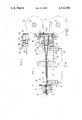
- FIG. 1 is a diagrammatic view and part section of a wire guide and supply system used with a stapler.
- FIG. 2 is a view of one example for a simple drive for the capstan of the change-over system in keeping with FIG. 1.
- the general design and workings of staplers for stapling folded products made up of separate sheets using wire staples are known to those versed in the art so that no full account thereof is needed here.
- a stapler gets wire from a supply reel, that is to say, the wire is pulled off from the reel as needed and transported to the stapler.
- the wire supply system to be seen in FIG. 1 is made up of a feed unit 1 and a reel support 2. These two assemblies are themselves supported on parts 3 and 4 on the inside and on the outside of a side wall 6 of the stapler, the wall 6 having a wire opening 5 that is aligned therewith on single axis.
- the feed unit 1 has two feed rollers 7 and 8 between which the wire is run before it is made into staples.
- the one feed roller 8 is supported on a bearing on a lever 9, that is pressed downwards by an adjustable loading spring 10 for gripping the wire against the other feed roller 7.
- the feed roller 8 may be lifted clear of the lower roller 7 (whose axis is stationary) against the effect of the spring 10 by way of a servo 11 in the form of a fluid power actuator. By putting the servo 11 into operation and taking it out of operation the supply of wire may be cut off without the drive for the feed rollers 7 and 8 having to be stopped.
- an inlet guide pipe 12 so placed and designed that the start or front end of a length of wire to be supplied between the feed rollers 7 and 8 may in fact be run in between them under full control so that one may be certain that such wire is in fact transported by the feed rollers.
- a cutting pipe 13 or nipple On the side of the rollers 7 and 8 opposite to the inlet guide pipe 12 there is a cutting pipe 13 or nipple, whose left hand end has the function of a stationary knife for use with a moving knife 14, that is run up and down across such face cutting the wire to lengths that are dependent on the timing of the knife 14. The lengths are equal to the size of the staples.
- the reel support 2 or chair has reel support pins 15 for two reels 16 and 17 of wire, that is to say cores or bobbins with wire wound thereon.
- the cores may be in the form of simple resin bobbins whose inner tubes are able to be freely turned on the supporting pins 15. Wire is first taken from one reel and then from the other so that while one reel is being used up, another reel may be put in place and readied. In the condition to be seen in FIG. 1, the reel 17 is supplying the wire 18 that for this reason is being gripped between the feed rollers 7 and 8 of the feed unit 1.
- the wire 19 taken from the other reel 16 is fixed in position so that its front end 20 or start is in a waiting or ready position short of the feed unit 1.
- the wire feed is stopped, the last length of wire that is still being gripped by the feed unit 1 is pulled out backwards from the feed unit and at the same time the start 20 of the wire, unreeled from the reel 16, is run into the feed unit 1.
- the feed unit 1 it is now possible for the feed unit 1 to be started again by putting the rollers 7 and 8 into operation so that wire is now taken from the reel 16.
- the wire now supplied to the feed unit 1 goes through a wire guide 21 that is best in the form of a tube or pipe stretching from the reel support 2 and the feed unit 1.
- the wire guide 21 is forked or branched to the right of the stapler side wall 6 (outside it) as two branches 21a and 21b running towards the two reels 16 and 17.
- a change-over unit 22 For speeding up reel change-over there is a change-over unit 22, that in the present case has the branches 21a and 21b running through it, and which is united with the reel support 2.
- the unit 22 is in the present working example made up of a capstan 23 supported for turning about a stationary axis and two diametrically opposite (with respect to a diameter of the capstan 23, that is) pinch rollers 24 for acting on the outer face of the capstan 23 and gripping the wire thereagainst with the wire at a tangent to the capstan so that the wire (18 or 19) may be pushed along because the capstan 23 is turning.
- one wire will be moved in one direction and the other wire in the opposite direction, the direction of turning being controlling as to which wire is moved forwards into a waiting position and which is pulled backwards for taking wire from the new, full reel and pushing wire back towards the used reel.
- the direction of the capstan 23 is changed over each time reels are exchanged as a new full reel is placed on one of the pins 15 and then, the next time, on the other pin while the used up reel is in each case on the other pin 15.
- the capstan 23 is joined up by a shaft 25 with a handwheel having a handle 26 and furthermore a round plate 28 resting against the housing 27 of the change-over unit.
- This plate 28 has a curved groove 29 running around its axis for a limited angle and having a pin 30 (fixed to the housing) taken up in it.
- the capstan 23 may for this reason only be turned till one or the other end of the groove 29 has run up against the pin 30 acting as a fixed stop. And then it will not be possible for the capstan to go on being turned in the same direction and it may only be turned back in the opposite direction.
- This design in fact makes certain that the capstan 23 may only be turned to a limited degree in the one direction.
- the length or angle of the curved, coaxial groove 29 is in fact controlling for the degree of turning of the said capstan 23 and the wire 18 or 19, whichever may be the case, is only moved to a limited, regular degree.
- the capstan 23 is designed with such a diameter that the angle of turning, as dependent on the length of the curved groove 29, is responsible for such a degree of transport of the wire that the start 20 of the wire 19 in the waiting or ready position may be certainly gripped by the feed rollers 7 and 8 and at the same time one may be certain of clearing the rest 18 of the used wire completely from the cutting pipe 13 and inlet guide 12. This is made possible inasfar as the distance between the ends, furthest from each other, is somewhat smaller than the distance between the front end 20 of the piece of wire 19 in the ready position and the nip of the feed rollers 7 and 8, this distance in turn being dependent on the angle of turning of the capstan 23 and its diameter, in the change-over unit 22.
- the length which the wire is to be moved in at the wire guide 21 is measured and " memorized" on the wire (in the present case the wire 19) by fixing a gripper 31 on the wire.
- the wire may then simply be pushed into the wire guide 21 as far as the gripper will let it, that is to say when the gripper has come up against a stop, in the present case the housing of the change-over unit 22. It would however be possible for the wire guide to have a window or for all of it to be made of glass-clear material.
- each wire guide branch 21a and 22b has a brake 32 and in the present case each such brake is made up of two brake rollers 33 that are braked and not turned readily. They are forced onto the wire running between them by a loading spring in each case. It is best if the design is such that one roller of each two rollers may be pulled back clear of the wire so as to make it simpler for the end of a new supply of wire to be threaded into the desired position. In the system the moving roller in each case is simply fixed to one end of a sliding rod 34.
- the pinch rollers 24 acting against the capstan 23 and bearinged on levers 35 are designed stretching out to the left past their turnpins as arms 36.
- their arms 36 are pressed in an opening direction, this being done by a servo 37, fixed on one of the arms 36, in the form of a simple fluid power actuator.
- a servo 37 fixed on one of the arms 36, in the form of a simple fluid power actuator.
- On working the actuator or servo 37 its piston rod is moved out aginst the other arm 36.
- the fluid supply lines 38 running to the servos 11 and 37 are turned on and off using a common control valve 39.
- This control valve 39 may be so changed that, at the same time, the feed roller 8 is lifted clear of the other feed roller 7 so that the feed unit 1 is turned off and the pinch rollers 24 are forced against the capstan 23 so that on turning the driving capstan the one wire may be moved forwards and the other wire may be pulled back as desired.
- the decrease in diameter of the reel (in FIG. 1, the reel 17) from which wire is being taken is monitored by a sensing system, as for example a photoelectric system or the like.
- a simple mechanical feeler 40 is used that gives a signal once the wire is running out and the control valve 39 is worked thereby.
- the empty reel (that is to say reel core or bobbin) 17 may be taken down and its place taken by a full reel.
- the end of the wire on this new reel 17 is threaded inwards as far as the ready position even while the apparatus is still running.
- the next time the reels have to be changed over it will then be this wire that is moved into the feed unit 1 and the other wire (19) pulled back, for which purpose the capstan 23 is turned clockwise.
- the presence of the curved groove 29 makes it simpler to see which direction the capstan has to be turned in.
- control valve 39 is designed so that it may be worked by hand.
- the valve 39 might be a solenoid valve that would be put into operation together with a driving motor for the capstan 23 by way of the monitoring system 40.
- the drive motor for the capstan would then simply be a synchronous motor which would be able to be reversed.
- a limit switch may be present that is worked thereby, such limit switch turning off the driving motor and at the same time putting the control valve 39 out of operation.
Landscapes
- Engineering & Computer Science (AREA)
- Mechanical Engineering (AREA)
- Life Sciences & Earth Sciences (AREA)
- Forests & Forestry (AREA)
- Dovetailed Work, And Nailing Machines And Stapling Machines For Wood (AREA)
Applications Claiming Priority (2)
| Application Number | Priority Date | Filing Date | Title |
|---|---|---|---|
| DE3210014 | 1982-03-19 | ||
| DE3210014A DE3210014C2 (de) | 1982-03-19 | 1982-03-19 | Vorrichtung zum Zuführen von Klammerdraht zu einer Klammerbildungseinrichtung |
Publications (1)
| Publication Number | Publication Date |
|---|---|
| US4512506A true US4512506A (en) | 1985-04-23 |
Family
ID=6158672
Family Applications (1)
| Application Number | Title | Priority Date | Filing Date |
|---|---|---|---|
| US06/470,786 Expired - Lifetime US4512506A (en) | 1982-03-19 | 1983-03-01 | System for the supply of staple wire to a stapler |
Country Status (4)
| Country | Link |
|---|---|
| US (1) | US4512506A (de) |
| EP (1) | EP0089591B1 (de) |
| JP (1) | JPS5998806A (de) |
| DE (2) | DE3210014C2 (de) |
Cited By (7)
| Publication number | Priority date | Publication date | Assignee | Title |
|---|---|---|---|---|
| US4750661A (en) * | 1985-06-14 | 1988-06-14 | Officine Meccaniche Giovani Cerutti S.P.A. | Apparatus for applying staples to groups of signatures and the like |
| US5065930A (en) * | 1986-07-07 | 1991-11-19 | Kennedy George W | Spiral feed fastener |
| US5590828A (en) * | 1994-07-06 | 1997-01-07 | Ferag Ag | Apparatus for the wire-stapling of printed products |
| US5655427A (en) * | 1994-05-25 | 1997-08-12 | Ferag Ag | Stapling device with rotary cutting element |
| US20050067455A1 (en) * | 2003-09-26 | 2005-03-31 | Duff William G. | Staple-forming apparatus |
| CN111199815A (zh) * | 2018-11-19 | 2020-05-26 | 波音公司 | 将线缆馈入线缆处理设备的系统、方法和装置 |
| US11070019B2 (en) | 2018-11-19 | 2021-07-20 | The Boeing Company | System for processing an end of a cable |
Families Citing this family (4)
| Publication number | Priority date | Publication date | Assignee | Title |
|---|---|---|---|---|
| US4841498A (en) * | 1985-03-11 | 1989-06-20 | Matsushita Electric Industrial Co., Ltd. | Information recording/reproducing apparatus with means for substituting predetermined good sectors for defective ones |
| US5333438A (en) * | 1992-11-06 | 1994-08-02 | Signode Corporation | Dual coil power strapping machine |
| DE19712863C2 (de) * | 1997-03-27 | 2001-01-25 | Eastman Kodak Co | Verfahren und Vorrichtung zum Betreiben eines Geräts zum Heften von Blättern |
| CN111573379A (zh) * | 2020-05-21 | 2020-08-25 | 桐乡市钛铪铖纺织机械有限公司 | 一种数控衬纸机 |
Citations (2)
| Publication number | Priority date | Publication date | Assignee | Title |
|---|---|---|---|---|
| GB1074198A (en) * | 1963-11-08 | 1967-06-28 | Winkler Fallert & Co Maschf | A method and apparatus for the formation of wire staples |
| US4318555A (en) * | 1980-01-15 | 1982-03-09 | Eastman Kodak Company | Stapler |
Family Cites Families (3)
| Publication number | Priority date | Publication date | Assignee | Title |
|---|---|---|---|---|
| DE756731C (de) * | 1940-06-16 | 1953-01-26 | Vomag Vogtlaendische Maschinen | Vorrichtung zum selbsttaetigen Umschalten der Drahtheftvorrichtungen, insbesondere von Rotationsdruckmaschinen, von der ablaufenden auf die Ersatzdrahtrolle |
| DD100437A1 (de) * | 1972-11-17 | 1973-09-20 | ||
| DD151426A1 (de) * | 1980-06-17 | 1981-10-21 | Rudolf Stoerr | Nonstop-drahtzufuehr-vorrichtung fuer heftapparate |
-
1982
- 1982-03-19 DE DE3210014A patent/DE3210014C2/de not_active Expired
-
1983
- 1983-03-01 US US06/470,786 patent/US4512506A/en not_active Expired - Lifetime
- 1983-03-12 DE DE8383102464T patent/DE3372853D1/de not_active Expired
- 1983-03-12 EP EP83102464A patent/EP0089591B1/de not_active Expired
- 1983-03-17 JP JP58045822A patent/JPS5998806A/ja active Pending
Patent Citations (2)
| Publication number | Priority date | Publication date | Assignee | Title |
|---|---|---|---|---|
| GB1074198A (en) * | 1963-11-08 | 1967-06-28 | Winkler Fallert & Co Maschf | A method and apparatus for the formation of wire staples |
| US4318555A (en) * | 1980-01-15 | 1982-03-09 | Eastman Kodak Company | Stapler |
Cited By (11)
| Publication number | Priority date | Publication date | Assignee | Title |
|---|---|---|---|---|
| US4750661A (en) * | 1985-06-14 | 1988-06-14 | Officine Meccaniche Giovani Cerutti S.P.A. | Apparatus for applying staples to groups of signatures and the like |
| US5065930A (en) * | 1986-07-07 | 1991-11-19 | Kennedy George W | Spiral feed fastener |
| US5655427A (en) * | 1994-05-25 | 1997-08-12 | Ferag Ag | Stapling device with rotary cutting element |
| US5590828A (en) * | 1994-07-06 | 1997-01-07 | Ferag Ag | Apparatus for the wire-stapling of printed products |
| US20050067455A1 (en) * | 2003-09-26 | 2005-03-31 | Duff William G. | Staple-forming apparatus |
| US7159746B2 (en) | 2003-09-26 | 2007-01-09 | Duff William G | Staple-forming apparatus |
| US20070119898A1 (en) * | 2003-09-26 | 2007-05-31 | Duff William G | Staple-forming apparatus |
| CN111199815A (zh) * | 2018-11-19 | 2020-05-26 | 波音公司 | 将线缆馈入线缆处理设备的系统、方法和装置 |
| EP3674237A1 (de) * | 2018-11-19 | 2020-07-01 | The Boeing Company | System und vorrichtung zum zuführen von kabeln in kabelverarbeitungsgeräte |
| US11070007B2 (en) | 2018-11-19 | 2021-07-20 | The Boeing Company | System configured to position a tip of a cable |
| US11070019B2 (en) | 2018-11-19 | 2021-07-20 | The Boeing Company | System for processing an end of a cable |
Also Published As
| Publication number | Publication date |
|---|---|
| DE3210014A1 (de) | 1983-10-06 |
| EP0089591A2 (de) | 1983-09-28 |
| EP0089591B1 (de) | 1987-08-05 |
| DE3372853D1 (en) | 1987-09-10 |
| EP0089591A3 (en) | 1985-12-27 |
| JPS5998806A (ja) | 1984-06-07 |
| DE3210014C2 (de) | 1985-05-15 |
Similar Documents
| Publication | Publication Date | Title |
|---|---|---|
| US20210122076A1 (en) | Method and machine for cutting logs of wound web material | |
| KR101696319B1 (ko) | 광케이블 자동배출 권선시스템 | |
| CA1073424A (en) | Output unit of web treating machines, as for example printing machines and the like | |
| US7775476B2 (en) | Rewinding machine to rewind web material on a core for rolls and corresponding method of winding | |
| US4512506A (en) | System for the supply of staple wire to a stapler | |
| KR0134890B1 (ko) | 롤절단기계 | |
| EP0292924A1 (de) | Bahn-Aufwickelapparat mit Bahnübergabe ohne Trennschnitt | |
| US3891158A (en) | Method and apparatus for splicing a standby web to a running web | |
| GB1567359A (en) | Driven nip roll splicer | |
| DE3150575A1 (de) | Bandzufuehrsystem | |
| EP2964555A1 (de) | Wickelmaschine und verfahren zur herstellung von bahnmaterialrollen | |
| KR20170039163A (ko) | 웹 재료의 로그를 제조하기 위한 재권취기 및 방법 | |
| US3915398A (en) | Automatic doffing apparatus | |
| CN107364752B (zh) | 具有对准系统的用于生产线轴的机器和方法 | |
| US5456098A (en) | Process and apparatus for controlling the loading of a processing machine with band-like material | |
| EP0625474A1 (de) | Rollenwechselvorrichtung zum Zuführen von bandenförmigem Material zu einer Bearbeitungsmaschine | |
| US4414048A (en) | Web splicing apparatus | |
| JP2019532886A (ja) | 巻取り終わりにストリップを横方向に切断する手段を備えたウェブ材料のストリップ巻取り装置及び方法 | |
| EP1648805B1 (de) | Verfahren und vorrichtung zum spleissen von bahnen | |
| US5305965A (en) | Apparatus for winding and storing a tape-like article in a container | |
| US5240196A (en) | Cutting and feeding apparatus for webs of material on winding machines | |
| US4141515A (en) | Automated layer separator delivery system for optical waveguide winding | |
| US3096947A (en) | Web severing and roll initiating mechanism | |
| US20200009847A1 (en) | Plant and process for the production of paper logs | |
| US4648927A (en) | Method and device for production of cover strips for insertion into the grooves of stators of electric machines |
Legal Events
| Date | Code | Title | Description |
|---|---|---|---|
| AS | Assignment |
Owner name: ALBERT- FRANKENTHAL AG, 6710 FRANKENTHAL, WEST GER Free format text: ASSIGNMENT OF ASSIGNORS INTEREST.;ASSIGNOR:FISCHER, EMIL;REEL/FRAME:004102/0114 Effective date: 19830118 |
|
| STCF | Information on status: patent grant |
Free format text: PATENTED CASE |
|
| FPAY | Fee payment |
Year of fee payment: 4 |
|
| FPAY | Fee payment |
Year of fee payment: 8 |
|
| FEPP | Fee payment procedure |
Free format text: PAYOR NUMBER ASSIGNED (ORIGINAL EVENT CODE: ASPN); ENTITY STATUS OF PATENT OWNER: LARGE ENTITY |
|
| FPAY | Fee payment |
Year of fee payment: 12 |