US4500032A - Method and apparatus for proper registration of mating parts - Google Patents
Method and apparatus for proper registration of mating parts Download PDFInfo
- Publication number
- US4500032A US4500032A US06/467,082 US46708283A US4500032A US 4500032 A US4500032 A US 4500032A US 46708283 A US46708283 A US 46708283A US 4500032 A US4500032 A US 4500032A
- Authority
- US
- United States
- Prior art keywords
- pattern
- station
- mating
- gage
- head assembly
- Prior art date
- Legal status (The legal status is an assumption and is not a legal conclusion. Google has not performed a legal analysis and makes no representation as to the accuracy of the status listed.)
- Ceased
Links
Images


Classifications
-
- H—ELECTRICITY
- H05—ELECTRIC TECHNIQUES NOT OTHERWISE PROVIDED FOR
- H05K—PRINTED CIRCUITS; CASINGS OR CONSTRUCTIONAL DETAILS OF ELECTRIC APPARATUS; MANUFACTURE OF ASSEMBLAGES OF ELECTRICAL COMPONENTS
- H05K13/00—Apparatus or processes specially adapted for manufacturing or adjusting assemblages of electric components
- H05K13/04—Mounting of components, e.g. of leadless components
- H05K13/0404—Pick-and-place heads or apparatus, e.g. with jaws
- H05K13/0413—Pick-and-place heads or apparatus, e.g. with jaws with orientation of the component while holding it; Drive mechanisms for gripping tools, e.g. lifting, lowering or turning of gripping tools
-
- H—ELECTRICITY
- H05—ELECTRIC TECHNIQUES NOT OTHERWISE PROVIDED FOR
- H05K—PRINTED CIRCUITS; CASINGS OR CONSTRUCTIONAL DETAILS OF ELECTRIC APPARATUS; MANUFACTURE OF ASSEMBLAGES OF ELECTRICAL COMPONENTS
- H05K13/00—Apparatus or processes specially adapted for manufacturing or adjusting assemblages of electric components
- H05K13/04—Mounting of components, e.g. of leadless components
- H05K13/0404—Pick-and-place heads or apparatus, e.g. with jaws
- H05K13/0408—Incorporating a pick-up tool
-
- H—ELECTRICITY
- H05—ELECTRIC TECHNIQUES NOT OTHERWISE PROVIDED FOR
- H05K—PRINTED CIRCUITS; CASINGS OR CONSTRUCTIONAL DETAILS OF ELECTRIC APPARATUS; MANUFACTURE OF ASSEMBLAGES OF ELECTRICAL COMPONENTS
- H05K13/00—Apparatus or processes specially adapted for manufacturing or adjusting assemblages of electric components
- H05K13/04—Mounting of components, e.g. of leadless components
- H05K13/043—Feeding one by one by other means than belts
- H05K13/0439—Feeding one by one by other means than belts incorporating means for treating the terminal leads only before insertion
Definitions
- the invention is in the field of handling articles having bodies and members protruding therefrom, particularly such articles as electronic components having bodies and depending leads.
- a particular pattern of one or more leads is known, and spacing tolerances between leads of a particular pattern are exact enough for insertion into a corresponding hole pattern of a circuit board.
- irregularities can and do occur such that the body profile may become offset relative to the lead pattern in X, Y, ⁇ or combinations thereof and result in a variation of the orientation and location of the lead pattern relative to the profile of the body.
- Such variation may occur between batches of components or from component to component in a particular batch.
- Such an offset between the body profile and the lead pattern presents problems in proper insertion of the leads into a corresponding pattern of circuit board holes during subsequent handling of the component.
- a "nominal" pattern is one in which there is no relative offset of the body profile from a defined pattern; and an “actual” pattern is one in which there may or may not be such a relative offset.
- an offset of the "actual" lead pattern of a component from the "nominal" lead pattern which that component should have can be said to include the above-described irregularities.
- the pattern need not be one of leads extending from the body. Rather, it may be a pattern of recesses or holes in the body which are to be mated with protruding members of another body.
- a first body may have a mixed pattern of holes and leads for mating with a corresponding mixed pattern of holes and leads of a second body.
- a component handling device is mountable upon known X, Y, Z-translatable robot arms or the like and provides "wrist” manipulation such that the device may assume various pick-up and insertion attitudes.
- the device has a gripper assembly which is "floatable" within a head assembly such that a component may be oriented according to the lead pattern for subsequent insertion into a corresponding hole pattern without regard to X, Y, and ⁇ offsets of the lead pattern relative to the component body.
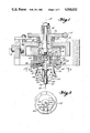
- FIG. 1 schematically illustrates, in cross-section, a side view of a device of the instant invention.
- FIG. 2 is a schematic cross-section, as viewed approximately along arrows 2--2 of FIG. 1.
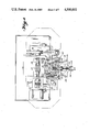
- FIG. 3 is a detailed, top plan view of a device of the instant invention, with portions thereof broken away.
- FIG. 4 is a front view, partially in section, as viewed approximately along the arrows 3--3 of FIG. 3.
- FIG. 5 is a left side, cross-sectional view of the device of FIG. 4.
- FIG. 6 is a left side elevation of the device of FIG. 3.
- FIG. 7 is a right side elevation of the device of FIG. 3.
- FIG. 8 schematically illustrates a component having a lead pattern which is offset in Y and ⁇ .
- FIG. 9 schematically illustrates a component having a lead pattern offset in ⁇ , and a corresponding hole pattern indicated in phantom.
- FIG. 10 is an isometric view of one embodiment of a lead gauging, guiding, and straightening device.
- FIG. 11 is an enlarged view, approximately along the arrows 11--11 of FIG. 10, to illustrate the guiding feature of the gauging device of FIG. 10.
- FIG. 12 is an isometric view illustrating connection of an electrical component to the pads of a circuit board by means of solder bumps.
- FIG. 8 schematically illustrates an exaggerated offset of a component body 70 from a lead pattern comprising leads 72.
- the lead pattern is offset in ⁇ and Y relative to the profile of body 70.
- FIG. 12 illustrates a component mounting arrangement in which an electrical component 100 has one or more solder bumps 102 depending therefrom in order to provide electrical and mechanical connection of the component to corresponding conductive pads 104 of circuit board 106 via solder bumps 102.
- the actual pattern of solder bumps 102 may be offset in ⁇ , X, and Y relative to a nominal pattern thereof.
- leads 72' comprise a row-type lead pattern having axis 78 for insertion into holes 76 having a corresponding row-type hole pattern axis 80.
- lead pattern axis 78 is offset relative to the profile of component 70' and to hole pattern axis 80 by an amount ⁇ .
- dimension b is a projected distance between the centers of the end leads of the lead pattern and is equal to 0.026 inches.
- FIG. 1 discloses a translation assembly attachable to any number of well-known X, Y, Z-manipulatable robot arms, and which is further manipulatable about axes 12 and 13 in order to provide a "wrist" action.
- the device of FIG. 1 is illustrated in more detail in FIGS. 3-7, from which it may be seen that housing 10 is pivotal about axes 13 with adjustment for a stop position being provided by machine screw 11.
- housing 10 for rotation about axes 12 is cylinder 14 having fluid inlet/outlet 15 for communication with the interior thereof.
- Cylinder 14 is keyed to a worm gear 19 by means of key 18 such that rotation of worm 17 will rotate worm gear 19 which, in turn, rotates cylinder 14.
- Bearing 16 allows relative rotation between gear 19 and housing 10.
- Received within cylinder 14 is piston portion 26 of head assembly 20.
- Keys 22 prevent rotation of head assembly 20 about axis 12 relative to cylinder 14, such that head assembly 20 is extensible from cylinder 14 by applying fluid through opening 15, and is retractable by means of spring 32.
- Head assembly 20 is a combined piston and air chamber, comprising the above-mentioned piston portion 26 and air chamber 24 having fluid passage 29.
- Gripper assembly 40 has upper portion 42 and flange portion 44 such that gripper assembly 40 is "floatable" for movement in X, Y, and ⁇ of a coordinate system within a plane perpendicular to axes 12 and defined by bearing plate 45. Having achieved such movement of gripper assembly 40 relative to head assembly 20, fluid pressure may be applied through inlet 29 in order to lock of fix gripper assembly 40 relative to head assembly 20 by forcing flange 44 against bearing plate 45.
- Compression springs 28 provide for recentering of gripper assembly 40 about axis 12 upon removal of fluid pressure from air chamber 24. Such centering springs are omittable from the device, but do find application in preventing "bottoming out” of gripper assembly 40 relative to head assembly 20, i.e., when housing 10 is rotated 90° about axes 13 from the position shown in FIG. 1.
- gripper brackets 46 which support grippers 50 for pivoting about pivot axes 47.
- Grippers 50 have portions 54 for gripping the body of a component 70 and are normally biased to an open position by means of tension springs 56.
- gripper assembly 40 is further provided with a cylinder portion 43, within which is received a gripper actuator 58 comprising piston portion 60 and actuator cam 62.
- Gripper actuator 58 is stroked by means of fluid application and evacuation via fluid inlets 48 and 49.
- Grippers 50 have cam portions 52 engageable by actuator cam 62, when gripper actuator 58 is retracted, such that grippers 50 pivot above axes 47 and gripper portions 54 securely grip the body 70 of a component.
- Telescopic within gripper actuator 58 is a pusher 64 biased to an extended position by compression spring 66 and limited in its extension by ring 68. The function of pusher 64 will be better appreciated from the following description of the operation of the device.
- a robotic arm or the like transports the device of FIG. 1 to a component pick-up station at which the device is oriented and actuated to grip the body 70 of the component by grippers 50.
- gripper assembly 40 may be fixed or floating relative to head assembly 20.
- the device of FIG. 1 is moved to a gauging station.
- a gauge 90 having gauge holes 92 (FIG. 10) is located and is useable with either of the lead patterns illustrated in FIGS. 8 and 9.
- gauge 90 is oriented and located such that, upon mating of the leads of a component with the appropriate holes of gauge 90, standard robotic or automated insertion machine controls, i.e., numerical control, may be used to transfer the component to a position above and in alignment with a corresponding hole pattern of a circuit board.
- Holes 92 of gauge 90 are provided with inverted conical depressions 96 having a sufficient conical base opening to receive the leads of a component whose actual lead pattern is offset from a nominal lead pattern during manufacture of the component. Further, those components which do not have such an offset often have one or more leads which are slightly bent away from their intended longitudinal axes. With such bent leads, lead-in portion 96 of holes 92 will facilitate straightening of bent leads upon insertion into holes 92.
- gripper fingers 54 are released from engagement with component 70 and the leads of the component are inserted into holes 92 of gauge 90 under the influence of guiding portions 96 and spring biased pusher 64.
- the lead pattern is exactly located relative to the position programmable head assembly 20, whereas the body, which is offset relative to the lead pattern, is not.
- head assembly 20 is lowered and grippers 50 are actuated to cause gripper portions 54 to engage the body 70 and, thus, to cause gripper assembly 44 to float relative to head assembly 20.
- gripper assembly 40 Although only two grippers 50 are illustrated in the drawings, it is contemplated that three or more fingers, located in different orientations about axes 12, could be mounted on gripper assembly 40, according to various profiles of the bodies to be handled by the device. Having "floated" gripper assembly 40 in X, Y, ⁇ or combinations thereof, fluid is applied to chamber portion 24 of head assembly 20 to lock gripper assembly 40 relative to head assembly 20. Having provided the proper orientation of the lead pattern of the component relative to head assembly 20, the component is then picked up from gauge 90 and transferred a programmed distance for insertion of the leads into a corresponding hole pattern.
- the particular location of the hole pattern is programmable as well as the particular location of pickup of the component.
- the body profile is offset relative to the lead pattern of a particular component, a situation which is not readily programmable.
- the bodies of some components are not easily adaptable to vacuum pickup.
Landscapes
- Engineering & Computer Science (AREA)
- Manufacturing & Machinery (AREA)
- Microelectronics & Electronic Packaging (AREA)
- Supply And Installment Of Electrical Components (AREA)
- Nitrogen Condensed Heterocyclic Rings (AREA)
- Air Bags (AREA)
- Lining Or Joining Of Plastics Or The Like (AREA)
Priority Applications (7)
| Application Number | Priority Date | Filing Date | Title |
|---|---|---|---|
| US06/467,082 US4500032A (en) | 1983-02-16 | 1983-02-16 | Method and apparatus for proper registration of mating parts |
| AT83306623T ATE42167T1 (de) | 1983-02-16 | 1983-10-31 | Verfahren und apparat zum richtigen ineinanderstecken von zu verbindenden teilen. |
| EP83306623A EP0120159B1 (fr) | 1983-02-16 | 1983-10-31 | Méthode et appareil pour l'insertion correcte l'une dans l'autre de parties à accoupler |
| DE8383306623T DE3379631D1 (en) | 1983-02-16 | 1983-10-31 | Method and apparatus for proper registration of mating parts |
| CA000441719A CA1194293A (fr) | 1983-02-16 | 1983-11-22 | Methode et dispositif de mise a joint |
| JP59025316A JPS59156000A (ja) | 1983-02-16 | 1984-02-15 | 噛合い部品の適切な整合を行なう為の方法及び装置 |
| US07/532,633 USRE33641E (en) | 1983-02-16 | 1990-06-04 | Method and apparatus for proper registration of mating parts |
Applications Claiming Priority (1)
| Application Number | Priority Date | Filing Date | Title |
|---|---|---|---|
| US06/467,082 US4500032A (en) | 1983-02-16 | 1983-02-16 | Method and apparatus for proper registration of mating parts |
Related Child Applications (1)
| Application Number | Title | Priority Date | Filing Date |
|---|---|---|---|
| US07/532,633 Reissue USRE33641E (en) | 1983-02-16 | 1990-06-04 | Method and apparatus for proper registration of mating parts |
Publications (1)
| Publication Number | Publication Date |
|---|---|
| US4500032A true US4500032A (en) | 1985-02-19 |
Family
ID=23854269
Family Applications (1)
| Application Number | Title | Priority Date | Filing Date |
|---|---|---|---|
| US06/467,082 Ceased US4500032A (en) | 1983-02-16 | 1983-02-16 | Method and apparatus for proper registration of mating parts |
Country Status (6)
| Country | Link |
|---|---|
| US (1) | US4500032A (fr) |
| EP (1) | EP0120159B1 (fr) |
| JP (1) | JPS59156000A (fr) |
| AT (1) | ATE42167T1 (fr) |
| CA (1) | CA1194293A (fr) |
| DE (1) | DE3379631D1 (fr) |
Cited By (15)
| Publication number | Priority date | Publication date | Assignee | Title |
|---|---|---|---|---|
| US4553311A (en) * | 1983-12-22 | 1985-11-19 | The Perkin-Elmer Corporation | Chuck handling device |
| US4720035A (en) * | 1986-01-17 | 1988-01-19 | Fujitsu Limited | Method of reflow bonding electronic parts on printed circuit board and apparatus used therefor |
| US4735354A (en) * | 1986-09-19 | 1988-04-05 | Toyo Electronics Corp. | Method of soldering component on printed circuit board |
| US4789292A (en) * | 1984-04-06 | 1988-12-06 | Holcomb Gregory W | End effector for robotic equipment |
| US4828162A (en) * | 1988-02-29 | 1989-05-09 | Hughes Aircraft Company | Moving jaw reflow soldering head |
| EP0318068A1 (fr) | 1985-05-16 | 1989-05-31 | Gregory W. Holcomb | Appareil pour redresser les pattes de composants |
| US4876791A (en) * | 1986-04-22 | 1989-10-31 | Kulicke & Soffa Industries, Inc. | Apparatus for and methods of die bonding |
| US4910859A (en) * | 1984-04-06 | 1990-03-27 | Holcomb Gregory W | Circuit assembly system |
| US5509161A (en) * | 1990-04-11 | 1996-04-23 | Kaysersberg | Impregnation procedure for a textile sheet |
| US6622902B2 (en) * | 2000-12-19 | 2003-09-23 | Mirae Corporation | Nozzle apparatus for surface mount device |
| US20040066514A1 (en) * | 2002-10-08 | 2004-04-08 | Kardos Victor J. | Upper compliant tooling |
| US20060119026A1 (en) * | 2004-12-07 | 2006-06-08 | Ryaboy Vyacheslav M | Methods and devices for active vibration damping of an optical structure |
| US7320455B2 (en) | 2003-10-24 | 2008-01-22 | Newport Corporation | Instrumented platform for vibration-sensitive equipment |
| US8857585B2 (en) | 2010-12-29 | 2014-10-14 | Newport Corporation | Tunable vibration dampers and methods of manufacture and tuning |
| US11202374B2 (en) * | 2017-03-06 | 2021-12-14 | Panasonic Intellectual Property Management Co., Ltd. | Method of mounting component |
Families Citing this family (3)
| Publication number | Priority date | Publication date | Assignee | Title |
|---|---|---|---|---|
| US4633584A (en) * | 1985-02-20 | 1987-01-06 | Molex Incorporated | Accurate positioning of solid components for a robotic pickup |
| DE3934291C1 (en) * | 1989-10-13 | 1991-04-18 | Roederstein Spezialfabriken Fuer Bauelemente Der Elektronik Und Kondensatoren Der Starkstromtechnik Gmbh, 8300 Landshut, De | Electronic components, e.g. capacitors, on PCB mounting device - has vertically shiftable component holder with clamping or grasping brackets and moved by robot |
| JP2558076Y2 (ja) * | 1990-03-02 | 1997-12-17 | 株式会社ユーシン | スイッチ |
Citations (6)
| Publication number | Priority date | Publication date | Assignee | Title |
|---|---|---|---|---|
| US2696746A (en) * | 1951-06-21 | 1954-12-14 | Saul J Hoffman | Straightening tool for terminal plugs |
| US3559279A (en) * | 1968-10-14 | 1971-02-02 | Sperry Rand Corp | Method for bonding the flip-chip to a carrier substrate |
| US3687172A (en) * | 1970-10-07 | 1972-08-29 | Signetics Corp | Lead straightener and method |
| US3946931A (en) * | 1974-11-27 | 1976-03-30 | Western Electric Company, Inc. | Methods of and apparatus for bonding an article to a substrate |
| US4215469A (en) * | 1977-09-29 | 1980-08-05 | Fuji Mgf. Co., Ltd. | Method of inserting electronic components to a printed circuit board |
| US4434550A (en) * | 1980-11-28 | 1984-03-06 | Blaupunkt-Werke Gmbh | Method and apparatus for insertion of electrical components into a circuit board |
Family Cites Families (3)
| Publication number | Priority date | Publication date | Assignee | Title |
|---|---|---|---|---|
| DE2031241B1 (de) * | 1970-06-24 | 1971-12-09 | Siemens Ag | Vorrichtung zum Bestucken von elektn sehen Bauteiletragern |
| JPS5789535A (en) * | 1980-11-20 | 1982-06-03 | Sanyo Electric Co Ltd | Device for correcting mounted posture of part |
| JPS5815294A (ja) * | 1981-07-20 | 1983-01-28 | 日本電気株式会社 | 集積回路実装装置 |
-
1983
- 1983-02-16 US US06/467,082 patent/US4500032A/en not_active Ceased
- 1983-10-31 AT AT83306623T patent/ATE42167T1/de not_active IP Right Cessation
- 1983-10-31 EP EP83306623A patent/EP0120159B1/fr not_active Expired
- 1983-10-31 DE DE8383306623T patent/DE3379631D1/de not_active Expired
- 1983-11-22 CA CA000441719A patent/CA1194293A/fr not_active Expired
-
1984
- 1984-02-15 JP JP59025316A patent/JPS59156000A/ja active Pending
Patent Citations (6)
| Publication number | Priority date | Publication date | Assignee | Title |
|---|---|---|---|---|
| US2696746A (en) * | 1951-06-21 | 1954-12-14 | Saul J Hoffman | Straightening tool for terminal plugs |
| US3559279A (en) * | 1968-10-14 | 1971-02-02 | Sperry Rand Corp | Method for bonding the flip-chip to a carrier substrate |
| US3687172A (en) * | 1970-10-07 | 1972-08-29 | Signetics Corp | Lead straightener and method |
| US3946931A (en) * | 1974-11-27 | 1976-03-30 | Western Electric Company, Inc. | Methods of and apparatus for bonding an article to a substrate |
| US4215469A (en) * | 1977-09-29 | 1980-08-05 | Fuji Mgf. Co., Ltd. | Method of inserting electronic components to a printed circuit board |
| US4434550A (en) * | 1980-11-28 | 1984-03-06 | Blaupunkt-Werke Gmbh | Method and apparatus for insertion of electrical components into a circuit board |
Cited By (17)
| Publication number | Priority date | Publication date | Assignee | Title |
|---|---|---|---|---|
| US4553311A (en) * | 1983-12-22 | 1985-11-19 | The Perkin-Elmer Corporation | Chuck handling device |
| US4789292A (en) * | 1984-04-06 | 1988-12-06 | Holcomb Gregory W | End effector for robotic equipment |
| US4910859A (en) * | 1984-04-06 | 1990-03-27 | Holcomb Gregory W | Circuit assembly system |
| EP0318068A1 (fr) | 1985-05-16 | 1989-05-31 | Gregory W. Holcomb | Appareil pour redresser les pattes de composants |
| US4720035A (en) * | 1986-01-17 | 1988-01-19 | Fujitsu Limited | Method of reflow bonding electronic parts on printed circuit board and apparatus used therefor |
| US4876791A (en) * | 1986-04-22 | 1989-10-31 | Kulicke & Soffa Industries, Inc. | Apparatus for and methods of die bonding |
| US4735354A (en) * | 1986-09-19 | 1988-04-05 | Toyo Electronics Corp. | Method of soldering component on printed circuit board |
| US4828162A (en) * | 1988-02-29 | 1989-05-09 | Hughes Aircraft Company | Moving jaw reflow soldering head |
| US5509161A (en) * | 1990-04-11 | 1996-04-23 | Kaysersberg | Impregnation procedure for a textile sheet |
| US6622902B2 (en) * | 2000-12-19 | 2003-09-23 | Mirae Corporation | Nozzle apparatus for surface mount device |
| US20040066514A1 (en) * | 2002-10-08 | 2004-04-08 | Kardos Victor J. | Upper compliant tooling |
| US7320455B2 (en) | 2003-10-24 | 2008-01-22 | Newport Corporation | Instrumented platform for vibration-sensitive equipment |
| US20060119026A1 (en) * | 2004-12-07 | 2006-06-08 | Ryaboy Vyacheslav M | Methods and devices for active vibration damping of an optical structure |
| US8231098B2 (en) | 2004-12-07 | 2012-07-31 | Newport Corporation | Methods and devices for active vibration damping of an optical structure |
| US8651447B2 (en) | 2004-12-07 | 2014-02-18 | Newport Corporation | Methods and devices for active vibration damping of an optical structure |
| US8857585B2 (en) | 2010-12-29 | 2014-10-14 | Newport Corporation | Tunable vibration dampers and methods of manufacture and tuning |
| US11202374B2 (en) * | 2017-03-06 | 2021-12-14 | Panasonic Intellectual Property Management Co., Ltd. | Method of mounting component |
Also Published As
| Publication number | Publication date |
|---|---|
| EP0120159B1 (fr) | 1989-04-12 |
| CA1194293A (fr) | 1985-10-01 |
| EP0120159A3 (en) | 1986-07-02 |
| DE3379631D1 (en) | 1989-05-18 |
| JPS59156000A (ja) | 1984-09-05 |
| ATE42167T1 (de) | 1989-04-15 |
| EP0120159A2 (fr) | 1984-10-03 |
Similar Documents
| Publication | Publication Date | Title |
|---|---|---|
| US4500032A (en) | Method and apparatus for proper registration of mating parts | |
| EP1054584B1 (fr) | Appareil de garnissage en pieces et appareil d'alimentation en pieces | |
| US5446960A (en) | Alignment apparatus and method for placing modules on a circuit board | |
| US5040291A (en) | Multi-spindle pick and place method and apparatus | |
| TWI483340B (zh) | 組件對準方法及裝置 | |
| US4611397A (en) | Pick and place method and apparatus for handling electrical components | |
| US4900214A (en) | Method and apparatus for transporting semiconductor wafers | |
| JP3062517B2 (ja) | 物品整列装置 | |
| US5056844A (en) | Multiple jaw centering head structure for surface mounted component placement machines | |
| US20030014862A1 (en) | Electric-component mounting method and system | |
| USRE33641E (en) | Method and apparatus for proper registration of mating parts | |
| US4633584A (en) | Accurate positioning of solid components for a robotic pickup | |
| KR20020073274A (ko) | 실장기 및 그 부품 장착 방법 | |
| US4551913A (en) | Component delivery system | |
| KR20010039708A (ko) | 위치설정 장치 및 방법 | |
| US4917568A (en) | Suction pick-up apparatus for electrical or electronic components | |
| JP4039913B2 (ja) | 部品実装順序設定方法および部品実装順序設定装置 | |
| US4573254A (en) | Apparatus for maintaining electronic component pin alignment | |
| JPH06265324A (ja) | 電子部品実装装置及び電子部品実装状態の検査方法 | |
| JP3611400B2 (ja) | リ−ド端子付き電子部品の搬送システムにおけるプリアライメントステ−ジの位置決め方法及びハンドリング装置 | |
| JPS6363336B2 (fr) | ||
| JPH0256989A (ja) | スクリーン印刷方法及びスクリーン印刷機 | |
| JP2001102797A (ja) | 電子部品装着装置 | |
| JPS58216428A (ja) | 半導体チツプ供給装置 | |
| JPH0468125B2 (fr) |
Legal Events
| Date | Code | Title | Description |
|---|---|---|---|
| AS | Assignment |
Owner name: UNIVERSAL INSTRUMENTS CORPORATION, BINGHAMTON, N.Y Free format text: ASSIGNMENT OF ASSIGNORS INTEREST.;ASSIGNOR:ACKERMAN, DANIEL W.;REEL/FRAME:004124/0627 Effective date: 19830125 |
|
| STCF | Information on status: patent grant |
Free format text: PATENTED CASE |
|
| FEPP | Fee payment procedure |
Free format text: PAYOR NUMBER ASSIGNED (ORIGINAL EVENT CODE: ASPN); ENTITY STATUS OF PATENT OWNER: LARGE ENTITY |
|
| FPAY | Fee payment |
Year of fee payment: 4 |
|
| RF | Reissue application filed |
Effective date: 19900604 |
|
| AS | Assignment |
Owner name: DELAWARE CAPITAL FORMATION, INC., A DE CORP., DELA Free format text: ASSIGNMENT OF ASSIGNORS INTEREST.;ASSIGNOR:UNIVERSAL INSTRUMENTS CORPORATION, A DE CORP.;REEL/FRAME:006021/0159 Effective date: 19920210 |