US4440345A - Sprinkler - Google Patents
Sprinkler Download PDFInfo
- Publication number
- US4440345A US4440345A US06/179,483 US17948380A US4440345A US 4440345 A US4440345 A US 4440345A US 17948380 A US17948380 A US 17948380A US 4440345 A US4440345 A US 4440345A
- Authority
- US
- United States
- Prior art keywords
- extensions
- spray pipe
- housing
- sprinkler
- radial
- Prior art date
- Legal status (The legal status is an assumption and is not a legal conclusion. Google has not performed a legal analysis and makes no representation as to the accuracy of the status listed.)
- Expired - Lifetime
Links
Images


Classifications
-
- B—PERFORMING OPERATIONS; TRANSPORTING
- B05—SPRAYING OR ATOMISING IN GENERAL; APPLYING FLUENT MATERIALS TO SURFACES, IN GENERAL
- B05B—SPRAYING APPARATUS; ATOMISING APPARATUS; NOZZLES
- B05B3/00—Spraying or sprinkling apparatus with moving outlet elements or moving deflecting elements
- B05B3/003—Spraying or sprinkling apparatus with moving outlet elements or moving deflecting elements with braking means, e.g. friction rings designed to provide a substantially constant revolution speed
- B05B3/005—Spraying or sprinkling apparatus with moving outlet elements or moving deflecting elements with braking means, e.g. friction rings designed to provide a substantially constant revolution speed using viscous dissipation, e.g. a rotor movable in a chamber filled with oil
-
- B—PERFORMING OPERATIONS; TRANSPORTING
- B05—SPRAYING OR ATOMISING IN GENERAL; APPLYING FLUENT MATERIALS TO SURFACES, IN GENERAL
- B05B—SPRAYING APPARATUS; ATOMISING APPARATUS; NOZZLES
- B05B3/00—Spraying or sprinkling apparatus with moving outlet elements or moving deflecting elements
- B05B3/02—Spraying or sprinkling apparatus with moving outlet elements or moving deflecting elements with rotating elements
- B05B3/04—Spraying or sprinkling apparatus with moving outlet elements or moving deflecting elements with rotating elements driven by the liquid or other fluent material discharged, e.g. the liquid actuating a motor before passing to the outlet
- B05B3/06—Spraying or sprinkling apparatus with moving outlet elements or moving deflecting elements with rotating elements driven by the liquid or other fluent material discharged, e.g. the liquid actuating a motor before passing to the outlet by jet reaction, i.e. creating a spinning torque due to a tangential component of the jet
-
- F—MECHANICAL ENGINEERING; LIGHTING; HEATING; WEAPONS; BLASTING
- F16—ENGINEERING ELEMENTS AND UNITS; GENERAL MEASURES FOR PRODUCING AND MAINTAINING EFFECTIVE FUNCTIONING OF MACHINES OR INSTALLATIONS; THERMAL INSULATION IN GENERAL
- F16D—COUPLINGS FOR TRANSMITTING ROTATION; CLUTCHES; BRAKES
- F16D57/00—Liquid-resistance brakes; Brakes using the internal friction of fluids or fluid-like media, e.g. powders
-
- F—MECHANICAL ENGINEERING; LIGHTING; HEATING; WEAPONS; BLASTING
- F16—ENGINEERING ELEMENTS AND UNITS; GENERAL MEASURES FOR PRODUCING AND MAINTAINING EFFECTIVE FUNCTIONING OF MACHINES OR INSTALLATIONS; THERMAL INSULATION IN GENERAL
- F16F—SPRINGS; SHOCK-ABSORBERS; MEANS FOR DAMPING VIBRATION
- F16F9/00—Springs, vibration-dampers, shock-absorbers, or similarly-constructed movement-dampers using a fluid or the equivalent as damping medium
- F16F9/10—Springs, vibration-dampers, shock-absorbers, or similarly-constructed movement-dampers using a fluid or the equivalent as damping medium using liquid only; using a fluid of which the nature is immaterial
- F16F9/12—Devices with one or more rotary vanes turning in the fluid any throttling effect being immaterial, i.e. damping by viscous shear effect only
Definitions
- This invention relates to a sprinkler comprising a spray pipe, which is rotatably mounted in a stationary bearing member and has at least one outlet nozzle and is adapted to rotate in response to a deflection of the water being discharged, and a braking device, which brakes the rotation of the spray pipe by friction, particularly by the internal friction of a liquid.
- Sprinklers driven by the reaction force of the water jet being discharged must usually be braked if a sufficiently large throwing range is to be achieved. As a rule, the rotation must be braked to 2 to 5 rotations per minute.
- the pivot bearing for the spray pipe is spaced from the braking device
- the braking device comprises a housing which is filled at least in part with a high-viscosity oil or paste and is non-rotatably connected to a stationary member of the pivot bearing
- the spray pipe extends through the housing in sealed relation thereto and at least one radial extension is non-rotatably connected to the spray pipe and cooperates with the high-viscosity oil or paste within the housing.
- the braking device comprises a housing through which the spray pipe extends in sealed relation to the housing, and that housing is filled at least in part with a high-viscosity oil or paste.
- the housing is non-rotatably connected to a stationary part of the pivot bearing.
- the rotation of the spray pipe is braked by at least one radial extension, which is non-rotatably connected to the spray pipe and is immersed in said high-viscosity oil or paste within the housing.
- the proposed design affords the advantage that the braking device need no longer meet critical tolerances as the radial extension will be capable in any case to subject the high-viscosity oil or paste to a shear stress which is sufficiently high for a braking of the rotation.
- the high-viscosity oil presents to the radial extension a suitable resistance against a free rotation, and these forces are transmitted to the spray pipe with a mechanical advantage which depends on the radial extent of the extension. Owing to this more favorable mechanical advantage, an effective braking can be effected even by small forces.
- the high-viscosity oil or paste may particularly consist of a synthetic oil or paste having rheological properties which can easily be controlled. It is believed that the use of so-called dilatant fluids having a viscosity which increases with the shear stress is particularly desirable. When such fluids are used in a sprinkler according to the invention, only small forces will be required to initiate the rotation of the sprinkler and a substantial stabilization of the speed will be effected as the speed increases.
- the braking device according to the invention differs in principle from mechanically prestressed disks of a multipledisk clutch, in which high initial forces are required to overcome the static friction so that the several discs can slip. Besides, such clutches are most liable to be misadjusted.
- the housing has a substantially cylindrical inside surface, which is non-rotatably coupled to at least one radially inwardly directed extension, which is spaced in the axial direction of the spray pipe from the radial extension or extensions which is or are non-rotatably connected to the spray pipe, and a gap is defined between mutually confronting end faces of adjacent extensions which are spaced apart in the axial direction of the spray pipe.
- the extensions spaced apart in the axial direction of the spray pipe in alternation to the spray pipe and to the housing.
- the design may simply be such that the extensions disposed in a given radial plane are peripherally spaced and preferably staggered from the extensions disposed in an adjacent, axially spaced apart, radial plane. This arrangement will result in a relatively continuous braking throughout a revolution.
- the assembling will be particularly simple if the extensions are so arranged in a certain rotational position that the extensions which are non-rotatably connected to the spray pipe are aligned with the spaces between the extensions that are non-rotatably connected to the housing.
- the spray pipe can simply be inserted into the housing and the seal can be effected, e.g., in that a cover provided with a suitable sealing element for engaging the outside surface of the housing is screwed on the latter.
- the sealing elements of the housing may consist of highly elastic sealing rings which will reliably prevent an ingress of water into the housing and an escape of oil.
- the central angles between peripherally adjacent extensions disposed in a given radial plane preferably differ from the central angles between the peripherally adjacent extensions disposed in an axially adjacent radial plane.
- the radial extensions consist of annular disks having flat end faces.
- the design is preferably such that the outside peripheral surface of the rotatably mounted spray pipe or of a member that is non-rotatably connected thereto is provided in part of its area with at least one rib or groove, which extends along a generatrix and interengages with a groove or rib of the annular disk or disks which is or are non-rotatably connected to the spray pipe.
- the annular disks which are non-rotatably connected to the stationary bearing member can cooperate by means of recesses or projections at the outside peripheral surface of said annular disks with elevations or grooves at the inside surface of the housing.
- the flat end faces of the annular disks permit a uniform rotational movement.
- the gap which is provided between these annular disks and extends substantially in a radial plane is filled with the high-viscosity oil or paste.
- the high-viscosity oil disposed between the annular disks cannot be squeezed out. It will be sufficient if axially spaced apart annular disks are non-rotatably connected in alternation to the spray pipe and the housing. The braking function will not be adversely affected if such non-rotatable connection has a substantial backlash.
- the axial spacing between adjacent annular disks is preferably limited by stops. Compared with the use of annular disks which are spring-biased toward each other, such a limitation by stops affords the advantage that the high-viscosity oil between the annular disks will not be squeezed out by mechanical forces.
- the housing is split and the end walls of the housing for the stops for keeping the annular disks axially spaced apart.
- One part of the split housing may consist of a cover, which can be screwed off.
- a substantially cylindrical housing may be swung open about a hinge extending along a generatrix of its shell and may be provided on its inside peripheral surface with radially inwardly protruding ribs, which correspond to the annular disks that are non-rotatably connected to the housing, which ribs extend between adjacent annular disks that are non-rotatably connected to the spray pipe.
- the housing and the radial extensions or anular disks consist perferably of oil-resisting plastic materials, such as polyacetal.
- the spray pipe may simply be cranked.
- torque can be generated by a spray pipe which is formed in its shell along a generatrix on one side with one or more outlet openings, or by a baffle which is disposed in the flow path of the water being discharged.
- substantially axially directed, concentrically arranged extensions are connected to the radial extensions and the axial extensions connected to the radial extensions that are non-rotatably connected to the spray pipe are spaced different directions from the axis than any axial extensions connected to radial portions of the stationary part.
- Such an arrangement can easily be manufactured because can-shaped hollow-cylindrical or axial extensions can easily be removed from the mold.
- axial extensions facing each other constitute a particularly lare friction surface and the axial extensions which are stationary will extend into the spaces between the axial extensions which are non-rotatably connected to the spray pipe.
- the axial extensions consist of webs, which extend substantially throughout the axial length of the braking device, and a plurality of webs spaced a given distance from the axis are peripherally spaced apart on the respective enveloping circle. Because the axial extensions consist of webs, the frictional cooperation between confronting webs will be interrupted several times during each revolution as the webs do not constitute a continuous cylindrical surface. Such interrupted frictional braking results in a considerable improvement of the braking action of numerous oils or pastes which can be used as high-viscosity fluids. For instance, silicone oils have thixotropic properties and tend to assume a uniform orientation under a constant shearing load.
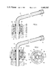
- FIG. 1 is a sectional view showing a sprinkler according to the invention
- FIG. 2 is a sectional view taken on line II-II in FIG. 1;
- FIG. 3 is a sectional view taken on line III-III in FIG. 1 and;
- FIG. 4 is a sectional view showing a modification of a sprinkler according to the invention.
- FIGS. 5 and 6 show another embodiment, FIG. 5 being a sectional view taken on line V-V in FIG. 6 and FIG. 6 a sectional view taken on line VI-VI in FIG. 5;
- FIG. 7 is a sectional view that is similar to FIGS. 1, 4 and 5 and shows a modification
- FIGS. 8 and 9 are sectional views showing another embodiment, FIG. 8 being a sectional view taken one line VIII-VIII of FIG. 9 and FIG. 9 being a sectional view taken on line IX-IX in FIG. 8;
- FIGS. 10 and 11 show a further embodiment, FIG. 10 being a longitudinal sectional view and FIG. 11 a sectional view taken on line XI-XI in FIG. 10;
- FIGS. 12 to 14 show another embodiment, FIG. 12 being a longitudinal sectional view and
- FIGS. 13 and 14 being sectional views taken on line XIII-XIII and XIV-XIV, respectively.
- FIG. 1 shows a stationary bearing member 1.
- the housing 2 of the braking device 3 is non-rotatably connected by pins 4 to the stationary bearing member.
- the housing 2 comprises a cover 5 and a body 6, which is connected by screw threads to the cover and interengages with the pins 4 for establishing a non-rotatable connection.
- the substantially cylindrical inside surface 7 of the housing cover 5 is formed with a groove 8, which receives extensions 9 of annular disks 10 so that the latter are non-rotatably connected to the inside surface 7 of the housing.
- Annular disks 13 spaced apart in the direction of the axis 11 of the spray pipe 12 are respectively disposed between adjacent annular disks 10.
- the annular disks 13 are non-rotatably coupled to the spray pipe 12 in that a bushing 14 rigidly connected to the spray pipe 12 is formed in its outside peripheral surface with a groove 15, which receives inwardly directed projections 16 of the disks 13.
- the mutually confronting end faces of adjacent annular disks 10 and 13 define gaps 17. These gaps as well as the entire interior cavity 18 of the housing are filled with a high-viscosity oil or paste. The width of the gap is limited by the inside end faces 19 and 20 of the body and cover of the housing, respectively.
- the embodiment shown in FIG. 4 comprises a housing 23, which can be swung open about a hinge extending along a generatrix of the shell of the housing.
- the housing 23 is non-rotatably connected to the bearing.
- the spray pipe 12 is non-rotatably connected directly to a radial extension consisting of a member which carries annular ribs 26. That member may be keyed to the spray pipe 12 or may be cemented to or shrunk on the outside surface of the spray pipe.
- the substantially cylindrical inside surface 27 of the housing 23 is provided with radially inwardly directed ribs 28 disposed in planes which are spaced along the axis of the spray pipe 12 so that gaps 29 are defined by cooperating adjacent extensions 26 and 28 and are filled with a high-viscosity oil or paste.
- the housing is protected by sealing rings 22 against an ingress of water and an escape of oil.
- FIGS. 5 and 6 differs from the embodiment shown in FIG. 4 in that three extensions, which are symmetrical with respect to the axis, are provided in each plane.
- the extensions 30 are non-rotatably connected to the spray pipe 12.
- the extensions 31 are non-rotatably connected to the body 32 of the housing.
- the housing comprises a cover 33 because this embodiment can be assembled in an axial direction if the arrangement shown in FIG. 5 is chosen, in which the extensions 30 non-rotatably connected to the spray pipe can be inserted between the peripheral spaces between the extensions 31 of the housing.
- the extensions 30 and 31 extending in axially spaced apart radial planes assume different angular positions so that the assembling operation comprises an insertion in an axial direction and a rotation of the extensions 30 which are non-rotatably connected to the spray pipe 12 so that they can be moved past the extensions 31 spaced apart in the axial direction.
- the body 32 of the housing is again non-rotatably connected to a stationary bearing member 34.
- a member 35 is non-rotatably connected to the spray pipe 12 and provided with radial ribs 36. These radial ribs 36 extend into the interior cavity 37 of a housing 38, which is connected to the bearing member 40 by an eccentric screw 39. Slit resilient ribs 42 are provided on the inside surface 41 of the housing 38 and protrude substantially radially inwardly. During a rotation of the member 35, the ribs 36 subject the high-viscosity fluid in the interior cavity 37 to a shear stress. The high-viscosity fluid cannot co-rotate because it adheres to the cylindrical inside surface 41 of the housing 38. This effect is improved by the resilient projections 42, which are non-rotatably connected to the housing and a slit and define chambers for the high-viscosity fluid so that the latter cannot rotate freely.
- the spray pipe 12 is also non-rotatably connected to e.g., shrunk on, a member 47, which carries radial extensions 43, 44, 45 and 46.
- the housing comprises also a cover 48 and a body 49, which is non-rotatably connected to the stationary bearing member 50.
- the inside surface of the housing is provided with inwardly protruding extensions 51, which are spaced between the axially spaced apart planes that contain the extensions 43, 44, 45 and 46, respectively.
- the radial extensions 51 of the housing are regularly spaced apart to define a uniform central angle ⁇ .
- the central angle ⁇ between the extensions 43 and 44 differs from the central angle ⁇ .
- the majority of the extensions non-rotatably connected to the spray pipe 12 ensure that at least one of the extensions 43, 44, 45, 46 registers with at least one extension 51 in a top plan view so that the high-viscosity fluid disposed between the stationary extensions and the extensions that are non-rotatably connected to the spray pipe is subjected to a shear stress.
- the spray pipe 12 is also non-rotatably connected to, e.g., shrunk on, a member 53 which carries radial extensions 52.
- the housing has also a cover 54 and a body 55, which is non-rotatably connected to the stationary bearing member 56.
- the inside surface 57 of the housing is not provided with inwardly protruding extensions.
- the interior cavity 57 of the housing is filled with a high-viscosity fluid, which is subjected to a shear stress by a rotation of the spray pipe 12 and of the extensions 52 so that the rotation is braked as desired.
- Suitable high-viscosity oils or pastes include mainly synthetic oils having a viscosity of 50 to 10,000 stokes, preferably about 2000 to 5000 stokes, at 20° C.
- FIGS. 12 to 14 show another embodiment of a sprinkler according to the invention.
- a radial extension 58 is non-rotatably connected to the spray pipe 12 and carries web 59, which extend in the direction of the axis 11 substantially throughout the axial length of the braking device 60.
- a stationary housing member 62 is connected to a bearing bracket 61 and has a radially extending part 63, which carries extensions or webs 64 that extend in the direction of the axis 11.
- the axial extensions 64 are spaced different distances from the axis 11 than the axial extensions 59 so that the axial extensions 59 and 64 will interdigitate during a rotation of the spray pipe 12.
- the housing 62 is again filled with a high-viscosity oil or paste.
- the axial extensions 59 and 64 spaced different distances from the axis 11 extend through the same central angle in the peripheral direction of the respective enveloping circles 65.
- This embodiment is much less susceptible to an ingress of water than a design having only radially extending extensions.
Landscapes
- Engineering & Computer Science (AREA)
- General Engineering & Computer Science (AREA)
- Mechanical Engineering (AREA)
- Nozzles (AREA)
Applications Claiming Priority (2)
| Application Number | Priority Date | Filing Date | Title |
|---|---|---|---|
| AT0579079A AT365478B (de) | 1979-08-30 | 1979-08-30 | Regner |
| AT5790/79 | 1979-08-30 |
Publications (1)
| Publication Number | Publication Date |
|---|---|
| US4440345A true US4440345A (en) | 1984-04-03 |
Family
ID=3579639
Family Applications (1)
| Application Number | Title | Priority Date | Filing Date |
|---|---|---|---|
| US06/179,483 Expired - Lifetime US4440345A (en) | 1979-08-30 | 1980-08-19 | Sprinkler |
Country Status (11)
| Country | Link |
|---|---|
| US (1) | US4440345A (de) |
| EP (1) | EP0025425B1 (de) |
| JP (2) | JPS5658554A (de) |
| AT (1) | AT365478B (de) |
| AU (1) | AU536429B2 (de) |
| DD (1) | DD152730A5 (de) |
| DE (1) | DE3063337D1 (de) |
| HU (1) | HU184320B (de) |
| IL (1) | IL60819A (de) |
| MX (1) | MX151369A (de) |
| YU (1) | YU207080A (de) |
Cited By (33)
| Publication number | Priority date | Publication date | Assignee | Title |
|---|---|---|---|---|
| US4660766A (en) * | 1985-09-18 | 1987-04-28 | Nelson Irrigation Corporation | Rotary sprinkler head |
| US4796811A (en) * | 1988-04-12 | 1989-01-10 | Nelson Irrigation Corporation | Sprinkler having a flow rate compensating slow speed rotary distributor |
| US4815662A (en) * | 1987-11-23 | 1989-03-28 | Hunter Edwin J | Stream propelled rotary stream sprinkler unit with damping means |
| US4886211A (en) * | 1987-05-13 | 1989-12-12 | Agroteam Consultants Ltd. 2 | Rotary sprinklers |
| US4932590A (en) * | 1989-08-07 | 1990-06-12 | Hunter Edwin J | Rotary stream sprinkler unit with rotor damping means |
| US4951877A (en) * | 1988-06-15 | 1990-08-28 | Interpump - S.P.A. | High-versatility device for cleaning surface by means of a liquid jet |
| US4971250A (en) * | 1989-08-07 | 1990-11-20 | Hunter Edwin J | Rotary stream sprinkler unit with rotor damping means |
| US5007586A (en) * | 1987-05-13 | 1991-04-16 | Agroteam Consultants Ltd | Rotary sprinklers |
| US5020556A (en) * | 1990-01-18 | 1991-06-04 | 501 Peerless Pump Company | Vehicle wash apparatus with spinning nozzles |
| US5058806A (en) * | 1990-01-16 | 1991-10-22 | Nelson Irrigation Corporation | Stream propelled rotary pop-up sprinkler with adjustable sprinkling pattern |
| USRE33823E (en) * | 1985-09-18 | 1992-02-18 | Nelson Irrigation Corporation | Rotary sprinkler head |
| US5288022A (en) * | 1991-11-08 | 1994-02-22 | Nelson Irrigation Corporation | Part circle rotator with improved nozzle assembly |
| US5377914A (en) * | 1993-02-03 | 1995-01-03 | Rain Bird Sprinkler Mfg., Corp. | Speed controlled rotating sprinkler |
| US5636558A (en) * | 1995-04-18 | 1997-06-10 | Kimberly-Clark Worldwide, Inc. | Method and apparatus for directing fluid |
| WO1999000195A1 (en) * | 1997-06-30 | 1999-01-07 | Interclean Equipment, Inc. | Spinning wash nozzle assembly |
| US6006637A (en) * | 1995-04-18 | 1999-12-28 | Kimberly-Clark Worldwide, Inc. | Servo driven watercutter |
| US6135364A (en) * | 1999-02-01 | 2000-10-24 | Nelson Irrigation Corporation | Rotator air management system |
| US6488401B1 (en) * | 1998-04-02 | 2002-12-03 | Anthony E. Seaman | Agitators for wave-making or mixing as for tanks, and pumps and filters |
| US6530532B1 (en) | 2000-02-05 | 2003-03-11 | Senninger Irrigation, Inc. | Kick-starter for sprinkler heads |
| WO2004085077A1 (en) | 2003-03-24 | 2004-10-07 | Plastro Irrigation A.C.S Ltd. | Revolving sprinkler |
| US20040195362A1 (en) * | 2003-04-02 | 2004-10-07 | Walker Samuel C. | Rotating stream sprinkler with torque balanced reaction drive |
| US6814304B2 (en) | 2002-12-04 | 2004-11-09 | Rain Bird Corporation | Rotating stream sprinkler with speed control brake |
| US20060006253A1 (en) * | 2004-07-07 | 2006-01-12 | Nelson Irrigation Corporation | Two-axis full-circle sprinkler with bent, rotating nozzle |
| US6991362B1 (en) | 1998-04-02 | 2006-01-31 | Seaman Anthony E | Agitators for wave-making or mixing as for tanks, and pumps and filters |
| US20060065759A1 (en) * | 2004-09-29 | 2006-03-30 | Olson Donald O | Sprinkler apparatus and related methods |
| US20060091232A1 (en) * | 2004-11-03 | 2006-05-04 | Grant Stuart F | Water deflection assembly |
| EP2113307A1 (de) * | 2008-04-29 | 2009-11-04 | Nelson Irrigation Corporation | Sprenkler mit viskosem Verzögerer und zugehöriges Verfahren |
| US9492832B2 (en) | 2013-03-14 | 2016-11-15 | Rain Bird Corporation | Sprinkler with brake assembly |
| US9587687B2 (en) | 2015-01-14 | 2017-03-07 | Nelson Irrigation Corporation | Viscous rotational speed control device |
| US9657790B2 (en) | 2015-01-14 | 2017-05-23 | Nelson Irrigation Corporation | Viscous rotational speed control device |
| US9700904B2 (en) | 2014-02-07 | 2017-07-11 | Rain Bird Corporation | Sprinkler |
| US10350619B2 (en) | 2013-02-08 | 2019-07-16 | Rain Bird Corporation | Rotary sprinkler |
| WO2020076445A1 (en) | 2018-10-12 | 2020-04-16 | Stoneage, Inc. | Viscous speed retarding device for rotary nozzles with internal piston for thermal expansion |
Families Citing this family (11)
| Publication number | Priority date | Publication date | Assignee | Title |
|---|---|---|---|---|
| FR2594945B1 (fr) * | 1986-02-21 | 1988-06-17 | Jaeger | Dispositif amortisseur et dispositif de mesure du niveau de carburant dans un reservoir de vehicule automobile, incorporant ce dispositif amortisseur |
| AU595461B2 (en) * | 1987-06-10 | 1990-03-29 | Sugatsune Industrial Co., Ltd | A multi-disc damper using viscous fluid |
| EP0442570A1 (de) * | 1990-02-14 | 1991-08-21 | VOLVO CAR SINT-TRUIDEN, naamloze vennootschap | Lenkungsdämpfer für Personenkraftwagen |
| FR2659407B1 (fr) * | 1990-03-09 | 1994-07-08 | Glaenzer Spicer Sa | Amortisseur rotatif a fluide visqueux. |
| FR2663705A2 (fr) * | 1990-03-09 | 1991-12-27 | Glaenzer Spicer Sa | Amortisseur rotatif. |
| IT1243136B (it) * | 1990-08-21 | 1994-05-24 | Arno Drechsel | Irrigatore rotante ad impatto |
| IL106138A (en) * | 1993-06-25 | 1997-03-18 | Dan Kibbutz Kibbutz Dan | Rotary sprinklers |
| JP3421484B2 (ja) * | 1995-09-01 | 2003-06-30 | 株式会社ニフコ | 回転ダンパー |
| US8567699B2 (en) * | 2009-08-05 | 2013-10-29 | Nelson Irrigation Corporation | Rotary strut sprinkler |
| CN103920606A (zh) * | 2013-12-14 | 2014-07-16 | 庞群 | 抗旱均匀淋浴器 |
| CN110252564B (zh) * | 2019-07-05 | 2024-02-13 | 农业农村部南京农业机械化研究所 | 一种喷杆减振稳定装置及控制方法 |
Citations (3)
| Publication number | Priority date | Publication date | Assignee | Title |
|---|---|---|---|---|
| US2473945A (en) * | 1946-07-05 | 1949-06-21 | Coppus Engineering Corp | Rotary fuel burner with removable fuel-conducting means |
| US2539778A (en) * | 1947-05-03 | 1951-01-30 | Gilbert & Barker Mfg Co | Rotary, internal-mixing, air-atomizing nozzle for oil burners |
| FR1321580A (fr) * | 1962-02-09 | 1963-03-22 | Perfectionnements aux asperseurs rotatifs |
Family Cites Families (3)
| Publication number | Priority date | Publication date | Assignee | Title |
|---|---|---|---|---|
| US3468485A (en) * | 1967-07-10 | 1969-09-23 | Western Brass Works | Sprinkler |
| US3598208A (en) * | 1969-06-25 | 1971-08-10 | Avco Corp | Liquid brake dynamometer |
| AT344435B (de) * | 1976-07-19 | 1978-07-25 | Brandl Dipl Ing Gerhard | Regner |
-
1979
- 1979-08-30 AT AT0579079A patent/AT365478B/de active
-
1980
- 1980-08-11 IL IL60819A patent/IL60819A/xx unknown
- 1980-08-15 YU YU02070/80A patent/YU207080A/xx unknown
- 1980-08-18 EP EP80890092A patent/EP0025425B1/de not_active Expired
- 1980-08-18 DE DE8080890092T patent/DE3063337D1/de not_active Expired
- 1980-08-19 US US06/179,483 patent/US4440345A/en not_active Expired - Lifetime
- 1980-08-25 DD DD80223483A patent/DD152730A5/de unknown
- 1980-08-29 MX MX183740A patent/MX151369A/es unknown
- 1980-08-29 JP JP11851280A patent/JPS5658554A/ja active Pending
- 1980-08-29 HU HU802119A patent/HU184320B/hu unknown
- 1980-08-29 AU AU61905/80A patent/AU536429B2/en not_active Ceased
-
1986
- 1986-05-30 JP JP1986081204U patent/JPS61204664U/ja active Pending
Patent Citations (3)
| Publication number | Priority date | Publication date | Assignee | Title |
|---|---|---|---|---|
| US2473945A (en) * | 1946-07-05 | 1949-06-21 | Coppus Engineering Corp | Rotary fuel burner with removable fuel-conducting means |
| US2539778A (en) * | 1947-05-03 | 1951-01-30 | Gilbert & Barker Mfg Co | Rotary, internal-mixing, air-atomizing nozzle for oil burners |
| FR1321580A (fr) * | 1962-02-09 | 1963-03-22 | Perfectionnements aux asperseurs rotatifs |
Cited By (49)
| Publication number | Priority date | Publication date | Assignee | Title |
|---|---|---|---|---|
| USRE33823E (en) * | 1985-09-18 | 1992-02-18 | Nelson Irrigation Corporation | Rotary sprinkler head |
| US4660766A (en) * | 1985-09-18 | 1987-04-28 | Nelson Irrigation Corporation | Rotary sprinkler head |
| US4886211A (en) * | 1987-05-13 | 1989-12-12 | Agroteam Consultants Ltd. 2 | Rotary sprinklers |
| US5007586A (en) * | 1987-05-13 | 1991-04-16 | Agroteam Consultants Ltd | Rotary sprinklers |
| US4815662A (en) * | 1987-11-23 | 1989-03-28 | Hunter Edwin J | Stream propelled rotary stream sprinkler unit with damping means |
| US4796811A (en) * | 1988-04-12 | 1989-01-10 | Nelson Irrigation Corporation | Sprinkler having a flow rate compensating slow speed rotary distributor |
| US4951877A (en) * | 1988-06-15 | 1990-08-28 | Interpump - S.P.A. | High-versatility device for cleaning surface by means of a liquid jet |
| US4932590A (en) * | 1989-08-07 | 1990-06-12 | Hunter Edwin J | Rotary stream sprinkler unit with rotor damping means |
| US4971250A (en) * | 1989-08-07 | 1990-11-20 | Hunter Edwin J | Rotary stream sprinkler unit with rotor damping means |
| US5058806A (en) * | 1990-01-16 | 1991-10-22 | Nelson Irrigation Corporation | Stream propelled rotary pop-up sprinkler with adjustable sprinkling pattern |
| US5020556A (en) * | 1990-01-18 | 1991-06-04 | 501 Peerless Pump Company | Vehicle wash apparatus with spinning nozzles |
| US5288022A (en) * | 1991-11-08 | 1994-02-22 | Nelson Irrigation Corporation | Part circle rotator with improved nozzle assembly |
| US5377914A (en) * | 1993-02-03 | 1995-01-03 | Rain Bird Sprinkler Mfg., Corp. | Speed controlled rotating sprinkler |
| US5636558A (en) * | 1995-04-18 | 1997-06-10 | Kimberly-Clark Worldwide, Inc. | Method and apparatus for directing fluid |
| US6101912A (en) * | 1995-04-18 | 2000-08-15 | Kimberly-Clark Worldwide, Inc. | Servo driven watercutter |
| US6006637A (en) * | 1995-04-18 | 1999-12-28 | Kimberly-Clark Worldwide, Inc. | Servo driven watercutter |
| WO1999000195A1 (en) * | 1997-06-30 | 1999-01-07 | Interclean Equipment, Inc. | Spinning wash nozzle assembly |
| EP0991476A1 (de) * | 1997-06-30 | 2000-04-12 | Interclean Equipment Inc. | Drehende waschdüse |
| US6209802B1 (en) * | 1997-06-30 | 2001-04-03 | Interclean Equipment, Inc. | Spinning wash nozzle assembly |
| EP0991476A4 (de) * | 1997-06-30 | 2004-08-18 | Interclean Equip Inc | Drehende waschdüse |
| US6488401B1 (en) * | 1998-04-02 | 2002-12-03 | Anthony E. Seaman | Agitators for wave-making or mixing as for tanks, and pumps and filters |
| US6655830B1 (en) * | 1998-04-02 | 2003-12-02 | Anthony E. Seaman | Agitators for wave-making or mixing as for tanks, and pumps and filters |
| US6991362B1 (en) | 1998-04-02 | 2006-01-31 | Seaman Anthony E | Agitators for wave-making or mixing as for tanks, and pumps and filters |
| US6135364A (en) * | 1999-02-01 | 2000-10-24 | Nelson Irrigation Corporation | Rotator air management system |
| US6530532B1 (en) | 2000-02-05 | 2003-03-11 | Senninger Irrigation, Inc. | Kick-starter for sprinkler heads |
| US7168634B2 (en) | 2002-12-04 | 2007-01-30 | Rain Bird Corporation | Debris resistant collar for rotating stream sprinklers |
| US6814304B2 (en) | 2002-12-04 | 2004-11-09 | Rain Bird Corporation | Rotating stream sprinkler with speed control brake |
| US20050082387A1 (en) * | 2002-12-04 | 2005-04-21 | Rain Bird Corporation | Debris resistant collar for rotating stream sprinklers |
| WO2004085077A1 (en) | 2003-03-24 | 2004-10-07 | Plastro Irrigation A.C.S Ltd. | Revolving sprinkler |
| US20040195362A1 (en) * | 2003-04-02 | 2004-10-07 | Walker Samuel C. | Rotating stream sprinkler with torque balanced reaction drive |
| US7299999B2 (en) | 2003-04-02 | 2007-11-27 | Rain Bird Corporation | Rotating stream sprinkler with torque balanced reaction drive |
| US20060006253A1 (en) * | 2004-07-07 | 2006-01-12 | Nelson Irrigation Corporation | Two-axis full-circle sprinkler with bent, rotating nozzle |
| US7143957B2 (en) | 2004-07-07 | 2006-12-05 | Nelson Irrigation Corporation | Two-axis full-circle sprinkler with bent, rotating nozzle |
| US20060065759A1 (en) * | 2004-09-29 | 2006-03-30 | Olson Donald O | Sprinkler apparatus and related methods |
| US7111796B2 (en) * | 2004-09-29 | 2006-09-26 | Olson Donald O | Sprinkler apparatus and related methods |
| US20060091232A1 (en) * | 2004-11-03 | 2006-05-04 | Grant Stuart F | Water deflection assembly |
| US7552877B2 (en) * | 2004-11-03 | 2009-06-30 | Nelson Irrigation Corporation | Water deflection assembly |
| EP2113307A1 (de) * | 2008-04-29 | 2009-11-04 | Nelson Irrigation Corporation | Sprenkler mit viskosem Verzögerer und zugehöriges Verfahren |
| US10350619B2 (en) | 2013-02-08 | 2019-07-16 | Rain Bird Corporation | Rotary sprinkler |
| US11084051B2 (en) | 2013-02-08 | 2021-08-10 | Rain Bird Corporation | Sprinkler with brake assembly |
| US9492832B2 (en) | 2013-03-14 | 2016-11-15 | Rain Bird Corporation | Sprinkler with brake assembly |
| US9700904B2 (en) | 2014-02-07 | 2017-07-11 | Rain Bird Corporation | Sprinkler |
| US10507476B2 (en) | 2014-02-07 | 2019-12-17 | Rain Bird Corporation | Sprinkler with brake assembly |
| US9587687B2 (en) | 2015-01-14 | 2017-03-07 | Nelson Irrigation Corporation | Viscous rotational speed control device |
| US9657790B2 (en) | 2015-01-14 | 2017-05-23 | Nelson Irrigation Corporation | Viscous rotational speed control device |
| US9995352B2 (en) | 2015-01-14 | 2018-06-12 | Nelson Irrigation Corporation | Viscous rotational speed control device |
| US10107342B2 (en) | 2015-01-14 | 2018-10-23 | Nelson Irrigation Corporation | Viscous rotational speed control device with fluid circuit |
| WO2020076445A1 (en) | 2018-10-12 | 2020-04-16 | Stoneage, Inc. | Viscous speed retarding device for rotary nozzles with internal piston for thermal expansion |
| EP3843905A4 (de) * | 2018-10-12 | 2021-11-24 | Stoneage, Inc. | Vorrichtung zur viskositätsgeschwindigkeitsverzögerung für rotationsdüsen mit innenkolben zur wärmeexpansion |
Also Published As
| Publication number | Publication date |
|---|---|
| HU184320B (en) | 1984-08-28 |
| AU536429B2 (en) | 1984-05-10 |
| IL60819A (en) | 1985-12-31 |
| YU207080A (en) | 1983-06-30 |
| ATA579079A (de) | 1980-10-15 |
| AU6190580A (en) | 1981-03-05 |
| DD152730A5 (de) | 1981-12-09 |
| IL60819A0 (en) | 1980-10-26 |
| DE3063337D1 (en) | 1983-07-07 |
| AT365478B (de) | 1982-01-25 |
| EP0025425A1 (de) | 1981-03-18 |
| MX151369A (es) | 1984-11-13 |
| JPS5658554A (en) | 1981-05-21 |
| EP0025425B1 (de) | 1983-05-18 |
| JPS61204664U (de) | 1986-12-23 |
Similar Documents
| Publication | Publication Date | Title |
|---|---|---|
| US4440345A (en) | Sprinkler | |
| CA2087304C (en) | Radial seal | |
| EP0329788B1 (de) | Dämpfer mit mehreren platten und der verwendung eines viskosen fluids | |
| JP2583319B2 (ja) | 軸パッキン | |
| US5074567A (en) | Modified one piece labyrinth seal | |
| SE509769C2 (sv) | Rotationsdämpare | |
| EP0183897B1 (de) | Radialwellendichtring | |
| US5392884A (en) | Slow-acting rotary device | |
| KR880701332A (ko) | 압축성 작동유체의 회전식 배출장치 | |
| KR950013933B1 (ko) | 유압제어장치 | |
| US3195902A (en) | Rotary seal with serpentine configurations | |
| US4396212A (en) | Rotary fluid coupling | |
| US3973782A (en) | Eccentricity compensating seal | |
| KR970021819A (ko) | 점성 유체 클러치 | |
| US5409241A (en) | Positive drive compensating shaft seal | |
| US4302019A (en) | Labyrinthine mechanical seal | |
| KR100502581B1 (ko) | 회전댐퍼 | |
| US2960356A (en) | Hydrodynamic rotary shaft seals | |
| DE4401567C1 (de) | Wellendichtung | |
| EP0207191B1 (de) | Kassettendichtung | |
| JP4107744B2 (ja) | 回転ダンパ | |
| KR970002870Y1 (ko) | 비스커스 커플링 | |
| KR960010017Y1 (ko) | 마찰판비스커스커플링 | |
| WO2021111345A1 (en) | A rotary damper of small size | |
| JP2526744Y2 (ja) | シールリング |
Legal Events
| Date | Code | Title | Description |
|---|---|---|---|
| AS | Assignment |
Owner name: OESTERREICHISCHE SALEN-KUNSTSTOFFWERK GESELLSCHAFT Free format text: ASSIGNMENT OF ASSIGNORS INTEREST.;ASSIGNORS:FIGWER, EDUARD;SCHMITZBERGER, FRANZ;REEL/FRAME:004029/0992 Effective date: 19800805 |
|
| STCF | Information on status: patent grant |
Free format text: PATENTED CASE |