EP0207191B1 - Kassettendichtung - Google Patents
Kassettendichtung Download PDFInfo
- Publication number
- EP0207191B1 EP0207191B1 EP85112839A EP85112839A EP0207191B1 EP 0207191 B1 EP0207191 B1 EP 0207191B1 EP 85112839 A EP85112839 A EP 85112839A EP 85112839 A EP85112839 A EP 85112839A EP 0207191 B1 EP0207191 B1 EP 0207191B1
- Authority
- EP
- European Patent Office
- Prior art keywords
- flange
- sleeve
- shaft
- cassette seal
- spindle
- Prior art date
- Legal status (The legal status is an assumption and is not a legal conclusion. Google has not performed a legal analysis and makes no representation as to the accuracy of the status listed.)
- Expired
Links
Images

Classifications
-
- F—MECHANICAL ENGINEERING; LIGHTING; HEATING; WEAPONS; BLASTING
- F16—ENGINEERING ELEMENTS AND UNITS; GENERAL MEASURES FOR PRODUCING AND MAINTAINING EFFECTIVE FUNCTIONING OF MACHINES OR INSTALLATIONS; THERMAL INSULATION IN GENERAL
- F16J—PISTONS; CYLINDERS; SEALINGS
- F16J15/00—Sealings
- F16J15/16—Sealings between relatively-moving surfaces
- F16J15/32—Sealings between relatively-moving surfaces with elastic sealings, e.g. O-rings
- F16J15/3248—Sealings between relatively-moving surfaces with elastic sealings, e.g. O-rings provided with casings or supports
- F16J15/3252—Sealings between relatively-moving surfaces with elastic sealings, e.g. O-rings provided with casings or supports with rigid casings or supports
- F16J15/3256—Sealings between relatively-moving surfaces with elastic sealings, e.g. O-rings provided with casings or supports with rigid casings or supports comprising two casing or support elements, one attached to each surface, e.g. cartridge or cassette seals
Definitions
- the invention relates to a cassette seal, consisting of an outer ring secured against rotation in the receiving bore with an inwardly facing hollow conical ring projection and an inner ring secured against rotation on the shaft or axis with two flanges axially encompassing the ring projection.
- DE-PS 33 25 201 refers to a cassette seal of the aforementioned type. At very low manufacturing costs, it is generally characterized by a sealing result while avoiding adjustment work before it is started up, even if radial displacements, axial displacements and / or angular displacements of the sealed shaft are to be expected. However, when used in mass production, there are occasional outliers in these properties, which is unsatisfactory.
- the invention has for its object to develop a cassette seal of the type mentioned in such a way that the occurrence of corresponding outliers is safely avoided without accepting other functional disadvantages.
- the cassette seal should be available at low cost.
- the cassette seal can be designed based on that according to DEPS 33 25 201.
- the flange which contacts the hollow-conical ring projection of the outer ring on the inside is always extended to form a sleeve, which in turn is supported on the surface, the sealed shaft or axis.
- the flange and the sleeve are connected in the area of their largest diameter.
- the sleeve and the flange can have essentially the same wall thickness, which results in a hermetically sealed cavity between the two points at which the surface of the sealed shaft or rod is touched by the resting inner ring. Its presence contributes significantly to achieving a good static seal in this area. Sealed medium, mostly oil, cannot pass through the cassette seal in the area of the surface of the sealed shaft or axis.
- the points of the inner ring bearing against the shaft or axis can be dimensioned very short in the axial direction and, if necessary, can be limited by intersecting conical surfaces without impairing good guidance of the inner ring. In terms of material, savings can be achieved in this way, which is why the cassette seal according to the invention does not easily have a noteworthy increase in price compared to one according to DE-PS 33 25 201.
- the sleeve can rest on an inwardly projecting annular surface of the outer ring on the side facing away from the annular projection of the flange.
- this area there is thus a further dynamic sealing zone which additionally supplements the series of dynamic sealing zones which already exist in this regard.
- the achievable sealing result shows a corresponding improvement.
- the outer ring of the cassette seal proposed according to the invention should consist of a material that is as strong as possible, and in addition to metallic materials, plastics can also be taken into consideration, in particular those with favorable sliding properties, such as PTFE.
- the inner ring is protected from mechanical damage by the outer ring. Considerations in this regard can therefore be taken into account when training the Inner ring are largely ignored.
- the focus of his training is on ensuring the pressure required in this area between the opposing parts.
- the use of rubber-elastic materials has increased. proven excellent.
- the flange contacting the hollow conical ring projection of the outer ring on the inside can be provided with recesses which are uniformly distributed on the circumference and open axially and radially outwards. This improves the dynamic sealing effect in this area, in particular if the flange faces the side of the medium to be sealed.
- the sleeve and the flange have a hollow cone and have an opposite direction of inclination. Both parts can be assigned to each other in mirror image.
- the externally visible parts of the outer ring essentially consist of a cap 2 made of sheet steel, into which the part carrying the ring projection 3 is inserted axially.
- the latter consists of PTFE or a related plastic.
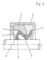
- the recess enclosed by the ring projection 3 is additionally closed by a cover 4 in the embodiment according to FIG. 3.
- the latter also consists of PTFE or a related material and is liquid-tight and secured against rotation on the part bearing in the annular projection 3 and thus on the cap 2.
- the inner rings used are made of rubber-elastic material with a Shore A and 65 hardness. They rest with the flange 5 under an elastic prestress on the inside of the ring projection 3, which is otherwise axially encompassed to form a further, dynamic sealing zone.
- the flange 5 merges smoothly into the sleeve 6 in the area of its largest outer diameter. which in turn is supported on the surface of the sealed shaft or axle.
- the cuff 6 is assigned to the inner ring in a mirror image, whereby a particularly good guiding effect is achieved.
- the sleeve is rolled in the area touching the surface of the sealed shaft or axis in the direction of the flange 5, whereby, in addition to good guidance, an improved flexibility of the inner ring is achieved.
- the inner ring has, in all versions, projections 7 which are distributed uniformly on the circumference and extend in the radial and axial directions.
- the annular space between the cap 2, the ring projection 3 and the inner ring in the embodiment according to FIG. 3 is filled with a lubricant, advantageously with colloidal graphite.
Landscapes
- Engineering & Computer Science (AREA)
- General Engineering & Computer Science (AREA)
- Mechanical Engineering (AREA)
- Sealing Devices (AREA)
- Gasket Seals (AREA)
- Semiconductor Lasers (AREA)
- Measurement Of Radiation (AREA)
- Encapsulation Of And Coatings For Semiconductor Or Solid State Devices (AREA)
- Sealing With Elastic Sealing Lips (AREA)
- Liquid Crystal (AREA)
Description
- Die Erfindung betrifft eine Kassettendichtung, bestehend aus einem verdrehsicher in der aufnehmenden Bohrung festgelegten Außenring mit einem nach innen weisenden, hohlkegeligen Ringvorsprung sowie einem verdrehsicher auf der Welle oder Achse festgelegten Innenring mit zwei den Ringvorsprung axial umgreifenden Flanschen.
- Auf eine Kassettendichtung der vorgenannten Art nimmt die DE-PS 33 25 201 Bezug. Sie zeichnet sich bei sehr geringen Herstellkosten im allgemeinen durch ein Abdichtungsergebnis unter Vermeidung von Justierarbeiten vor ihrer Inbetriebnahme auch dann aus, wenn Radialverlagerungen, Axialverlagerungen und/oder Winkelverlagerungen der abgedichteten Welle zu erwarten sind. Bei einer Verwendung in der Massenproduktion treten jedoch gelegentliche Ausreißer hinsichtlich dieser Eigenschaften auf, was wenig befriedigend ist.
- Der Erfindung liegt die Aufgabe zugrunde, eine Kassettendichtung der eingangs genannten Art derart weiter zu entwickeln, daß das Auftreten entsprechender Ausreißer ohne Inkaufnahme anderer funktioneller Nachteile sicher vermieden wird. Die Kassettendichtung soll kostengünstig verfügbar sein.
- Diese Aufgabe wird erfindungsgemäß bei einer Kassettendichtung der eingangs genannten Art dadurch gelöst, daß der den Ringvorsprung innenseitig berührende Flansch eine einstückig angeformte, in Richtung der Welle oder Achse vorspringende Manschette aufweist und daß die Manschette unter einer elastischen Vorspannung an der Welle oder Achse anliegt. Auf vorteilhafte Ausgestaltungen nehmen die Unteransprüche Bezug.
- Der Innenring der erfindungsgemäß vorgeschlagenen Kassettendichtung wird somit im Gegensatz zu demjenigen der Kassettendichtung gemäß DE-PS 33 25 201 an zwei einem erheblichen axialen Abstand aufweisenden Stellen durch die abgedichtete Welle oder Achse abgestützt. Er erhält hierdurch eine wesentlich verbesserte Führung, was offensichtlich von entscheidender Bedeutung ist im Hinblick auf die angestrebte Gemährleistbarkeit von guten Dichtungseigenschaften bei einer jeden eingebauten Einheit. Nachkontrollen sind entbehrlich.
- Hinsichtlich ihrer übrigen konstruktiven Merkmale kann die Kassettendichtung in Anlehnung an diejenige nach DEPS 33 25 201 ausgebildet werden. Der den hohlkegelig ausgebildeten Ringvorsprung des Außenringes innenseitig berührende Flansch ist jedoch stets zu einer Manschette verlängert, die ihrerseits auf der Oberfläche, der abgedichteten Welle oder Achse abgestützt ist.
- Im Hinblick auf die Erzielung einer möglichst guten Führung des Innenringes durch die abgedichtete Welle oder Achse hat es sich als vorteilhaft bewährt, wenn der Flansch und die Manschette im Bereich ihres größten Durchmessers verbunden sind. Die Manschette und der Flansch können dabei im wesentlichen dieselbe Wandstärke haben, wodurch sich zwischen den beiden Stellen, an denen die Oberfläche der abgedichteten Welle oder Stange von dem ruhend anliegenden Innenring berührt wird, ein hermetisch geschlossener Hohlraum ergibt. Sein Vorhandensein trägt wesentlich zur Erzielung einer guten statischen Abdichtung in diesem Bereich bei. Abgedichtetes Medium, zumeist handelt es sich um Öl, vermag dadurch die Kassettendichtung auch nicht im Bereich der Oberfläche der abgedichteten Welle oder Achse zu passieren. Die an der Welle oder Achse anliegenden Stellen des Innenringes können in achsialer Richtung sehr kurz bemessen und ohne Beeinträchtigung einer guten Führung des Innenringes gegebenenfalls durch einander durchschneidende Kegelflächen begrenzt werden. Werkstoffmäßig lassen sich hierdurch Einsparungen erzielen, weshalb die erfindungsgemäße Kassettendichtung gegenüber einer solchen nach der DE-PS 33 25 201 eine nennenwerte Verteuerung nicht ohne weiteres aufweist.
- Die Manschette kann nach einer vorteilhaften Ausgestaltung auf der von dem Ringvorsprung des Flansches abgewandten Seite an einer nach innen vorspringenden Kreisringfläche des Außenringes anliegen. In diesem Bereich ergibt sich somit eine weitere dynamische Abdichtungszone die die Serie der im übrigen diesbezüglich bereits vorhandenen, dynamischen Abdichtungszonen zusätzlich ergänzt. Das erzielbare Abdichtungsergebnis weist eine dementsprechende Verbesserung auf.
- In Anwendungsfällen, in denen mit starken radialen und/oder axialen Verlagerungen der abgedichteten Welle oder Achse zu rechnen ist, hat es sich als vorteilhaft bewährt, wenn die Manschette in dem die Achse oder Welle berührenden Bereich in Richtung des Flanschen eingerollt ist. Die elastische Verformbarkeit des Innenringes erfährt hierdurch eine deutliche Verbesserung, was dazu führt, daß sich die unter Betriebsbedingungen gleitend aneinander anliegende Flächen des Innen- und des Außenringes hinsichtlich ihrer gegenseitigen Zuordnung auch beim Auftreten von Winkelverlagerungen der Abgedichteten Welle oder Achse kaum verändern. Das ist von erheblichem Vorteil hinsichtlich der Erzielung eines guten Abdichtungsergebnisses auch beim Auftreten entsprechender Betriebssituationen.
- Der Außenring der erfindungsgemäß vorgeschlagenen Kassettendichtung soll aus einem möglichst festem Werkstoff bestehen, wobei neben metallischen Werkstoffen auch Kunststoffe in die Überlegungen mit einbezogen werden können, insbesondere solche mit günstigen Gleiteigenschaften, wie beispielsweise PTFE. Der Innenring wird durch den Außenring vor mechanischen Beschädigungen geschützt. Diesbezügliche Überlegungen können daher bei der Ausbildung des Innenringes weitgehend außer Acht gelassen werden. Im Mittelpunkt seiner Ausbildung steht neben der Erzielung möglichst geringer Reibungsverluste im Bereich der dynamischen Abdichtungszonen die Gewährleistung der in diesem Bereich erforderlichen Anpressung zwischen den einander gegenüberliegenden Teilen. Die Verwendung gummielastischer Werkstoffe hat sich. ausgezeichnet bewährt.
- Der den hohlkegeligen Ringvorsprung des Au- ßenringes innenseitig berührender Flansch kann im Bereich seines größten Durchmessers mit gleichmäßig auf dem Umfang verteilten, axial und radial nach außen geöffneten Aussparungen versehen sein. Die dynamische Abdichtwirkung in diesem Bereich wird hierdurch verbessert, insbesondere wenn der Flansch der Seite des abzudichtenden Mediums zugewandt ist.
- Hinsichtlich der Erzielung einer guten Führung des Innenringes hat es sich als vorteilhaft bewährt, wenn die Manschette und der Flansch hohlkegelig ausgebildet und eine entgegengesetzte Neigungsrichtung haben. Beide Teile können einander spiegelbildlich zugeordnet werden.
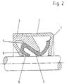
- Der Gegenstand der vorliegenden Erfindung wird nachfolgend anhand der in der Anlage beigefügten Zeichnung weiter erläutert. Diese zeigt drei verschiedene Ausführungen von Kassettendichtungen jeweils in halbeschnittener Darstellung. In allen Fällen ist der Außenring mehrteilig ausgebildet, wobei die einzelnen Teile flüssigkeitsdicht aneinander festgelet sind. Eine einteilige Ausführung ist aber selbstverständlich ebenfalls möglich.
- In allen drei Fällen bestehen die äußerlich sichtbaren Teile des Außenringes im wesentlichen aus einer Kappe 2 aus Stahlblech, in welche der den Ringvorsprung 3 tragende Teil axial eingefügt ist. Letzterer besteht aus PTFE oder einen artverwandten Kunststoff. Er weist dadurch besondere günstige Reibungseigenschaften auf, was sich als vorteilhaft bewährt hat im Hinblick auf die Erzielung einer möglichst langen Gebrauchsdauer. Die von dem Ringvorsprung 3 umschlossene Aussparung ist bei der Ausführung nach Figur 3 zusätzlich durch einen Deckel 4 verschlossen. Letzterer besteht ebenfalls aus PTFE oder einem artverwandten Werkstoff und ist flüssigkeitsdicht und verdrehsicher an dem in dem Ringvorsprung 3 tragenden Teil und damit an der Kappe 2 festgelegt.
- Die zur Anwendung gelangenden Innenringe bestehen aus gummielastischem Werkstoff einer Härte Shore A und 65. Sie liegen mit dem Flansch 5 unter einer elastischen Vorspannung an der Innenseite des Ringvorspungs 3 an, welcher im übrigen unter Bildung einer weiteren, dynamischen Abdichtungszone axial umgriffen wird. Der Flansch 5 geht im Bereich seines größten Außendurchmessers gleichmäßig in die Manschette 6 über. die ihrerseits auf der Oberfläche der abgedichteten Welle oder Achse abgestützt ist. Die Manschette 6 ist bei der Ausführung nach Figur 1 dem Innenring spiegelbildlich zugeordnet, wodurch eine besonders gute Führungswirkung erzielt wird. Bei den Ausführungen nach den Figuren 2 und 3 ist die Manschette in dem die Oberfläche der abgedichteten Welle oder Achse berührenden Bereich in Richtung des Flansches 5 eingerollt, wodurch neben einer guten Führung eine verbesserte Nachgiebigkeit des Innenringes erreicht wird.
- Dieser vermag durch gelegentlich auftretende Winkelverlagerungen der abgedichteten Welle oder Achse besser auszugleichen. Zusätzlich ergibt sich eine weitere dynamische Abdichtungszone 8, die dos insgesamt erzielte Abdichtungsergebnis verbessert.
- Der Innenring weist im Bereich seiner größten Durchmesser bei allen Ausführungen gleichmäßig auf dem Umfang verteilte, sich in radialer und axialer Richtung erstreckende Vorsprünge 7 auf.
- Diese üben auf auftreffende Flüssigkeit eine Förderwirkung aus, was das Abdichtungsergebnis begünstigt. Um gleichzeitig gute Notlaufeigenschaften zu gewährleisten, ist der ringförmige Raum zwischen der Kappe 2, dem Ringvorsprung 3 und dem Innenring bei der Ausführung nach Figur 3 mit einem Schmierstoff gefüllt, vorteilhaft mit kolloidalem Graphit.
Claims (7)
Priority Applications (1)
| Application Number | Priority Date | Filing Date | Title |
|---|---|---|---|
| AT85112839T ATE41987T1 (de) | 1985-06-04 | 1985-10-10 | Kassettendichtung. |
Applications Claiming Priority (2)
| Application Number | Priority Date | Filing Date | Title |
|---|---|---|---|
| DE3519966A DE3519966C1 (de) | 1985-06-04 | 1985-06-04 | Kassettendichtung |
| DE3519966 | 1985-06-04 |
Publications (3)
| Publication Number | Publication Date |
|---|---|
| EP0207191A2 EP0207191A2 (de) | 1987-01-07 |
| EP0207191A3 EP0207191A3 (en) | 1987-11-11 |
| EP0207191B1 true EP0207191B1 (de) | 1989-04-05 |
Family
ID=6272387
Family Applications (1)
| Application Number | Title | Priority Date | Filing Date |
|---|---|---|---|
| EP85112839A Expired EP0207191B1 (de) | 1985-06-04 | 1985-10-10 | Kassettendichtung |
Country Status (4)
| Country | Link |
|---|---|
| EP (1) | EP0207191B1 (de) |
| AT (1) | ATE41987T1 (de) |
| DE (2) | DE3519966C1 (de) |
| ES (1) | ES290349Y (de) |
Families Citing this family (2)
| Publication number | Priority date | Publication date | Assignee | Title |
|---|---|---|---|---|
| US7025357B2 (en) * | 2001-06-08 | 2006-04-11 | Freudenberg-Nok General Partnership | Shaft seal having lip supports |
| DE10312050A1 (de) * | 2003-03-18 | 2004-10-07 | Spicer Gelenkwellenbau Gmbh & Co. Kg | Abdichtanordnung für den Längenausgleich einer Kreuzgelenkwelle |
Family Cites Families (3)
| Publication number | Priority date | Publication date | Assignee | Title |
|---|---|---|---|---|
| DE3237638C2 (de) * | 1982-10-11 | 1984-09-20 | Fa. Carl Freudenberg, 6940 Weinheim | Wellendichtung |
| DE3320855C1 (de) * | 1983-06-09 | 1984-08-16 | Fa. Carl Freudenberg, 6940 Weinheim | Dichtung |
| DE3325201C1 (de) * | 1983-07-13 | 1984-05-24 | Fa. Carl Freudenberg, 6940 Weinheim | Dichtung |
-
1985
- 1985-06-04 DE DE3519966A patent/DE3519966C1/de not_active Expired
- 1985-10-10 AT AT85112839T patent/ATE41987T1/de not_active IP Right Cessation
- 1985-10-10 EP EP85112839A patent/EP0207191B1/de not_active Expired
- 1985-10-10 DE DE8585112839T patent/DE3569281D1/de not_active Expired
- 1985-11-15 ES ES1985290349U patent/ES290349Y/es not_active Expired
Also Published As
| Publication number | Publication date |
|---|---|
| DE3569281D1 (en) | 1989-05-11 |
| ATE41987T1 (de) | 1989-04-15 |
| ES290349Y (es) | 1987-01-16 |
| DE3519966C1 (de) | 1986-07-24 |
| EP0207191A3 (en) | 1987-11-11 |
| EP0207191A2 (de) | 1987-01-07 |
| ES290349U (es) | 1986-05-16 |
Similar Documents
| Publication | Publication Date | Title |
|---|---|---|
| EP0157904B1 (de) | Kassettendichtung | |
| EP0230503B1 (de) | Wellendichtung | |
| EP0133928B1 (de) | Radialwellendichtring | |
| EP0123724B1 (de) | Dichtung | |
| DE3204989C2 (de) | Kassettendichtung | |
| EP0135646B1 (de) | Gummikupplung | |
| EP0082239B1 (de) | Radialwellendichtring | |
| EP0980998A2 (de) | Radialwellendichtring | |
| EP1041318B1 (de) | Dichtring | |
| EP0362468A1 (de) | Wellendichtung | |
| EP0266479B1 (de) | Torsionsschwingungsdämpfer mit integriertem Schrumpfring | |
| EP0212041A1 (de) | Schwungrad | |
| EP1026428A2 (de) | Dichtring | |
| EP0798498B1 (de) | Radialwellendichtring mit drehrichtungsunabhängiger Förderwirkung | |
| EP0137092B1 (de) | Achs- oder Wellendichtung | |
| EP0156942B1 (de) | Dichtung | |
| EP0207191B1 (de) | Kassettendichtung | |
| EP0187891B1 (de) | Radialwellendichtring | |
| DE3501334C1 (de) | Dichtung | |
| EP0052689A1 (de) | Stangen- oder Kolbendichtung | |
| EP0086953B1 (de) | Wellendichtung | |
| DE3221526A1 (de) | Wellendichtring | |
| DE3320855C1 (de) | Dichtung | |
| DE102004020965B4 (de) | Radialwellendichtring | |
| EP0242431A2 (de) | Dichtring |
Legal Events
| Date | Code | Title | Description |
|---|---|---|---|
| PUAI | Public reference made under article 153(3) epc to a published international application that has entered the european phase |
Free format text: ORIGINAL CODE: 0009012 |
|
| AK | Designated contracting states |
Kind code of ref document: A2 Designated state(s): AT BE DE FR GB IT NL SE |
|
| PUAL | Search report despatched |
Free format text: ORIGINAL CODE: 0009013 |
|
| AK | Designated contracting states |
Kind code of ref document: A3 Designated state(s): AT BE DE FR GB IT NL SE |
|
| 17P | Request for examination filed |
Effective date: 19871015 |
|
| 17Q | First examination report despatched |
Effective date: 19880721 |
|
| ITF | It: translation for a ep patent filed | ||
| GRAA | (expected) grant |
Free format text: ORIGINAL CODE: 0009210 |
|
| AK | Designated contracting states |
Kind code of ref document: B1 Designated state(s): AT BE DE FR GB IT NL SE |
|
| REF | Corresponds to: |
Ref document number: 41987 Country of ref document: AT Date of ref document: 19890415 Kind code of ref document: T |
|
| GBT | Gb: translation of ep patent filed (gb section 77(6)(a)/1977) | ||
| REF | Corresponds to: |
Ref document number: 3569281 Country of ref document: DE Date of ref document: 19890511 |
|
| ET | Fr: translation filed | ||
| PLBE | No opposition filed within time limit |
Free format text: ORIGINAL CODE: 0009261 |
|
| STAA | Information on the status of an ep patent application or granted ep patent |
Free format text: STATUS: NO OPPOSITION FILED WITHIN TIME LIMIT |
|
| 26N | No opposition filed | ||
| ITTA | It: last paid annual fee | ||
| PGFP | Annual fee paid to national office [announced via postgrant information from national office to epo] |
Ref country code: GB Payment date: 19940922 Year of fee payment: 10 |
|
| PGFP | Annual fee paid to national office [announced via postgrant information from national office to epo] |
Ref country code: SE Payment date: 19940923 Year of fee payment: 10 |
|
| PGFP | Annual fee paid to national office [announced via postgrant information from national office to epo] |
Ref country code: DE Payment date: 19940928 Year of fee payment: 10 |
|
| PGFP | Annual fee paid to national office [announced via postgrant information from national office to epo] |
Ref country code: AT Payment date: 19941011 Year of fee payment: 10 |
|
| PGFP | Annual fee paid to national office [announced via postgrant information from national office to epo] |
Ref country code: FR Payment date: 19941013 Year of fee payment: 10 |
|
| PGFP | Annual fee paid to national office [announced via postgrant information from national office to epo] |
Ref country code: NL Payment date: 19941031 Year of fee payment: 10 |
|
| PGFP | Annual fee paid to national office [announced via postgrant information from national office to epo] |
Ref country code: BE Payment date: 19941108 Year of fee payment: 10 |
|
| EAL | Se: european patent in force in sweden |
Ref document number: 85112839.7 |
|
| PG25 | Lapsed in a contracting state [announced via postgrant information from national office to epo] |
Ref country code: DE Effective date: 19950314 |
|
| PG25 | Lapsed in a contracting state [announced via postgrant information from national office to epo] |
Ref country code: GB Effective date: 19951010 Ref country code: AT Effective date: 19951010 |
|
| PG25 | Lapsed in a contracting state [announced via postgrant information from national office to epo] |
Ref country code: SE Effective date: 19951011 |
|
| PG25 | Lapsed in a contracting state [announced via postgrant information from national office to epo] |
Ref country code: BE Effective date: 19951031 |
|
| BERE | Be: lapsed |
Owner name: FIRMA CARL FREUDENBERG Effective date: 19951031 |
|
| PG25 | Lapsed in a contracting state [announced via postgrant information from national office to epo] |
Ref country code: NL Effective date: 19960501 |
|
| GBPC | Gb: european patent ceased through non-payment of renewal fee |
Effective date: 19951010 |
|
| PG25 | Lapsed in a contracting state [announced via postgrant information from national office to epo] |
Ref country code: FR Effective date: 19960628 |
|
| EUG | Se: european patent has lapsed |
Ref document number: 85112839.7 |
|
| NLV4 | Nl: lapsed or anulled due to non-payment of the annual fee |
Effective date: 19960501 |
|
| REG | Reference to a national code |
Ref country code: FR Ref legal event code: ST |