US4398609A - Apparatus for sinking wells in the ground - Google Patents
Apparatus for sinking wells in the ground Download PDFInfo
- Publication number
- US4398609A US4398609A US06/357,580 US35758082A US4398609A US 4398609 A US4398609 A US 4398609A US 35758082 A US35758082 A US 35758082A US 4398609 A US4398609 A US 4398609A
- Authority
- US
- United States
- Prior art keywords
- rope
- tail piece
- ring
- passages
- resilient member
- Prior art date
- Legal status (The legal status is an assumption and is not a legal conclusion. Google has not performed a legal analysis and makes no representation as to the accuracy of the status listed.)
- Expired - Fee Related
Links
- 238000009527 percussion Methods 0.000 claims abstract description 11
- 229920006395 saturated elastomer Polymers 0.000 description 3
- 238000010276 construction Methods 0.000 description 2
- 238000000034 method Methods 0.000 description 1
- 238000003466 welding Methods 0.000 description 1
Images

Classifications
-
- E—FIXED CONSTRUCTIONS
- E21—EARTH OR ROCK DRILLING; MINING
- E21B—EARTH OR ROCK DRILLING; OBTAINING OIL, GAS, WATER, SOLUBLE OR MELTABLE MATERIALS OR A SLURRY OF MINERALS FROM WELLS
- E21B4/00—Drives for drilling, used in the borehole
- E21B4/06—Down-hole impacting means, e.g. hammers
-
- E—FIXED CONSTRUCTIONS
- E21—EARTH OR ROCK DRILLING; MINING
- E21B—EARTH OR ROCK DRILLING; OBTAINING OIL, GAS, WATER, SOLUBLE OR MELTABLE MATERIALS OR A SLURRY OF MINERALS FROM WELLS
- E21B7/00—Special methods or apparatus for drilling
- E21B7/26—Drilling without earth removal, e.g. with self-propelled burrowing devices
Definitions
- the present invention relates to construction plant and has specific reference to apparatus for sinking wells in the ground.
- the invention may be used to advantage at well sinking rigs, for example, in retrieving a tool with the aid of the means of extracting fastened to the tail piece and pulled by a winch.
- the main disadvantage of said apparatus is the breaking of the rope away at the weld under the impact loads arising during operation.
- the main object of the present invention is to enhance operational reliability of the apparatus as a whole.
- a further object of the invention is to extend the service life of the apparatus.
- Yet another object of the invention is to simplify the apparatus and shorten the period of adjustment thereof.
- the surface of the resilient member, that of the ring and the inside surface of the tail piece are taper-shaped.
- the rope can be provided with end-face passages having stops.
- the resilient member contained in the clearance between the tail piece of the percussion unit and the ring coaxially fitted into the tail piece, i.e. at the place of contact, serves to dampen the impact loads arising in the rope due to the action of the percussion unit.
- the ring ensures a reliable attachment of the resilient member to the tail piece.
- the passages in the body of the resilient member reeved wherethrough are the ends of the rope increase the area of the contact between the resilient member and the rope, contributing to a further reduction of the impact loads coming on the rope due to the percussion unit.
- the stops provided on the inside surface of the tail piece and in the end face of the ring give adequate support to the tail piece in contact with the percussion unit and transmit to the tail piece the effort applied to the means of extracting.
- the passages in the body of the tail piece and the ring and the taper-shaped surfaces of the resilient member and the ring in conjunction with the taper-shaped inside surface of tail piece cater for reliable fastening of the rope to the tail piece without slipping.
- the disclosed apparatus combines structural simplicity with reliability and durability, the service life thereof amounting to 500-600 running hours. Noteworthy is also the ease of taking the apparatus apart.
- FIG. I is a side elevation, partly cut away, of the apparatus for sinking wells in the ground according to the invention.
- FIG. 2 is a view of the framed portion I in FIG. I on an enlarged scale
- FIG. 3 is a view similar to FIG. 2 depicting another embodiment of the invention.
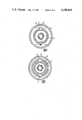
- FIG. 4 is a section on line IV-IV in FIG. 2;
- FIG. 5 is a section on line V-V in FIG. 2.
- the apparatus for sinking wells incorporates a percussion unit I in a tail piece 2 whereof there are fastened ends 4 of a rope 3.
- Said ends consist of sleeves slipped on the rope 3 and crimped under a press, and the fastening is effected by means of a ring 5 and a resilient member 6.
- Said member 6 is provided with passages 7 reeved wherethrough are the ends of the rope 3 connected at the inflection to a means of extracting 8.
- the inside surface of the tail piece 2 is provided with stops 9 having passages 10 also reeved wherethrough are the ends 4 of the rope 3.
- the surfaces II of the resilient member 6, the surfaces 12 of the ring 5 and the inside surface 13 of the tail piece 2 can be taper-shaped so as to prevent slipping of the rope.
- the ring 5 can be provided with an end-face stop 14 having passages 15 reeved wherethrough are the ends of the rope 3. (The rope 3 together with its ends 4 are not shown in the upper halves of FIGS. 2, 3, 4 and 5).
- the operating percussion unit On sinking the well to a specified depth (or driving the borehole to a specified length), the operating percussion unit is extracted from the ground by pulling at the rope 3, using a winch 8 or any other suitable means of extracting. Said procedure is unavoidable, especially in a weak water-saturated ground.
- the resilient member 6 prevents the impact loads set up in the parts when the percussion unit I is in operation from influencing the components effecting the joint between the rope and said unit, safeguarding said components from damage and extending the service life of the apparatus; the resulting stresses decrease and the reliability of the apparatus increases.
- the disclosed apparatus for sinking wells in the ground reduces the effect of the impact loads on the components of the fastening of the rope which is a factor predetermining the effectiveness of said apparatus in working backfilled and water-saturated grounds.
Landscapes
- Engineering & Computer Science (AREA)
- Life Sciences & Earth Sciences (AREA)
- Geology (AREA)
- Mining & Mineral Resources (AREA)
- Physics & Mathematics (AREA)
- Environmental & Geological Engineering (AREA)
- Fluid Mechanics (AREA)
- General Life Sciences & Earth Sciences (AREA)
- Geochemistry & Mineralogy (AREA)
- Mechanical Engineering (AREA)
- Earth Drilling (AREA)
Priority Applications (2)
| Application Number | Priority Date | Filing Date | Title |
|---|---|---|---|
| DE3207294A DE3207294C2 (de) | 1982-03-01 | 1982-03-01 | Einrichtung zur Niederbringung von Bohrlöchern in das Erdreich |
| US06/357,580 US4398609A (en) | 1982-03-01 | 1982-03-12 | Apparatus for sinking wells in the ground |
Applications Claiming Priority (2)
| Application Number | Priority Date | Filing Date | Title |
|---|---|---|---|
| DE3207294A DE3207294C2 (de) | 1982-03-01 | 1982-03-01 | Einrichtung zur Niederbringung von Bohrlöchern in das Erdreich |
| US06/357,580 US4398609A (en) | 1982-03-01 | 1982-03-12 | Apparatus for sinking wells in the ground |
Publications (1)
| Publication Number | Publication Date |
|---|---|
| US4398609A true US4398609A (en) | 1983-08-16 |
Family
ID=25799947
Family Applications (1)
| Application Number | Title | Priority Date | Filing Date |
|---|---|---|---|
| US06/357,580 Expired - Fee Related US4398609A (en) | 1982-03-01 | 1982-03-12 | Apparatus for sinking wells in the ground |
Country Status (2)
| Country | Link |
|---|---|
| US (1) | US4398609A (de) |
| DE (1) | DE3207294C2 (de) |
Citations (4)
| Publication number | Priority date | Publication date | Assignee | Title |
|---|---|---|---|---|
| US1403766A (en) * | 1916-10-18 | 1922-01-17 | John S Gillies | Apparatus for making concrete piles |
| US3550698A (en) * | 1968-07-25 | 1970-12-29 | Ingersoll Rand Co | Penetration method and apparatus |
| US4171727A (en) * | 1976-10-22 | 1979-10-23 | Institut Gornogo Dela Sibirskogo Otdelenia Akademii Nauk S S S R | Reversible, percussive device for ground perforation |
| US4295533A (en) * | 1979-03-26 | 1981-10-20 | Paul Schmidt | Pneumatically operated ram borer |
Family Cites Families (5)
| Publication number | Priority date | Publication date | Assignee | Title |
|---|---|---|---|---|
| US1041501A (en) * | 1911-04-11 | 1912-10-15 | Mark W Marsden | Apparatus for cleaning oil-wells. |
| US1406768A (en) * | 1919-03-13 | 1922-02-14 | Robert O Slater | Wire-line socket |
| GB177578A (en) * | 1920-12-01 | 1922-04-03 | Edgar Eugene Greve | An improved rope socket or swivel jar for use in connection with well drilling tools or apparatus |
| US1429312A (en) * | 1921-03-22 | 1922-09-19 | Augenstein Cecil Vernon | Wire-line socket |
| GB201807A (en) * | 1922-09-27 | 1923-08-09 | Paul Arbon | Improvements in apparatus for drilling wells |
-
1982
- 1982-03-01 DE DE3207294A patent/DE3207294C2/de not_active Expired
- 1982-03-12 US US06/357,580 patent/US4398609A/en not_active Expired - Fee Related
Patent Citations (4)
| Publication number | Priority date | Publication date | Assignee | Title |
|---|---|---|---|---|
| US1403766A (en) * | 1916-10-18 | 1922-01-17 | John S Gillies | Apparatus for making concrete piles |
| US3550698A (en) * | 1968-07-25 | 1970-12-29 | Ingersoll Rand Co | Penetration method and apparatus |
| US4171727A (en) * | 1976-10-22 | 1979-10-23 | Institut Gornogo Dela Sibirskogo Otdelenia Akademii Nauk S S S R | Reversible, percussive device for ground perforation |
| US4295533A (en) * | 1979-03-26 | 1981-10-20 | Paul Schmidt | Pneumatically operated ram borer |
Also Published As
| Publication number | Publication date |
|---|---|
| DE3207294A1 (de) | 1983-09-22 |
| DE3207294C2 (de) | 1984-04-26 |
Similar Documents
| Publication | Publication Date | Title |
|---|---|---|
| CA2285008C (en) | Electrically actuated disconnect apparatus | |
| CA2206169A1 (en) | A bit retention device for a bit and chuck assembly of a down-the-hole percussive drill | |
| ZA853820B (en) | A hydraulically operated percussive machine and an accumulator therefor | |
| WO1993003958A3 (en) | Anchor, anchorfluke and methods for anchoring | |
| US4446930A (en) | Drill steel removal attachment for rock drilling machine | |
| US4398609A (en) | Apparatus for sinking wells in the ground | |
| EP0094403B1 (de) | Felsenbrechanlage | |
| US4051685A (en) | Positioning method and apparatus for submersible pile driving | |
| GB2116226A (en) | Apparatus for sinking wells in the ground | |
| EP0286373A3 (de) | Ring zur Sicherung des Bohrmeissels bei der Bergung von Bohrgestängeteilen | |
| US5605192A (en) | Means and method to displace a logging tool to the bottom of a well for withdrawal through the well | |
| US2984881A (en) | Cable anchoring device | |
| CN209818058U (zh) | 一种用于无线传输装置脉冲发生器的供电走线装置 | |
| EP0778392A2 (de) | Verfahren und Vorrichtung zum Entfernen des obersten Teils einer Konstruktion im Meeresboden | |
| US2123783A (en) | Connecting device | |
| RU2001255C1 (ru) | Вставной забойный пульсатор | |
| SU1062370A1 (ru) | Разъединительное устройство бурильной колонны | |
| ATE275236T1 (de) | Flexible sinkgewichtanordnung | |
| SU1452970A2 (ru) | Устройство дл соединени магистрали сжатого воздуха с буровой штангой | |
| CA1194858A (en) | Recovery of ground drilling equipment | |
| CN211008551U (zh) | 一种用于防止测井仪器落井的测试堵头 | |
| WO2001092679A1 (en) | Device for raise boring | |
| GB1601929A (en) | Wellhead guide line and guide post assembly | |
| SU899922A1 (ru) | Устройство дл присоединени т говой цепи к исполнительному органу | |
| SU832069A1 (ru) | Устройство дл спуска потайныхОбСАдНыХ КОлОНН |
Legal Events
| Date | Code | Title | Description |
|---|---|---|---|
| AS | Assignment |
Owner name: INSTITUT GORNOGO DELA SIBIRSKOGO OTDELENIA AKADEMI Free format text: ASSIGNMENT OF ASSIGNORS INTEREST.;ASSIGNORS:KARAVAEV, ANDRON T.;PLAVSKIKH, VLADIMIR D.;TERSKOV, ALEXEI D.;AND OTHERS;REEL/FRAME:004126/0207 Effective date: 19830317 |
|
| MAFP | Maintenance fee payment |
Free format text: PAYMENT OF MAINTENANCE FEE, 4TH YEAR, PL 96-517 (ORIGINAL EVENT CODE: M170); ENTITY STATUS OF PATENT OWNER: LARGE ENTITY Year of fee payment: 4 |
|
| FEPP | Fee payment procedure |
Free format text: PAYOR NUMBER ASSIGNED (ORIGINAL EVENT CODE: ASPN); ENTITY STATUS OF PATENT OWNER: LARGE ENTITY |
|
| FEPP | Fee payment procedure |
Free format text: MAINTENANCE FEE REMINDER MAILED (ORIGINAL EVENT CODE: REM.); ENTITY STATUS OF PATENT OWNER: LARGE ENTITY |
|
| LAPS | Lapse for failure to pay maintenance fees | ||
| STCH | Information on status: patent discontinuation |
Free format text: PATENT EXPIRED DUE TO NONPAYMENT OF MAINTENANCE FEES UNDER 37 CFR 1.362 |
|
| FP | Lapsed due to failure to pay maintenance fee |
Effective date: 19910818 |