US4337216A - Device in an evaporative cooler - Google Patents
Device in an evaporative cooler Download PDFInfo
- Publication number
- US4337216A US4337216A US06/114,199 US11419980A US4337216A US 4337216 A US4337216 A US 4337216A US 11419980 A US11419980 A US 11419980A US 4337216 A US4337216 A US 4337216A
- Authority
- US
- United States
- Prior art keywords
- contact body
- water
- layers
- channels
- openings
- Prior art date
- Legal status (The legal status is an assumption and is not a legal conclusion. Google has not performed a legal analysis and makes no representation as to the accuracy of the status listed.)
- Expired - Lifetime
Links
- XLYOFNOQVPJJNP-UHFFFAOYSA-N water Substances O XLYOFNOQVPJJNP-UHFFFAOYSA-N 0.000 claims abstract description 59
- 210000002105 tongue Anatomy 0.000 claims description 6
- 230000000306 recurrent effect Effects 0.000 claims description 2
- 239000003595 mist Substances 0.000 abstract description 7
- 230000015572 biosynthetic process Effects 0.000 abstract description 4
- 238000001816 cooling Methods 0.000 description 14
- 238000009826 distribution Methods 0.000 description 7
- 238000007789 sealing Methods 0.000 description 5
- 238000004519 manufacturing process Methods 0.000 description 3
- 239000000463 material Substances 0.000 description 2
- 239000000203 mixture Substances 0.000 description 2
- 230000007704 transition Effects 0.000 description 2
- 230000005494 condensation Effects 0.000 description 1
- 238000009833 condensation Methods 0.000 description 1
- 239000000498 cooling water Substances 0.000 description 1
- 230000000694 effects Effects 0.000 description 1
- 238000010438 heat treatment Methods 0.000 description 1
- 238000012423 maintenance Methods 0.000 description 1
- 238000000034 method Methods 0.000 description 1
- 230000000149 penetrating effect Effects 0.000 description 1
- 239000002244 precipitate Substances 0.000 description 1
- 238000003825 pressing Methods 0.000 description 1
- 230000000644 propagated effect Effects 0.000 description 1
- 229920006395 saturated elastomer Polymers 0.000 description 1
- 238000007666 vacuum forming Methods 0.000 description 1
Images


Classifications
-
- F—MECHANICAL ENGINEERING; LIGHTING; HEATING; WEAPONS; BLASTING
- F28—HEAT EXCHANGE IN GENERAL
- F28F—DETAILS OF HEAT-EXCHANGE AND HEAT-TRANSFER APPARATUS, OF GENERAL APPLICATION
- F28F25/00—Component parts of trickle coolers
- F28F25/02—Component parts of trickle coolers for distributing, circulating, and accumulating liquid
-
- B—PERFORMING OPERATIONS; TRANSPORTING
- B01—PHYSICAL OR CHEMICAL PROCESSES OR APPARATUS IN GENERAL
- B01L—CHEMICAL OR PHYSICAL LABORATORY APPARATUS FOR GENERAL USE
- B01L9/00—Supporting devices; Holding devices
- B01L9/56—Means for indicating position of a recipient or sample in an array
-
- F—MECHANICAL ENGINEERING; LIGHTING; HEATING; WEAPONS; BLASTING
- F28—HEAT EXCHANGE IN GENERAL
- F28C—HEAT-EXCHANGE APPARATUS, NOT PROVIDED FOR IN ANOTHER SUBCLASS, IN WHICH THE HEAT-EXCHANGE MEDIA COME INTO DIRECT CONTACT WITHOUT CHEMICAL INTERACTION
- F28C1/00—Direct-contact trickle coolers, e.g. cooling towers
- F28C1/04—Direct-contact trickle coolers, e.g. cooling towers with cross-current only
-
- F—MECHANICAL ENGINEERING; LIGHTING; HEATING; WEAPONS; BLASTING
- F28—HEAT EXCHANGE IN GENERAL
- F28C—HEAT-EXCHANGE APPARATUS, NOT PROVIDED FOR IN ANOTHER SUBCLASS, IN WHICH THE HEAT-EXCHANGE MEDIA COME INTO DIRECT CONTACT WITHOUT CHEMICAL INTERACTION
- F28C1/00—Direct-contact trickle coolers, e.g. cooling towers
- F28C1/14—Direct-contact trickle coolers, e.g. cooling towers comprising also a non-direct contact heat exchange
- F28C2001/145—Direct-contact trickle coolers, e.g. cooling towers comprising also a non-direct contact heat exchange with arrangements of adjacent wet and dry passages
-
- Y—GENERAL TAGGING OF NEW TECHNOLOGICAL DEVELOPMENTS; GENERAL TAGGING OF CROSS-SECTIONAL TECHNOLOGIES SPANNING OVER SEVERAL SECTIONS OF THE IPC; TECHNICAL SUBJECTS COVERED BY FORMER USPC CROSS-REFERENCE ART COLLECTIONS [XRACs] AND DIGESTS
- Y02—TECHNOLOGIES OR APPLICATIONS FOR MITIGATION OR ADAPTATION AGAINST CLIMATE CHANGE
- Y02B—CLIMATE CHANGE MITIGATION TECHNOLOGIES RELATED TO BUILDINGS, e.g. HOUSING, HOUSE APPLIANCES OR RELATED END-USER APPLICATIONS
- Y02B30/00—Energy efficient heating, ventilation or air conditioning [HVAC]
- Y02B30/70—Efficient control or regulation technologies, e.g. for control of refrigerant flow, motor or heating
-
- Y—GENERAL TAGGING OF NEW TECHNOLOGICAL DEVELOPMENTS; GENERAL TAGGING OF CROSS-SECTIONAL TECHNOLOGIES SPANNING OVER SEVERAL SECTIONS OF THE IPC; TECHNICAL SUBJECTS COVERED BY FORMER USPC CROSS-REFERENCE ART COLLECTIONS [XRACs] AND DIGESTS
- Y10—TECHNICAL SUBJECTS COVERED BY FORMER USPC
- Y10S—TECHNICAL SUBJECTS COVERED BY FORMER USPC CROSS-REFERENCE ART COLLECTIONS [XRACs] AND DIGESTS
- Y10S165/00—Heat exchange
- Y10S165/90—Cooling towers
-
- Y—GENERAL TAGGING OF NEW TECHNOLOGICAL DEVELOPMENTS; GENERAL TAGGING OF CROSS-SECTIONAL TECHNOLOGIES SPANNING OVER SEVERAL SECTIONS OF THE IPC; TECHNICAL SUBJECTS COVERED BY FORMER USPC CROSS-REFERENCE ART COLLECTIONS [XRACs] AND DIGESTS
- Y10—TECHNICAL SUBJECTS COVERED BY FORMER USPC
- Y10S—TECHNICAL SUBJECTS COVERED BY FORMER USPC CROSS-REFERENCE ART COLLECTIONS [XRACs] AND DIGESTS
- Y10S261/00—Gas and liquid contact apparatus
- Y10S261/11—Cooling towers
-
- Y—GENERAL TAGGING OF NEW TECHNOLOGICAL DEVELOPMENTS; GENERAL TAGGING OF CROSS-SECTIONAL TECHNOLOGIES SPANNING OVER SEVERAL SECTIONS OF THE IPC; TECHNICAL SUBJECTS COVERED BY FORMER USPC CROSS-REFERENCE ART COLLECTIONS [XRACs] AND DIGESTS
- Y10—TECHNICAL SUBJECTS COVERED BY FORMER USPC
- Y10S—TECHNICAL SUBJECTS COVERED BY FORMER USPC CROSS-REFERENCE ART COLLECTIONS [XRACs] AND DIGESTS
- Y10S261/00—Gas and liquid contact apparatus
- Y10S261/77—Plume abatement
Definitions
- the present invention relates to a device in an evaporative cooler, such as a cooling tower, which comprises at least one contact body of the multi-layer type housed in a casing and having gaps existing between the layers through which air and water are passed in countercurrent relation.
- one main object of the present invention is to provide a simple and effective device in evaporative coolers for subdividing the contact body into dry and wet channels.
- Another object of the invention is to provide a simple water supply to the wet channels of the compact body.
- a further object of the invention is to provide a device by which overflow of water from the wet to the dry channels is prevented.
- a still further object of the present invention is to provide means preventing splashing from the wet channels to be propagated into the dry heated air.
- a conventional drop eliminator cannot be operated in the air mixture, but should much impair the result, since it should act as a moistener to the air leaving the dry channels.
- FIG. 1 shows a vertical section through an evaporative cooler, such as a cooling tower of the cross-current type, to which the invention has been applied.
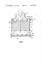
- FIG. 2 shows a similar section as presented in FIG. 1 through a cooling tower of the counter-current type.
- FIG. 3 is a perspective view of the top part of a contact body for the cooler of FIG. 1.
- FIG. 4 is a perspective view of the top part of a contact body for the cooler of FIG. 2.
- FIG. 5 is a side view of vertical jointing of two contact bodies
- FIG. 5a shows a section following the line A--A in FIG. 5.
- FIG. 6 is a top view of a portion of lateral jointing of two contact bodies, the left-hand part of FIG. 6 corresponding to the view B--B in FIG. 5.
- FIG. 7 shows a view similar to FIG. 6 of the contact bodies when brought together.
- the cooling tower shown in FIG. 1 comprises a casing 12 which houses several contact bodies 10 each of which is composed of layers or sheets 52, 54 (see also FIG. 3) which are disposed in parallel so as to form between them vertical gaps or channels.
- the layers are all corrugated with the corrugations crossing one another in every second layer, as is indicated with dashed lines in the upper part of the contact body 10. All corrugations extend with an angle to the vertical line and bear against one another at the pointwise distributed places of contact.
- This structure is known from e.g. the U.S. Pat. Nos. 3,682,747 and 3,415,502.
- the layers may be of plastic or other material which is scarcely permeable to water.
- the casing 12 is at opposite sides formed with lateral openings 14 for atmospheric air which enters in the direction of the arrow 16.
- the casing 12 has at its top a discharge opening 18 within which is provided an impeller 20 which is driven by a motor 22.
- the atmospheric air sucked in through the lateral openings 14 will thus be caused by the impeller 20 to flow in a mainly vertical direction upwards after the passage through the contact bodies 10 as indicated by the arrows 24.
- water distributing systems Positioned above the contact bodies 10 are water distributing systems which comprise a main 26 and branch pipes 28 and 30, which are equipped with valves 32, 34 for control or stopping of the water supply.
- the branch pipe 30 opens into a trough 36 positioned above the contact body 10 and having a perforated bottom for downward flow of the water into the contact body.
- the other branch pipe 28 is divided into further branches, of which two, denoted 38, 40, are shown in the drawing. These two branch pipes open into distributor pipes 42, 44 mounted horizontally in the top face of the contact
- the cooled water which has passed through the contact bodies 10 is collected in a sump 46 at the bottom of the cooling tower and is discharged through a pipe 48 controlled by a valve 50 to the place of utilization.
- a pipe 48 controlled by a valve 50 to the place of utilization.
- the water is returned through the main 26 to the cooling tower to be supplied to the contact bodies 10, the water then flowing in downward direction through the gaps and there meeting the upwards advancing air, the water thereby being cooled and the air taking up moisture until saturation.
- the contact body in FIG. 3 consists, as described above, of corrugated layers 52, 54 which are disposed in parallel so that between them vertical gaps or channels are formed.
- the layers which are manufactured by vacuum forming or pressing, for example, are formed, according to the invention with widened portion 52a or 54a, respectively, which portions are recurrent with even spacing and interconnected by an intermediate portion 53.
- these widened portions 52a, 54a, 53 will together form a box-shaped, funnel-like mouth which is open downwards towards the gaps or the channels existing between the layers.
- the widened portions 52a, 54a projecting in opposite directions from the centre line of each of the layers concerned will thus constitute alternately the long side walls of box-shaped funnel openings to adjacent gaps in the contact body.
- the contact body 10 will be subdivided at its top into several groups of openings, in the shown embodiment two groups, which optionally can be supplied with water or be kept dry.
- each box-shaped funnel adjacent each other in the transverse direction of the contact body, which implies that water will be poured into each second gap in the contact body, while gaps positioned therebetween will be kept dry.
- a plurality of pipes 42, 44 are arranged, their number in the shown example being two.
- At least the upper portion of the body may have corrugations with a minor angle to the horizontal plane, as is disclosed in the co-pending U.S. Patent Application Ser. No. 944,246 filed Sept. 21, 1978 concurrently herewith.
- the upper contact body 10 and the lower contact body 10a in FIG. 1 have a specific shape at the surfaces facing one another, which shape is shown in FIGS. 5 and 5a.
- the layers in the upper contact body will in the manufacturing process at the bottom side also be formed with widened portions in a manner similar to that at the top side, the widened portions at the bottom side being devised when the layers are joined together to form the contact body to define a socket 56 which has connection with those gaps or channels which on the top side of the contact body are supplied with water through the distribution pipes 42, 44.
- the layers of the lower contact body 10a are in the manufacturing process also formed with widened portions in the manner which has been described above, which widening portions in the assembling operation form a socket 58 which, however, has greater length and width than the socket 56.
- the arrangement is such that the sockets 56 protrude down into the sockets 58, which also have connection with every second channel or gap in the lower contact body 10a. In this way, there is ensured a transfer of water from the upper contact body 10 to the lower body 10a in every second passageway only without any water being capable of migrating over into the dry channels or gaps.
- the lateral faces of the contact bodies also have a specific shape which is shown in FIGS. 6 and 7.
- the left-hand part of FIG. 6 corresponds here to the lateral edge 60 of the contact body 10 in FIG. 5 viewed along the line B--B, whereas the right-hand part of FIG. 6 constitutes the reversed lateral edge 62 of an adjacent package.
- every second layer of the contact body 10 is longer and every second one shorter in the fill so that a zigzag-shaped edge face is formed.
- the tongues 64 thus formed in every second layer 10 will project into the gap 66 formed between the tongues of the opposed package.
- the edges 68 of the layers 10 are shaped, e.g. planed, to make good contact with one another.
- the main object with this jointing is to keep the moist and the dry air separated from each other at the transition from one package or body 10 to the next following package or body 10. This is rendered possible by the fact that the pressure drop always is the same in the dry as well as in the wet channels, for which reason no tendency exists in the air to pass from one gap or channel into another. Therefore, the shown jointing with abutment of the edges 68 is sufficient to maintain the subdivision between dry and wet channels at a transition from one package 10 to the next one.
- the body is shaped so that the corrugations and the gaps formed by them at the edge sides of the body 10 run obliquely upwards so as to form drop separators, or so-called eliminators 11 (FIGS. 1 and 5), which trap the water to cause it to flow back towards the interior of the contact body.
- eliminators 11 FGS. 1 and 5
- the gaps then direct the air downwards at the intake side and upwards at the discharge side so that the air forces the water back into the interior of the body 10 or prevents the discharged air from entraining water from the interior of the contact body.
- each of the opposed edge portions may have, as is shown in FIGS. 6 and 7 for the upper layers, over its entire length a sealing flange 70 which is bent out in opposite directions so that a broader sealing surface is formed along the entire length of the edge. This is especially suitable when the sheets of material forming the layers of the contact body 10 are thin.
- the invention is illustrated applied to a cooling tower of the counter-current type which comprises a casing 72 housing contact bodies 74 built up in the same manner as the contact bodies 10, which manner has been described in connection with FIG. 1.
- a cooling tower of the counter-current type which comprises a casing 72 housing contact bodies 74 built up in the same manner as the contact bodies 10, which manner has been described in connection with FIG. 1.
- an impeller member 78 With driving motor 80 located in an opening 82.
- the sucked-in air which is marked by the arrows 84, is blown out after the passage through the bodies 74 into the opening 82 as is indicated by the arrow 36.
- water distributing systems comprising a main 88 and two branch pipes the water supply to which is controlled by valves 94, 96.
- the branch pipe 90 is positioned above the packages 74 and equipped with sprayers 98 which distribute the water over the entire top face of the packages or contact bodies 74 when water is supplied to the pipe 90.
- the other branch pipe 92 is in connection with branch pipes 100 which open into distribution pipes 102 mounted horizontally in the top faces of the contact bodies 74 and described in more detail with reference to FIG. 4.
- the cooled water which has passed through the bodies 74 is collected in a sump 104 at the bottom of the tower and is discharged through a pipe 106 controlled by a valve 108 to the place of utilization.
- the cooling tower has two fills or bodies 74 located side by side.
- the bodies 74 are at their facing sides attached to a sealing wall 110 which prevents water from penetrating around the corners of the layers into the dry channels.
- This kind of sealing is rendered possible by the fact that air and water in counter-current mainly flow vertically through the packages and not laterally (unless where caused by the inclination of the channels).
- any jointing in lateral direction is not required and normally neither in vertical direction, since the overall height of counter-current towers normally is 1500 mms at the utmost.
- a vertical jointing can be made in the manner shown in FIGS. 5 and 5a.
- the contact body 74 presented in more detail in FIG. 4, consists of corrugated layers 112, 114. These have at the edge a plane, vertically upwards projecting edge part or rim which is positioned centrally over corrugations of the layer, which edge part in the manufacturing process is formed with laterally widened portions 116 connected with the central edge portion or rim via intermediate portions 118. When the layers are assembled with the widened portions 116 facing one another, said widened portions 116 will form a box-shaped, funnel-like mouth or outlet to the gaps or channels in every second layer.
- the distribution pipes 102 are located in recesses 120 in the lateral walls of the funnel-shaped boxes and are formed with downwards directed holes or openings (not visible) through which water can be supplied to the box and from there to the associated channel or gaps. As long as water is supplied to the branch pipes 92, 100 and 102 only, water will be poured into every second channel of the contact body 74, whereas water will be poured into all channels of the contact body when water is supplied to the pipe 90 and the sprayers 98.
- the shown water supply affords, in addition to the possibility of effectively subdividing the contact bodies into wet and dry channels, further advantages such as a lower overall height due to the embedding of the water distribution pipes in the contact body, while simultaneously solving the splash problems mentioned by way of introduction hereto.
- the water supply or the fills may be formed so that every third or every fourth channel is kept dry or any other combination be made depending on the heat load, danger of formation of mist etc.
- every other suitable supply means such as troughs having various shape such as having different sections for different parts of the contact body may, of course, be applied.
Applications Claiming Priority (2)
| Application Number | Priority Date | Filing Date | Title |
|---|---|---|---|
| SE7710655A SE420764B (sv) | 1977-09-22 | 1977-09-22 | Anordning vid en evaporativ kylare |
| SE7710655 | 1977-09-22 |
Related Parent Applications (1)
| Application Number | Title | Priority Date | Filing Date |
|---|---|---|---|
| US05944248 Continuation | 1978-09-21 |
Related Child Applications (1)
| Application Number | Title | Priority Date | Filing Date |
|---|---|---|---|
| US06/385,791 Division US4427607A (en) | 1977-09-22 | 1982-06-07 | Device in an evaporative cooler |
Publications (1)
| Publication Number | Publication Date |
|---|---|
| US4337216A true US4337216A (en) | 1982-06-29 |
Family
ID=20332347
Family Applications (2)
| Application Number | Title | Priority Date | Filing Date |
|---|---|---|---|
| US06/114,199 Expired - Lifetime US4337216A (en) | 1977-09-22 | 1980-01-22 | Device in an evaporative cooler |
| US06/385,791 Expired - Fee Related US4427607A (en) | 1977-09-22 | 1982-06-07 | Device in an evaporative cooler |
Family Applications After (1)
| Application Number | Title | Priority Date | Filing Date |
|---|---|---|---|
| US06/385,791 Expired - Fee Related US4427607A (en) | 1977-09-22 | 1982-06-07 | Device in an evaporative cooler |
Country Status (16)
| Country | Link |
|---|---|
| US (2) | US4337216A (de) |
| JP (1) | JPS5455846A (de) |
| AT (1) | AT359534B (de) |
| BE (1) | BE870679A (de) |
| BR (1) | BR7806218A (de) |
| CA (1) | CA1119509A (de) |
| CH (1) | CH639751A5 (de) |
| DD (1) | DD139643A5 (de) |
| DE (1) | DE2840317C2 (de) |
| DK (1) | DK415078A (de) |
| ES (1) | ES473613A1 (de) |
| FR (1) | FR2409481A1 (de) |
| GB (2) | GB2062204B (de) |
| IT (1) | IT1099142B (de) |
| NL (1) | NL7809673A (de) |
| SE (1) | SE420764B (de) |
Cited By (24)
| Publication number | Priority date | Publication date | Assignee | Title |
|---|---|---|---|---|
| US4563314A (en) * | 1979-12-17 | 1986-01-07 | Gunter Ernst | Apparatus for cooling cooling water |
| US4732713A (en) * | 1984-10-03 | 1988-03-22 | Aktiebolaget Carl Munters | Insertable contact body |
| US4801410A (en) * | 1987-07-02 | 1989-01-31 | The Marley Cooling Tower Company | Plastic fill sheet for water cooling tower with air guiding spacers |
| US5112371A (en) * | 1991-04-16 | 1992-05-12 | Tippmann Joseph R | Radial flow cooling tower |
| US5312464A (en) * | 1993-05-25 | 1994-05-17 | Munters Corporation | Cross-flow film fill media with drift eliminator |
| US5775409A (en) * | 1995-10-30 | 1998-07-07 | Ishikawajima-Harima Heavy Industries Co., Ltd. | Cooling tower |
| WO2000009248A1 (en) * | 1998-08-14 | 2000-02-24 | The Marley Cooling Tower Company | Crossflow water cooling tower having structure allowing air flow through water distribution system |
| US6247682B1 (en) * | 1999-05-07 | 2001-06-19 | Hamon Thermal Europe S.A. | Plume abated cooling tower |
| US6338258B1 (en) | 2001-01-17 | 2002-01-15 | Korea Institute Of Science And Technology | Regenerative evaporative cooler |
| EP1538398A2 (de) * | 2003-12-05 | 2005-06-08 | 2H KUNSTSTOFF GmbH | Kontaktkörper, insbesondere für einen Verdunstungsbefeuchter, und Verfahren zur Herstellung eines Kontaktkörpers |
| US20060038046A1 (en) * | 2004-08-09 | 2006-02-23 | Curtis Harold D | Spray nozzle |
| WO2006029291A2 (en) * | 2004-09-09 | 2006-03-16 | Curtis Enterprises, L.L.C. | Spray nozzle |
| US20090199584A1 (en) * | 2006-08-03 | 2009-08-13 | Shevtsov Aleksandr V | Cooling tower |
| US20110174003A1 (en) * | 2008-04-18 | 2011-07-21 | Jarrell Wenger | Evaporative Cooling Tower Performance Enhancement Through Cooling Recovery |
| US20120061055A1 (en) * | 2010-09-15 | 2012-03-15 | Evapco, Inc. | Hybrid heat exchanger apparatus and method of operating the same |
| US20120067546A1 (en) * | 2010-09-17 | 2012-03-22 | Evapco, Inc. | Hybrid heat exchanger apparatus and method of operating the same |
| US20130087291A1 (en) * | 2011-10-06 | 2013-04-11 | Spx Cooling Technologies, Inc. | Solids maker cooling tower |
| CN103075896A (zh) * | 2013-01-22 | 2013-05-01 | 西安工程大学 | 可产出亚湿球温度水的水动风机冷却塔 |
| WO2016105456A1 (en) | 2014-12-23 | 2016-06-30 | Evapco, Inc. | Bi-directional fill for use in cooling towers |
| US20160356549A1 (en) * | 2015-06-02 | 2016-12-08 | Spx Cooling Technologies, Inc. | Cooling Tower Drift Eliminator |
| CN107110607A (zh) * | 2014-08-04 | 2017-08-29 | Jse&E 株式会社 | 具有白烟降低装置的冷却塔 |
| CN107449310A (zh) * | 2013-09-19 | 2017-12-08 | 豪顿英国有限公司 | 具有增强的可清洁性特征的热交换元件轮廓 |
| US20180320950A1 (en) * | 2015-01-28 | 2018-11-08 | Mgwide Llc | Freezer with Evaporative Condensing Arrangement |
| US11141744B2 (en) | 2016-04-19 | 2021-10-12 | Harold D. Curtis Revocable Trust | Spray nozzle with floating turbine |
Families Citing this family (28)
| Publication number | Priority date | Publication date | Assignee | Title |
|---|---|---|---|---|
| DE3021202C2 (de) * | 1980-06-04 | 1983-03-17 | Aktiebolaget Carl Munters, 19126 Sollentuna | Vorrichtung zum Berieseln von Rieselplatten mit abzukühlendem Kühlwasser |
| DE3038363C1 (de) * | 1980-10-10 | 1982-02-25 | Dieter Prof. Dr.-Ing. 7507 Pfinztal Wurz | Ventilator-Kuehlturm mit saugendem Ventilator |
| SE441783B (sv) * | 1980-12-19 | 1985-11-04 | Flaekt Ab | Hinder for luftstrom vid kontaktkropp |
| FR2558581B1 (fr) * | 1984-01-25 | 1988-05-20 | Electricite De France | Refrigerant atmospherique a panache reduit |
| DE3768267D1 (de) * | 1987-05-13 | 1991-04-04 | Hamon Sobelco Sa | Rieselfolie fuer eine fuellkoerpervorrichtung einer fluessigkeits-gas-kontaktanlage und auf diese art aufgebaute fuellkoerpervorrichtung. |
| FR2630819B1 (fr) * | 1988-04-28 | 1990-12-07 | Air Liquide | Dispositif d'echange de chaleur et de matiere, son procede de fabrication, cisaille de mise en oeuvre |
| US5124087A (en) * | 1990-10-04 | 1992-06-23 | Evapco International, Inc. | Gas and liquid contact body |
| US5147583A (en) * | 1990-12-20 | 1992-09-15 | The Marley Cooling Tower Company | Non-clogging film fill assembly for counterflow water cooling tower |
| DE4130491C2 (de) * | 1991-09-13 | 1995-04-20 | Me Wassertechnik Gmbh | Kontaktkörper für einen Verdunstungskühler, insbesondere Kühlturm |
| US5242627A (en) * | 1992-09-04 | 1993-09-07 | Munters Corporation | Contact bodies for liquid and gas |
| JP2580991B2 (ja) * | 1993-12-29 | 1997-02-12 | 石川島播磨重工業株式会社 | 被冷却水の冷却方法及び冷水塔 |
| US5486318A (en) * | 1994-12-29 | 1996-01-23 | The Boc Group, Inc. | Liquid-vapor contact column |
| JPH0972691A (ja) * | 1995-09-06 | 1997-03-18 | Mitsubishi Plastics Ind Ltd | 白煙防止冷却塔 |
| EA000661B1 (ru) * | 1996-10-15 | 1999-12-29 | Сергей Евгеньевич Кидалюк | Устройство для распределения воды в градирне |
| ATE227414T1 (de) * | 1997-08-27 | 2002-11-15 | Balcke Duerr Gmbh | Einbauelement für kühlwerke |
| SE9802463D0 (sv) * | 1997-12-22 | 1998-07-08 | Munters Ab | Air treatment unit |
| US6923250B2 (en) * | 2003-06-27 | 2005-08-02 | Evapco International, Inc. | Louver assembly |
| US20050051916A1 (en) * | 2003-09-08 | 2005-03-10 | C.E. Shepherd Co., Inc. | Cooling media pack |
| US7105036B2 (en) * | 2003-12-08 | 2006-09-12 | C. E. Shepherd Co., Inc. | Drift eliminator, light trap, and method of forming same |
| US7143597B2 (en) * | 2004-06-30 | 2006-12-05 | Speakman Company | Indirect-direct evaporative cooling system operable from sustainable energy source |
| DE202005004859U1 (de) * | 2005-03-26 | 2006-08-03 | 2H Kunststoff Gmbh | Kontaktkörper für einen Verdunstungsbefeuchter oder Stoffaustauscher für die Befeuchtung, Kühlung und/oder Reinigung von Luft |
| EP2310756B1 (de) * | 2008-06-18 | 2018-12-05 | Hewitech GmbH & Co. KG | Einbauelement zum einbau in einer vorrichtung zur befeuchtung, reinigung und/oder kuehlung eines fluids, insbesondere gases wie z.b. luft, und verfahren zur herstellung eines einbaukörpers mit einem solchen einbauelement |
| IT1392073B1 (it) * | 2008-12-04 | 2012-02-09 | M I T A Materiali Isolanti Termotecnici Ed Antinquinamento S R L In Via Breve M I T A S R L | Dispositivo di umidificazione adiabatico, particolarmente per raffreddatori ad aria. |
| EP3249341B1 (de) * | 2012-08-09 | 2020-09-02 | A-Heat Allied Heat Exchange Technology AG | Wärmeaustauscher und verfahren zur benetzung von wärmeaustauschern |
| US9109839B2 (en) | 2013-06-11 | 2015-08-18 | Akeel Ali Wannas | Multi-layered evaporative media module for heat exchange apparatus |
| US9850816B2 (en) | 2013-11-04 | 2017-12-26 | General Electric Company | Gas turbine inlet system and related method for cooling gas turbine inlet air |
| US9945569B2 (en) * | 2014-09-10 | 2018-04-17 | Munters Corporation | Water minimizing method and apparatus for use with evaporative cooling devices |
| US9551282B2 (en) | 2014-10-17 | 2017-01-24 | General Electric Company | Media pads with mist elimination features |
Citations (14)
| Publication number | Priority date | Publication date | Assignee | Title |
|---|---|---|---|---|
| DE461944C (de) * | 1928-06-29 | J A Maffei Akt Ges | Rueckkuehler | |
| US1987881A (en) * | 1932-06-29 | 1935-01-15 | Seggern Henry E Von | Water cooler |
| US2485849A (en) * | 1946-04-12 | 1949-10-25 | American Blower Corp | Heat exchanger or cooling tower |
| US3044237A (en) * | 1958-04-28 | 1962-07-17 | Marley Co | One piece splash unit for the fill section of liquid cooling towers |
| US3226098A (en) * | 1961-08-21 | 1965-12-28 | Marley Co | Inlet structure for cooling towers |
| US3374992A (en) * | 1963-03-04 | 1968-03-26 | Ici Ltd | Gas-liquid contact apparatus |
| US3402105A (en) * | 1965-04-02 | 1968-09-17 | Lummus Co | Packed fractionating tower |
| US3415502A (en) * | 1964-03-24 | 1968-12-10 | Munters Carl Georg | Liquid and gas contact body |
| GB1179245A (en) * | 1966-09-26 | 1970-01-28 | Ronald Priestley | Sheet Supporting Frame Member and Assembly. |
| GB1320500A (en) * | 1969-11-12 | 1973-06-13 | Ici Ltd | Plastics packing sheet |
| US3792841A (en) * | 1963-07-04 | 1974-02-19 | C Munters | Liquid and gas contact apparatus |
| US3795388A (en) * | 1971-03-29 | 1974-03-05 | A Toth | Liquid cooling apparatus |
| US3983190A (en) * | 1974-02-22 | 1976-09-28 | Aktiebolaget Carl Munters | Liquid-gas contact apparatus and method for making the same |
| US3997635A (en) * | 1974-09-02 | 1976-12-14 | Aktiebolaget Carl Munters | Method and device for evaporative cooling |
Family Cites Families (7)
| Publication number | Priority date | Publication date | Assignee | Title |
|---|---|---|---|---|
| FR869527A (fr) * | 1939-10-30 | 1942-02-04 | Krupp Ag | Appareil de réfrigération par évaporation à éléments de ruissellement montés verticalement, sous forme de plaques |
| GB864622A (en) * | 1957-11-22 | 1961-04-06 | Fluor Corp | Packing for gas-liquid contacting equipment |
| SE305457B (sv) * | 1964-03-24 | 1968-10-28 | Munters Ab Carl | Kyltorn |
| SE325589B (de) * | 1967-02-21 | 1970-07-06 | C G Munters | |
| GB1226259A (de) * | 1969-05-29 | 1971-03-24 | ||
| GB1320505A (en) * | 1969-11-18 | 1973-06-13 | Ici Ltd | Plastics packing sheet |
| FR2236158A1 (en) * | 1973-07-04 | 1975-01-31 | Air Ind | Air humidification and water cooling plant - allowing control over degree of satn of air leaving to atmos |
-
1977
- 1977-09-22 SE SE7710655A patent/SE420764B/sv unknown
-
1978
- 1978-09-15 DE DE2840317A patent/DE2840317C2/de not_active Expired
- 1978-09-19 DK DK415078A patent/DK415078A/da not_active Application Discontinuation
- 1978-09-20 AT AT680578A patent/AT359534B/de not_active IP Right Cessation
- 1978-09-20 GB GB8036794A patent/GB2062204B/en not_active Expired
- 1978-09-20 DD DD78207970A patent/DD139643A5/de unknown
- 1978-09-20 GB GB7837485A patent/GB2007346B/en not_active Expired
- 1978-09-21 CA CA000311743A patent/CA1119509A/en not_active Expired
- 1978-09-21 FR FR7827106A patent/FR2409481A1/fr active Granted
- 1978-09-21 IT IT27938/78A patent/IT1099142B/it active
- 1978-09-21 BR BR7806218A patent/BR7806218A/pt unknown
- 1978-09-22 NL NL7809673A patent/NL7809673A/xx not_active Application Discontinuation
- 1978-09-22 JP JP11605578A patent/JPS5455846A/ja active Pending
- 1978-09-22 ES ES473613A patent/ES473613A1/es not_active Expired
- 1978-09-22 CH CH993778A patent/CH639751A5/de not_active IP Right Cessation
- 1978-09-22 BE BE190642A patent/BE870679A/xx not_active IP Right Cessation
-
1980
- 1980-01-22 US US06/114,199 patent/US4337216A/en not_active Expired - Lifetime
-
1982
- 1982-06-07 US US06/385,791 patent/US4427607A/en not_active Expired - Fee Related
Patent Citations (14)
| Publication number | Priority date | Publication date | Assignee | Title |
|---|---|---|---|---|
| DE461944C (de) * | 1928-06-29 | J A Maffei Akt Ges | Rueckkuehler | |
| US1987881A (en) * | 1932-06-29 | 1935-01-15 | Seggern Henry E Von | Water cooler |
| US2485849A (en) * | 1946-04-12 | 1949-10-25 | American Blower Corp | Heat exchanger or cooling tower |
| US3044237A (en) * | 1958-04-28 | 1962-07-17 | Marley Co | One piece splash unit for the fill section of liquid cooling towers |
| US3226098A (en) * | 1961-08-21 | 1965-12-28 | Marley Co | Inlet structure for cooling towers |
| US3374992A (en) * | 1963-03-04 | 1968-03-26 | Ici Ltd | Gas-liquid contact apparatus |
| US3792841A (en) * | 1963-07-04 | 1974-02-19 | C Munters | Liquid and gas contact apparatus |
| US3415502A (en) * | 1964-03-24 | 1968-12-10 | Munters Carl Georg | Liquid and gas contact body |
| US3402105A (en) * | 1965-04-02 | 1968-09-17 | Lummus Co | Packed fractionating tower |
| GB1179245A (en) * | 1966-09-26 | 1970-01-28 | Ronald Priestley | Sheet Supporting Frame Member and Assembly. |
| GB1320500A (en) * | 1969-11-12 | 1973-06-13 | Ici Ltd | Plastics packing sheet |
| US3795388A (en) * | 1971-03-29 | 1974-03-05 | A Toth | Liquid cooling apparatus |
| US3983190A (en) * | 1974-02-22 | 1976-09-28 | Aktiebolaget Carl Munters | Liquid-gas contact apparatus and method for making the same |
| US3997635A (en) * | 1974-09-02 | 1976-12-14 | Aktiebolaget Carl Munters | Method and device for evaporative cooling |
Cited By (42)
| Publication number | Priority date | Publication date | Assignee | Title |
|---|---|---|---|---|
| US4563314A (en) * | 1979-12-17 | 1986-01-07 | Gunter Ernst | Apparatus for cooling cooling water |
| US4732713A (en) * | 1984-10-03 | 1988-03-22 | Aktiebolaget Carl Munters | Insertable contact body |
| US4801410A (en) * | 1987-07-02 | 1989-01-31 | The Marley Cooling Tower Company | Plastic fill sheet for water cooling tower with air guiding spacers |
| US5112371A (en) * | 1991-04-16 | 1992-05-12 | Tippmann Joseph R | Radial flow cooling tower |
| US5312464A (en) * | 1993-05-25 | 1994-05-17 | Munters Corporation | Cross-flow film fill media with drift eliminator |
| US5775409A (en) * | 1995-10-30 | 1998-07-07 | Ishikawajima-Harima Heavy Industries Co., Ltd. | Cooling tower |
| WO2000009248A1 (en) * | 1998-08-14 | 2000-02-24 | The Marley Cooling Tower Company | Crossflow water cooling tower having structure allowing air flow through water distribution system |
| US6070860A (en) * | 1998-08-14 | 2000-06-06 | The Marley Cooling Tower Company | Crossflow water cooling tower having structure allowing air flow through water distribution system |
| US6247682B1 (en) * | 1999-05-07 | 2001-06-19 | Hamon Thermal Europe S.A. | Plume abated cooling tower |
| US6338258B1 (en) | 2001-01-17 | 2002-01-15 | Korea Institute Of Science And Technology | Regenerative evaporative cooler |
| EP1538398A2 (de) * | 2003-12-05 | 2005-06-08 | 2H KUNSTSTOFF GmbH | Kontaktkörper, insbesondere für einen Verdunstungsbefeuchter, und Verfahren zur Herstellung eines Kontaktkörpers |
| EP1538398A3 (de) * | 2003-12-05 | 2006-11-08 | 2H KUNSTSTOFF GmbH | Kontaktkörper, insbesondere für einen Verdunstungsbefeuchter, und Verfahren zur Herstellung eines Kontaktkörpers |
| US20060038046A1 (en) * | 2004-08-09 | 2006-02-23 | Curtis Harold D | Spray nozzle |
| US7261248B2 (en) | 2004-08-09 | 2007-08-28 | Curtis Harold D | Spray nozzle |
| WO2006029291A2 (en) * | 2004-09-09 | 2006-03-16 | Curtis Enterprises, L.L.C. | Spray nozzle |
| WO2006029291A3 (en) * | 2004-09-09 | 2006-05-04 | Curtis Entpr L L C | Spray nozzle |
| US20090199584A1 (en) * | 2006-08-03 | 2009-08-13 | Shevtsov Aleksandr V | Cooling tower |
| US8047508B2 (en) * | 2006-08-03 | 2011-11-01 | Aleksandr Vasilievich Shevtsov | Cooling tower |
| US20110174003A1 (en) * | 2008-04-18 | 2011-07-21 | Jarrell Wenger | Evaporative Cooling Tower Performance Enhancement Through Cooling Recovery |
| US20120061055A1 (en) * | 2010-09-15 | 2012-03-15 | Evapco, Inc. | Hybrid heat exchanger apparatus and method of operating the same |
| US9091485B2 (en) * | 2010-09-15 | 2015-07-28 | Evapco, Inc. | Hybrid heat exchanger apparatus and method of operating the same |
| US20120067546A1 (en) * | 2010-09-17 | 2012-03-22 | Evapco, Inc. | Hybrid heat exchanger apparatus and method of operating the same |
| US11131507B2 (en) | 2010-09-17 | 2021-09-28 | Evapco, Inc. | Hybrid heat exchanger apparatus and method of operating the same |
| US20130087291A1 (en) * | 2011-10-06 | 2013-04-11 | Spx Cooling Technologies, Inc. | Solids maker cooling tower |
| US9573077B2 (en) * | 2011-10-06 | 2017-02-21 | Spx Cooling Technologies, Inc. | Solids maker cooling tower |
| CN103075896A (zh) * | 2013-01-22 | 2013-05-01 | 西安工程大学 | 可产出亚湿球温度水的水动风机冷却塔 |
| US10809013B2 (en) | 2013-09-19 | 2020-10-20 | Howden Uk Limited | Heat exchange element profile with enhanced cleanability features |
| CN107449310A (zh) * | 2013-09-19 | 2017-12-08 | 豪顿英国有限公司 | 具有增强的可清洁性特征的热交换元件轮廓 |
| CN107449310B (zh) * | 2013-09-19 | 2020-03-24 | 豪顿英国有限公司 | 具有增强的可清洁性特征的热交换元件轮廓 |
| CN107110607A (zh) * | 2014-08-04 | 2017-08-29 | Jse&E 株式会社 | 具有白烟降低装置的冷却塔 |
| CN107110607B (zh) * | 2014-08-04 | 2020-04-10 | Jse&E 株式会社 | 具有白烟降低装置的冷却塔 |
| RU2697299C2 (ru) * | 2014-12-23 | 2019-08-13 | Эвапко, Инк. | Двунаправленный наполнитель для применения в градирнях |
| EP3237826A4 (de) * | 2014-12-23 | 2019-01-16 | Evapco, Inc. | Bidirektionale füllung für kühlturm |
| CN107110627A (zh) * | 2014-12-23 | 2017-08-29 | 艾威普科公司 | 冷却塔中使用的双向填料 |
| CN107110627B (zh) * | 2014-12-23 | 2021-03-12 | 艾威普科公司 | 使用双向填料的冷却塔 |
| AU2015371632B2 (en) * | 2014-12-23 | 2021-03-25 | Evapco, Inc. | Bi-directional fill for use in cooling towers |
| WO2016105456A1 (en) | 2014-12-23 | 2016-06-30 | Evapco, Inc. | Bi-directional fill for use in cooling towers |
| AU2021204295B2 (en) * | 2014-12-23 | 2023-05-11 | Evapco, Inc. | Bi-directional fill for use in cooling towers |
| US20180320950A1 (en) * | 2015-01-28 | 2018-11-08 | Mgwide Llc | Freezer with Evaporative Condensing Arrangement |
| US10393441B2 (en) * | 2015-06-02 | 2019-08-27 | Spx Cooling Technologies, Inc. | Cooling tower drift eliminator |
| US20160356549A1 (en) * | 2015-06-02 | 2016-12-08 | Spx Cooling Technologies, Inc. | Cooling Tower Drift Eliminator |
| US11141744B2 (en) | 2016-04-19 | 2021-10-12 | Harold D. Curtis Revocable Trust | Spray nozzle with floating turbine |
Also Published As
| Publication number | Publication date |
|---|---|
| SE420764B (sv) | 1981-10-26 |
| CA1119509A (en) | 1982-03-09 |
| IT1099142B (it) | 1985-09-18 |
| FR2409481A1 (fr) | 1979-06-15 |
| BR7806218A (pt) | 1979-04-17 |
| NL7809673A (nl) | 1979-03-26 |
| GB2007346B (en) | 1982-10-06 |
| GB2062204A (en) | 1981-05-20 |
| IT7827938A0 (it) | 1978-09-21 |
| JPS5455846A (en) | 1979-05-04 |
| SE7710655L (sv) | 1979-03-23 |
| GB2007346A (en) | 1979-05-16 |
| CH639751A5 (de) | 1983-11-30 |
| FR2409481B1 (de) | 1984-01-13 |
| BE870679A (fr) | 1979-01-15 |
| US4427607A (en) | 1984-01-24 |
| DE2840317C2 (de) | 1983-12-08 |
| ATA680578A (de) | 1980-04-15 |
| DD139643A5 (de) | 1980-01-09 |
| GB2062204B (en) | 1982-10-13 |
| AT359534B (de) | 1980-11-10 |
| DE2840317A1 (de) | 1979-04-05 |
| ES473613A1 (es) | 1979-04-01 |
| DK415078A (da) | 1979-03-23 |
Similar Documents
| Publication | Publication Date | Title |
|---|---|---|
| US4337216A (en) | Device in an evaporative cooler | |
| US3997635A (en) | Method and device for evaporative cooling | |
| US3290025A (en) | Trough system for evaporative heat exchangers | |
| US4315873A (en) | Cooling equipment | |
| US3450393A (en) | Gas and liquid contact apparatus | |
| US2825210A (en) | Heat exchange apparatus | |
| US3468521A (en) | Splash directing fill for cooling towers | |
| US4003970A (en) | Combined wet and dry heat transfer system and method for cooling towers | |
| EP0772016B1 (de) | Kühlturm | |
| US4405533A (en) | Supply device for use with evaporative contact bodies | |
| US5312464A (en) | Cross-flow film fill media with drift eliminator | |
| US2872168A (en) | Forced draft fan-in-base cooling tower | |
| US4854129A (en) | Cooling process and apparatus | |
| JPH10220972A (ja) | 冷却塔およびその集水装置 | |
| US3226098A (en) | Inlet structure for cooling towers | |
| CA1125166A (en) | Contact body in an evaporative cooler | |
| US4737321A (en) | Air distribution system for large cooling towers | |
| EP0915312B1 (de) | Kühlturm | |
| RU2183304C1 (ru) | Устройство косвенно-испарительного охлаждения воздуха | |
| JP3898843B2 (ja) | 冷水塔 | |
| US4793152A (en) | Evaporative cooler with ventilative device | |
| JP3832056B2 (ja) | 冷水塔 | |
| JP2617756B2 (ja) | 白煙防止機能付きの直交流式冷却塔 | |
| JP2639887B2 (ja) | 直交流式冷却塔 | |
| JPH0429243Y2 (de) |
Legal Events
| Date | Code | Title | Description |
|---|---|---|---|
| STCF | Information on status: patent grant |
Free format text: PATENTED CASE |