US4297956A - Zigzag sewing machine having base-mounted operating elements for controlling sewing - Google Patents
Zigzag sewing machine having base-mounted operating elements for controlling sewing Download PDFInfo
- Publication number
- US4297956A US4297956A US06/073,635 US7363579A US4297956A US 4297956 A US4297956 A US 4297956A US 7363579 A US7363579 A US 7363579A US 4297956 A US4297956 A US 4297956A
- Authority
- US
- United States
- Prior art keywords
- base portion
- sewing machine
- control
- cams
- needle bar
- Prior art date
- Legal status (The legal status is an assumption and is not a legal conclusion. Google has not performed a legal analysis and makes no representation as to the accuracy of the status listed.)
- Expired - Lifetime
Links
- 238000009958 sewing Methods 0.000 title claims abstract description 45
- 239000004744 fabric Substances 0.000 claims abstract description 44
- 230000033001 locomotion Effects 0.000 claims abstract description 31
- 230000005540 biological transmission Effects 0.000 claims description 17
- 230000000881 depressing effect Effects 0.000 abstract description 3
- 238000010276 construction Methods 0.000 description 5
- 230000005484 gravity Effects 0.000 description 5
- 230000000994 depressogenic effect Effects 0.000 description 3
- 230000002349 favourable effect Effects 0.000 description 2
- 238000004519 manufacturing process Methods 0.000 description 2
- 230000000284 resting effect Effects 0.000 description 2
- 239000003086 colorant Substances 0.000 description 1
- 238000006073 displacement reaction Methods 0.000 description 1
- 239000000463 material Substances 0.000 description 1
- 230000001629 suppression Effects 0.000 description 1
Images


Classifications
-
- D—TEXTILES; PAPER
- D05—SEWING; EMBROIDERING; TUFTING
- D05B—SEWING
- D05B19/00—Programme-controlled sewing machines
-
- D—TEXTILES; PAPER
- D05—SEWING; EMBROIDERING; TUFTING
- D05B—SEWING
- D05B27/00—Work-feeding means
- D05B27/22—Work-feeding means with means for setting length of stitch
Definitions
- This invention relates to sewing machines in general and, in particular, to a new and useful sewing machine having a base with a widened portion defining a console panel having a plurality of operating elements and a selector which may be manipulated for the purpose of varying the zigzag stitch pattern.
- control cams and the associated scanning and selecting devices are mounted in the upper arm, (See U.S. Pat. No. 2,999,471), or in the column (See U.S. Pat. No. 3,257,980) of the machine, since more room is available there for the rather voluminous unit. Consequently, the machine's center of gravity is put even higher, further away from the machine's supporting surface due to the great mass of the cam plate and selector assembly, resulting in undesirable vibrations during the operation of the machine.
- the transmission of the control power effecting the motion of the fabric transport and needle bar pendulum must each be accomplished by a shift linkage. Since the positioning forces are very great, in order to keep the fabric transport in its set position, considering the strong thrust forces which attack it during its feeding motion, the transmission elements between the fabric transport and the control cams must be of a rugged design. Due to the great inertial forces away from the center of gravity of the machine, undesired vibrations occur at high speeds. In addition, the backlash existing in the transmission joints causes a severe total bearing slack, impairing the precise control positions of the setting device for the fabric transport.
- the present invention provides a device which avoids the disadvantages mentioned heretofore and creates a simple production engineeringwise, and favorable assemblywise, a feeding and/or overstitch control unit whose control cams and selector can be housed in the area of the machine's center of gravity.
- a zigzag sewing machine is provided with a multiplicity of scannable control cams which singly or severally together are connectable to transmission elements for the adjustment of the overstitch width of the needle bar and/or the feed direction of the fabric transport by means of a selector which contains operating elements which are connected to the control cams and the transmission elements.
- the control cams and the selector are mounted in brackets installed in the base of the sewing machine and the sewing machine base is provided with openings for operating elements of the selector.
- control cams and the selector are expediently mounted on a common support.
- the openings for the operating elements are advantageously disposed on top of the widening in a sewing machine equipped with a forwardly directed widening of the base relative to the housing. This causes the pressure exerted on the keys to act in the direction toward the supporting surface of the machine, thus avoiding the application of a tilting moment on the machine which automatically originates when keys, disposed in the hitherto known manner in the front of the upper arm, are actuated. In this arrangement, the visibility of the keys is maintained completely intact.
- control unit In order to obtain a particularly compact design of the control unit, it is designed so that a positioning member for the control of the feed direction of the fabric is mounted coaxial to the control cams. This makes it possible, in addition, to dispose the positioning member in the immediate vicinity of the setting device for the feed and feed direction, thus accommodating the control unit in the lower part of the machine, and thereby, eliminating the transmission linkage between the control unit and this setting device, which is otherwise required in a rugged design because of the great forces involved. While the transmission linkage to the needle bar pendulum must be made longer, it can remain small in its mass because very little force is required to move the needle bar pendulum.
- An advantageous construction for manually setting the positioning member for the feed operation and for the feed control of the fabric transport is effected by an arrangement in which the positioning member is pivoted on the shaft of the control cam and supports a gear segment which meshes with a gear segment mounted on a shaft which is parallel to the shaft of the control cam and is connected to a stop which projects between two inverse positioning cams of a setting disc.
- a further favorable solution results from a construction in which a spring pushes the stop against the positioning cam for the forward stitch; that another spring attacks at two points of the engagement which are provided in a drive connection between the positioning member and the stop and which move in the same direction during the shifting motion which has a spacing therebetween which changes furing the shifting.
- a zigzag sewing machine for sewing fabric which comprises, a housing having a base portion, a column portion extending upwardly from the base portion and an upper arm portion overlying a portion of the base portion and being connected to the top of the column portion.
- a needle bar pendulum is mounted in the upper arm portion for swinging back and forth motion and it has a needle bar which is mounted therein for upward and downward motion.
- a feed mechanism is located in the base below the needle and includes a movable fabric support which is movable for engaging and moving the fabric selectively in forward and opposite reverse directions.
- the construction includes drive means in the housing connected to the needle bar pendulum and the needle for reciprocating the needle and for moving the needle bar pendulum in a swinging movement of controlled magnitude and rate and also for selectively advancing and retracting the fabric at a controlled rate.
- the drive means includes a plurality of control cams which are rotatably mounted in the base portion and an adjustable selector mechanism connected to the cams for varying their control operation and a selector member movably mounted in the housing which is exposed in the base portion for adjustment of the control cams and the associated transmission mechanism.
- the construction is such that the base has a plurality of operating element openings therein with operating elements projecting outwardly from each opening which may be operated so as to vary the drive means to obtain the desired needle swing fabric feed for the particular stitch pattern selected.
- an object of the present invention is to provide a zigzag sewing machine in which the control elements for the zigzag operation are located in a base portion of the housing of the machine.
- a further object of the invention is to provide a zigzag sewing machine in which the control elements include operating keys which may be depressed in a base portion for influencing the selection of the control cams for controlling either the needle swing or the fabric feed, with the control being advantageously effected by a selector which makes it possible to regulate whether the feeding will be carried out in a first form of feeding by engaging a selected mechanism with one control cam, or in a second form of feeding in which the selected mechanism is engaged with another control cam.
- Another object of the present invention is to provide a zigzag sewing machine having base-mounted operating elements for controlling sewing which is simple in design, rugged in construction and economical to manufacture.
- FIG. 1 is a front top perspective view of a sewing machine constructed in accordance with the present invention
- FIG. 2 is a transverse sectional view, partly in elevation, of the sewing machine shown in FIG. 1;
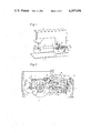
- FIG. 3 is a section taken along the line III--III of FIG. 1;
- FIG. 4 is a section taken along the line IV--IV of FIG. 2;
- FIG. 5 is a section taken along the line V--V of FIG. 4.
- FIG. 6 is a top plan view of one of the operating elements shown in FIG. 1.
- a zigzag sewing machine for sewing fabric which comprises a sewing machine housing which includes an upper arm portion 1 mounted on the top of a column portion 2 which in turn is mounted on a base portion 3, which includes a bottom plate part 4 which underlies a fabric carrying arm 5 of the base portion 3.
- the base portion 3 is provided with a widened front part forming a console having a console top surface 3a with a plurality of openings therein for operating elements or keys 38 which project outwardly therefrom.
- the console surface 3a has an opening for a selector disc 25.
- the fabric carrying arm is offset rearwardly with respect to the remaining portion of base 3 and the stitch-forming tools, in particular, the rotary hook of the sewing machine, is mounted in this portion.
- a lower shaft 10 which serves to drive the hook (not shown), in a known manner, through a gear 7 (FIG. 2) drives a toothed belt 8, a gear 9 (FIG. 3) and a main shaft 6, mounted in the machine's upper arm.
- a bracket 11 is fastened in the machine's base 3 (FIGS. 3 and 4) by means of screws 12.
- a shaft 13 is mounted in two bearings in the bracket 11.
- Shaft 13 has a loosely mounted block 14, consisting of a series of control cams 15 disposed one behind the other, preceded by a gear 16.
- Gear 16 meshes with a gear 17 mounted on the shaft 10.
- the transmission ratio between gear 17 and gear 16 is 6:1.
- a positioning crank 18, rigidly connected to a gear segment 19, is rotatably mounted to the end of shaft 13.
- Positioning crank 18 is guided axially by a retaining ring 20 fastened in an annular slot in the shaft 13.
- Gear segment 19 meshes with a second gear segment 21 which is fastened to an angular lever 22, mounted on a pivot pin 23, fastened in the bracket 11 and it carries a stop 24.
- the stop 24 projects between two positioning cams 26 and 27 formed on the one face of a setting disc 25.
- the setting disc 25 is mounted so as to be rotatable about a shoulder screw 28 fastened to the bracket 11.
- the arm of the angular lever 22 carrying the stop 24 has a point of engagement 29 to which one end of a spring 30 is hooked whose other end is hooked to a point of engagement 31 at an arm of the gear segment 19.
- the two points of engagement 29 and 31 are disposed on parts of the drive connection which move in the same direction.
- the transmission ratio of the system formed by the angular lever 22 and the gear segments 21 and 19 of the drive connection is selected so that the point of engagement 31 disposed near the positioning member 18 travels a longer distance during their common motions than the point of engagement 29. Since the spring 30 assumes its least extended position, it turns the system, so that the stop 24 contacts the inner positioning cam 26.
- a selector is installed in the bracket 11 (FIG. 3).
- a number of levers 34 matching the number of control cams 15 is suspended from a shaft 33 mounted in the bracket 11.
- Each of the levers 34 has a detent arm 35 and an arm 36 which projects upwardly.
- An operating element 38 projecting through an appropriate opening 37 in the top of the base 3 and designed as a key, is attached to each of the arms 36.
- a cam follower 39 having two scanners 40 and 41 is rotatably mounted to each lever 34.
- the levers 34 can each be detained in two positions by a detaining rocker 42 pivoted in the bracket 11.
- their detent arms 35 have a detent 43, each of which can lock in one each of two matching depressions in the detaining rocker 42 which is pushed against the detents 43 by a spring 45.
- the levers 34 have shoulders 46 against which flat springs fastened to the bracket 11 support themselves.
- the flat springs 47 have stops 48 contacted by the raised levers 34.
- the scanners 40 disposed on the one side of the cam followers 39 can interact with one each of the juxtaposed control cams 15 while the scanners 41 disposed on the other side of the cam follower 39 contact a swinging frame 49 mounted in the bracket 11 by means of a shaft 50.
- the swinging frame 49 is connected to a pin 51 which is engaged by a pull rod 52 connected to a needle bar pendulum 55 through a shift lever 53 (FIG. 2), hinged in the upper arm 1, and via a connecting rod 54.
- the needle bar pendulum 55 is hinged to a pin 56 in the upper arm 1 and carries a vertically movable needle bar 57.
- the bar 57 is rigidly joined to a trunnion 58 engaged by a guide rod 59 which is hinged to a crank 60 fastened to the main shaft 6.
- An angular lever 61 is mounted on the shaft 33 (FIG. 4).
- the lever 61 has a guide pin 62 which projects into a control slot 63 in the face of the setting disc 25 opposite the face with the setting cams 26 and 27.
- a feeler arm 64 which has a feeler 66 pushing against a control cam 65 and a feeler 68 directed towards a stop 67 rigidly joined to the gear segment 21 is mounted to the angular lever 61.
- the control cam 65 is rigidly joined to the gear 16.
- the positioning member 18 of FIG. 5 is connected through a pin 69 to a guide rod 70 hinged by means of a pin 71 to another guide rod 72.
- Pin 71 is engaged by an eccentric rod 73 encompassing an eccentric 74 mounted on the shaft 10.
- the guide rod 72 of FIG. 2 is connected to one arm of an angular lever 75 fastened to a shaft 76 mounted in the fabric carrying arm 5.
- Another arm of the angular lever 75 projects upwardly, has a guide slot at its end, in which a pin 77 is guided.
- the pin 77 is fastened to a carrying arm 78 which is movably mounted on a horizontal shaft 79 fastened in the fabric carrying arm 5 parallel to the feed direction.
- the carrying arm 78 supports a fabric transport 80 at its free end, whose teeth act upon the fabric being sewn through slots in a stitch plate 81.
- the carrying arm 78 supports itself on a lifting cam 82 fastened to the shaft 10.
- a lever arm 83 which projects upwardly into the path of an arm 84 of an operating lever 85 and interacts therewith to reverse the feed direction to backstitching, is fastened to the gear segment 21 (FIG. 4).
- the operating lever 85 is mounted in the column 2 of the machine and is braced against an upper stop 87 by a spring 86 anchored to it and to the column 2.
- the positioning cams 26 and 27 provided on the setting disc 25 are designed inverse to each other, i.e., the feeds settable by it in forward and reverse directions are each the same in size.
- the inner positioning cam 26 serves to set the feed in a feeding direction, with the stop 24 normally resting against it.
- the positioning cam 27 serves the purpose of switching the feed direction to reverse by moving the stop 24 against the cam.
- the positioning cams 26 and 27 are designed so that the feed can be changed from a minimum to a maximum by the positioning cam 26, while the positioning cam 26 is outside of the normal range of motion of stop 24.
- the operating elements 38 (FIG. 6) each carry two symbols 88 and 89 of sewing patterns which can be selected after the actuation of the respective operating element 38.
- the symbols can be of different color.
- the sewing machine operates in the following manner:
- the eccentric 74 (FIGS. 2 and 5) which pivots the angular lever 75 via the eccentric rod 73 and the guide rod 72 co-rotates with the shaft 10, with guide rod 72 thereby imparting translatory motions to the carrying arm 78 and, thus, also to the fabric transport 80.
- the lifting motion of the fabric transport 80 by the lifting cam 82 fastened to shaft 10 takes place in harmony with the translatory motion, in which the teeth of the fabric transport 80 rise above the surface of the stitch plate 81, engaging the material being sewn.
- the setting of the size of the feeding steps by the fabric transport 80 is accomplished by moving setting disc 25 (FIG. 4), if the stop is within the adjustment range a of the positioning cams 26 and 27.
- the stop 24 rests against the inner positioning cam 26 under the influence of the spring 30 and moves the positioning member 18 through the angular lever 22 and the two gear segments 21 and 19, with the pin 69 serving as a pivot pin for the guide rod 70 (FIGS. 3 and 5).
- the guide rod 70 performs a relative motion around its hinge point on the angular lever 75, in addition to this rotary motion.
- This relative motion is transmitted as a translatory motion to the carrying arm 78 via the angular lever 75.
- the carrying arm 78 slides back and forth on the shaft 79, thereby imparting translatory motions to the fabric transport 80 fastened to its free end, the size of which depends on the setting of the set screw 25.
- Reversing the fabric transport 80 to back-stitching is accomplished by depressing the operating lever 85 (FIG. 4) against the pull of spring 86.
- the arm then pivots the lever arm 83 counterclockwise in FIG. 4 so that the gear segment 21 connected to the arm 84 pivots the angular lever 22 until the stop 24 contacts the positioning cam 27.
- the positioning member 18 is pivoted by the gear segment 19 into its position intended for sewing backwards.
- the deflection amplitude of the needle bar pendulum 55 is controlled by actuating one of the operating elements 38 (FIG. 3).
- the associated lever 34 When depressing an operating element 38, the associated lever 34 is pivoted down and its detent 43 locks in the lower depression 44 of the detaining rocker 42.
- a lever 34 previously detained in the depression 44 is pushed upwardly by the associated flat spring 47 against the stop 48 of elastic design for noise suppression.
- the detent 43 of lever 34 freely enters the upper depression 44.
- the cam follower 39 which is hinged to it is caused to contact the associated control cam 15 and the swinging frame 49. Therefore, as the block 14 revolves, the selected control cam 15 pivots the swinging frame 49 via the associated cam follower 39, with the swinging frame 49 thereby deflecting the needle bar pendulum 55 in accordance with the contour of the selected control cam 15 via the pin 51 connected to the swinging frame 49, the pull rod 52 and the connecting rod 54. This causes the sewing machine to sew a sewing pattern corresponding to the lower symbol 88 on the operating element 38 of the depressed lever 34.
- the positioning cam 25 pivots the angular lever 61 through the guide pin 62 engaging its control slot 63 so that the scanner 68 of the cam follower 64 rests against the stop 67 of the gear segment 21 and its scanner 66 against the control cam 65, on the gear 61.
- the control cam 65 in addition to the selected control cam 15, which causes the lateral deflection of the needle bar pendulum 55, now controls the motion of the positioning member 18 via the cam follower 64, the stop 67 and the gear segments 21 and 19.
- the design of the control cam 65 is such that the fabric transport 80 performs two feed steps in a forward direction and one subsequent feed step in a reverse direction. Due to this combined control of the needle bar pendulum 55 and fabric transport 80, the sewing machine sews a sewing pattern corresponding to the upper symbol 89 on the operating element 38 of the depressed lever 34.
- the two basic colors of the symbols 88 have also been used to letter the setting disc 25 for the selection of the two setting ranges a and b so that the setting disc 25 can be set unmistakably to the desired one of the two symbols 88 or 89 of the selected operating element 38.
- control cams 15 may also be connected, in a manner known per se, to the positioning crank 18 for the control of the feed motion of the fabric transport 80 instead of to the needle bar 57, by means of transmission elements provided between the control cams 15 and the positioning crank 18, which is designed analogous to the described arrangement between the control cams 15 and the swinging frame 49.
- the contour of these control cams 15 must then be adapted to the feed and feed direction of the fabric transport 80 to be controlled.
- the cams are connectable by a selector 32 to transmission elements for the adjustment of the overstitch width of the needle bar 57 and/or of the fabric transport 80.
- the control cams 15 and 65 and the selector 32 are mounted to one common bracket 11 which is fastened in the base of the machine.
- the positioning member 18 for the control of the feed and feed direction of the fabric transport 80 is mounted coaxial to the control cams 15 and 65.
Landscapes
- Engineering & Computer Science (AREA)
- Textile Engineering (AREA)
- Sewing Machines And Sewing (AREA)
Applications Claiming Priority (4)
| Application Number | Priority Date | Filing Date | Title |
|---|---|---|---|
| DE2839963 | 1978-09-14 | ||
| DE19782839963 DE2839963C2 (de) | 1978-09-14 | 1978-09-14 | Zierstichnähmaschine |
| DE2840209 | 1978-09-15 | ||
| DE19782840209 DE2840209C2 (de) | 1978-09-15 | 1978-09-15 | Zickzacknähmaschine mit einer Mehrzahl koaxial auf einer Achse angeordneter Steuerkurven |
Publications (1)
| Publication Number | Publication Date |
|---|---|
| US4297956A true US4297956A (en) | 1981-11-03 |
Family
ID=25775718
Family Applications (1)
| Application Number | Title | Priority Date | Filing Date |
|---|---|---|---|
| US06/073,635 Expired - Lifetime US4297956A (en) | 1978-09-14 | 1979-09-10 | Zigzag sewing machine having base-mounted operating elements for controlling sewing |
Country Status (2)
| Country | Link |
|---|---|
| US (1) | US4297956A (de) |
| EP (1) | EP0009107B1 (de) |
Cited By (5)
| Publication number | Priority date | Publication date | Assignee | Title |
|---|---|---|---|---|
| US4441440A (en) * | 1982-12-14 | 1984-04-10 | The Singer Company | Push-button control module for a sewing machine |
| US4442784A (en) * | 1982-12-14 | 1984-04-17 | The Singer Company | Vertically stacked components in a control module for a sewing machine |
| US4487141A (en) * | 1984-05-29 | 1984-12-11 | The Singer Company | Force amplifying arrangement for sewing machine pushbutton control |
| US4499837A (en) * | 1982-05-20 | 1985-02-19 | Aisin Seiki Kabushiki Kaisha | Stitch pattern selector in sewing machines |
| US4612821A (en) * | 1983-01-28 | 1986-09-23 | The Singer Company | Spring system for push-button control in a sewing machine |
Families Citing this family (1)
| Publication number | Priority date | Publication date | Assignee | Title |
|---|---|---|---|---|
| CH668445A5 (de) * | 1985-02-07 | 1988-12-30 | Gegauf Fritz Ag | Spulvorrichtung fuer naehmaschine. |
Citations (5)
| Publication number | Priority date | Publication date | Assignee | Title |
|---|---|---|---|---|
| US3257980A (en) * | 1955-10-29 | 1966-06-28 | Brother Ind Ltd | Cam selecting mechanism for sewing machines |
| US3279402A (en) * | 1958-04-08 | 1966-10-18 | Janome Sewing Machine Co Ltd | Cam selecting arrangement for zig-zag stitch sewing machine |
| US3356051A (en) * | 1963-10-28 | 1967-12-05 | Janome Sewing Machine Co Ltd | Cam selecting arrangment |
| US4066029A (en) * | 1976-01-12 | 1978-01-03 | The Singer Company | Electromechanical remote cam selector for sewing machines |
| DE2735428A1 (de) * | 1976-08-06 | 1978-02-09 | Janome Sewing Machine Co Ltd | Naehmaschine |
Family Cites Families (11)
| Publication number | Priority date | Publication date | Assignee | Title |
|---|---|---|---|---|
| BE387244A (de) * | 1928-08-16 | |||
| BE542467A (de) * | 1953-11-19 | |||
| US2971482A (en) * | 1955-06-02 | 1961-02-14 | Nippon Sewing Machine Mfg Co L | Automatic zigzag-stitch sewing machine |
| US2822771A (en) * | 1955-09-30 | 1958-02-11 | Singer Mfg Co | Sewing machines |
| FR1260526A (fr) * | 1959-06-24 | 1961-05-05 | Flii Borletti | Dispositif de déplacement du tissu dans les machines à coudre |
| US3105449A (en) * | 1961-03-16 | 1963-10-01 | Singer Co | Zigzag actuating mechanism for sewing machines |
| CH400737A (de) * | 1962-04-26 | 1965-10-15 | Pfaff Ag G M | Einrichtung an Nähmaschinen zum Nähen von Ziernähten |
| US3357384A (en) * | 1965-12-10 | 1967-12-12 | Merrow Machine Co | Feeding mechanism for sewing machine |
| BE694377A (de) * | 1966-03-01 | 1967-07-31 | ||
| US3874312A (en) * | 1974-01-23 | 1975-04-01 | Singer Co | Electric cam selector mechanism for sewing machines |
| JPS5922547B2 (ja) * | 1975-03-28 | 1984-05-28 | ブラザー工業株式会社 | ミシンのプログラム装置 |
-
1979
- 1979-08-06 EP EP79102828A patent/EP0009107B1/de not_active Expired
- 1979-09-10 US US06/073,635 patent/US4297956A/en not_active Expired - Lifetime
Patent Citations (5)
| Publication number | Priority date | Publication date | Assignee | Title |
|---|---|---|---|---|
| US3257980A (en) * | 1955-10-29 | 1966-06-28 | Brother Ind Ltd | Cam selecting mechanism for sewing machines |
| US3279402A (en) * | 1958-04-08 | 1966-10-18 | Janome Sewing Machine Co Ltd | Cam selecting arrangement for zig-zag stitch sewing machine |
| US3356051A (en) * | 1963-10-28 | 1967-12-05 | Janome Sewing Machine Co Ltd | Cam selecting arrangment |
| US4066029A (en) * | 1976-01-12 | 1978-01-03 | The Singer Company | Electromechanical remote cam selector for sewing machines |
| DE2735428A1 (de) * | 1976-08-06 | 1978-02-09 | Janome Sewing Machine Co Ltd | Naehmaschine |
Cited By (5)
| Publication number | Priority date | Publication date | Assignee | Title |
|---|---|---|---|---|
| US4499837A (en) * | 1982-05-20 | 1985-02-19 | Aisin Seiki Kabushiki Kaisha | Stitch pattern selector in sewing machines |
| US4441440A (en) * | 1982-12-14 | 1984-04-10 | The Singer Company | Push-button control module for a sewing machine |
| US4442784A (en) * | 1982-12-14 | 1984-04-17 | The Singer Company | Vertically stacked components in a control module for a sewing machine |
| US4612821A (en) * | 1983-01-28 | 1986-09-23 | The Singer Company | Spring system for push-button control in a sewing machine |
| US4487141A (en) * | 1984-05-29 | 1984-12-11 | The Singer Company | Force amplifying arrangement for sewing machine pushbutton control |
Also Published As
| Publication number | Publication date |
|---|---|
| EP0009107A2 (de) | 1980-04-02 |
| EP0009107B1 (de) | 1984-06-13 |
| EP0009107A3 (en) | 1980-06-25 |
Similar Documents
| Publication | Publication Date | Title |
|---|---|---|
| KR100343605B1 (ko) | 미싱의중압체높이조정장치 | |
| GB2121445A (en) | Waiting arrangement in an embroidering machine | |
| US4297956A (en) | Zigzag sewing machine having base-mounted operating elements for controlling sewing | |
| US4756263A (en) | Fabric feed device of a sewing machine | |
| US3254618A (en) | Buttonhole stitching control device | |
| US4546717A (en) | Sewing machine differential feed | |
| US3040682A (en) | Sewing machines | |
| US4759304A (en) | Device for control and regulation of upper feed mechanism of overlock sewing machine | |
| US3156205A (en) | Sewing machine mechanism for decorative stitching | |
| US4244311A (en) | Zigzag sewing machine with a pattern selecting device | |
| US4106419A (en) | Sewing machine | |
| US3096737A (en) | Fabric feeder mechanism for sewing machine | |
| US5063867A (en) | Zigzag sewing machine | |
| US5101748A (en) | Feed dog drive for sewing machines | |
| US4056071A (en) | Combination presser bar lifters and pressure controls | |
| US5313900A (en) | Feed direction and stitch length cam for zigzag sewing machine | |
| US4392441A (en) | Sewing machine with buttonhole stitching mechanism | |
| US4380204A (en) | Needle and feed cam arrangement for a zig zag sewing machine | |
| US2849972A (en) | Button hole attachment for sewing machine | |
| US4244310A (en) | Zigzag sewing machine with a trimming device | |
| JPS6036311B2 (ja) | ジグザグミシン | |
| US5249541A (en) | Feed regulator of a sewing machine | |
| JP3818686B2 (ja) | ミシンの糸調子迅速切替え装置 | |
| US3020865A (en) | Sewing machine for producing variable stitches | |
| US4594958A (en) | Presser foot lift device for a top feed sewing machine |
Legal Events
| Date | Code | Title | Description |
|---|---|---|---|
| STCF | Information on status: patent grant |
Free format text: PATENTED CASE |
|
| AS | Assignment |
Owner name: G.M. PFAFF AKTIENGESELLSCHAFT, GERMANY Free format text: ASSIGNMENT OF ASSIGNORS INTEREST;ASSIGNOR:DORINA NAHMASCHINEN GMBH;REEL/FRAME:007476/0236 Effective date: 19950314 |