US4167380A - Apparatus for the manufacture of layered articles such as multilayer tablets - Google Patents
Apparatus for the manufacture of layered articles such as multilayer tablets Download PDFInfo
- Publication number
- US4167380A US4167380A US05/828,964 US82896477A US4167380A US 4167380 A US4167380 A US 4167380A US 82896477 A US82896477 A US 82896477A US 4167380 A US4167380 A US 4167380A
- Authority
- US
- United States
- Prior art keywords
- feeding device
- feeding
- dies
- path
- compressing
- Prior art date
- Legal status (The legal status is an assumption and is not a legal conclusion. Google has not performed a legal analysis and makes no representation as to the accuracy of the status listed.)
- Expired - Lifetime
Links
- 238000004519 manufacturing process Methods 0.000 title abstract description 13
- 239000000463 material Substances 0.000 claims abstract description 21
- 230000008878 coupling Effects 0.000 claims 1
- 238000010168 coupling process Methods 0.000 claims 1
- 238000005859 coupling reaction Methods 0.000 claims 1
- 230000006835 compression Effects 0.000 abstract description 4
- 238000007906 compression Methods 0.000 abstract description 4
- 238000005259 measurement Methods 0.000 abstract description 3
- 238000000034 method Methods 0.000 description 9
- 238000006073 displacement reaction Methods 0.000 description 6
- 230000008901 benefit Effects 0.000 description 4
- 238000010276 construction Methods 0.000 description 4
- 239000011236 particulate material Substances 0.000 description 4
- 239000000126 substance Substances 0.000 description 2
- 230000009471 action Effects 0.000 description 1
- 230000001464 adherent effect Effects 0.000 description 1
- 230000005540 biological transmission Effects 0.000 description 1
- 238000004140 cleaning Methods 0.000 description 1
- 230000000694 effects Effects 0.000 description 1
- 230000009969 flowable effect Effects 0.000 description 1
- 238000012986 modification Methods 0.000 description 1
- 230000004048 modification Effects 0.000 description 1
- 238000011022 operating instruction Methods 0.000 description 1
- 239000000843 powder Substances 0.000 description 1
- 230000001681 protective effect Effects 0.000 description 1
- 230000008439 repair process Effects 0.000 description 1
Images


Classifications
-
- B—PERFORMING OPERATIONS; TRANSPORTING
- B30—PRESSES
- B30B—PRESSES IN GENERAL
- B30B15/00—Details of, or accessories for, presses; Auxiliary measures in connection with pressing
- B30B15/30—Feeding material to presses
- B30B15/302—Feeding material in particulate or plastic state to moulding presses
- B30B15/304—Feeding material in particulate or plastic state to moulding presses by using feed frames or shoes with relative movement with regard to the mould or moulds
- B30B15/306—Feeding material in particulate or plastic state to moulding presses by using feed frames or shoes with relative movement with regard to the mould or moulds for multi-layer articles
-
- Y—GENERAL TAGGING OF NEW TECHNOLOGICAL DEVELOPMENTS; GENERAL TAGGING OF CROSS-SECTIONAL TECHNOLOGIES SPANNING OVER SEVERAL SECTIONS OF THE IPC; TECHNICAL SUBJECTS COVERED BY FORMER USPC CROSS-REFERENCE ART COLLECTIONS [XRACs] AND DIGESTS
- Y10—TECHNICAL SUBJECTS COVERED BY FORMER USPC
- Y10S—TECHNICAL SUBJECTS COVERED BY FORMER USPC CROSS-REFERENCE ART COLLECTIONS [XRACs] AND DIGESTS
- Y10S425/00—Plastic article or earthenware shaping or treating: apparatus
- Y10S425/804—Capsule making
Definitions
- the invention relates generally to an apparatus and method for the manufacture of multilayer articles.
- the invention is particularly concerned with the manufacture of multilayer tablets such as are used, for example, for medicinal purposes.
- a known apparatus for the manufacture of multilayertablets has a rotary disc on which there are mounted several female dies.
- a minimum of two feeding devices for supplying the female dies with flowable material are arranged adjacent the rotary disc.
- Compressing devices are provided and cooperate with the female dies to compress the material fed into these dies. The compressing devices also cause adjacent layers to adhere to one another.
- control purposes require that it be possible to determine the weight of the first compressed layer. This is necessary since the weight of the second layer, which is pressed onto the first layer and is often constituted by the working substance of the tablets, is determined on the basis of the weight of the first layer.
- an apparatus for making multilayer articles, particularly tablets includes at least one female die movable along a predetermined path, e.g., a circular path, and at least one feeding device for admitting material into the female die.
- the feeding device is movable between operative and inoperative positions in which feeding of material into the female die is respectively permitted and prevented.
- the feeding device is arranged so that movement between these positions can occur while the female die travels along its predetermined path.
- Means is provided for moving the feeding device between its operative and inoperative positions.
- Such an apparatus may comprise a rotary disc carrying female dies as well as first and second feeding stations for respectively admitting the first and second layers of the tablets into the female dies as these rotate by the feeding stations.
- a first compressing station may be associated with the first feeding station whereas a second compressing station may be associated with the second feeding station.
- the first compressing station will usually be located downstream of the first feeding station as seen along the direction of rotation of the female dies and, similarly, the second compressing station will usually be located downstream of the second feeding station as seen along the direction of rotation of the female dies.
- first and second feeding stations or to first and second feeding devices and compressing stations
- this is not intended to limit the invention to an apparatus with two feeding devices and/or two compressing stations.
- This terminology i.e., "first” and “second,” has been chosen inasmuch as the manufacture of tablets having two layers is being described.
- the invention is, however, equally applicable to apparatus for the manufacture of tablets having three, four or more layers since the same problems which the invention intends to overcome exist and may be solved using the inventive means.
- Such apparatus for making tablets with more than two layers could correspondingly have three, four or more feeding devices and three, four or more compressing stations.
- the feeding devices are, in accordance with the invention, provided with their own drive means via which they may be moved between operative and inoperative positions individually or, at least to some extent, simultaneously during rotation of the rotary disc carrying the female die.
- the operative position of a feeding device is one in which the feeding device projects into or overlaps the path of the female dies.
- the inoperative position of a feeding device is one in which the latter does not project into or overlap the path of the female dies.
- a displaceable feeding device is moved away from the rotary disc. This permits the compressing station located downstream of the retracted feeding device to be used for effecting a further compression of the test sample, without the addition of new material from the retracted feeding device, before the test sample is ejected from the female die.
- the test sample is given additional strength by being subjected to a further compression while, at the same time, there is need to readjust any compressing station when the retracted feeding device has been returned to its operative position.
- a feeding device for a rotary disc carrying female dies that the feeding device may be moved away from the rotary disc as a complete structural entity after loosening screw connections or bolts.
- This is intended to permit the repair of component parts as well as the performance of other functions such as, for example, cleaning of the feeding device.
- this arrangement is not suited for the performance of control tests on the tablets or for determining the weights of one or more layers of the latter.
- the applicable operating instructions specify that demounting of the feeding device, as well as other manipulations on the apparatus, be performed only when the rotary disc is at a standstill.
- a displaceable feeding device is movable along a substantially straight line. It is further of advantage for the feeding device to be provided with guide rollers in order to achieve this and for the guide rollers to be mounted for movement in a guide slot of a support plate or the like. Such an arrangement enables the linear displacement between the operative and inoperative positions to be accomplished quickly and easily.
- the feeding device is favorably provided with a piston rod which can be pneumatically, hydraulically or electrically driven.
- the feeding device By moving the feeding device to its inoperative position for a short period of time, a construction of this type makes it possible to obtain test samples without interruption in the operation of the apparatus, as well as adjust the apparatus while it is running and to thereafter produce more multilayer tablets.
- the test samples may be obtained while the apparatus is running at full speed beneath the conventional protective hood.
- This is also possible with relatively large, that is, heavy, apparatus and can be accomplished without the need for moving the drive means or motor which is provided for displacing the feeding device and which may, for instance, be mounted above the feeding device, together with the latter.
- the feeding device is connected with its drive motor via a telescope-like or extensible articulated linkage.
- a flexible hose or tube may be utilized.
- a method according to the invention of manufacturing multilayer articles, particularly multilayer tablets involves moving a female die along a predetermined path, e.g., a circular path, and admitting a layer of material into the female die from a feeding device stationed along the path in an operative feeding position.
- the layer is densified, e.g., compressed, at a densifying station along the path and an additional layer of material is admitted into the female die from a feeding device stationed along the path in an operative feeding position.
- Both of the layers are now densified, e.g., compressed, at a densifying station along the path and the layers are caused to adhere to one another.
- the adherent layers are ejected from the female die.
- a sample for control purposes is obtained by: admitting one of the layers into the female die from a feeding device stationed along the path in an operative feeding position; densifying, e.g. compressing, this layer at a densifying station along the path; displacing the feeding device which admits the other layer into the female die to an inoperative feeding position while the female die moves along its path so as to prevent admission of this other layer into the female die; densifying, e.g. compressing, the layer which is in the female die again at a densifying station along the path so that the cohesiveness of the layer is increased sufficiently to permit ejection thereof from the female die substantially as a cohesive unit; and ejecting the thus-densified layer from the female die.
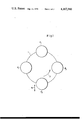
- FIG. 1 diagrammatically illustrates an apparatus according to the invention having a rotary disc with two associated feeding devices and two associated compressing devices;
- FIG. 2 is a partly sectional top view of a feeding device and a drive for the displacement thereof in accordance with the invention
- FIG. 3 is a partly sectional side view of the drive of FIG. 2;
- FIG. 4 is a partly sectional front view of the drive of FIG. 2.
- FIGS. 1-4 The apparatus illustrated in FIGS. 1-4 is here assumed to be an apparatus for manufacturing multilayer tablets for medicinal or other purposes.
- the apparatus includes a rotary disc 1 which rotates in a counterclockwise direction indicated by the arrow 2.
- the disc 1 is adapted to carry female dies.
- the illustrated apparatus is intended for the manufacture of two-layer tablets.
- two feeding stations F1 and F2 are provided at diametrically opposite locations of the disc 1.
- a pair of compressing stations P1 and P2 is arranged between the feeding stations F1 and F2 so that the compressing station P1 is located immediately downstream of the feeding station F1 in the direction of rotation of the disc 1 and the compressing station P2 is located immediately downstream of the feeding station F2 in the direction of rotation of the disc 1.
- the compressing station P1 and P2 may, for example, include male dies adapted to cooperate with the female dies carried by the rotary disc 1.
- a first layer of particulate material e.g. powder
- This first layer of particulate material is precompressed at the compressing station P1.
- a second layer is admitted into the female dies mounted on the rotary disc 1. The second layer is compressed together with the first layer at the compressing station P2 and the two compressed layers adhere to one another upon leaving the compressing station P2 so that a two-layer tablet is obtained.
- the finished tablet is ejected from its female die between the compressing station P2 and the first feeding station F1.
- the feeding stations F1 and F2 may be moved out of the path of rotation of the female dies while the rotary disc 1 rotates.
- both of the feeding stations F1 and F2 are provided with individual drive means.
- FIG. 2 further illustrates that a conventional drive 26 is provided for rotating the rotary disc 1.
- the feeding station F2 is seen to have a bottom plate 4 on which there is mounted a transmission gear housing 5.
- a feeding wheel 6 provided with radially extending vanes 7 is driven by gear 6' in the housing 5 and rotates in clockwise direction in the bottom plate 4 as indicated by the arrow 8.
- the vanes 7 overlap the female dies 3 and thus fill particulate tablet material into the female dies 3.
- a dosing wheel 9 is arranged behind the feeding wheel 6 in the direction of rotation of the rotary disc 1.
- the dosing wheel 9 has bent vanes 10 and is driven by gear 9' to rotate in counterclockwise direction as indicated by the arrow 11.
- the vanes 10 of the dosing wheel 9 remove excess particulate material which piles up on the female dies 3 and convey the excess material back to the working region of the feeding wheel 6.
- Fresh particulate material is brought to the feeding wheel 6 via a non-illustrated hose connected to the inlet port 5' on the upper side of the housing 5.
- the feeding station F2 is mounted for linear displacement in two opposite directions as indicated by arrow 15, on a stationary support or carrier plate 12. For its displacement, the feeding station F2 is provided with guide and drive elements 13 to 23 as will be explained below.
- a compressed air cylinder 13 is provided for moving the feeding station F2.
- a piston is mounted in the cylinder 13 for back-and-forth movement therein and is connected with a piston rod 14.
- the piston rod 14 moves back-and-forth in the manner indicated by the double-headed arrow 15.
- a plate 16 is secured to that end of the piston rod 14 remote from the cylinder 13 and carries a bridge member 17.
- a pair of guide rollers 18 and 19 is rotatably mounted on the bridge member 17.
- the guide rollers 18 and 19 run in a guide slot 20 provided in the stationary carrier plate 12.
- the guide rollers 18 and 19 have shafts 22 and 23, respectively.
- the shafts 22 and 23 are screwed into the bottom plate 4 of the feeding station F2 at the lower side of the bottom plate 4.
- the feeding station F2 comprising the bottom plate 4 and the drive housing 5 is similarly moved back-and-forth due to the fact that it shifts on the stationary carrier plate 12.
- the range over which the feeding station F2 can be displaced in guide slot 20 is such that in one terminal position thereof in which roller 18 abuts against the outer end of slot 20, the female dies 3 can move by the feeding station F2 out of the range of vanes 7, that is, without being filled, whereas in the other terminal position thereof (in operative position as shown in FIG. 2) the female dies 3 are overlapped by vanes 7 in the feeding station F2, that is, are filled by the latter.
- An exemplary, but non-limiting, range of movement for the feeding station F2 is 4 centimeters.
- Locking of the feeding station F2 in its operative position may, for example, be accomplished as shown in FIG. 3.
- a locking action is achieved by means of a wedge 24 which is secured to the carrier plate 12 and causes the feeding station F2 to be pulled downwardly via the bottom plate 4 thereof.
- a separate drive motor "A” is provided for driving the gears 6' and 9' in housing 5 of the feeding station F2.
- the gearing in the housing 5 of the feeding station F2 is driven by the drive motor "A” via a telescope-like or extensible articulated linkage 25. Only the lower portion of the articulated linkage 25 is shown, and the pivots corresponding to this portion of the articulated linkage 25 may be clearly seen.
- the upper portion of the articulated linkage 25, which is located beneath the drive motor "A,” is constructed similarly to the lower portion of the articulated linkage 25.
- the articulated linkage 25 is designed so that angular movement, as well as axial extension, may occur.
Landscapes
- Engineering & Computer Science (AREA)
- Mechanical Engineering (AREA)
- Medical Preparation Storing Or Oral Administration Devices (AREA)
- Basic Packing Technique (AREA)
Applications Claiming Priority (2)
| Application Number | Priority Date | Filing Date | Title |
|---|---|---|---|
| DE2639090A DE2639090C3 (de) | 1976-08-31 | 1976-08-31 | Tablettiermaschine |
| DE2639090 | 1976-08-31 |
Publications (1)
| Publication Number | Publication Date |
|---|---|
| US4167380A true US4167380A (en) | 1979-09-11 |
Family
ID=5986748
Family Applications (1)
| Application Number | Title | Priority Date | Filing Date |
|---|---|---|---|
| US05/828,964 Expired - Lifetime US4167380A (en) | 1976-08-31 | 1977-08-29 | Apparatus for the manufacture of layered articles such as multilayer tablets |
Country Status (6)
| Country | Link |
|---|---|
| US (1) | US4167380A (enExample) |
| BE (1) | BE858093A (enExample) |
| DE (1) | DE2639090C3 (enExample) |
| FR (1) | FR2363432A1 (enExample) |
| GB (1) | GB1581890A (enExample) |
| IT (1) | IT1079926B (enExample) |
Cited By (4)
| Publication number | Priority date | Publication date | Assignee | Title |
|---|---|---|---|---|
| US4219320A (en) * | 1979-07-11 | 1980-08-26 | Wilhelm Fette Gmbh | Preforming press |
| US4362491A (en) * | 1981-02-05 | 1982-12-07 | Ed Frogerais Sa | Tablet making machines |
| US4714420A (en) * | 1982-12-20 | 1987-12-22 | Ptp Patentierte Technologische Prozesse Ag | Plant for the continuous and automated manufacturing of agglomerated sintered, vulcanized and pressed articles |
| US9839212B2 (en) * | 2015-04-16 | 2017-12-12 | Bio-Lab, Inc. | Multicomponent and multilayer compacted tablets |
Families Citing this family (4)
| Publication number | Priority date | Publication date | Assignee | Title |
|---|---|---|---|---|
| DE4025487A1 (de) * | 1990-08-08 | 1992-02-13 | Korsch Maschfab | Fuellgeraet fuer die matrizen einer tablettiermaschine |
| DE4218122C1 (de) * | 1992-06-02 | 1994-01-20 | Fette Wilhelm Gmbh | Verfahren zum Pressen von Zweischichttabletten in einer Doppelrundläuferpresse und Vorrichtung zur Durchführung des Verfahrens |
| DE19502841A1 (de) * | 1995-01-30 | 1996-08-01 | Dorst Masch & Anlagen | Pulverpresse mit mechanisch-hydraulischer Füllschuhsteuerung |
| DE102011101286B4 (de) | 2011-05-10 | 2013-10-17 | Fette Compacting Gmbh | Rundläuferpresse und Verfahren zum Betreiben einer Rundläuferpresse |
Citations (6)
| Publication number | Priority date | Publication date | Assignee | Title |
|---|---|---|---|---|
| US2218456A (en) * | 1938-02-12 | 1940-10-15 | Owens Illinois Glass Co | Apparatus for molding plastic materials |
| US2717417A (en) * | 1951-04-13 | 1955-09-13 | Canby A Rigsby | Apparatus for molding electrical contact brushes |
| US2970554A (en) * | 1959-01-09 | 1961-02-07 | Bristol Myers Co | Tablet press |
| US3599283A (en) * | 1969-05-05 | 1971-08-17 | G & B Automated Equipment Ltd | Machine for use in the manufacture of grinding wheels |
| US3633245A (en) * | 1969-04-28 | 1972-01-11 | Packaging Research Corp | Apparatus for making and dispensing coherent masses of a bulk material |
| US3744950A (en) * | 1970-06-09 | 1973-07-10 | P Courtois | Pressure molding device |
Family Cites Families (2)
| Publication number | Priority date | Publication date | Assignee | Title |
|---|---|---|---|---|
| FR1278324A (fr) * | 1960-02-15 | 1961-12-08 | Kilian & Co G M B H | Dispositif destiné à la confection de comprimés à au moins deux couches |
| GB952006A (en) * | 1962-02-21 | 1964-03-11 | John Holroyd & Company Ltd | Multi-layer tablet making machines |
-
1976
- 1976-08-31 DE DE2639090A patent/DE2639090C3/de not_active Expired
-
1977
- 1977-08-16 FR FR7725024A patent/FR2363432A1/fr active Granted
- 1977-08-22 IT IT50736/77A patent/IT1079926B/it active
- 1977-08-22 GB GB35150/77A patent/GB1581890A/en not_active Expired
- 1977-08-25 BE BE180415A patent/BE858093A/xx not_active IP Right Cessation
- 1977-08-29 US US05/828,964 patent/US4167380A/en not_active Expired - Lifetime
Patent Citations (6)
| Publication number | Priority date | Publication date | Assignee | Title |
|---|---|---|---|---|
| US2218456A (en) * | 1938-02-12 | 1940-10-15 | Owens Illinois Glass Co | Apparatus for molding plastic materials |
| US2717417A (en) * | 1951-04-13 | 1955-09-13 | Canby A Rigsby | Apparatus for molding electrical contact brushes |
| US2970554A (en) * | 1959-01-09 | 1961-02-07 | Bristol Myers Co | Tablet press |
| US3633245A (en) * | 1969-04-28 | 1972-01-11 | Packaging Research Corp | Apparatus for making and dispensing coherent masses of a bulk material |
| US3599283A (en) * | 1969-05-05 | 1971-08-17 | G & B Automated Equipment Ltd | Machine for use in the manufacture of grinding wheels |
| US3744950A (en) * | 1970-06-09 | 1973-07-10 | P Courtois | Pressure molding device |
Cited By (4)
| Publication number | Priority date | Publication date | Assignee | Title |
|---|---|---|---|---|
| US4219320A (en) * | 1979-07-11 | 1980-08-26 | Wilhelm Fette Gmbh | Preforming press |
| US4362491A (en) * | 1981-02-05 | 1982-12-07 | Ed Frogerais Sa | Tablet making machines |
| US4714420A (en) * | 1982-12-20 | 1987-12-22 | Ptp Patentierte Technologische Prozesse Ag | Plant for the continuous and automated manufacturing of agglomerated sintered, vulcanized and pressed articles |
| US9839212B2 (en) * | 2015-04-16 | 2017-12-12 | Bio-Lab, Inc. | Multicomponent and multilayer compacted tablets |
Also Published As
| Publication number | Publication date |
|---|---|
| FR2363432B1 (enExample) | 1982-12-31 |
| DE2639090A1 (de) | 1978-03-16 |
| IT1079926B (it) | 1985-05-13 |
| FR2363432A1 (fr) | 1978-03-31 |
| BE858093A (fr) | 1977-12-16 |
| DE2639090C3 (de) | 1979-12-06 |
| DE2639090B2 (de) | 1979-04-05 |
| GB1581890A (en) | 1980-12-31 |
Similar Documents
| Publication | Publication Date | Title |
|---|---|---|
| CA1150028A (en) | Apparatus for compressing tablets | |
| US4167380A (en) | Apparatus for the manufacture of layered articles such as multilayer tablets | |
| US4373888A (en) | Apparatus for mass-producing medical tablets | |
| US2946298A (en) | Compression coating tablet press | |
| GB1420906A (en) | Apparatus for charging pressing dies | |
| US5879278A (en) | Method and machine for cutting liners and inserting cut liners into closures | |
| JP3388749B2 (ja) | 回転式錠剤製造装置 | |
| CN205464321U (zh) | 金属粉末药型罩自动化压制生产系统 | |
| US20230002094A1 (en) | Cutting, crimping and stacking machine for conical cornet cone packages | |
| US2287675A (en) | Molding press | |
| GB1089747A (en) | Metering apparatus | |
| US3918873A (en) | Tabletting machines | |
| US3000331A (en) | Coated tablet press | |
| CN214684511U (zh) | 一种智能精准型数显液压摆式剪板机 | |
| US4362493A (en) | Apparatus for compressing tablets | |
| CN106726595A (zh) | 防漏粉可调式充填回转装置 | |
| US2906214A (en) | Pill press apparatus | |
| US582794A (en) | Pill-machine | |
| SE432905B (sv) | Forfarande for pressning av skrymmande gods till baler samt en for genomforande av forfarandet avsedd balpress | |
| CA1184008A (en) | Material feed unit for an injection molding machine | |
| GB2163093A (en) | Spreader mechanism for a powder compacting press | |
| JPH0522398Y2 (enExample) | ||
| JP6512608B2 (ja) | 化粧料用製剤の充填ポンプ装置及び該充填ポンプ装置を使用した化粧料用製剤の充填方法 | |
| US2848741A (en) | Apparatus for feeding powdered or granular materials to receptacles | |
| USRE30319E (en) | Tabletting machines |