US4135709A - Device for preventing the reverse movement of a rotary cylinder used in a paper sheet counter - Google Patents
Device for preventing the reverse movement of a rotary cylinder used in a paper sheet counter Download PDFInfo
- Publication number
- US4135709A US4135709A US05/859,608 US85960877A US4135709A US 4135709 A US4135709 A US 4135709A US 85960877 A US85960877 A US 85960877A US 4135709 A US4135709 A US 4135709A
- Authority
- US
- United States
- Prior art keywords
- stopper
- rotary cylinder
- auxiliary
- grooves
- engageable
- Prior art date
- Legal status (The legal status is an assumption and is not a legal conclusion. Google has not performed a legal analysis and makes no representation as to the accuracy of the status listed.)
- Expired - Lifetime
Links
Images

Classifications
-
- G—PHYSICS
- G06—COMPUTING OR CALCULATING; COUNTING
- G06M—COUNTING MECHANISMS; COUNTING OF OBJECTS NOT OTHERWISE PROVIDED FOR
- G06M9/00—Counting of objects in a stack thereof
- G06M9/02—Counting of objects in a stack thereof by using a rotating separator incorporating pneumatic suction nozzles
Definitions
- This invention relates to a device for preventing the reverse movement of a rotary cylinder used in a paper sheet counter.
- the rotary cylinder is provided on the peripheral wall thereof with grooves and a stopper mounted on a stopper carriage pivotably mounted adjacent the rotary cylinder engages with one of the grooves to stop the rotary cylinder when the counter is not actuated.
- One object of the invention is, therefore, to provide a device for preventing the reverse movement of the rotary cylinder just after the rotary cylinder is freed by disengagement of the stopper from the rotary cylinder thereby preventing a miscount.
- Another object of the invention is to make the above-mentioned device easy to accomplish by merely incorporating an auxiliary stopper means into the conventional stopper means.
- a further object of the invention is to make the above-mentioned device easy to assemble at a low cost.
- FIG. 1 is a schematic plan view showing a portion of a paper sheet counter associated with the present invention.
- FIGS. 2 to 4 are similar schematic views showing a paper sheet counter incorporating a device according to the invention in sequence of operations.
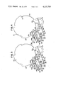
- FIG. 1 there is shown a rotary cylinder 10 provided at one end surface thereof with five equally spaced suction shafts 11.
- the rotary cylinder 10 is rotated in the anticlockwise direction and each of suction shafts 11 interlocked with the rotation of the rotary cylinder is rotated about its own axis in the clockwise direction.
- the rotary cylinder 10 is provided on the peripheral wall thereof with five iron pieces 17 for count, only two of which are shown in the FIG. 1, corresponding to the five suction shafts, respectively.
- a non-contact switch 18 of a counter unit positioned adjacent the rotary shaft, "one" is added to the count.
- a paper sheet holding means 13 for clamping a stack of paper sheets between a holding plate 14 and a retention member 15 is pivotably mounted about its axis, not shown, on the frame of the counter machine, not shown, adjacent the rotary cylinder 10.
- the holding means 13 is interlocked with a stopper carriage, hereinafter described, so that the stopper carriage is rotated together with the rotation of the holding means 13.
- a switch is turned on and a count signal is produced to cause the paper sheet holding means 13 to be rotated up to the position as shown in the FIG. 1, so that each of the suction shafts 11 can sequentially suck and deflect the portion of the outermost sheet from the paper sheet holding means 13 one at a time as the rotary cylinder 10 rotate.
- a stopper carriage 32 is rotated to disengage a stopper 31 carried by the stopper carriage 32 from the groove 21 which is one of five grooves on the rotary cylinder 10, so that the rotary cylinder can move freely.
- the present invention incorporates a device for preventing the reverse movement of the rotary cylinder 10 in the conventional stopping means for the rotary cylinder. The device will now be explained.
- FIGS. 2 to 4 there is shown a portion of the rotary cylinder 10 having on its peripheral wall a set of five equally spaced cut-out grooves 21, 22, 23, 24, 25 provided alternately with a set of five equally spaced cam projections 26, 27, 28, 29, 30.
- This portion of the rotary cylinder shown in the FIGS. 2 to 4 is located below the end surface of the rotary cylinder shown in the FIG. 1 locking in the direction perpendicular to the drawing of the FIG. 1.
- the suction shafts 11, the holding means 13, the non-contact switch 18, etc are not in the FIGS. 2 to 4.
- Each cam projection is constructed so that it curves outwardly in the clockwise direction.
- a U-shaped stopper 31 is positioned opposite to one of the grooves.
- the stopper 31 is attached by a set screw 33 to the stopper carriage 32 which is pivotably mounted on the frame by a pivot pin 34.
- the stopper carriage 32 is provided with a pin 35.
- a spring, not shown, is provided between the pin 35 and the frame to bias the stopper carriage 32 in the anti-clockwise direction about the pivot pin 34.
- the stopper carriage is provided at one end thereof with a metal support 36 by which an auxiliary stop plate 37 is attached to the stopper carriage 32 in parallel thereto.
- a vertical portion 38 integral with or attached to the auxiliary stop plate 37 has a leaf spring 41 attached by screws 40 through spacers 39.
- the leaf spring 41 is formed with an arc portion 41a at the end of the side of the rotary cylinder.
- a lever 43 is pivotably mounted at one end thereof on the end of the auxiliary stop plate 37 by a pivot pin 42. Attached to the other end of the lever 43 is an auxiliary stopper 44 comprising portions 44a, 44b, 44c and 44d.
- the auxiliary stopper 44 may be integral with the lever 43.
- the portion 44d is fitted at free end thereof in the arc portion 41a of the leaf spring and resiliently grasped by the arc portion 41a when the rotary cylinder is stopped or not actuated as shown in the FIG. 2.
- An L-shaped fitting 15 is mounted on the frame on the rear side of the auxiliary stop plate 37 and is positioned opposite to the portion 44c of the auxiliary stopper 44. The L-shaped fitting functions to ristrict the movement of the auxiliary stopper 44 by engaging with the portion 44c when the portion 44d is disengaged from the arc portion 41a of the leaf spring 41 as shown in the FIG. 4.
- a count signal is produced to cause the holding means 13 for clamping a stack of sheets to rotate in the clockwise direction and simultaneously cause the stopper carriage 32 interlocked with the holding means 13 also to rotate in the clockwise direction against the action of the above-mentioned spring provided between the pin 35 and the frame to disengage the stopper 31 from the groove 31 of the rotary cylinder 10.
- the rotary cylinder 10 can, in the conventional counter, move freely since the rotary cylinder is not forwardly driven at the time.
- the auxiliary stopper 44 is caused to jump into the groove 22 of the rotary cylinder 10, described later in detail, to confine the free movement of the rotary cylinder 10 and thereby prevent the reverse movement thereof.
- the auxiliary stop plate 37 attached to the stopper carriage 32 is also rotated in the clockwise direction.
- the auxiliary stopper 44 which is now stationary relative to the auxiliary stop plate 37 due to the engagement of the portion 44d of auxiliary stopper 44 with the arc portion 41a of the leaf spring 41 which is also rotated in the clockwise direction together with the auxiliary stop plate 37.
- the auxiliary stopper 44 jumps into or is engaged with the groove 22 so that the portion 44a of the auxiliary stopper 44 abuts the wall portion 22a of the groove 22 as shown in the FIG. 3. Therefore, the rotary cylinder is prevented from moving freely and, thereafter, the reverse movement thereof is prevented.
- the rotary cylinder 10 is rotated in the anticlockwise direction by a driving motor, not shown.
- the portion 44b of the auxiliary stopper 44 slides on the cam projection 27. Since the cam projections are formed to curve outwardly in the direction of rotation, the cam projection 27 pushes the auxiliary stopper 44 outwardly and finally causes the portion 44d of the auxiliary stopper 44 to disengage from the arc portion 41a of the leaf spring 41 as shown in the FIG. 4.
- the portion 44c of the auxiliary stopper 44 abuts the L-shaped fitting 45 and further movement of the auxiliary stopper 44 is restricted.
- the rotary cylinder continues to rotate for counting the sheets of paper with the auxiliary stopper 44 disengaged from the rotary cylinder.
- the stopper carriage together with the holding means is returned to its initial position urged by the spring provided between the pin 35 and the frame.
- the auxiliary stop plate 37 is also rotated in the anticlockwise direction.
- the auxiliary stopper 44 remains in its position due to the engagement of the portion 44c with the L-shaped fitting 45, the arm portion 41a of the leaf spring 41 again engages with the portion 44d of the auxiliary stopper as shown in the FIG. 2.
- the paper sheet counter is thus ready to perform the next counting operation.
Landscapes
- Physics & Mathematics (AREA)
- General Physics & Mathematics (AREA)
- Engineering & Computer Science (AREA)
- Theoretical Computer Science (AREA)
- Sheets, Magazines, And Separation Thereof (AREA)
- Pile Receivers (AREA)
- Feeding Of Articles By Means Other Than Belts Or Rollers (AREA)
Applications Claiming Priority (2)
| Application Number | Priority Date | Filing Date | Title |
|---|---|---|---|
| JP15060376A JPS5374472A (en) | 1976-12-15 | 1976-12-15 | Device for preventing reverse rotation for use in machine for counting paper web and like |
| JP51-150603 | 1976-12-15 |
Publications (1)
| Publication Number | Publication Date |
|---|---|
| US4135709A true US4135709A (en) | 1979-01-23 |
Family
ID=15500483
Family Applications (1)
| Application Number | Title | Priority Date | Filing Date |
|---|---|---|---|
| US05/859,608 Expired - Lifetime US4135709A (en) | 1976-12-15 | 1977-12-12 | Device for preventing the reverse movement of a rotary cylinder used in a paper sheet counter |
Country Status (4)
| Country | Link |
|---|---|
| US (1) | US4135709A (Direct) |
| JP (1) | JPS5374472A (Direct) |
| DE (1) | DE2755798C3 (Direct) |
| GB (1) | GB1566348A (Direct) |
Cited By (3)
| Publication number | Priority date | Publication date | Assignee | Title |
|---|---|---|---|---|
| US4335874A (en) * | 1978-12-08 | 1982-06-22 | De La Rue Systems Limited | Sheet counting apparatus |
| US4429408A (en) | 1980-07-08 | 1984-01-31 | Laurel Bank Machine Co., Ltd. | Device for preventing faulty counting operations in a paper sheet counter |
| CN104841569A (zh) * | 2015-06-12 | 2015-08-19 | 中蓝连海设计研究院 | 一种中低品位硅钙质胶磷矿浮选工艺 |
Citations (2)
| Publication number | Priority date | Publication date | Assignee | Title |
|---|---|---|---|---|
| US3652081A (en) * | 1969-06-24 | 1972-03-28 | Kokuei Kikai Seisakusho Kk | Sheet counters |
| US3953022A (en) * | 1972-01-31 | 1976-04-27 | Glory Kogyo Kabushiki Kaisha | Sheet counter |
-
1976
- 1976-12-15 JP JP15060376A patent/JPS5374472A/ja active Granted
-
1977
- 1977-12-09 GB GB51355/77A patent/GB1566348A/en not_active Expired
- 1977-12-12 US US05/859,608 patent/US4135709A/en not_active Expired - Lifetime
- 1977-12-14 DE DE2755798A patent/DE2755798C3/de not_active Expired
Patent Citations (2)
| Publication number | Priority date | Publication date | Assignee | Title |
|---|---|---|---|---|
| US3652081A (en) * | 1969-06-24 | 1972-03-28 | Kokuei Kikai Seisakusho Kk | Sheet counters |
| US3953022A (en) * | 1972-01-31 | 1976-04-27 | Glory Kogyo Kabushiki Kaisha | Sheet counter |
Cited By (4)
| Publication number | Priority date | Publication date | Assignee | Title |
|---|---|---|---|---|
| US4335874A (en) * | 1978-12-08 | 1982-06-22 | De La Rue Systems Limited | Sheet counting apparatus |
| US4429408A (en) | 1980-07-08 | 1984-01-31 | Laurel Bank Machine Co., Ltd. | Device for preventing faulty counting operations in a paper sheet counter |
| CN104841569A (zh) * | 2015-06-12 | 2015-08-19 | 中蓝连海设计研究院 | 一种中低品位硅钙质胶磷矿浮选工艺 |
| CN104841569B (zh) * | 2015-06-12 | 2017-10-10 | 中蓝连海设计研究院 | 一种中低品位硅钙质胶磷矿浮选工艺 |
Also Published As
| Publication number | Publication date |
|---|---|
| DE2755798B2 (de) | 1979-07-12 |
| DE2755798C3 (de) | 1980-03-27 |
| DE2755798A1 (de) | 1978-06-22 |
| JPS5754820B2 (Direct) | 1982-11-19 |
| GB1566348A (en) | 1980-04-30 |
| JPS5374472A (en) | 1978-07-01 |
Similar Documents
| Publication | Publication Date | Title |
|---|---|---|
| EP0793199B1 (en) | Bill handling machine | |
| US4535981A (en) | Paper sheet feeding arrangement | |
| US8096400B2 (en) | Security gate mechanism for a currency handling device | |
| US4874159A (en) | Paper feed device and paper cassette therefor | |
| JPH01308352A (ja) | 紙幣スタック装置 | |
| US4135709A (en) | Device for preventing the reverse movement of a rotary cylinder used in a paper sheet counter | |
| EP0590823B1 (en) | Paper handling system for printers | |
| US4362176A (en) | Device for adjusting coin passage of coin handling machine | |
| JP3976449B2 (ja) | 紙葉類処理装置及び紙幣入出金機 | |
| US2971625A (en) | Repeat actuation arrangement for typewriters | |
| JPH0448715B2 (Direct) | ||
| JP2524388B2 (ja) | 給送装置 | |
| JP2848893B2 (ja) | ディスクローディング機構 | |
| JPS6186324A (ja) | 紙幣類繰出し装置 | |
| JP2661100B2 (ja) | 紙葉類繰出し機構 | |
| JP3481319B2 (ja) | シート処理機 | |
| JP2707788B2 (ja) | 排紙収納装置 | |
| US4009370A (en) | Counting or indicating ring device | |
| US2813441A (en) | Hoop iron tightening and clamping device | |
| US4268024A (en) | Bank note holding method for bank note counting machine | |
| EP0551810B1 (en) | Device for moving a slide into a slide gate and for receiving a lens mount | |
| US3769907A (en) | Printing device for selectively printing different groups of figures | |
| JPS5828628B2 (ja) | 紙葉類計数機の回転筒逆転防止装置 | |
| JPH0530208Y2 (Direct) | ||
| JPH0542993Y2 (Direct) |