US4045667A - Color-sensitive photoelectric control system with fiber optics - Google Patents
Color-sensitive photoelectric control system with fiber optics Download PDFInfo
- Publication number
- US4045667A US4045667A US05/690,188 US69018876A US4045667A US 4045667 A US4045667 A US 4045667A US 69018876 A US69018876 A US 69018876A US 4045667 A US4045667 A US 4045667A
- Authority
- US
- United States
- Prior art keywords
- light
- transceiver
- spectrum
- controlled
- control location
- Prior art date
- Legal status (The legal status is an assumption and is not a legal conclusion. Google has not performed a legal analysis and makes no representation as to the accuracy of the status listed.)
- Expired - Lifetime
Links
- 239000000835 fiber Substances 0.000 title claims abstract description 11
- 239000004020 conductor Substances 0.000 claims abstract description 38
- 230000003287 optical effect Effects 0.000 claims abstract description 18
- 238000001228 spectrum Methods 0.000 claims abstract description 16
- 230000003595 spectral effect Effects 0.000 claims description 7
- 239000003086 colorant Substances 0.000 description 3
- 230000000712 assembly Effects 0.000 description 1
- 238000000429 assembly Methods 0.000 description 1
- 230000000994 depressogenic effect Effects 0.000 description 1
- 238000010586 diagram Methods 0.000 description 1
- 238000009429 electrical wiring Methods 0.000 description 1
- 239000000463 material Substances 0.000 description 1
- 230000007246 mechanism Effects 0.000 description 1
- 239000013307 optical fiber Substances 0.000 description 1
- 230000037361 pathway Effects 0.000 description 1
- 230000004044 response Effects 0.000 description 1
Images

Classifications
-
- B—PERFORMING OPERATIONS; TRANSPORTING
- B60—VEHICLES IN GENERAL
- B60Q—ARRANGEMENT OF SIGNALLING OR LIGHTING DEVICES, THE MOUNTING OR SUPPORTING THEREOF OR CIRCUITS THEREFOR, FOR VEHICLES IN GENERAL
- B60Q1/00—Arrangement of optical signalling or lighting devices, the mounting or supporting thereof or circuits therefor
- B60Q1/02—Arrangement of optical signalling or lighting devices, the mounting or supporting thereof or circuits therefor the devices being primarily intended to illuminate the way ahead or to illuminate other areas of way or environments
- B60Q1/04—Arrangement of optical signalling or lighting devices, the mounting or supporting thereof or circuits therefor the devices being primarily intended to illuminate the way ahead or to illuminate other areas of way or environments the devices being headlights
- B60Q1/14—Arrangement of optical signalling or lighting devices, the mounting or supporting thereof or circuits therefor the devices being primarily intended to illuminate the way ahead or to illuminate other areas of way or environments the devices being headlights having dimming means
- B60Q1/1446—Arrangement of optical signalling or lighting devices, the mounting or supporting thereof or circuits therefor the devices being primarily intended to illuminate the way ahead or to illuminate other areas of way or environments the devices being headlights having dimming means controlled by mechanically actuated switches
- B60Q1/1453—Hand actuated switches
- B60Q1/1461—Multifunction switches for dimming headlights and controlling additional devices, e.g. for controlling direction indicating lights
- B60Q1/1469—Multifunction switches for dimming headlights and controlling additional devices, e.g. for controlling direction indicating lights controlled by or attached to a single lever, e.g. steering column stalk switches
- B60Q1/1476—Multifunction switches for dimming headlights and controlling additional devices, e.g. for controlling direction indicating lights controlled by or attached to a single lever, e.g. steering column stalk switches comprising switch controlling means located near the free end of the lever, e.g. press buttons, rotatable rings
-
- B—PERFORMING OPERATIONS; TRANSPORTING
- B60—VEHICLES IN GENERAL
- B60S—SERVICING, CLEANING, REPAIRING, SUPPORTING, LIFTING, OR MANOEUVRING OF VEHICLES, NOT OTHERWISE PROVIDED FOR
- B60S1/00—Cleaning of vehicles
- B60S1/02—Cleaning windscreens, windows or optical devices
- B60S1/46—Cleaning windscreens, windows or optical devices using liquid; Windscreen washers
-
- G—PHYSICS
- G02—OPTICS
- G02B—OPTICAL ELEMENTS, SYSTEMS OR APPARATUS
- G02B6/00—Light guides; Structural details of arrangements comprising light guides and other optical elements, e.g. couplings
- G02B6/24—Coupling light guides
- G02B6/26—Optical coupling means
- G02B6/28—Optical coupling means having data bus means, i.e. plural waveguides interconnected and providing an inherently bidirectional system by mixing and splitting signals
- G02B6/2804—Optical coupling means having data bus means, i.e. plural waveguides interconnected and providing an inherently bidirectional system by mixing and splitting signals forming multipart couplers without wavelength selective elements, e.g. "T" couplers, star couplers
- G02B6/2817—Optical coupling means having data bus means, i.e. plural waveguides interconnected and providing an inherently bidirectional system by mixing and splitting signals forming multipart couplers without wavelength selective elements, e.g. "T" couplers, star couplers using reflective elements to split or combine optical signals
-
- G—PHYSICS
- G02—OPTICS
- G02B—OPTICAL ELEMENTS, SYSTEMS OR APPARATUS
- G02B6/00—Light guides; Structural details of arrangements comprising light guides and other optical elements, e.g. couplings
- G02B6/24—Coupling light guides
- G02B6/42—Coupling light guides with opto-electronic elements
- G02B6/4201—Packages, e.g. shape, construction, internal or external details
- G02B6/4246—Bidirectionally operating package structures
-
- G—PHYSICS
- G02—OPTICS
- G02B—OPTICAL ELEMENTS, SYSTEMS OR APPARATUS
- G02B6/00—Light guides; Structural details of arrangements comprising light guides and other optical elements, e.g. couplings
- G02B6/24—Coupling light guides
- G02B6/42—Coupling light guides with opto-electronic elements
- G02B6/4298—Coupling light guides with opto-electronic elements coupling with non-coherent light sources and/or radiation detectors, e.g. lamps, incandescent bulbs, scintillation chambers
-
- G—PHYSICS
- G02—OPTICS
- G02B—OPTICAL ELEMENTS, SYSTEMS OR APPARATUS
- G02B6/00—Light guides; Structural details of arrangements comprising light guides and other optical elements, e.g. couplings
- G02B6/24—Coupling light guides
- G02B6/26—Optical coupling means
- G02B6/35—Optical coupling means having switching means
- G02B6/351—Optical coupling means having switching means involving stationary waveguides with moving interposed optical elements
- G02B6/3532—Optical coupling means having switching means involving stationary waveguides with moving interposed optical elements the optical element being a wavelength independent filter or having spatially dependent transmission properties, e.g. neutral filter or neutral density wedge substrate with plurality of density filters
-
- G—PHYSICS
- G02—OPTICS
- G02B—OPTICAL ELEMENTS, SYSTEMS OR APPARATUS
- G02B6/00—Light guides; Structural details of arrangements comprising light guides and other optical elements, e.g. couplings
- G02B6/24—Coupling light guides
- G02B6/26—Optical coupling means
- G02B6/35—Optical coupling means having switching means
- G02B6/354—Switching arrangements, i.e. number of input/output ports and interconnection types
- G02B6/3544—2D constellations, i.e. with switching elements and switched beams located in a plane
- G02B6/3548—1xN switch, i.e. one input and a selectable single output of N possible outputs
- G02B6/3552—1x1 switch, e.g. on/off switch
-
- G—PHYSICS
- G02—OPTICS
- G02B—OPTICAL ELEMENTS, SYSTEMS OR APPARATUS
- G02B6/00—Light guides; Structural details of arrangements comprising light guides and other optical elements, e.g. couplings
- G02B6/24—Coupling light guides
- G02B6/26—Optical coupling means
- G02B6/35—Optical coupling means having switching means
- G02B6/3564—Mechanical details of the actuation mechanism associated with the moving element or mounting mechanism details
- G02B6/3568—Mechanical details of the actuation mechanism associated with the moving element or mounting mechanism details characterised by the actuating force
- G02B6/3574—Mechanical force, e.g. pressure variations
-
- G—PHYSICS
- G02—OPTICS
- G02B—OPTICAL ELEMENTS, SYSTEMS OR APPARATUS
- G02B6/00—Light guides; Structural details of arrangements comprising light guides and other optical elements, e.g. couplings
- G02B6/24—Coupling light guides
- G02B6/26—Optical coupling means
- G02B6/35—Optical coupling means having switching means
- G02B6/3564—Mechanical details of the actuation mechanism associated with the moving element or mounting mechanism details
- G02B6/3582—Housing means or package or arranging details of the switching elements, e.g. for thermal isolation
-
- G—PHYSICS
- G02—OPTICS
- G02B—OPTICAL ELEMENTS, SYSTEMS OR APPARATUS
- G02B6/00—Light guides; Structural details of arrangements comprising light guides and other optical elements, e.g. couplings
- G02B6/24—Coupling light guides
- G02B6/26—Optical coupling means
- G02B6/35—Optical coupling means having switching means
- G02B6/3598—Switching means directly located between an optoelectronic element and waveguides, including direct displacement of either the element or the waveguide, e.g. optical pulse generation
Definitions
- This invention relates to an optical multifunction control system for control of switching functions in a vehicle.
- the invention is carried out by providing in a vehicle an optical function selector at a control location, a light source and a light receiver remote from the control location for supplying light to and receiving light from the optical selector and providing manually positioned color filter elements in the selector for modifying the spectrum of light sensed by the receiver according to a selected switching function, and a spectral analyzer at the receiver responsive to the filtered light to decode the light spectrum and to control switch functions in accordance with the selected spectrum.
- the invention also contemplates interconnecting the remote and control components of the system with fiber optic light conductors.
- the manual selector includes a plurality of mirrors with selective color response to reflect illuminating light to the receiver and simultaneously encode the light according to the desired switching function.
- FIG. 1 is a partially broken away view of a vehicle steering column and fire wall equipped with an optical multifunction control system according to the invention
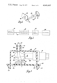
- FIG. 2 is a block diagram of the control system of FIG. 1;
- FIG. 3 is a cross-sectional elevational view of the electro-optic transceiver of FIG. 2;
- FIG. 4 is an exploded view of a portion of the transceiver of FIG. 3;
- FIG. 5 is an optical selector of the system as shown in FIGS. 1 and 2;
- FIG. 6 is a perspective view of a detail of the selector of FIG. 5.
- a vehicle steering column 10 carries a directional signal lever 12 having a selector 14 mounted at the free end thereof.
- the vehicle fire wall 16 carries an electro-optic transceiver 18 and utilization circuitry.
- the transceiver 18 and optical selector 14 are interconnected by a fiber optic light conductor 20 routed internally of the steering column.
- the utilization circuitry associated with the electro-optic transceiver 18 comprises a logic circuit 22 responsive to the output of the transceiver 18 and switch actuators 24 controlled by the circuit 22 for accomplishing the selected switch function.
- the fiber optic light conductor 20 comprises a single bundle of optical fibers enclosed in a jacket of the type that is more fully described in the U.S. Pat. No. to Baer 3,425,581 and is effective to carry light both ways between the selector 14 and the transceiver 18.
- the electro-optic transceiver 18 is shown in FIG. 3 and comprises a molded housing having a flat baseboard 26 with apertures 32 and a hat shaped enclosure portion 28 secured to the baseboard 26 by hook portions 30 extending through apertures 32.
- One wall of the enclosure 28 includes a cylindrical protrusion 34 which receives one end of the light conductor 20 which is encased in a ferrule 36 having a flange 38 engaged in an internal groove 40 of the portion 34.
- a lamp socket 42 extends through an aperture in another wall of the enclosure 28 and supports a lamp 44 within the enclosure.
- a photodetector array 46 is mounted on the baseboard 26 in a position opposite the fiber optic light conductor 20, and an optical filter assembly 48 is located on the surface of the array 46 facing the light conductor 20.
- a complex lens and reflector element 50 occupies the space between the lamp 44, the filter assembly 48 and the light conductor 20 and serves to direct light from the lamp 44 into the end of the light conductor 20 and to direct light from the light conductor 20 to the filter assembly 48 and photodetector array 46.
- the element 50 includes a concave collecting surface 52 adjacent the end of the lamp 44 and a convex reflective surface 54 shaped to focus light from the lamp 44 through an integral convex lens 56 to the light conductor 20.
- the curved surface 54 is interrupted by a lateral projection 58 extending toward the filter assembly 48 which serves to couple light emitted from the light conductor 20 into the filter assembly.
- the projection 58 is shaped and located such that light does not pass directly from the lamp 44 to the filter assembly 48.
- the photodetector array 46 is an integrated circuit module carrying five photodetector elements 60.
- the filter assembly 48 includes five segments 62 each passing a spectral band or combination of bands different from the others so that light impinging on the filter assembly 48 selectively energizes photodetector elements 60 depending upon the particular spectrum of the incident light.
- the optical selector 14 shown in FIGS. 5 and 6 is mounted on the end of the directional signal lever 12 which is tubular.
- the fiber optic conductor 20 extends through the lever 12 into the selector 14.
- the selector 14 comprises an enlarged portion secured to an integral with the lever 12 and has a stationary support 64 having a central bore to receive the light conductor 20 and terminates in a cylindrical wall 66 defining a chamber 68 into which the terminal portion 21 of the light conductor 20 extends.
- the terminal portion 21 is preformed to extend toward one side of the chamber 68 or is resiliently biased into that position by means not shown.
- the housing stationary support 64 includes an outer annular groove 67 surrounding the central bore and has on one side an open pathway to the bore.
- An actuator ring 69 located in the groove has an extension 71 in contact with the light conductor 20 so that upon manual movement of the ring 69, the end of the light conductor 20 is moved from its lateral position within the chamber 68 to a central position aligned with the axis of the assembly.
- a manually rotatable knob 70 is rotatably mounted on the wall 66 and, as shown in FIG. 6, includes a radially inwardly extending web 72 which carries an array of mirrors 74.
- the mirrors comprise a central reflecting element 76 and two radially extending reflectors 78 spaced from a third radially extending reflector 80.
- the outer end of the knob 70 is hollow and supports a push button 82 which is spring biased for linear manual movement axially of the knob 70.
- the push button 82 carries on its innermost surface at least one reflector 84 which lies between the reflectors 78 and 80 on the knob 70.
- Two optional reflectors 86 are also carried by the push button 82 and those reflectors 86 lie radially adjacent the reflectors 78 and 80. Normally, the mirrors 84 and 86 lie somewhat outwardly of the location of the reflector array 74, as shown, but are movable into the region of the array 74 upon actuation of the push button 82.
- Each of the mirrors is coated with a colored filter material such that each individual reflective surface has a unique spectral band or combination of bands so that by selectively positioning the mirrors relative to the end of the light conductor 20, the light carried into the selector is filtered and reflected back into the light conductor 20 where it is carried to the filter array 48.
- red, blue and green bands are selected.
- the reflectors are denoted as R, B, G, RB, RG, etc. denoting red, blue and green or combinations of those colors.
- these colors can be used to relate to accessory switching functions and particularly for windshield wiper/washer and cruise control. These functions are selected for exemplary purposes since they are functions which often are controlled by a mechanism on the directional signal lever.
- the wiper has pulse, slow and fast modes as well as off whereas the wash and cruise control function has one mode each, which are sufficient to initiate the wash or cruise control operation, those functions being ordinarily terminated automatically.
- the table uses binary logic notation to denote the presence or absence of a color band with one or a zero respectively.
- the end of the light conductor When the end of the light conductor is positioned to the side of the chamber 68 as shown in FIG. 5 and the selector is in normal position, the end of the light conductor will be aligned with the space between the reflectors 78 and 80 as seen in FIG. 6 so that no light is reflected back into the light conductor, thereby providing a 000 code which denotes the off mode of the wiper.
- the knob 70 is rotated in one direction, the reflector 80 is positioned opposite the light conductor so that only red light is reflected back into the light conductor. As seen in the table, this denotes the pulse mode of the wiper.
- the knob 70 When the knob 70 is rotated in the other direction from the off position so that either of the reflectors 78 is adjacent the end of the light conductor, either red and blue or red and green codes are selected to indicate slow and fast modes.
- the reflector 84 When the knob is in its normal off position and the cruise control push button 82 is depressed, the reflector 84 is moved to the end of the light conductor and that reflector returns all three color bands to provide the 111 or cruise mode indication.
- the ring 69 To obtain the 011 or wash mode signal, the ring 69 is manually moved to deflect the end of the light conductor 20 to the center of the mirror array aligned with the reflector 76 which carries the blue and green filter.
- the optional reflectors 86 are shown merely to suggest the availability of other control modes.
- the filter assembly 48 When the color coded light signal reaches the transceiver, it is analyzed by the filter assembly 48.
- the individual filters 62 correspond to the filters at the mirror array so that each filter corresponds to one of the color bands or band combinations at the selector.
- the photodetector 60 senses light transmitted through any of the filters and the logic circuit 22 is used to decode the signals and control the actuator 24 in a manner consistent with the coded function request. It is apparent that other codes or other decoding arrangement could be used.
- the code used in the above table could be analyzed with only three filters 62 and photodetectors 60. If red, blue and green filters were used, then the code in the colored light signal could be read to reveal the appropriate function by the logic circuit 22.
- red, blue and green light emitting diodes would comprise the light source and a simple receiver would be responsive to any light pulse received from the selector. The diodes would then be sequentially flashed and reception of a pulse at the receiver would indicate a color the same as that of the sending LED. The logic circuit then would be required to decode the selected switch function in accordance with the pulses received for each set of LED pulses.
Landscapes
- Physics & Mathematics (AREA)
- General Physics & Mathematics (AREA)
- Optics & Photonics (AREA)
- Engineering & Computer Science (AREA)
- Mechanical Engineering (AREA)
- Mechanical Light Control Or Optical Switches (AREA)
- Steering Controls (AREA)
- Switches With Compound Operations (AREA)
- Switch Cases, Indication, And Locking (AREA)
Priority Applications (6)
| Application Number | Priority Date | Filing Date | Title |
|---|---|---|---|
| US05/690,188 US4045667A (en) | 1976-05-26 | 1976-05-26 | Color-sensitive photoelectric control system with fiber optics |
| CA274,958A CA1076675A (en) | 1976-05-26 | 1977-03-29 | Optical multifunction control system for a vehicle |
| DE19772717974 DE2717974A1 (de) | 1976-05-26 | 1977-04-21 | Mehrfunktions-schalteinrichtung fuer kraftfahrzeuge |
| GB17968/77A GB1523999A (en) | 1976-05-26 | 1977-04-29 | Optical multifunction control systems for motor vehicles |
| JP5999777A JPS52145933A (en) | 1976-05-26 | 1977-05-25 | Control system for controlling multiipurpose switch for automobile |
| FR7716130A FR2352683A1 (fr) | 1976-05-26 | 1977-05-26 | Dispositif optique de commande a fonctions multiples pour vehicule a moteur |
Applications Claiming Priority (1)
| Application Number | Priority Date | Filing Date | Title |
|---|---|---|---|
| US05/690,188 US4045667A (en) | 1976-05-26 | 1976-05-26 | Color-sensitive photoelectric control system with fiber optics |
Publications (1)
| Publication Number | Publication Date |
|---|---|
| US4045667A true US4045667A (en) | 1977-08-30 |
Family
ID=24771465
Family Applications (1)
| Application Number | Title | Priority Date | Filing Date |
|---|---|---|---|
| US05/690,188 Expired - Lifetime US4045667A (en) | 1976-05-26 | 1976-05-26 | Color-sensitive photoelectric control system with fiber optics |
Country Status (6)
| Country | Link |
|---|---|
| US (1) | US4045667A (enExample) |
| JP (1) | JPS52145933A (enExample) |
| CA (1) | CA1076675A (enExample) |
| DE (1) | DE2717974A1 (enExample) |
| FR (1) | FR2352683A1 (enExample) |
| GB (1) | GB1523999A (enExample) |
Cited By (21)
| Publication number | Priority date | Publication date | Assignee | Title |
|---|---|---|---|---|
| US4155005A (en) * | 1977-09-08 | 1979-05-15 | Valtec Corporation | Fiber optic control system |
| DE2758698A1 (de) * | 1977-12-29 | 1979-07-05 | Bosch Gmbh Robert | Einrichtung zur abgabe von schaltsignalen in kraftfahrzeugen |
| US4223216A (en) * | 1979-01-22 | 1980-09-16 | Rockwell International Corporation | Means for sensing and color multiplexing optical data over a compact fiber optic transmission system |
| US4281245A (en) * | 1978-06-02 | 1981-07-28 | Asea Aktiebolag | Fiber optical measurement apparatus |
| US4334152A (en) * | 1978-12-06 | 1982-06-08 | Plessey Incorporated | Position indicating systems |
| FR2521081A1 (fr) * | 1982-02-09 | 1983-08-12 | Mitsubishi Electric Corp | Dispositif de commande de vehicule automobile utilisant des capteurs optiques |
| US4445541A (en) * | 1981-07-06 | 1984-05-01 | Dana Corporation | Hydraulic remote control joystick |
| US4456903A (en) * | 1980-03-25 | 1984-06-26 | Nissan Motor Company, Ltd. | Optical signal transmission system for an automotive vehicle |
| EP0147097A3 (en) * | 1983-12-30 | 1985-08-21 | AMP INCORPORATED (a New Jersey corporation) | Fiber optic switching device |
| US4634861A (en) * | 1984-12-19 | 1987-01-06 | General Instrument Corporation | Rotary switch with reflector coded actuator drum |
| US4740688A (en) * | 1986-03-20 | 1988-04-26 | Smiths Industries Public Limited Company | Optical transducers with wavelength coding |
| US4878722A (en) * | 1988-06-24 | 1989-11-07 | Korry Electronics Company | Wavelength encoded optical switches |
| US5073709A (en) * | 1991-04-09 | 1991-12-17 | Graco Inc. | Electrostatic spray applicator with two-channel optical monitoring system |
| EP0591701A3 (enExample) * | 1992-10-08 | 1994-08-03 | Bosch Gmbh Robert | |
| WO1996015470A1 (en) * | 1994-11-16 | 1996-05-23 | Cst Coldswitch Technologies Inc. | Flexible mirror optical switch |
| WO1998014349A1 (de) * | 1996-10-02 | 1998-04-09 | Itt Manufacturing Enterprises, Inc. | Mikroschalteranordnung für bedienelemente von kraftfahrzeugschaltern |
| DE19922500A1 (de) * | 1999-05-15 | 2000-11-16 | Valeo Schalter & Sensoren Gmbh | Modulare Schaltervorrichtung, insbesondere für Kraftahrzeuge |
| WO2001067160A3 (en) * | 2000-03-10 | 2002-01-03 | Tidal Photonics Inc | Apparatus and methods relating to fluorescent optical switches |
| US20050104451A1 (en) * | 2002-02-20 | 2005-05-19 | Georg Poslowsky | Steering device |
| EP2224270A1 (en) | 2009-02-26 | 2010-09-01 | Viacheslav Artyushenko | Fibre optic probe comprising a mode converting fibre |
| EP1673792B1 (de) * | 2003-09-19 | 2011-04-27 | Pepperl + Fuchs GmbH | Vorrichtung zur optischen anzeige von n schaltzuständen |
Families Citing this family (7)
| Publication number | Priority date | Publication date | Assignee | Title |
|---|---|---|---|---|
| CH659149A5 (de) * | 1982-03-29 | 1986-12-31 | Olten Ag Elektro Apparatebau | Schalteinrichtung mit einem schaltteil und einer in einem gehaeuse gelagerten befehls- und meldetaste. |
| GB2117896B (en) * | 1982-04-01 | 1985-06-26 | Standard Telephones Cables Ltd | Optical microswitch system |
| GB2117895A (en) * | 1982-04-01 | 1983-10-19 | Standard Telephones Cables Ltd | Optical microswitch system |
| DE3242978A1 (de) * | 1982-11-20 | 1984-05-24 | Diehl GmbH & Co, 8500 Nürnberg | Fernsteuereinrichtung, insbesondere fuer die steuerung von komfort-einwirkungen im sitz-bereich in der kabine von grossraum-verkehrsflugzeugen |
| US4607161A (en) * | 1983-10-11 | 1986-08-19 | Fiberdynamics, Inc. | Fiberoptic switch system |
| FR2573705B1 (fr) * | 1984-11-27 | 1987-03-20 | Peugeot Aciers Et Outillage | Dispositif de transmission, par couplage optique d'informations issues d'un volant de direction, a un organe solidaire d'un vehicule |
| DE3511839A1 (de) * | 1985-03-30 | 1986-10-02 | Braun Ag, 6000 Frankfurt | Lichtleiter zum beleuchten von geraeteanzeigen |
Citations (2)
| Publication number | Priority date | Publication date | Assignee | Title |
|---|---|---|---|---|
| US2806402A (en) * | 1954-10-04 | 1957-09-17 | Gen Motors Corp | Propeller blade angle indicating device |
| US3886544A (en) * | 1974-06-12 | 1975-05-27 | Leo H Narodny | Keyboard using optical switching |
Family Cites Families (4)
| Publication number | Priority date | Publication date | Assignee | Title |
|---|---|---|---|---|
| DE1763028A1 (de) * | 1968-03-25 | 1971-08-19 | Lothar Sachsse | Fernsteuereinrichtung fuer bewegliche Geraete,insbesondere fuer Spielzeugfahrzeuge |
| DE7129942U (de) * | 1971-08-04 | 1971-12-02 | Gillich H | Schalter |
| US4023887A (en) * | 1972-10-30 | 1977-05-17 | General Optimation, Inc. | Optical communication, switching and control apparatus and systems and modular electro-optical logic circuits, and applications thereof |
| JPS5438769B2 (enExample) * | 1974-09-30 | 1979-11-22 |
-
1976
- 1976-05-26 US US05/690,188 patent/US4045667A/en not_active Expired - Lifetime
-
1977
- 1977-03-29 CA CA274,958A patent/CA1076675A/en not_active Expired
- 1977-04-21 DE DE19772717974 patent/DE2717974A1/de not_active Withdrawn
- 1977-04-29 GB GB17968/77A patent/GB1523999A/en not_active Expired
- 1977-05-25 JP JP5999777A patent/JPS52145933A/ja active Pending
- 1977-05-26 FR FR7716130A patent/FR2352683A1/fr active Granted
Patent Citations (2)
| Publication number | Priority date | Publication date | Assignee | Title |
|---|---|---|---|---|
| US2806402A (en) * | 1954-10-04 | 1957-09-17 | Gen Motors Corp | Propeller blade angle indicating device |
| US3886544A (en) * | 1974-06-12 | 1975-05-27 | Leo H Narodny | Keyboard using optical switching |
Cited By (25)
| Publication number | Priority date | Publication date | Assignee | Title |
|---|---|---|---|---|
| US4155005A (en) * | 1977-09-08 | 1979-05-15 | Valtec Corporation | Fiber optic control system |
| DE2758698A1 (de) * | 1977-12-29 | 1979-07-05 | Bosch Gmbh Robert | Einrichtung zur abgabe von schaltsignalen in kraftfahrzeugen |
| US4281245A (en) * | 1978-06-02 | 1981-07-28 | Asea Aktiebolag | Fiber optical measurement apparatus |
| US4334152A (en) * | 1978-12-06 | 1982-06-08 | Plessey Incorporated | Position indicating systems |
| US4223216A (en) * | 1979-01-22 | 1980-09-16 | Rockwell International Corporation | Means for sensing and color multiplexing optical data over a compact fiber optic transmission system |
| US4456903A (en) * | 1980-03-25 | 1984-06-26 | Nissan Motor Company, Ltd. | Optical signal transmission system for an automotive vehicle |
| US4445541A (en) * | 1981-07-06 | 1984-05-01 | Dana Corporation | Hydraulic remote control joystick |
| FR2521081A1 (fr) * | 1982-02-09 | 1983-08-12 | Mitsubishi Electric Corp | Dispositif de commande de vehicule automobile utilisant des capteurs optiques |
| EP0147097A3 (en) * | 1983-12-30 | 1985-08-21 | AMP INCORPORATED (a New Jersey corporation) | Fiber optic switching device |
| US4634861A (en) * | 1984-12-19 | 1987-01-06 | General Instrument Corporation | Rotary switch with reflector coded actuator drum |
| US4740688A (en) * | 1986-03-20 | 1988-04-26 | Smiths Industries Public Limited Company | Optical transducers with wavelength coding |
| US4878722A (en) * | 1988-06-24 | 1989-11-07 | Korry Electronics Company | Wavelength encoded optical switches |
| US5073709A (en) * | 1991-04-09 | 1991-12-17 | Graco Inc. | Electrostatic spray applicator with two-channel optical monitoring system |
| EP0591701A3 (enExample) * | 1992-10-08 | 1994-08-03 | Bosch Gmbh Robert | |
| WO1996015470A1 (en) * | 1994-11-16 | 1996-05-23 | Cst Coldswitch Technologies Inc. | Flexible mirror optical switch |
| US5892862A (en) * | 1994-11-16 | 1999-04-06 | Kidder; John S. | Flexible mirror optical switch |
| WO1998014349A1 (de) * | 1996-10-02 | 1998-04-09 | Itt Manufacturing Enterprises, Inc. | Mikroschalteranordnung für bedienelemente von kraftfahrzeugschaltern |
| DE19922500A1 (de) * | 1999-05-15 | 2000-11-16 | Valeo Schalter & Sensoren Gmbh | Modulare Schaltervorrichtung, insbesondere für Kraftahrzeuge |
| DE19922500B4 (de) * | 1999-05-15 | 2005-12-15 | Valeo Schalter Und Sensoren Gmbh | Modulare Schaltervorrichtung, insbesondere für Kraftahrzeuge |
| WO2001067160A3 (en) * | 2000-03-10 | 2002-01-03 | Tidal Photonics Inc | Apparatus and methods relating to fluorescent optical switches |
| US6721471B2 (en) | 2000-03-10 | 2004-04-13 | Tidal Photonics, Inc. | Apparatus and methods relating to fluorescent optical switches |
| US20050104451A1 (en) * | 2002-02-20 | 2005-05-19 | Georg Poslowsky | Steering device |
| US7078718B2 (en) * | 2002-02-20 | 2006-07-18 | Valeo Schelter Und Sensoren Gmbh | Steering device using optical signal transmission |
| EP1673792B1 (de) * | 2003-09-19 | 2011-04-27 | Pepperl + Fuchs GmbH | Vorrichtung zur optischen anzeige von n schaltzuständen |
| EP2224270A1 (en) | 2009-02-26 | 2010-09-01 | Viacheslav Artyushenko | Fibre optic probe comprising a mode converting fibre |
Also Published As
| Publication number | Publication date |
|---|---|
| DE2717974A1 (de) | 1977-12-08 |
| GB1523999A (en) | 1978-09-06 |
| FR2352683B1 (enExample) | 1983-06-10 |
| CA1076675A (en) | 1980-04-29 |
| JPS52145933A (en) | 1977-12-05 |
| FR2352683A1 (fr) | 1977-12-23 |
Similar Documents
| Publication | Publication Date | Title |
|---|---|---|
| US4045667A (en) | Color-sensitive photoelectric control system with fiber optics | |
| US5347123A (en) | Optical control switch device having a plurality of light receptors | |
| US6102559A (en) | Multi-function vehicle taillight system with unitary optic | |
| JP2740983B2 (ja) | 照明付き雨がさまたは日がさ | |
| US4609976A (en) | Combination flashlight and warning light | |
| US6344846B1 (en) | Optical retroreflective remote control | |
| US6111563A (en) | Cordless retroreflective optical computer mouse | |
| US5056821A (en) | Illuminated ski pole and method | |
| US5046806A (en) | Single fibre control switches | |
| US5090791A (en) | Self-illuminated fibre optic switch | |
| US4556280A (en) | Single cable optical fibre signaling system | |
| JP5180768B2 (ja) | ダイヤル式スイッチ | |
| EP0889351A4 (en) | PROJECTION SCREEN AND OPTICAL LIGHTING SYSTEM DAFUR | |
| US5892862A (en) | Flexible mirror optical switch | |
| KR20010095313A (ko) | 발광장치 및 그 작동방법 | |
| WO2002018993A3 (en) | Tunable optical filter with retained complementary output | |
| US6685336B1 (en) | Light emitting diode (LED) flashlight | |
| US5780795A (en) | Contactless switching and encoding | |
| US7086759B2 (en) | Decorative lamp | |
| US3705983A (en) | Flashlight | |
| US4678906A (en) | Device for transmitting through an optical coupling data issuing from a steering wheel to an element mounted on a vehicle | |
| DE69031035D1 (de) | Funkgerät mit optischer steuerung | |
| US6297896B1 (en) | Optical switch and optical communication system using the same | |
| CA2056850A1 (en) | Optical sensor | |
| US20040144914A1 (en) | Device for the optoelectronic detection of switching positions of a switching element |