US3652067A - Furnace for heating bars, tubes or similar oblong articles - Google Patents
Furnace for heating bars, tubes or similar oblong articles Download PDFInfo
- Publication number
- US3652067A US3652067A US39036A US3652067DA US3652067A US 3652067 A US3652067 A US 3652067A US 39036 A US39036 A US 39036A US 3652067D A US3652067D A US 3652067DA US 3652067 A US3652067 A US 3652067A
- Authority
- US
- United States
- Prior art keywords
- heating chamber
- articles
- furnace
- furnace according
- heated
- Prior art date
- Legal status (The legal status is an assumption and is not a legal conclusion. Google has not performed a legal analysis and makes no representation as to the accuracy of the status listed.)
- Expired - Lifetime
Links
Images


Classifications
-
- C—CHEMISTRY; METALLURGY
- C21—METALLURGY OF IRON
- C21D—MODIFYING THE PHYSICAL STRUCTURE OF FERROUS METALS; GENERAL DEVICES FOR HEAT TREATMENT OF FERROUS OR NON-FERROUS METALS OR ALLOYS; MAKING METAL MALLEABLE, e.g. BY DECARBURISATION OR TEMPERING
- C21D9/00—Heat treatment, e.g. annealing, hardening, quenching or tempering, adapted for particular articles; Furnaces therefor
- C21D9/0075—Heat treatment, e.g. annealing, hardening, quenching or tempering, adapted for particular articles; Furnaces therefor for rods of limited length
Definitions
- Said furnaces comprise a steel jacket in which a brickwork of refractory bricks is provided forming the so called furnace chamber.
- the articles to be heated are position in said furnace chamber into which burners for liquid or gaseous fuel discharge.
- An exhaust for combustion gases is provided and also supply means and discharge means for the articles to be heated.
- the present invention relates to a furnace for heating bars, tubes or similar oblong articles, comprising a heating chamber having the length of the articles to be heated, burners for liquid or gaseous fuel discharging into said heating chamber, an exhaust for the combustion gases, a supply and a discharge means for the articles to be heated and the heated articles.
- Such furnaces are known. They serve for preparing material that must be pressed or forged, and comprise a steel jacket in which a brickwork of refractory bricks is provided forming the so-called furnace chamber.
- the articles to be heated are positioned in said furnace chamber into which the burners discharge. Said articles are lengthwise conveyed into said furnace chamber.
- the length of the furnace must be at least equal to the length of the longest article to be treated.
- the cross section of the furnace chamber is relatively small, such that only a few articles can be heated into the chamber. It is useless to increase said cross section since the articles must not be heated too long otherwise they will burn and too much scale will be formed.
- the object of the present invention is to provide a furnace in which the above-mentioned disadvantages are eliminated.
- the discharge means for the exhaust gases is provided sideways and lengthwise to the heating chamber and is carried out as a slot or passageway through which the supply of the oblong articles takes place transversely to their length, such that the preheating of the articles takes place by convection and the proper heating by radiation.
- the heating chamber has such a cross section, e.g., a circular cross section, that one oblong article can be heated at a time.
- the bottom of the heating chamber is provided with sliding blocks or the like for supporting the articles to be pushed lengthwise through and from the heating chamber.
- the burners In order to increase the efficiency the burners extend tangentially into the heating chamber.
- rotatable endless screws are provided for supplying the oblong articles to the heating chamber, said screws extending transversely into the gas exhaust slot.
- said rotatable screws are internally air cooled.
- the furnace is composed of sections of refractory material positioned lengthwise adjacent to each other.
- each section consists of two superimposed elements, each containing a portion of the heating chamber.
- An embodiment of the furnace for heating bars according to the invention is shown by way of example.
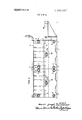
- FIG. 1 shows a plan view of two adjacent furnace sections.
- FIG. 2 shows a cross section of two adjacent furnace sections along the line IIIl in FIG. 3, the supply device for the bars being omitted.
- FIG. 3 shows a cross section along the line III-Ill in FIG. 1.
- FIG. 4 shows a longitudinal section of two furnace sections.
- each section consists of a bottom-frame 2 and an upper frame 3, the bottom-frame being provided at its bottom with recesses 4 such that said sections easily can be moved e.g., by means of lifting machine.
- dish springs 7 In order to compensate the expansion that is created by heating the furnace and to maintain said pretension as constant as possible dish springs 7 are provided.
- the upper frame and the bottom-frame are made of cast or rammed refractory concrete, however, said frame could be made of burned refractory ceramic material. Both frames are pretensioned by means of draw bars 8 and pressing plates 9, dished springs 10 being provided in order to keep the pretensioning forces as constant as possible.
- the furnace has a hollow interior 11, forming the heating chamber.
- a number of burners 12 discharge tangentially into said chamber, said burners being mounted in the upper frame 3. Said burners are interconnected with a main fuel conduit 14 through lines 13, said main fuel conduit 14 extending over the whole length of the furnace, but being detachable by means of couplings 15 between adjacent furnace sections.
- the exhaust gases leave the heating chamber 11 through the slot 16in which the bars to be supplied are kept and which extends transversely over the whole length of the furnace. Since said slot 16 only has a relatively small width the exhaust gases will have a vortex motion such that they will wash the bars and transfers their heat to them, said bars being conveyed to the heating chamber 11 in a well preheated condition. Since the exhaust from the furnace gases in their way to the exhaust encounter bars in a colder state, the temperature of said gases will decrease in a steady way and at the time they leave the furnace their temperature will be a fraction only of the temperature they had when leaving the heating chamber and entering the slot.
- the bars are supplied through the slot 16 by means of rotatable screws 17a, b which are internally air cooled and are rotatable in bearings 18. Said screws 17a, b one of which being provided in each section, are mounted in such a way that one or two rotating clockwise are positioned adjacent to one or two rotating anticlockwise which prevents that the bars are shifted lengthwise.
- the screws receive a continuous rotation by means of an electromotor 19 through a transmission 20.
- the shafts of transmission 20 are provided with sprockets, the shown 21 of which drives the sprocket 23 on the clockwise rotating screw 17b and the invisible sprocket 22 drives the sprocket 24 on the anticlockwise rotating screw 17a.
- the sprockets 25 and 27 drive the screws of other sections, if any, of the furnace.
- the bars to be supplied are received by the screws 17a and 17b through a pneumatically driven supply mechanism.
- the bars 40 are supported by supporting means 29 (vide HO. 3), said means being provided with upturned edges 30.
- the air cylinder 31 receives an impulse so that the piston rod 26 of said cylinder will move inwardly and the shaft 32 will be rotated clockwise by means of the arm 33 fixed to said shaft 32.
- the lever 34 which is also attached to the shaft 32 will rotate upwardly and will cause the plate 35 linked to the lever 34 and guided by the pin 36 to raise such that the cam 37 attached to the plate 35 will push a bar over the upturned ridge of the supports 29 said bar being placed onto the screws and guided into the furnace.
- another air cylinder 38 is provided. Said air cylinder 38 pushes at the right time a bar out of the heating chamber 11 in a machine for a further treatment. Since the heated bar performs a sliding movement in the heating chamber 11 sliding blocks 39 are provided in said chamber in order to prevent damaging of the bars, said blocks being interchangeable in an easy way.
- a furnace for heating bars, tubes and similar elongated articles comprising a heating chamber for heating said articles, said chamber having the length of the articles to be heated, fuel burners for discharging hot combustion gases into said heating chamber, an exhaust passageway for conducting the combustion gases from the heating chamber, means for supplying the articles to be heated into the heating chamber, and means for discharging the heated articles from the heating chamber, wherein the exhaust passageway for the combustion gases is located alongside and extends lengthwise of the elongated heating chamber, and wherein the means for supplying the articles to be heated to the heating chamber includes means for delivering them into the exhaust gas passageway to move transversely therethrough in contact with hot gases flowing therethrough and then into the heating chamber.
- a furnace according to claim I wherein the means for supplying the elongated articles to the heating chamber through the gas exhaust passageway comprise rotatable screws extending transversely to the gas exhaust passageway.
- a furnace according to claim 4 including means for rotating adjacent screws alternately clockwise and anticlockwise.
- a furnace according to claim 1 comprised of lengthwisepositioned sections of refractory material.
- each section is comprised of two superimposed elements, each containing a portion of the heating chamber.
- a furnace according to claim 8 wherein the two elements are pulled against each other by means of draw bars.
- a furnace according to claim 1, wherein the means for supplying the articles to the heating chamber include means for delivering the articles one at a time to the means for delivering them into and through the exhaust gas passageway to the heating chamber.
Landscapes
- Chemical & Material Sciences (AREA)
- Engineering & Computer Science (AREA)
- Materials Engineering (AREA)
- Thermal Sciences (AREA)
- Crystallography & Structural Chemistry (AREA)
- Mechanical Engineering (AREA)
- Physics & Mathematics (AREA)
- Metallurgy (AREA)
- Organic Chemistry (AREA)
- Tunnel Furnaces (AREA)
- Forging (AREA)
- Heat Treatments In General, Especially Conveying And Cooling (AREA)
- Vertical, Hearth, Or Arc Furnaces (AREA)
- Furnace Details (AREA)
- Heat Treatment Of Articles (AREA)
Applications Claiming Priority (1)
| Application Number | Priority Date | Filing Date | Title |
|---|---|---|---|
| NL696907877A NL140012B (nl) | 1969-05-22 | 1969-05-22 | Oven voor het verhitten van staven, buizen of dergelijke langwerpige voorwerpen. |
Publications (1)
| Publication Number | Publication Date |
|---|---|
| US3652067A true US3652067A (en) | 1972-03-28 |
Family
ID=19806993
Family Applications (1)
| Application Number | Title | Priority Date | Filing Date |
|---|---|---|---|
| US39036A Expired - Lifetime US3652067A (en) | 1969-05-22 | 1970-05-20 | Furnace for heating bars, tubes or similar oblong articles |
Country Status (15)
| Country | Link |
|---|---|
| US (1) | US3652067A (de) |
| AT (1) | AT300003B (de) |
| BE (1) | BE750519A (de) |
| CH (1) | CH510120A (de) |
| CS (1) | CS166726B2 (de) |
| DE (1) | DE2024852B2 (de) |
| ES (1) | ES379894A1 (de) |
| FR (1) | FR2049115B1 (de) |
| GB (1) | GB1245230A (de) |
| HU (1) | HU166459B (de) |
| IE (1) | IE34173B1 (de) |
| NL (2) | NL140012B (de) |
| NO (1) | NO133093C (de) |
| PL (1) | PL71522B1 (de) |
| SE (1) | SE351237B (de) |
Families Citing this family (1)
| Publication number | Priority date | Publication date | Assignee | Title |
|---|---|---|---|---|
| WO2015128796A1 (en) | 2014-02-25 | 2015-09-03 | Tenova S.P.A. | Auger conveyor assembly for transporting elongated articles of the bar type, pipe type or the like, conveyor appliance for transporting elongated articles of the bar type, pipe tyre or the like comprising such auger conveyor assembly and plant for heat treatment of elongated articles of the bar type, pipe type or the like comprising such a conveyor appliance |
Citations (2)
| Publication number | Priority date | Publication date | Assignee | Title |
|---|---|---|---|---|
| US2371335A (en) * | 1943-11-30 | 1945-03-13 | Nat Tube Co | Rotary heating furnace |
| US2930599A (en) * | 1958-01-20 | 1960-03-29 | Midland Ross Corp | Apparatus for heating metal work |
-
1969
- 1969-05-22 NL NL696907877A patent/NL140012B/xx unknown
-
1970
- 1970-05-15 SE SE06779/70A patent/SE351237B/xx unknown
- 1970-05-15 BE BE750519D patent/BE750519A/xx unknown
- 1970-05-18 IE IE652/70A patent/IE34173B1/xx unknown
- 1970-05-19 NO NO1896/70A patent/NO133093C/no unknown
- 1970-05-20 US US39036A patent/US3652067A/en not_active Expired - Lifetime
- 1970-05-20 PL PL1970140747A patent/PL71522B1/pl unknown
- 1970-05-21 ES ES379894A patent/ES379894A1/es not_active Expired
- 1970-05-21 CS CS3559A patent/CS166726B2/cs unknown
- 1970-05-21 CH CH756170A patent/CH510120A/de not_active IP Right Cessation
- 1970-05-21 AT AT456670A patent/AT300003B/de not_active IP Right Cessation
- 1970-05-21 DE DE19702024852 patent/DE2024852B2/de not_active Withdrawn
- 1970-05-21 HU HUNE467A patent/HU166459B/hu unknown
- 1970-05-21 GB GB24574/70A patent/GB1245230A/en not_active Expired
- 1970-05-22 FR FR707018816A patent/FR2049115B1/fr not_active Expired
-
1972
- 1972-01-21 NL NL727200869A patent/NL148942B/xx unknown
Patent Citations (2)
| Publication number | Priority date | Publication date | Assignee | Title |
|---|---|---|---|---|
| US2371335A (en) * | 1943-11-30 | 1945-03-13 | Nat Tube Co | Rotary heating furnace |
| US2930599A (en) * | 1958-01-20 | 1960-03-29 | Midland Ross Corp | Apparatus for heating metal work |
Also Published As
| Publication number | Publication date |
|---|---|
| IE34173B1 (en) | 1975-02-19 |
| PL71522B1 (de) | 1974-06-29 |
| HU166459B (de) | 1975-03-28 |
| NL148942B (nl) | 1976-03-15 |
| FR2049115B1 (de) | 1973-07-13 |
| CH510120A (de) | 1971-07-15 |
| NL6907877A (de) | 1970-11-24 |
| IE34173L (en) | 1970-11-22 |
| AT300003B (de) | 1972-07-10 |
| ES379894A1 (es) | 1973-02-16 |
| NO133093C (de) | 1976-03-10 |
| NO133093B (de) | 1975-12-01 |
| DE2024852B2 (de) | 1972-01-27 |
| BE750519A (fr) | 1970-10-16 |
| NL140012B (nl) | 1973-10-15 |
| FR2049115A1 (de) | 1971-03-26 |
| SE351237B (de) | 1972-11-20 |
| CS166726B2 (de) | 1976-03-29 |
| NL7200869A (en) | 1972-04-25 |
| DE2024852A1 (de) | 1970-12-17 |
| GB1245230A (en) | 1971-09-08 |
Similar Documents
| Publication | Publication Date | Title |
|---|---|---|
| JPS5880488A (ja) | 二重傾斜炉 | |
| US3652067A (en) | Furnace for heating bars, tubes or similar oblong articles | |
| US1889511A (en) | Rotary glass melting furnace | |
| GB1473034A (en) | Burning of pulverous or granular raw materials | |
| GB1414619A (en) | Heat treatment furnaces and methods of heat treatment | |
| GB1254360A (en) | Improvements in continuous heating furnaces | |
| US4664359A (en) | Furnace for heat treating light alloy ingots | |
| RU2005138286A (ru) | Способ обжига кусков материала, в частности, известняка | |
| US1400367A (en) | Furnace and method of conveying materials therethrough | |
| US3542349A (en) | Radiation-type heating furnace with atmosphere regulation | |
| US1940554A (en) | Method and apparatus for manufacturing ceramic bodies | |
| CN202002465U (zh) | 一种绝热陶瓷饰面砖烧成辊道窑 | |
| US1285750A (en) | Apparatus for treating steel rails. | |
| ES451479A1 (es) | Un horno tunel para cocer material ceramico. | |
| KR100851210B1 (ko) | 가열로의 슬라브 이송 장치 | |
| US2496914A (en) | Heating furnace | |
| US1941599A (en) | Conveyer type of pair or pack furnace | |
| US1891919A (en) | Enameling furnace | |
| US2534021A (en) | Heating apparatus for heating ends of elongated workpieces in a continuous process | |
| FR2369228A1 (fr) | Four a longueur variable pour la cuisson en monocouche de produits ceramiques | |
| SU402947A1 (ru) | Печь для термообработки ферритовых изделий | |
| US888815A (en) | Furnace. | |
| US1028685A (en) | Method of saving heat. | |
| US2930599A (en) | Apparatus for heating metal work | |
| KR20080043516A (ko) | 생석회 제조장치 및 방법 |