US3483055A - Method for forming a fiber glass racket frame - Google Patents
Method for forming a fiber glass racket frame Download PDFInfo
- Publication number
- US3483055A US3483055A US537898A US3483055DA US3483055A US 3483055 A US3483055 A US 3483055A US 537898 A US537898 A US 537898A US 3483055D A US3483055D A US 3483055DA US 3483055 A US3483055 A US 3483055A
- Authority
- US
- United States
- Prior art keywords
- mandrel
- frame
- racket
- loop
- mold
- Prior art date
- Legal status (The legal status is an assumption and is not a legal conclusion. Google has not performed a legal analysis and makes no representation as to the accuracy of the status listed.)
- Expired - Lifetime
Links
- 238000000034 method Methods 0.000 title description 34
- 239000011152 fibreglass Substances 0.000 title description 16
- 239000000463 material Substances 0.000 description 63
- 238000001723 curing Methods 0.000 description 15
- 239000011521 glass Substances 0.000 description 11
- 238000004519 manufacturing process Methods 0.000 description 10
- 239000003795 chemical substances by application Substances 0.000 description 9
- 239000011888 foil Substances 0.000 description 9
- 230000002745 absorbent Effects 0.000 description 8
- 239000002250 absorbent Substances 0.000 description 8
- 239000000853 adhesive Substances 0.000 description 7
- 230000001070 adhesive effect Effects 0.000 description 7
- 230000009975 flexible effect Effects 0.000 description 7
- 238000004804 winding Methods 0.000 description 6
- 239000000049 pigment Substances 0.000 description 5
- 229920005989 resin Polymers 0.000 description 4
- 239000011347 resin Substances 0.000 description 4
- 125000006850 spacer group Chemical group 0.000 description 4
- 239000004744 fabric Substances 0.000 description 3
- 238000003825 pressing Methods 0.000 description 3
- 239000003822 epoxy resin Substances 0.000 description 2
- 238000013007 heat curing Methods 0.000 description 2
- 238000010438 heat treatment Methods 0.000 description 2
- 239000004033 plastic Substances 0.000 description 2
- 239000002984 plastic foam Substances 0.000 description 2
- 229920000647 polyepoxide Polymers 0.000 description 2
- 239000000126 substance Substances 0.000 description 2
- 239000002023 wood Substances 0.000 description 2
- 230000037303 wrinkles Effects 0.000 description 2
- 241000771208 Buchanania arborescens Species 0.000 description 1
- 235000009854 Cucurbita moschata Nutrition 0.000 description 1
- 240000001980 Cucurbita pepo Species 0.000 description 1
- 235000009852 Cucurbita pepo Nutrition 0.000 description 1
- 239000004677 Nylon Substances 0.000 description 1
- 150000001412 amines Chemical class 0.000 description 1
- 239000010425 asbestos Substances 0.000 description 1
- 230000004888 barrier function Effects 0.000 description 1
- 239000001913 cellulose Substances 0.000 description 1
- 229920002678 cellulose Polymers 0.000 description 1
- 239000011248 coating agent Substances 0.000 description 1
- 238000000576 coating method Methods 0.000 description 1
- 230000002860 competitive effect Effects 0.000 description 1
- 239000002131 composite material Substances 0.000 description 1
- 238000010276 construction Methods 0.000 description 1
- 238000005520 cutting process Methods 0.000 description 1
- 238000009826 distribution Methods 0.000 description 1
- 238000005553 drilling Methods 0.000 description 1
- 230000000694 effects Effects 0.000 description 1
- 238000005562 fading Methods 0.000 description 1
- 239000000945 filler Substances 0.000 description 1
- 239000012530 fluid Substances 0.000 description 1
- 239000002184 metal Substances 0.000 description 1
- 239000000203 mixture Substances 0.000 description 1
- 229920001778 nylon Polymers 0.000 description 1
- 230000002093 peripheral effect Effects 0.000 description 1
- 238000005498 polishing Methods 0.000 description 1
- 229920001225 polyester resin Polymers 0.000 description 1
- 239000004645 polyester resin Substances 0.000 description 1
- 238000006116 polymerization reaction Methods 0.000 description 1
- 238000011417 postcuring Methods 0.000 description 1
- 239000001054 red pigment Substances 0.000 description 1
- 229910052895 riebeckite Inorganic materials 0.000 description 1
- 238000005507 spraying Methods 0.000 description 1
- 235000020354 squash Nutrition 0.000 description 1
- 229920001187 thermosetting polymer Polymers 0.000 description 1
- 238000011282 treatment Methods 0.000 description 1
- 239000002966 varnish Substances 0.000 description 1
Images


Classifications
-
- A—HUMAN NECESSITIES
- A63—SPORTS; GAMES; AMUSEMENTS
- A63B—APPARATUS FOR PHYSICAL TRAINING, GYMNASTICS, SWIMMING, CLIMBING, OR FENCING; BALL GAMES; TRAINING EQUIPMENT
- A63B49/00—Stringed rackets, e.g. for tennis
- A63B49/02—Frames
- A63B49/10—Frames made of non-metallic materials, other than wood
-
- A—HUMAN NECESSITIES
- A63—SPORTS; GAMES; AMUSEMENTS
- A63B—APPARATUS FOR PHYSICAL TRAINING, GYMNASTICS, SWIMMING, CLIMBING, OR FENCING; BALL GAMES; TRAINING EQUIPMENT
- A63B60/00—Details or accessories of golf clubs, bats, rackets or the like
-
- B—PERFORMING OPERATIONS; TRANSPORTING
- B29—WORKING OF PLASTICS; WORKING OF SUBSTANCES IN A PLASTIC STATE IN GENERAL
- B29C—SHAPING OR JOINING OF PLASTICS; SHAPING OF MATERIAL IN A PLASTIC STATE, NOT OTHERWISE PROVIDED FOR; AFTER-TREATMENT OF THE SHAPED PRODUCTS, e.g. REPAIRING
- B29C70/00—Shaping composites, i.e. plastics material comprising reinforcements, fillers or preformed parts, e.g. inserts
- B29C70/04—Shaping composites, i.e. plastics material comprising reinforcements, fillers or preformed parts, e.g. inserts comprising reinforcements only, e.g. self-reinforcing plastics
- B29C70/06—Fibrous reinforcements only
- B29C70/10—Fibrous reinforcements only characterised by the structure of fibrous reinforcements, e.g. hollow fibres
- B29C70/16—Fibrous reinforcements only characterised by the structure of fibrous reinforcements, e.g. hollow fibres using fibres of substantial or continuous length
- B29C70/20—Fibrous reinforcements only characterised by the structure of fibrous reinforcements, e.g. hollow fibres using fibres of substantial or continuous length oriented in a single direction, e.g. roofing or other parallel fibres
-
- A—HUMAN NECESSITIES
- A63—SPORTS; GAMES; AMUSEMENTS
- A63B—APPARATUS FOR PHYSICAL TRAINING, GYMNASTICS, SWIMMING, CLIMBING, OR FENCING; BALL GAMES; TRAINING EQUIPMENT
- A63B2209/00—Characteristics of used materials
- A63B2209/02—Characteristics of used materials with reinforcing fibres, e.g. carbon, polyamide fibres
- A63B2209/023—Long, oriented fibres, e.g. wound filaments, woven fabrics, mats
-
- A—HUMAN NECESSITIES
- A63—SPORTS; GAMES; AMUSEMENTS
- A63B—APPARATUS FOR PHYSICAL TRAINING, GYMNASTICS, SWIMMING, CLIMBING, OR FENCING; BALL GAMES; TRAINING EQUIPMENT
- A63B60/00—Details or accessories of golf clubs, bats, rackets or the like
- A63B60/06—Handles
-
- A—HUMAN NECESSITIES
- A63—SPORTS; GAMES; AMUSEMENTS
- A63B—APPARATUS FOR PHYSICAL TRAINING, GYMNASTICS, SWIMMING, CLIMBING, OR FENCING; BALL GAMES; TRAINING EQUIPMENT
- A63B60/00—Details or accessories of golf clubs, bats, rackets or the like
- A63B60/52—Details or accessories of golf clubs, bats, rackets or the like with slits
-
- Y—GENERAL TAGGING OF NEW TECHNOLOGICAL DEVELOPMENTS; GENERAL TAGGING OF CROSS-SECTIONAL TECHNOLOGIES SPANNING OVER SEVERAL SECTIONS OF THE IPC; TECHNICAL SUBJECTS COVERED BY FORMER USPC CROSS-REFERENCE ART COLLECTIONS [XRACs] AND DIGESTS
- Y10—TECHNICAL SUBJECTS COVERED BY FORMER USPC
- Y10S—TECHNICAL SUBJECTS COVERED BY FORMER USPC CROSS-REFERENCE ART COLLECTIONS [XRACs] AND DIGESTS
- Y10S273/00—Amusement devices: games
- Y10S273/07—Glass fiber
Definitions
- This invention relates to a fiber glass racket frame and, more particularly, to a fiber glass racket frame which enables the user to control the flight of a tennis ball or the like with a maximum uniformity and minimum effort for a long period of time.
- an object of this invention to provide a fiber glass racket frame which exhibits a greater strength than the wooden racket frames; a greater fatigue life; a
- the present invention features a racket frame formed by a mold which consists of several component parts, including a front and back plate, a pair of clamping members, a pair of flanged arcuate arms, and a mandrel shaped according to the desired shape of the finished racket frame.
- a mold which consists of several component parts, including a front and back plate, a pair of clamping members, a pair of flanged arcuate arms, and a mandrel shaped according to the desired shape of the finished racket frame.
- an inner loop or ring of uncured, substantially fiber glass, heat curable, flexible material is wound or placed over the mandrel between the two side plates and an outer loop or ring of the same material as above, but of a considerably larger diameter is wound or placed over the inner material in an abutting relation, the lower portion of the outer material hanging down to the bottom of the mold.
- a pair of clamping members are then clamped over this lower portion of the outer material to form the frame handle and the mold itself is secured together.
- the inner material together with the upper portion of the outer material forms the frame head, and the flanged arcuate arms may then be pivoted downwardly over this head to form a groove along the head to aid in the subsequent stringing of the frame.
- the materials are then cured in the mold to form a. single racket frame which is then subjected to several finishing treatments.
- an elongated stock piece which is substantially thicker than the normal width of the average racket is formed and subsequently sliced into a plurality of individual rackets.
- the apparatus for forming this stock piece includes an elongated lower mandrel about which an inner loop of substantially fiber glass heat curable, flexible material of considerable width is wound or placed, preferably in a helical manner. Also provided is a rod extending parallel to the lower mandrel; and an outer loop of a similar material is wound or placed around the rod and mandrel with the upper portion of each material being in an abutting relationship over the upper portion of the mandrel. The rod is then moved in a direction away from the lower mandrel to stretch the lower portion of the outer material.
- a pair of clamping members are then clamped between the rod and the mandrel which forms a portion of the outer material into the frame handle.
- a pair of arms substantially similar to those discussed above may then be utilized to form the grooves in the racket heads.
- the stock piece is removed from the mold after curing and then sliced in a direction so that a plurality of individual frames are formed.
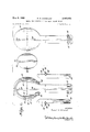
- FIG. 1 is a plan view of the major components for forming a single racket frame according to the subject invention
- FIG. 2 is a plan view illustrating the preliminary step in the assembling of the mold and the forming of the racket frame
- FIG. 3 is a plan view with the mold assembled, but with the front plate omitted for the sake of clarity;
- FIG. 4 is a side elevation of the assembled mold
- FIGS. 5 and 6 are sectional views taken along lines 55 and 6-6 respectively of FIG. 3;
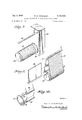
- FIG. 7 is a sectional view of a typical ply of the racket frame taken along line 7-7 of FIG. 2;
- FIG. 8 is aperspective view of an apparatus used in the forming of a stock piece from which' a plurality of rackets may be formed, showing the inner ring which forms a portion of the racket head wrapped about a lower mandrel;
- FIG. 9 is a fragmentary perspective view of the device of FIG. 8 showing a further step in the assembly of a stock piece from which a plurality of frames may be formed;
- FIG. 10 is a perspective view of a device for ejecting the finished stock piece from the apparatus of FIGS. 8 and 9;
- FIG. 11 is a perspective view showing the arrangement of FIGS. 8 and 9 during the step of curing the stock piece
- FIG. 12 is a side elevation of the stock piece being ejected from the machine
- FIG. 13 is a side elevation of a completed stock piece with phantom lines indicating lines through which the stock piece may be cut to form separate racket frames.
- a mold 10 which is formed of various component parts, including a back plate 12, an elliptical shaped mandrel 16 and a front plate 14. Also provided are a pair of clamping members 18 and 20 and a center piece 22 which does not form a portion of the mold, but rather is included in the final cured racket frame. After the materials to be cured are placed in the mold in a manner to be discussed in detail later, the mold is tightened, the means for effecting this being seen by a reference to FIG. 4. As shown, back plate 12 and front plate 14 each have a plurality of holes 24 through which is inserted bolts 26. Mandrel 16, which is inserted between the plates, also is provided with holes 24 through which the bolts 26 extend. Nuts 28 are then tightened over the bolts 26 in order to lock the parts together.
- Clamping members 18 and 20 are provided to form the frame handle and are seen in a disassembled condition in FIG. 1 and, as shown in FIG. 3, are secured to the side plates 12 and 14 by means of a pair of pins 30 extending outwardly from the lower portion of each of said clamping members.
- Each pin engages in a corresponding L-shaped slot 32 formed on each side of back plate 12 and front plate 14, the L-shaped slot being provided to lock the clamping members in this operative position as seen in FIG. 3.
- a securing means shown generally at 34 in FIGS. 1, 3 and 4 and more particularly in FIG. 6. As seen in FIG.
- these clamp securing means 34 comprise a plate 36 extending through a portion of each clamping member and abutting the side edges of each of said front and back plates 12 and 14 respectively. Plates 36 are secured to the mold by means of bolts 38 which extend through the plates 36 and are threaded into the back and front plates 12 and 14 as shown in FIG. 6.
- a pair of arcuate shaped arms 40 .and 42 which may be pivotally connected to plates 12 and 14 as seen in FIG. 2 by means of a hinge 44. In their operative position these arcuate arms extend substantially around the head portion 45 of the racket frame and are secured to the clamping members 18 and 20 respectively by means of a bolt clamp shown generally at 46 in FIG. 3.
- Each of the bolt clamps extending through the respective arcuate arms are threaded into a hole formed in the clamping members 18 and 20.
- a flange 41 is provided on this arm 40 which engages the material to be cured as shown to form a groove in the outer surface of the cured frame. It is to be understood that a similar flange is provided on arm 42.
- center piece 22 is provided which is of a plastic, plastic foam, or light wood and which serves as aspacer and filler in that it retainsthe limp uncured composite rings in proper position in the mold and provides a means against which clamping members 18 and 20 may act.
- FIG. 2 shows the mold in a partially assembled state.
- This material includes an inner loop or ring 50 extending around the mandrel 16 which may have its ends cut and overlapped near the bottom end of the mandrel as shown; and an outer loop or ring 52 which is of a considerably larger diameter than the inner loop so that when the outer loop is placed over the inner loop as shown, the lower portion of the outer loop will extend downwardly through the entire length of the mold to form the handle portion 47 of the racket frame.
- the rings may be individually wound over the mandrel or manually placed thereon after being formed on a separate mandrel.
- FIGS. 5, 6 and '7 all show portions of the cured material in a cross-sectional view and FIG. 7 identifies each component of the material before it is cured, it being understood that it is within the scope of the invention to vary the components as desired. Since FIG. 5 is taken along a portion of the cured frame head 45, the structure of the inner loop 50 and the outer loop 52 will be molded together while, since FIG. 6' depicts a cross section of the frame handle 47, the outer loop 52 is shown between the sides of which a center piece 22 eX- tends. It should be emphasized that each individual layer of material subtends the width of the racket and extends from the bottom portion of the frame handle upward around the frame head and then downward back towards the handle.
- the inner loop and outer loop may each be separately formed by applying a thermos-setting adhesive to a plurality of glass rovings and winding the rovings onto the mandrel 16 or onto a separate mandrel along with absorbent paper and foil, the weight of the frame being, of course, determined by the number of wraps or plies present in each ring. If a separate mandrel is used, the limp uncured loops which are thus formed are then placed on the mandrel 16 as discussed above.
- thermo-setting adhesive may be in the form of an epoxy or polyester resin blended with an appropriate amount of a suitable type of curing agent.
- the absorbent paper is included to absorb this adhesive and thus provide an even distribution thereof throughout the frame and may be in the form of stands, tapes, or sheets of cellulose, asbestos or plastic foam.
- the foil is utilized to act as a barrier between adjacent layers of the glass and paper as well as to provide added strength to the finished frame. In the event added strength is not deemed necessary, plastic tape or paper tape may be utilized in place of the foil.
- the mandrel 16 may be initially coated with a release agent and an uncured or B-staged" loop of the above mentioned materials directly wound or manually placed around the mandrel.
- the free ends of this loop may then be cut and overlapped adjacent the lower portion of the mandrel as seen in FIG. 2 in order to provide additional material for the throat portion of the frame, or the loop may be left on the mandrel in its original form.
- the outer loop 52 is either directly wound or manually placed over the inner loop 50 on the mandrel 60, this outer loop being of a larger diameter than the inner loop and of the same materials.
- the materials are then cured by any known method, such as by use of an electrical heating element or steam pipes attached directly to the mold plates or by simply placing the mold inside an oven.
- the time, temperature and conditions necessary to polymerize the material depend on its chemical nature, it being understood that production and economy considerations dictate the choice of a fast curing system with a heat cure. For example, it has been found that a typical initial curing time for a thermo-setting adhesive such as epoxy resin blended with an amine curing agent is for one hour at 200 F.
- the cured racket frame is then removed from the mold by simply disassembling the mold in reverse order as discussed earlier and knocking out the mandrel from within the frame head.
- the frame then may be subjected to an additional heat cycle to insure complete polymerization.
- it could be post cured at 250275 F. for two hours. This may be performed either with the frame on or off the mold, the latter being more economical as it permits resue of the mold earlier in the production cycle.
- a series of final finishing steps are then performed on the cured racket frame which may consist of removing any fiash present, cutting the shaft to the proper length, drilling the string holes, adding any necessary labels and decorative decals, buffing and polishing, forming any type of handle, and spraying a glossy sealer varnish or the like over the frame.
- the string holes are drilled within the groove formed in the outer surface of the frame head, so that the string will not extend outward from the outer surface of the frame head, the string thus being less susceptible to being frayed in actual use.
- an elongated stock piece is formed which has a cross section corresponding to the shape of the finished racket frame.
- This stock piece of course, is considerably wider than the finished frame and after it has been molded it is sliced into a plurality of individual frames.
- the apparatus for forming the frame stock piece includes a base 60 in which is jOurnaled a lower mandrel 62, means being provided in base 60 for rotating mandrel 62.
- the mandrel 62 may be shaped according to the frame head, and is preferably elliptical. As seen in FIG.
- tension rod 64 the longitudinal axis of which is parallel to that of mandrel 62, is mounted in base .60 at 66 in a manner so that it can move in a direction toward and away from the mandrel 62, for reasons that will be explained later,
- base member 60 for permitting this movement.
- the stock piece is formed by winding or placing an inner layer 61 of substantially fiber glass material directly around the mandrel 62.
- This material may be of the same composition as set forth in the first embodiment with one exception.
- the glass rovings may be helically wound around the mandrel to provide a shear strength in all directions and thus eliminating the need for glass cloth or the like, which is a desirable component in the forming of a single frame, as described earlier.
- the helical windings are shown by the lines 93 and 95 in FIG. 13, it being understood that the absorbent paper and foil may be also be wound similarly, or applied as a sheet extending the entire width of the mandrel.
- an outer loop or ring 63 which may be of the same material as the outer loop of the single frame, is placed around the mandrel and the tension rod 64, the outer loop, of course, extending over a portion of the inner loop as shown in FIG. 9.
- each loop may be directly wound around the mandrel and rod or formed on a separate mandrel and then manually placed over mandrel 62 and rod 64. The tension rod is then moved in a direction away from the mandrel in order to place a predeter mined tension on the outer loop 63.
- a pair of clamping members 77 and 79 are clamped adjacent each side of the outer loop 63 as shown in FIG. 11 to form the frame handle.
- Rams or the like may be provided to exert an inward clamping force on members 77 and 79, as shown in FIG. 11, it being understood that rod 64 will have to give a little to accommodate this inwardly directed force.
- Infrared heat lamps, or the like, along with electrical heating elements 82, which extend through clamping members 77 and 79, may be utilized to effect the curing of the stock piece.
- means may also be provided to form a series of grooves in the stock piece before it is cured, which correspond to the grooves which protect the strings, as discussed in relation to the first embodiment.
- Means are also provided to eject the cured stock piece from the mandrel and tension rod after the clamping members 77 and 79 have been retracted, this means being shown in FIGS. 10 and 12.
- a pair of cylinders 70 and 72 are provided which are mounted in base member 60 and which have a pair of piston rods 74 and 76, respectively slidably mounted therein. Attached to the free end of the piston rods 74 and 76 is an elliptical yoke shown at 78 which, in the assembled condition shown in FIG. 12, extends around the mandrel 62.
- the pistons may be actuated by means of a fluid or the like being forced into the cylinders 70 and 72 in any known manner.
- the temperature and time conditions used in the curing of the. inner and outer loops may be the same as discussed earlier.
- the curing operation is nor- ⁇ nally performed while the inner and outer loops are still in the mold and that the cured stock piece also may be sub ected to a post curing at temperatures which correspond to those in the first embodiment, said post curmg occurring before or after the ejection of the stock piece from the mold. Then the. stock piece is sliced along lines 92 in FIG. 12 to form a plurality of individual frames which, of course, then may be subjected to finishing operations as discussed in relation to the first-mentioned embodiment.
- the different colored layers so formed may be separated by a substantially impermeable material such as foil, paper or tape, as discussed above.
- a substantially impermeable material such as foil, paper or tape, as discussed above.
- black pigment could be added to the resin binding the materials to the left of the foil in FIG. 7, and a red pigment added to the material to the right.
- the racket frames formed by the method and apparatus of the present invention have many advantages. For example, they will exhibit tensile and compressive strengths in excess of 80,000 lbs. per square inch, which is over three times the strength of a typical laminated wooden racket. Also, a greater fatigue life is present in the racket frame of the present invention, since the stress level during use is a smaller percentage of the ultimate strength than that of a wooden frame, resulting in a greater reserve strength in the frame of the present invention. Another advantage of the frame of the present invention is that it can be given a controlled degree of flexibility and stiffness through a selection of several parameters, such as type of material, amount of material, degree of curing, etc. Furthermore, the surface of the. fiber glass racket of the present invention is much harder than that of wooden rackets and is, therefore, more scratch and damage resistant. Also, the racket of the present invention maintains its original permanent color, and will not warp because it is inert.
- a method of manufacturing a plurality of racket frames comprising the steps of placing a first loop of a combination of heat curable flexible materials around an elongated mandrel, positioning an adjustable tensioning rod in a spaced position from said mandrel so that their respective longitudinal axes are parallel, placing a second loop of similar type materials around said mandrel and said rod so that a portion of said second loop abuts a portion of said first loop, moving said rod in a direction away from said mandrel until a predetermined tension is placed on said second loop, clamping another portion of said second loop inward to form the racket handles, curing said material, removing the cured material from said mold, and slicing said cured material into a plurality of individual racket frames.
- At least one of said loops is formed by the steps of applying a thermo-setting adhesive to a plurality of glass rovings and winding same along with an absorbent material and foil onto a separate mandrel at predetermined intervals before placing the formed ring around said first mentioned mandrel.
- a method of manufacturing a racket frame consisting of a head and handle portion comprising the steps of:
- the method of claim 16 including the step of applying a pigment of a different color to respective ones of the heat curable agents which impregnate respective ones of said strata of impregnated material.
- said outer layer is itself a closed continuous loop of material which is conformed to a portion of said inner layer and extended therefrom as said converging straight sides to form a corner along the desired axis of the frame handle.
- said impregnated material comprises a plurality of glass rovings impregnated with a thermosetting agent, which rovings are wound together with said absorbent material separately from said surface into the form of a ring which is then laid around said surface to form said one layer.
Landscapes
- Engineering & Computer Science (AREA)
- Chemical & Material Sciences (AREA)
- Health & Medical Sciences (AREA)
- General Health & Medical Sciences (AREA)
- Physical Education & Sports Medicine (AREA)
- Textile Engineering (AREA)
- Composite Materials (AREA)
- Mechanical Engineering (AREA)
- Materials Engineering (AREA)
- Moulding By Coating Moulds (AREA)
Applications Claiming Priority (10)
| Application Number | Priority Date | Filing Date | Title |
|---|---|---|---|
| US53789866A | 1966-03-28 | 1966-03-28 | |
| AU63562/69A AU473928B2 (en) | 1966-03-28 | 1969-11-10 | Sport racket frame and method and apparatus for producing same |
| FR6941271A FR2068170A5 (forum.php) | 1966-03-28 | 1969-11-28 | |
| DE1961491A DE1961491C3 (de) | 1966-03-28 | 1969-12-08 | Verfahren und Vorrichtung zur Herstellung von Tennisschlägerrahmen |
| DE19691966439 DE1966439A1 (de) | 1966-03-28 | 1969-12-08 | Tennisschlaegerrahmen |
| BE742790 | 1969-12-08 | ||
| GB60042/69A GB1293397A (en) | 1966-03-28 | 1969-12-09 | Sport racket frames |
| GB20869/72A GB1293398A (en) | 1966-03-28 | 1969-12-09 | Sport racket frames |
| US34152573A | 1973-03-15 | 1973-03-15 | |
| US05/537,375 US4025072A (en) | 1966-03-28 | 1974-12-30 | Sport racket frame and apparatus for producing same |
Publications (1)
| Publication Number | Publication Date |
|---|---|
| US3483055A true US3483055A (en) | 1969-12-09 |
Family
ID=27578972
Family Applications (2)
| Application Number | Title | Priority Date | Filing Date |
|---|---|---|---|
| US537898A Expired - Lifetime US3483055A (en) | 1966-03-28 | 1966-03-28 | Method for forming a fiber glass racket frame |
| US05/537,375 Expired - Lifetime US4025072A (en) | 1966-03-28 | 1974-12-30 | Sport racket frame and apparatus for producing same |
Family Applications After (1)
| Application Number | Title | Priority Date | Filing Date |
|---|---|---|---|
| US05/537,375 Expired - Lifetime US4025072A (en) | 1966-03-28 | 1974-12-30 | Sport racket frame and apparatus for producing same |
Country Status (6)
| Country | Link |
|---|---|
| US (2) | US3483055A (forum.php) |
| AU (1) | AU473928B2 (forum.php) |
| BE (1) | BE742790A (forum.php) |
| DE (2) | DE1961491C3 (forum.php) |
| FR (1) | FR2068170A5 (forum.php) |
| GB (2) | GB1293398A (forum.php) |
Cited By (21)
| Publication number | Priority date | Publication date | Assignee | Title |
|---|---|---|---|---|
| US3690658A (en) * | 1970-05-25 | 1972-09-12 | Amf Inc | Tennis racket |
| US3755037A (en) * | 1971-01-18 | 1973-08-28 | Dayton Scale Model Co | Method of making a fiber reinforced racket |
| US3787051A (en) * | 1970-08-28 | 1974-01-22 | Dyke Johns H Van | Continuous fiber tennis racquet |
| US3993308A (en) * | 1968-01-08 | 1976-11-23 | Jenks Herbert R | Laminated fiberglass tennis racket |
| US4023799A (en) * | 1974-01-24 | 1977-05-17 | Exxon Research And Engineering Company | Game racket |
| US4031181A (en) * | 1972-04-05 | 1977-06-21 | General Dynamics Corporation | Method for molding high strength facing |
| US4042238A (en) * | 1975-01-27 | 1977-08-16 | Composite Structures Corporation | Racket |
| US4045025A (en) * | 1973-02-13 | 1977-08-30 | Starwin Industries, Inc. | Glass fiber tennis racket frame |
| US4061520A (en) * | 1975-11-17 | 1977-12-06 | Fansteel Inc. | Method of making composite high strength to weight structure |
| US4070021A (en) * | 1976-07-07 | 1978-01-24 | Fansteel Inc. | Composite high strength to weight structure having shell and sleeved core |
| US4070019A (en) * | 1975-12-08 | 1978-01-24 | Groves-Kelco Sales, Inc. | Laminated game rackets and method of constructing same |
| US4070020A (en) * | 1976-07-07 | 1978-01-24 | Fansteel Inc. | Composite high strength to weight structure with fray resistance |
| US4098505A (en) * | 1976-11-04 | 1978-07-04 | Thompson Dale F | Laminated fiber sport racket |
| US4183776A (en) * | 1973-02-13 | 1980-01-15 | Starwin Industries, Inc. | Tennis racket manufacture |
| US4239215A (en) * | 1976-03-04 | 1980-12-16 | Tecsports of Oxford Limited | Devices for practising ball-game stroke play |
| US4264389A (en) * | 1977-08-25 | 1981-04-28 | Starwin Industries, Inc. | Method of manufacturing a tennis racket |
| US4460423A (en) * | 1982-01-05 | 1984-07-17 | Bosnia Omar J | Method for manufacturing a racket structure |
| US4493472A (en) * | 1982-09-09 | 1985-01-15 | Lo Kun N | Mould used for making a racket frame |
| US4506887A (en) * | 1977-03-11 | 1985-03-26 | Stanley Trysinsky | Racket frame comprised of a single continuous filament and resin |
| US5575881A (en) * | 1994-02-24 | 1996-11-19 | Wilson Sporting Goods Co. | Filament wound frame for a game racquet |
| US20110186212A1 (en) * | 2010-02-01 | 2011-08-04 | Toyota Jidosha Kabushiki Kaisha | Method for molding continuous fiber prepreg part |
Families Citing this family (7)
| Publication number | Priority date | Publication date | Assignee | Title |
|---|---|---|---|---|
| US3641366A (en) * | 1970-09-14 | 1972-02-08 | North American Rockwell | Multiphase field effect transistor driver multiplexing circuit |
| JPS5090434A (forum.php) * | 1973-11-30 | 1975-07-19 | ||
| US4124670A (en) * | 1976-07-07 | 1978-11-07 | Fansteel Inc. | Method of producing a composite high strength to weight structure having a shell and weight controlled cellular core |
| US5095369A (en) * | 1990-09-28 | 1992-03-10 | Xerox Corporation | Method and apparatus for improved job stream printing in an electronic printer with various finishing function |
| BRPI0315078B1 (pt) | 2002-10-07 | 2019-08-20 | Telefonaktiebolaget Lm Ericsson (Publ) | Dispositivo de segurança resistente à violação, e, terminal de usuário |
| ES2611408T3 (es) | 2002-10-31 | 2017-05-08 | Telefonaktiebolaget Lm Ericsson (Publ) | Implementación y utilización segura de datos de seguridad específicos de dispositivo |
| DE102006017771A1 (de) * | 2006-04-15 | 2008-03-27 | Börger, Herbert, Dr. Ing. | Verfahren zur Herstellung eines Formkörpers |
Citations (8)
| Publication number | Priority date | Publication date | Assignee | Title |
|---|---|---|---|---|
| FR785995A (fr) * | 1934-04-25 | 1935-08-23 | Pirelli | Structure pour parties de métier à tisser |
| US2488025A (en) * | 1948-07-29 | 1949-11-15 | Gates Rubber Co | Loom picker |
| GB660678A (en) * | 1949-02-21 | 1951-11-07 | Emil Tribelhorn | Improvements in or relating to bent articles of laminated wood, such as tennis rackets |
| GB817405A (en) * | 1956-10-29 | 1959-07-29 | Robert Tweedie | Pre-stressed tennis or like racquet |
| US3098582A (en) * | 1959-06-19 | 1963-07-23 | Smith Corp A O | Fiber reinforced plastic vessel and method of making the same |
| US3202560A (en) * | 1961-01-23 | 1965-08-24 | Rock Island Oil & Refining Co | Process and apparatus for forming glass-reinforced plastic pipe |
| US3250654A (en) * | 1964-08-25 | 1966-05-10 | Rubenstein David | Method of forming a filament wound pipe liner to be used in concrete pipe construction |
| US3374132A (en) * | 1965-01-22 | 1968-03-19 | Koppers Co Inc | Method and apparatus for making fiber reinforced articles of cross sectional shape other than cylindrical |
Family Cites Families (18)
| Publication number | Priority date | Publication date | Assignee | Title |
|---|---|---|---|---|
| BE541837A (forum.php) * | ||||
| US1054059A (en) * | 1913-02-25 | Alfred Adrien Tunmer | Racket for tennis or the like. | |
| US1035105A (en) * | 1912-01-30 | 1912-08-06 | Frank Legh Slazenger | Strengthening device for rackets. |
| US1921616A (en) * | 1931-06-05 | 1933-08-08 | Horace W Hall | Racket bow |
| US2377335A (en) * | 1940-09-28 | 1945-06-05 | Celanese Corp | Structural material |
| GB585489A (en) * | 1944-11-14 | 1947-02-07 | Bruno Jablonsky | Improvements in and relating to tennis racquets |
| US2594693A (en) * | 1948-12-07 | 1952-04-29 | Sharples Corp | Hollow circular article and method of making same |
| US2878020A (en) * | 1949-12-16 | 1959-03-17 | Roy H Robinson | Racket for batting games |
| US2837456A (en) * | 1952-02-29 | 1958-06-03 | Kellogg M W Co | Filament wound container |
| US2749266A (en) * | 1953-05-21 | 1956-06-05 | Gen Tire & Rubber Co | Method of making reinforced glass fiber articles |
| US2980158A (en) * | 1958-04-10 | 1961-04-18 | Parallel Products Company | Method and mold for producing an archery bow |
| US2966903A (en) * | 1959-07-20 | 1961-01-03 | Veneko Corp | Method of making a glass fiber bow |
| US3166319A (en) * | 1961-03-20 | 1965-01-19 | Brilhart Musical Instr Corp | Tubular laminated golf club shaft and method of forming same |
| US3313541A (en) * | 1963-10-11 | 1967-04-11 | Us Fiberglass Company | Golf club including reinforced fiber glass shaft |
| US3491055A (en) * | 1965-06-24 | 1970-01-20 | Texaco Inc | Boron filament-epoxy composite high strength structures |
| US3457962A (en) * | 1965-11-16 | 1969-07-29 | Samuel M Shobert | Golf club shaft and method of forming the same |
| FR1473356A (fr) * | 1966-02-21 | 1967-03-17 | Raquette de tennis | |
| FR1512401A (fr) * | 1966-12-21 | 1968-02-09 | Raquette de tennis et dispositif en vue de sa réalisation |
-
1966
- 1966-03-28 US US537898A patent/US3483055A/en not_active Expired - Lifetime
-
1969
- 1969-11-10 AU AU63562/69A patent/AU473928B2/en not_active Expired
- 1969-11-28 FR FR6941271A patent/FR2068170A5/fr not_active Expired
- 1969-12-08 DE DE1961491A patent/DE1961491C3/de not_active Expired
- 1969-12-08 BE BE742790D patent/BE742790A/xx unknown
- 1969-12-08 DE DE19691966439 patent/DE1966439A1/de active Pending
- 1969-12-09 GB GB20869/72A patent/GB1293398A/en not_active Expired
- 1969-12-09 GB GB60042/69A patent/GB1293397A/en not_active Expired
-
1974
- 1974-12-30 US US05/537,375 patent/US4025072A/en not_active Expired - Lifetime
Patent Citations (8)
| Publication number | Priority date | Publication date | Assignee | Title |
|---|---|---|---|---|
| FR785995A (fr) * | 1934-04-25 | 1935-08-23 | Pirelli | Structure pour parties de métier à tisser |
| US2488025A (en) * | 1948-07-29 | 1949-11-15 | Gates Rubber Co | Loom picker |
| GB660678A (en) * | 1949-02-21 | 1951-11-07 | Emil Tribelhorn | Improvements in or relating to bent articles of laminated wood, such as tennis rackets |
| GB817405A (en) * | 1956-10-29 | 1959-07-29 | Robert Tweedie | Pre-stressed tennis or like racquet |
| US3098582A (en) * | 1959-06-19 | 1963-07-23 | Smith Corp A O | Fiber reinforced plastic vessel and method of making the same |
| US3202560A (en) * | 1961-01-23 | 1965-08-24 | Rock Island Oil & Refining Co | Process and apparatus for forming glass-reinforced plastic pipe |
| US3250654A (en) * | 1964-08-25 | 1966-05-10 | Rubenstein David | Method of forming a filament wound pipe liner to be used in concrete pipe construction |
| US3374132A (en) * | 1965-01-22 | 1968-03-19 | Koppers Co Inc | Method and apparatus for making fiber reinforced articles of cross sectional shape other than cylindrical |
Cited By (23)
| Publication number | Priority date | Publication date | Assignee | Title |
|---|---|---|---|---|
| US3993308A (en) * | 1968-01-08 | 1976-11-23 | Jenks Herbert R | Laminated fiberglass tennis racket |
| US3690658A (en) * | 1970-05-25 | 1972-09-12 | Amf Inc | Tennis racket |
| US3787051A (en) * | 1970-08-28 | 1974-01-22 | Dyke Johns H Van | Continuous fiber tennis racquet |
| US3755037A (en) * | 1971-01-18 | 1973-08-28 | Dayton Scale Model Co | Method of making a fiber reinforced racket |
| US4031181A (en) * | 1972-04-05 | 1977-06-21 | General Dynamics Corporation | Method for molding high strength facing |
| US4045025A (en) * | 1973-02-13 | 1977-08-30 | Starwin Industries, Inc. | Glass fiber tennis racket frame |
| US4183776A (en) * | 1973-02-13 | 1980-01-15 | Starwin Industries, Inc. | Tennis racket manufacture |
| US4023799A (en) * | 1974-01-24 | 1977-05-17 | Exxon Research And Engineering Company | Game racket |
| US4042238A (en) * | 1975-01-27 | 1977-08-16 | Composite Structures Corporation | Racket |
| US4061520A (en) * | 1975-11-17 | 1977-12-06 | Fansteel Inc. | Method of making composite high strength to weight structure |
| US4070019A (en) * | 1975-12-08 | 1978-01-24 | Groves-Kelco Sales, Inc. | Laminated game rackets and method of constructing same |
| US4239215A (en) * | 1976-03-04 | 1980-12-16 | Tecsports of Oxford Limited | Devices for practising ball-game stroke play |
| US4070020A (en) * | 1976-07-07 | 1978-01-24 | Fansteel Inc. | Composite high strength to weight structure with fray resistance |
| US4070021A (en) * | 1976-07-07 | 1978-01-24 | Fansteel Inc. | Composite high strength to weight structure having shell and sleeved core |
| US4098505A (en) * | 1976-11-04 | 1978-07-04 | Thompson Dale F | Laminated fiber sport racket |
| US4506887A (en) * | 1977-03-11 | 1985-03-26 | Stanley Trysinsky | Racket frame comprised of a single continuous filament and resin |
| US4264389A (en) * | 1977-08-25 | 1981-04-28 | Starwin Industries, Inc. | Method of manufacturing a tennis racket |
| US4460423A (en) * | 1982-01-05 | 1984-07-17 | Bosnia Omar J | Method for manufacturing a racket structure |
| US4493472A (en) * | 1982-09-09 | 1985-01-15 | Lo Kun N | Mould used for making a racket frame |
| US5575881A (en) * | 1994-02-24 | 1996-11-19 | Wilson Sporting Goods Co. | Filament wound frame for a game racquet |
| US20110186212A1 (en) * | 2010-02-01 | 2011-08-04 | Toyota Jidosha Kabushiki Kaisha | Method for molding continuous fiber prepreg part |
| US8617336B2 (en) * | 2010-02-01 | 2013-12-31 | Toyota Jidosha Kabushiki Kaisha | Method for molding continuous fiber prepreg part |
| DE102011000105B4 (de) * | 2010-02-01 | 2016-01-07 | Toyota Jidosha Kabushiki Kaisha | Verfahren zum Formen eines Prepreg-Teils aus einem Endlosfaden |
Also Published As
| Publication number | Publication date |
|---|---|
| FR2068170A5 (forum.php) | 1971-08-20 |
| AU473928B2 (en) | 1971-05-13 |
| DE1961491B2 (forum.php) | 1975-04-03 |
| DE1961491C3 (de) | 1975-11-13 |
| GB1293398A (en) | 1972-10-18 |
| US4025072A (en) | 1977-05-24 |
| BE742790A (forum.php) | 1970-05-14 |
| DE1966439A1 (de) | 1973-04-26 |
| GB1293397A (en) | 1972-10-18 |
| AU6356269A (en) | 1971-05-13 |
| DE1961491A1 (de) | 1971-12-02 |
Similar Documents
| Publication | Publication Date | Title |
|---|---|---|
| US3483055A (en) | Method for forming a fiber glass racket frame | |
| US3755037A (en) | Method of making a fiber reinforced racket | |
| JP3985201B2 (ja) | 強化木製バットと製法 | |
| US6413343B1 (en) | Method for manufacturing hybrid golf club shafts | |
| US6139451A (en) | Reinforced wood bat | |
| US6036610A (en) | Reinforced baseball bat | |
| US6508731B1 (en) | Composite bat with metal barrel area and method of fabrication | |
| KR101826596B1 (ko) | 섬유 조성물 및 제조 방법 | |
| US6761653B1 (en) | Composite wrap bat with alternative designs | |
| US5685791A (en) | Composite lacrosse stick | |
| US5505492A (en) | Composite pole and manufacturing process for composite poles of varying non-circular cross-sections and curved center lines | |
| US5143669A (en) | Fiber-reinforced molded racquet frame | |
| US4183776A (en) | Tennis racket manufacture | |
| US3943020A (en) | Filament wound blade and method for manufacturing same | |
| US5540877A (en) | Method of making a continous fiber reinforced resin transfer molded frame for a game racquet | |
| US5460369A (en) | Composite baseball bat | |
| WO1991016953A1 (en) | Composite baseball bat | |
| JPH07213662A (ja) | 模造木製複合ボールバット | |
| US4070019A (en) | Laminated game rackets and method of constructing same | |
| US5419554A (en) | Sports racket frame | |
| US4045025A (en) | Glass fiber tennis racket frame | |
| US4282642A (en) | Method of making composite racquet construction | |
| WO2012149490A1 (en) | Improved composite member and method of making | |
| JP2501397B2 (ja) | プラスチック複合材料製ラケットフレ―ム | |
| GB1498892A (en) | Racket manufacture |