US3337940A - Method of connecting a drum to a sprocket wheel - Google Patents
Method of connecting a drum to a sprocket wheel Download PDFInfo
- Publication number
- US3337940A US3337940A US385872A US38587264A US3337940A US 3337940 A US3337940 A US 3337940A US 385872 A US385872 A US 385872A US 38587264 A US38587264 A US 38587264A US 3337940 A US3337940 A US 3337940A
- Authority
- US
- United States
- Prior art keywords
- sprocket wheel
- drum
- hub
- teeth
- collar
- Prior art date
- Legal status (The legal status is an assumption and is not a legal conclusion. Google has not performed a legal analysis and makes no representation as to the accuracy of the status listed.)
- Expired - Lifetime
Links
- 238000000034 method Methods 0.000 title claims description 10
- 238000003825 pressing Methods 0.000 claims description 6
- 230000004323 axial length Effects 0.000 description 2
- 238000003466 welding Methods 0.000 description 2
- 229910000831 Steel Inorganic materials 0.000 description 1
- 238000002485 combustion reaction Methods 0.000 description 1
- 239000002828 fuel tank Substances 0.000 description 1
- 239000002184 metal Substances 0.000 description 1
- 238000012986 modification Methods 0.000 description 1
- 230000004048 modification Effects 0.000 description 1
- 230000003014 reinforcing effect Effects 0.000 description 1
- 239000010959 steel Substances 0.000 description 1
- 238000005728 strengthening Methods 0.000 description 1
Images
Classifications
-
- B—PERFORMING OPERATIONS; TRANSPORTING
- B27—WORKING OR PRESERVING WOOD OR SIMILAR MATERIAL; NAILING OR STAPLING MACHINES IN GENERAL
- B27B—SAWS FOR WOOD OR SIMILAR MATERIAL; COMPONENTS OR ACCESSORIES THEREFOR
- B27B17/00—Chain saws; Equipment therefor
- B27B17/02—Chain saws equipped with guide bar
- B27B17/04—Roller bearing guides
-
- B—PERFORMING OPERATIONS; TRANSPORTING
- B27—WORKING OR PRESERVING WOOD OR SIMILAR MATERIAL; NAILING OR STAPLING MACHINES IN GENERAL
- B27B—SAWS FOR WOOD OR SIMILAR MATERIAL; COMPONENTS OR ACCESSORIES THEREFOR
- B27B17/00—Chain saws; Equipment therefor
- B27B17/08—Drives or gearings; Devices for swivelling or tilting the chain saw
- B27B17/10—Transmission clutches specially designed for chain saws
-
- Y—GENERAL TAGGING OF NEW TECHNOLOGICAL DEVELOPMENTS; GENERAL TAGGING OF CROSS-SECTIONAL TECHNOLOGIES SPANNING OVER SEVERAL SECTIONS OF THE IPC; TECHNICAL SUBJECTS COVERED BY FORMER USPC CROSS-REFERENCE ART COLLECTIONS [XRACs] AND DIGESTS
- Y10—TECHNICAL SUBJECTS COVERED BY FORMER USPC
- Y10T—TECHNICAL SUBJECTS COVERED BY FORMER US CLASSIFICATION
- Y10T29/00—Metal working
- Y10T29/49—Method of mechanical manufacture
- Y10T29/49453—Pulley making
- Y10T29/49455—Assembly
-
- Y—GENERAL TAGGING OF NEW TECHNOLOGICAL DEVELOPMENTS; GENERAL TAGGING OF CROSS-SECTIONAL TECHNOLOGIES SPANNING OVER SEVERAL SECTIONS OF THE IPC; TECHNICAL SUBJECTS COVERED BY FORMER USPC CROSS-REFERENCE ART COLLECTIONS [XRACs] AND DIGESTS
- Y10—TECHNICAL SUBJECTS COVERED BY FORMER USPC
- Y10T—TECHNICAL SUBJECTS COVERED BY FORMER US CLASSIFICATION
- Y10T29/00—Metal working
- Y10T29/49—Method of mechanical manufacture
- Y10T29/49826—Assembling or joining
- Y10T29/49908—Joining by deforming
- Y10T29/49915—Overedge assembling of seated part
- Y10T29/49917—Overedge assembling of seated part by necking in cup or tube wall
-
- Y—GENERAL TAGGING OF NEW TECHNOLOGICAL DEVELOPMENTS; GENERAL TAGGING OF CROSS-SECTIONAL TECHNOLOGIES SPANNING OVER SEVERAL SECTIONS OF THE IPC; TECHNICAL SUBJECTS COVERED BY FORMER USPC CROSS-REFERENCE ART COLLECTIONS [XRACs] AND DIGESTS
- Y10—TECHNICAL SUBJECTS COVERED BY FORMER USPC
- Y10T—TECHNICAL SUBJECTS COVERED BY FORMER US CLASSIFICATION
- Y10T29/00—Metal working
- Y10T29/49—Method of mechanical manufacture
- Y10T29/49826—Assembling or joining
- Y10T29/49908—Joining by deforming
- Y10T29/49925—Inward deformation of aperture or hollow body wall
- Y10T29/49934—Inward deformation of aperture or hollow body wall by axially applying force
-
- Y—GENERAL TAGGING OF NEW TECHNOLOGICAL DEVELOPMENTS; GENERAL TAGGING OF CROSS-SECTIONAL TECHNOLOGIES SPANNING OVER SEVERAL SECTIONS OF THE IPC; TECHNICAL SUBJECTS COVERED BY FORMER USPC CROSS-REFERENCE ART COLLECTIONS [XRACs] AND DIGESTS
- Y10—TECHNICAL SUBJECTS COVERED BY FORMER USPC
- Y10T—TECHNICAL SUBJECTS COVERED BY FORMER US CLASSIFICATION
- Y10T29/00—Metal working
- Y10T29/49—Method of mechanical manufacture
- Y10T29/49826—Assembling or joining
- Y10T29/49908—Joining by deforming
- Y10T29/49936—Surface interlocking
-
- Y—GENERAL TAGGING OF NEW TECHNOLOGICAL DEVELOPMENTS; GENERAL TAGGING OF CROSS-SECTIONAL TECHNOLOGIES SPANNING OVER SEVERAL SECTIONS OF THE IPC; TECHNICAL SUBJECTS COVERED BY FORMER USPC CROSS-REFERENCE ART COLLECTIONS [XRACs] AND DIGESTS
- Y10—TECHNICAL SUBJECTS COVERED BY FORMER USPC
- Y10T—TECHNICAL SUBJECTS COVERED BY FORMER US CLASSIFICATION
- Y10T403/00—Joints and connections
- Y10T403/49—Member deformed in situ
- Y10T403/4966—Deformation occurs simultaneously with assembly
Definitions
- the present invention relates to a motor chain saw with a driving sprocket wheel which engages a saw chain moving over a guiding arm and is mounted on a clutch drum pertaining to a clutch interposed between the sprocket wheel and the driving motor and adapted either selectively or automatically to be engaged and disengaged. More specifically, the present invention relates to a method of connecting the above referred to clutch drum -to the driving sprocket wheel.
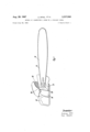
- FIG. 1 diagrammatically illustrates a chain saw equipped with a clutch-sprocket wheel connection effected according to the present invention.
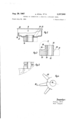
- FIG. 2 illustrates partly in section and partly in view a clutch drum connected to the driving sprocket wheel of a motor chain saw in conformity with the present invention.
- FIG. 3 illustrates in section and on a somewhat larger scale than FIG. 2 the sprocket wheel by itself; FIG. 3 representing a section taken along the line III-HI of FIG. 4.
- FIG. 4 is an axial top view of the hub of the sprocket wheel of FIG. 3.
- FIG. 5 illustrates in view that portion of FIG. 3 which is located within the dot-dash line circle V, but on a larger scale than that of FIG. 3.
- the present invention is characterized primarily in that the clutch drum is by upset riveting connected to a hub formed on the driving sprocket wheel.
- the clutch drum has an inwardly extending collar with a central bore as is known per se in connection with the abovementioned welded arrangements, it is advantageous in conformity with the present invention to provide an annular groove on the hub formed on said sprocket wheel, said groove being located near that end section of the m 3,33 7,940 Patented Aug. 29, 1967 hub which extends into the interior of the drum. It is into this annular groove that the collar of the drum is pressed by the upset riveting which reduces the axial length of said collar.
- the sprocket wheel is produced from a longitudinal section of a profiled bar containing the teeth of the wheel. This longitudinal section is at one end thereof, for purposes of forming the hub, turned or ma-' chined off to such an extent that the outer hub diameter will be slightly greater than the diameter of the dedendum line of the sprocket wheel.
- the motor chain saw shown therein is driven by a one cylinder twocycle internal combustion engine 10 of for instance 50 cubic centimeter stroke volume.
- This engine has a crankcase 11 to which is connected a guiding arm 12 for a saw chain 13.
- the motor chain saw is furthermore equipped with a fuel tank 14 behind which there is arranged a handle 15 connected to the crankcase 11 and serving for guiding the motor chain saw.
- the driving force of motor 10 is conveyed to saw chain 13 by an automatic centrifugal clutch which is coaxial to the motor crankshaft (not shown).
- the said centrifugal clutch has its outer clutch drum 18 rotatably connected to a driving sprocket wheel 19 for the saw chain 13. This connection may be effected in any convenient manner, for instance by upset riveting.
- Clutch drum 18 is deep drawn from a two millimeter strong steel sheet-metal and has anupwardly flanged reinforcing rim 20 as seen in FIG. 2.
- the clutch drum has two annular zones offset with regard to each other, namely an outer annular zone 21 and an inner annular zone 22.
- the clutch drum furthermore comprises a central collar 24 which extends into the interior of the drum and serves for connecting the drum to the driving sprocket wheel 19.
- the sprocket wheel 19 is produced from a longitudinal section of a profiled bar which has seven radially extending longitudinal ribs which will result in the teeth 25 of the sprocket wheel.
- the said ribs are turned or machined ofli' to such an extent that only very flat wedge portions or extensions 28 remain which protrude beyond the groove bottom 29 between the individual teeth 25.
- an annular groove 30 is cut into the circumference of hub 26.
- a 1 The method of mounting a drum on a sprocket wheel which comprises: turning a hub region on the end of a length of stock profiled to provide the teeth of the sprocket wheel so that at least the base portions of the teeth project from the hub, forming an axial flange about the central aperture of the drum to a diameter slightly less than the outside diameter ofthe tooth portions on the hub, pressing the drum on the hub with the axial flange engaging said tooth portions, and up setting the flange to fix the drum to the hub.
- a method according to claim 1 which includes forming an annular groove in the hub within the range of said flange whereby the upsetting of said flange will cause the flange to be displaced into said groove.
- a method according to claim 2 which includes forming the sprocket wheel teeth at the ends adjacent the hub so as to be co-planar and radial and forming an annular region on the drum surrounding the central aperture thereof, and pressing said annular region against said ends of the teeth while eifecting said upsetting to fixedly orient the axis of the drum relative to the axis of the sprocket wheel and hub.
- a method of connecting a drum having an end face wall with a central bore therethrough to a sprocket Wheel with teeth circumferentially spaced from each other which includes the steps of: forming a hub at one end of said sprocket wheel and providing said hub with annular groove means, providing said end face wall adjaceut said central bore thereof with an annular collar having an inner diameter approximately equalling the outer diameter of said hub, placing said collar on said hub, pressing said end face wall in axial direction of said hub between said teeth by a distance which is considerably less than the extension of said teeth in said axial direction so as to permit said teeth to function as sprocket wheel teeth, and upsetting said collar into gripping relation with said groove means.
Landscapes
- Life Sciences & Earth Sciences (AREA)
- Engineering & Computer Science (AREA)
- Mechanical Engineering (AREA)
- Wood Science & Technology (AREA)
- Forests & Forestry (AREA)
- Gears, Cams (AREA)
- Forging (AREA)
- Sawing (AREA)
- Machines For Laying And Maintaining Railways (AREA)
Applications Claiming Priority (5)
| Application Number | Priority Date | Filing Date | Title |
|---|---|---|---|
| DEST020920 | 1963-07-30 | ||
| DEST20921A DE1234371B (de) | 1963-07-30 | 1963-07-30 | Motorkettensaege |
| DE1963ST021432 DE1239837B (de) | 1963-12-07 | 1963-12-07 | Umlenkrad fuer Motorkettensaegen |
| DEST021709 | 1964-02-18 | ||
| FR983269A FR1404825A (fr) | 1963-07-30 | 1964-07-28 | Scie à chaîne à moteur |
Publications (1)
| Publication Number | Publication Date |
|---|---|
| US3337940A true US3337940A (en) | 1967-08-29 |
Family
ID=61569502
Family Applications (1)
| Application Number | Title | Priority Date | Filing Date |
|---|---|---|---|
| US385872A Expired - Lifetime US3337940A (en) | 1963-07-30 | 1964-07-29 | Method of connecting a drum to a sprocket wheel |
Country Status (10)
| Country | Link |
|---|---|
| US (1) | US3337940A (de) |
| AT (1) | AT245236B (de) |
| BE (2) | BE651057A (de) |
| CH (1) | CH411314A (de) |
| DE (1) | DE1234371B (de) |
| FI (1) | FI41198B (de) |
| FR (1) | FR1404825A (de) |
| GB (2) | GB1007810A (de) |
| LU (1) | LU46506A1 (de) |
| NL (1) | NL6407982A (de) |
Cited By (8)
| Publication number | Priority date | Publication date | Assignee | Title |
|---|---|---|---|---|
| US3868863A (en) * | 1972-11-07 | 1975-03-04 | Mcculloch Corp | Stamped sheet metal chain saw sprocket |
| US4406645A (en) * | 1980-10-30 | 1983-09-27 | Black & Decker Inc. | Sprocket-brake drum construction for chain saw |
| US4469376A (en) * | 1981-05-13 | 1984-09-04 | Keiper Automobiltechnik Gmbh & Co Kg | Hinge, particularly for seat with adjustable back rest and method of manufacturing the same |
| US4749131A (en) * | 1985-08-23 | 1988-06-07 | Robertshaw Controls Company | Burner construction and method of making the same |
| WO1991001859A1 (en) * | 1989-08-04 | 1991-02-21 | Beerens Cornelis J | Chain drive device and methods of forming same |
| US20040081509A1 (en) * | 2002-10-15 | 2004-04-29 | Hitachi Unisia Autimotive Ltd. | Structure and method of coupling shaft member and cylindrical member |
| US20060283684A1 (en) * | 2004-07-14 | 2006-12-21 | Thomas Beerens | Centrifugal drum clutch assembly and method of manufacture |
| US20120097781A1 (en) * | 2010-10-26 | 2012-04-26 | Trw Vehicle Safety Systems Inc. | Seat belt retractor with deep drawn spool |
Families Citing this family (2)
| Publication number | Priority date | Publication date | Assignee | Title |
|---|---|---|---|---|
| WO2009098699A1 (en) * | 2008-02-10 | 2009-08-13 | Toolgal Degania Industrial Diamonds Ltd. | Guide bar for power chain saws |
| DE102008054473A1 (de) * | 2008-12-10 | 2010-06-17 | Zf Friedrichshafen Ag | Anordnung zur Verbindung von zwei ein Drehmoment übertragenden Rotationsbauteilen |
Citations (3)
| Publication number | Priority date | Publication date | Assignee | Title |
|---|---|---|---|---|
| US2127969A (en) * | 1935-10-07 | 1938-08-23 | Gen Motors Corp | Method of assembling flat plates to shafts |
| US2429293A (en) * | 1943-06-30 | 1947-10-21 | Parsons Engineering Corp | Method of making rollers |
| US3105709A (en) * | 1961-05-02 | 1963-10-01 | Merlin S Hanke | Mechanical interlock union |
Family Cites Families (3)
| Publication number | Priority date | Publication date | Assignee | Title |
|---|---|---|---|---|
| DE1844855U (de) * | 1961-10-25 | 1962-01-11 | Motor G M B H Kommandit Ges As | Kettenritzel, insbesondere fuer die schneidketten von motorsaegen. |
| CH469162A (de) * | 1967-11-28 | 1969-02-28 | Belectra Ag Elektroartikel En | Vorrichtung zum Festhalten von Einbaukörpern an Schalungen für die Erstellung von Betonbauten oder Bauteilen davon |
| DE1810525A1 (de) * | 1968-11-23 | 1970-05-27 | Dieter Kupka | Vom Innendruck im Arbeitsraum gesteuerte Einrichtung zum Entlasten von mit Sperrfluessigkeit arbeitenden Gleitringdichtungen |
-
1963
- 1963-07-30 DE DEST20921A patent/DE1234371B/de active Pending
-
1964
- 1964-06-30 CH CH858264A patent/CH411314A/de unknown
- 1964-07-06 AT AT578664A patent/AT245236B/de active
- 1964-07-11 LU LU46506D patent/LU46506A1/xx unknown
- 1964-07-13 NL NL6407982A patent/NL6407982A/xx unknown
- 1964-07-15 FI FI1514/64A patent/FI41198B/fi active
- 1964-07-28 FR FR983269A patent/FR1404825A/fr not_active Expired
- 1964-07-28 BE BE651057D patent/BE651057A/fr unknown
- 1964-07-29 US US385872A patent/US3337940A/en not_active Expired - Lifetime
- 1964-07-30 BE BE651172D patent/BE651172A/fr unknown
- 1964-08-04 GB GB31122/64A patent/GB1007810A/en not_active Expired
- 1964-08-04 GB GB31121/64A patent/GB1028648A/en not_active Expired
Patent Citations (3)
| Publication number | Priority date | Publication date | Assignee | Title |
|---|---|---|---|---|
| US2127969A (en) * | 1935-10-07 | 1938-08-23 | Gen Motors Corp | Method of assembling flat plates to shafts |
| US2429293A (en) * | 1943-06-30 | 1947-10-21 | Parsons Engineering Corp | Method of making rollers |
| US3105709A (en) * | 1961-05-02 | 1963-10-01 | Merlin S Hanke | Mechanical interlock union |
Cited By (8)
| Publication number | Priority date | Publication date | Assignee | Title |
|---|---|---|---|---|
| US3868863A (en) * | 1972-11-07 | 1975-03-04 | Mcculloch Corp | Stamped sheet metal chain saw sprocket |
| US4406645A (en) * | 1980-10-30 | 1983-09-27 | Black & Decker Inc. | Sprocket-brake drum construction for chain saw |
| US4469376A (en) * | 1981-05-13 | 1984-09-04 | Keiper Automobiltechnik Gmbh & Co Kg | Hinge, particularly for seat with adjustable back rest and method of manufacturing the same |
| US4749131A (en) * | 1985-08-23 | 1988-06-07 | Robertshaw Controls Company | Burner construction and method of making the same |
| WO1991001859A1 (en) * | 1989-08-04 | 1991-02-21 | Beerens Cornelis J | Chain drive device and methods of forming same |
| US20040081509A1 (en) * | 2002-10-15 | 2004-04-29 | Hitachi Unisia Autimotive Ltd. | Structure and method of coupling shaft member and cylindrical member |
| US20060283684A1 (en) * | 2004-07-14 | 2006-12-21 | Thomas Beerens | Centrifugal drum clutch assembly and method of manufacture |
| US20120097781A1 (en) * | 2010-10-26 | 2012-04-26 | Trw Vehicle Safety Systems Inc. | Seat belt retractor with deep drawn spool |
Also Published As
| Publication number | Publication date |
|---|---|
| DE1234371B (de) | 1967-02-16 |
| NL6407982A (de) | 1965-02-01 |
| FR1404825A (fr) | 1965-07-02 |
| BE651172A (fr) | 1964-11-16 |
| FI41198B (de) | 1969-06-02 |
| GB1028648A (en) | 1966-05-04 |
| GB1007810A (en) | 1965-10-22 |
| AT245236B (de) | 1966-02-25 |
| BE651057A (fr) | 1964-11-16 |
| CH411314A (de) | 1966-04-15 |
| LU46506A1 (de) | 1964-09-11 |
Similar Documents
| Publication | Publication Date | Title |
|---|---|---|
| US3337940A (en) | Method of connecting a drum to a sprocket wheel | |
| US4131032A (en) | Rotary drive member | |
| US2729110A (en) | Sheet metal pulley construction for tooth grip belts | |
| US3678557A (en) | Method for making gear | |
| US3922932A (en) | Crenellation drum; and epicyclic transmission incorporating the same | |
| US4462269A (en) | Flywheel | |
| US2304721A (en) | Hydraulic transmission | |
| US5205464A (en) | Method for forming a lightweight flanged axle shaft | |
| US3519037A (en) | Saw chain driving apparatus | |
| US5012905A (en) | Double wrap brake band and its manufacturing method | |
| US4470290A (en) | Thin-wall sleeve forming | |
| JPS5868523A (ja) | 二重巻きブレーキバンド及びその製造方法 | |
| US3722309A (en) | Multiple groove sheave | |
| DE2741636A1 (de) | Riemenscheibe und verfahren zu ihrer herstellung | |
| US2787914A (en) | Double sheave pulley | |
| US3256967A (en) | Sheet metal clutch disc and hub | |
| US3868863A (en) | Stamped sheet metal chain saw sprocket | |
| US3610385A (en) | Motor chain saw | |
| GB2061449A (en) | Flywheel | |
| US4599775A (en) | Method for manufacturing synchronizer clutch teeth | |
| US5000612A (en) | Assembled driveshaft | |
| US3192862A (en) | Bladed element for fluid torque converters and the like | |
| US3786687A (en) | Unitized clutch drum and sprocket | |
| US5857546A (en) | Multiple-disk friction clutch | |
| US5626532A (en) | Drive assembly with interference-fit mounted lightweight non-ferrous pulley |