US20220120249A1 - Fuel Injection Device and Control Device - Google Patents
Fuel Injection Device and Control Device Download PDFInfo
- Publication number
- US20220120249A1 US20220120249A1 US17/418,955 US202017418955A US2022120249A1 US 20220120249 A1 US20220120249 A1 US 20220120249A1 US 202017418955 A US202017418955 A US 202017418955A US 2022120249 A1 US2022120249 A1 US 2022120249A1
- Authority
- US
- United States
- Prior art keywords
- injection hole
- fuel
- spray
- injection
- hole group
- Prior art date
- Legal status (The legal status is an assumption and is not a legal conclusion. Google has not performed a legal analysis and makes no representation as to the accuracy of the status listed.)
- Abandoned
Links
Images




Classifications
-
- F—MECHANICAL ENGINEERING; LIGHTING; HEATING; WEAPONS; BLASTING
- F02—COMBUSTION ENGINES; HOT-GAS OR COMBUSTION-PRODUCT ENGINE PLANTS
- F02M—SUPPLYING COMBUSTION ENGINES IN GENERAL WITH COMBUSTIBLE MIXTURES OR CONSTITUENTS THEREOF
- F02M61/00—Fuel-injectors not provided for in groups F02M39/00 - F02M57/00 or F02M67/00
- F02M61/16—Details not provided for in, or of interest apart from, the apparatus of groups F02M61/02 - F02M61/14
- F02M61/18—Injection nozzles, e.g. having valve seats; Details of valve member seated ends, not otherwise provided for
- F02M61/1806—Injection nozzles, e.g. having valve seats; Details of valve member seated ends, not otherwise provided for characterised by the arrangement of discharge orifices, e.g. orientation or size
- F02M61/1813—Discharge orifices having different orientations with respect to valve member direction of movement, e.g. orientations being such that fuel jets emerging from discharge orifices collide with each other
-
- F—MECHANICAL ENGINEERING; LIGHTING; HEATING; WEAPONS; BLASTING
- F02—COMBUSTION ENGINES; HOT-GAS OR COMBUSTION-PRODUCT ENGINE PLANTS
- F02M—SUPPLYING COMBUSTION ENGINES IN GENERAL WITH COMBUSTIBLE MIXTURES OR CONSTITUENTS THEREOF
- F02M61/00—Fuel-injectors not provided for in groups F02M39/00 - F02M57/00 or F02M67/00
- F02M61/16—Details not provided for in, or of interest apart from, the apparatus of groups F02M61/02 - F02M61/14
- F02M61/18—Injection nozzles, e.g. having valve seats; Details of valve member seated ends, not otherwise provided for
- F02M61/1806—Injection nozzles, e.g. having valve seats; Details of valve member seated ends, not otherwise provided for characterised by the arrangement of discharge orifices, e.g. orientation or size
-
- F—MECHANICAL ENGINEERING; LIGHTING; HEATING; WEAPONS; BLASTING
- F02—COMBUSTION ENGINES; HOT-GAS OR COMBUSTION-PRODUCT ENGINE PLANTS
- F02D—CONTROLLING COMBUSTION ENGINES
- F02D41/00—Electrical control of supply of combustible mixture or its constituents
- F02D41/30—Controlling fuel injection
- F02D41/38—Controlling fuel injection of the high pressure type
- F02D41/40—Controlling fuel injection of the high pressure type with means for controlling injection timing or duration
- F02D41/401—Controlling injection timing
-
- F—MECHANICAL ENGINEERING; LIGHTING; HEATING; WEAPONS; BLASTING
- F02—COMBUSTION ENGINES; HOT-GAS OR COMBUSTION-PRODUCT ENGINE PLANTS
- F02M—SUPPLYING COMBUSTION ENGINES IN GENERAL WITH COMBUSTIBLE MIXTURES OR CONSTITUENTS THEREOF
- F02M61/00—Fuel-injectors not provided for in groups F02M39/00 - F02M57/00 or F02M67/00
- F02M61/16—Details not provided for in, or of interest apart from, the apparatus of groups F02M61/02 - F02M61/14
- F02M61/18—Injection nozzles, e.g. having valve seats; Details of valve member seated ends, not otherwise provided for
- F02M61/1806—Injection nozzles, e.g. having valve seats; Details of valve member seated ends, not otherwise provided for characterised by the arrangement of discharge orifices, e.g. orientation or size
- F02M61/182—Discharge orifices being situated in different transversal planes with respect to valve member direction of movement
-
- F—MECHANICAL ENGINEERING; LIGHTING; HEATING; WEAPONS; BLASTING
- F02—COMBUSTION ENGINES; HOT-GAS OR COMBUSTION-PRODUCT ENGINE PLANTS
- F02M—SUPPLYING COMBUSTION ENGINES IN GENERAL WITH COMBUSTIBLE MIXTURES OR CONSTITUENTS THEREOF
- F02M61/00—Fuel-injectors not provided for in groups F02M39/00 - F02M57/00 or F02M67/00
- F02M61/16—Details not provided for in, or of interest apart from, the apparatus of groups F02M61/02 - F02M61/14
- F02M61/18—Injection nozzles, e.g. having valve seats; Details of valve member seated ends, not otherwise provided for
- F02M61/1806—Injection nozzles, e.g. having valve seats; Details of valve member seated ends, not otherwise provided for characterised by the arrangement of discharge orifices, e.g. orientation or size
- F02M61/1846—Dimensional characteristics of discharge orifices
-
- Y—GENERAL TAGGING OF NEW TECHNOLOGICAL DEVELOPMENTS; GENERAL TAGGING OF CROSS-SECTIONAL TECHNOLOGIES SPANNING OVER SEVERAL SECTIONS OF THE IPC; TECHNICAL SUBJECTS COVERED BY FORMER USPC CROSS-REFERENCE ART COLLECTIONS [XRACs] AND DIGESTS
- Y02—TECHNOLOGIES OR APPLICATIONS FOR MITIGATION OR ADAPTATION AGAINST CLIMATE CHANGE
- Y02T—CLIMATE CHANGE MITIGATION TECHNOLOGIES RELATED TO TRANSPORTATION
- Y02T10/00—Road transport of goods or passengers
- Y02T10/10—Internal combustion engine [ICE] based vehicles
- Y02T10/12—Improving ICE efficiencies
Definitions
- the present invention relates to, for example, a fuel injection device used in an internal combustion engine and a control device thereof.
- WO 2013/008692 A (PTL 1) describes a fuel injection valve having a large-diameter injection hole that injects fuel into an annular space including a region with a strong tumble flow and a small-diameter injection hole that injects fuel into a space including a region with a weak tumble flow (see ABSTRACT).
- This fuel injection valve reduces dilution of oil and reduces fuel adhesion or the like to a cylinder liner and a piston crown surface by reducing penetration of sprays directed to the cylinder liner and the piston crown surface and maintains an injection amount as a whole and appropriately controls combustion efficiency by directing the sprays of the increased penetration in a region with high fluidity (see paragraph 0015).
- a method for encouraging mixing of fuel and air to suppress unburned gas by increasing a system fuel pressure and atomizing particles of the injected fuel and a method for reducing unburned particles by suppressing the adhesion of the fuel sprays to an inside of an engine cylinder have been implemented.
- An object of the present invention is to enable forming of fuel sprays capable of suppressing discharge of PN, HC, and the like.
- a fuel injection device of the present invention is a fuel injection device having a plurality of injection holes, and the fuel injection device includes a first injection hole group that is directed in a direction on an exhaust valve side with respect to an intake valve side, and a second injection hole group that is directed in a direction on the intake valve side with respect to the exhaust valve side.
- a flow rate of the second injection hole group is larger than a flow rate of the first injection hole group.
- a fuel injection device of the present invention is a fuel injection device having a plurality of injection holes, and the fuel injection device includes a first injection hole group that is directed in a direction on an exhaust valve side with respect to an intake valve side, and a second injection hole group that is directed in a direction on the intake valve side with respect to the exhaust valve side.
- a total cross-sectional area of injection hole outlet surfaces of the second injection hole group is larger than a total cross-sectional area of injection hole outlet surfaces of the first injection hole group.
- a fuel injection device of the present invention is a fuel injection device having a plurality of injection holes, and a total cross-sectional area of injection holes that inject fuel in a direction along a flow direction of gas directed to an exhaust valve opening surface side from an intake valve opening surface side is smaller than a total cross-sectional area of injection holes that inject fuel in a direction facing the flow direction.
- FIG. 1 is a diagram showing a fuel injection system including a fuel injection device 100 and a drive device 150 according to an embodiment of the present invention, and is a diagram showing the fuel injection device 100 in a cross section parallel to a center axis 100 a.
- FIG. 2 is a schematic diagram of an in-cylinder direct injection type internal combustion engine (direct injection engine) in which fuel is directly injected into a cylinder inside and which is equipped with the fuel injection device 100 according to the embodiment of the present invention.
- direct injection engine direct injection type internal combustion engine
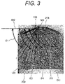
- FIG. 3 is a schematic diagram showing a form of fuel sprays injected into a cylinder inside (inside the cylinder 210 ) of FIG. 2 .
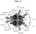
- FIG. 4 is a projection view of the fuel sprays injected from the fuel injection device 100 when FIG. 3 is viewed in a direction of a piston 214 from the fuel injection device 100 side.
- FIG. 5 is a projection view of the fuel sprays injected from the fuel injection device 100 when FIG. 3 is viewed in the direction of the fuel injection device 100 from the piston 214 side.
- FIG. 6 is an enlarged view of an orifice 116 viewed from a distal end direction of the fuel injection device 100 according to a first embodiment of the present invention.
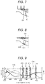
- FIG. 7 is a cross-sectional view of a cross section B-B′ in FIG. 6 .
- FIG. 8 is a diagram showing a change example in which a shape of an injection hole of the fuel injection device 100 according to the first embodiment of the present invention is changed.
- FIG. 9 is a diagram showing an injection method executed by a control device 154 according to the first embodiment of the present invention.
- FIG. 10 is a diagram showing a relationship between a flow rate ratio of a first injection hole group 801 and a second injection hole group 802 and PN according to the embodiment of the present invention.
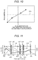
- FIG. 11 is a diagram showing an injection method executed by a control device 154 according to a second embodiment of the present invention.
- FIG. 12 is a projection view of fuel sprays injected from a fuel injection device 100 ′ when viewed in the direction of the fuel injection device 100 from a piston 209 side in FIG. 2 , in another example of the fuel injection device 100 (fuel injection device 100 ′).
- FIG. 13 is an enlarged view of an orifice 116 ′ viewed from a distal end direction of the fuel injection device 100 ′ of FIG. 12 .
- FIGS. 1 to 14 an operation and a configuration of a fuel injection device according to an embodiment of the present invention will be described with reference to FIGS. 1 to 14 .
- the same reference signs are assigned to configurations common in the drawings or embodiments, and the description thereof will be omitted for each drawing or embodiment. Even though the configurations have the same reference signs, whenever there is a particular need for description, the description will be given.
- FIG. 1 is a diagram showing a fuel injection system including a fuel injection device 100 and a drive device 150 according to an embodiment of the present invention, and is a diagram showing the fuel injection device 100 in a cross section parallel to a center axis 100 a.
- an up-down direction is based on an up-down direction of FIG. 1 , and does not necessarily match an up-down direction in a mounted state of the fuel injection device 100 .
- a side of the fuel injection device 100 on which injection holes 119 are provided is a distal end side, and an opposite side (a side on which fuel is supplied) is a base end side.
- Fuel injection of the fuel injection device 100 is controlled by a width of an injection pulse sent from an engine control unit (ECU) 154 .
- This injection pulse is input to a drive circuit 153 of the fuel injection device 100 , and the drive circuit 153 decides a drive current waveform based on an instruction from the ECU 154 and supplies a drive current to the fuel injection device 100 by a time based on the injection pulse.
- the drive circuit 153 may be mounted as a component or a board integrated with the ECU 154 .
- a device in which the drive circuit 154 and the ECU 154 are integrated is called the drive device 150 .
- the ECU 154 and the drive device 150 including the ECU 154 may be called a control device.
- the ECU 154 receives signals indicating states of an engine from various sensors, and calculates a width of an injection pulse and an injection timing for controlling an injection amount to be injected from the fuel injection device 100 according to an operating condition of an internal combustion engine.
- the ECU 154 includes an A/D converter and an I/O port for receiving signals from various sensors.
- the injection pulse output from the ECU 154 is input to the drive circuit 153 of the fuel injection device through a signal line 151 .
- the drive circuit 153 controls a voltage applied to a solenoid 105 and supplies a current to the solenoid 105 .
- the ECU 154 communicates with the drive circuit 153 through a communication line 152 , and can switch between drive currents generated by the drive circuit 153 according to a pressure of the fuel supplied to the fuel injection device 100 and the operating condition, and change set values of a current and a current supply time.
- the fuel injection device 100 in FIG. 1 is a normally closed valve type electromagnetic fuel injection device.
- a valve body 114 In a state in which the coil 105 is not energized, a valve body 114 is urged in a valve closing direction by a spring 110 , and comes in close contact with the valve seat 118 and is in a closed state.
- a mover (movable core) 102 In this closed state, a mover (movable core) 102 is brought into close contact with the valve body 114 by a zero spring 112 , and has a void between the mover 102 and a magnetic core (fixed core) 107 in a state in which the valve body 114 is closed.
- a magnetic circuit that generates an electromagnetic force for opening or closing a valve includes a nozzle holder 101 which is a cylindrical member disposed on an outer peripheral side of the magnetic core 107 and the mover 102 , the magnetic core 107 , the mover 102 , and a housing 103 .
- the valve body 114 is separated from the mover 102 and overshoots, but is pushed back by the spring 110 and stands still on the mover 102 .
- the supply of the current to the coil 105 is cut off, the magnetic flux generated in the magnetic circuit decreases, and the magnetic attraction force is reduced.
- the mover 102 and the valve body 114 move downward, and the mover 102 is separated from the valve body 114 at a point in time when the valve body 114 collides with the valve seat 118 .
- the valve body 114 stands still after colliding with the valve seat 118 , and the injection of the fuel is stopped.
- the mover 102 and the valve body 114 may be integrally molded as the same member, or may be formed as separate members and coupled by a method such as welding or press-fitting.
- a cylindrical orifice 116 having the plurality of injection holes 119 is coupled to the nozzle holder 101 , and the orifice 116 has a guide portion 120 that regulates movement of the valve body 114 in a radial direction.
- the orifice 116 and the guide portion 120 are integrally formed in FIG. 1 , but may be separate members.
- the movement of the valve body 214 is restricted in the radial direction at two points with inner diameters of the guide portion 120 and the magnetic core 107 that comes in sliding contact with a brim portion 130 of the valve body 114 , and the valve body is configured to operate in a valve opening direction and a valve closing direction (valve opening and closing directions).
- the zero spring 112 is not required.
- FIG. 2 is a schematic diagram of an in-cylinder direct injection type internal combustion engine (direct injection engine) in which the fuel is directly injected into a cylinder inside 208 and which is equipped with the fuel injection device 100 according to the embodiment of the present invention.
- FIG. 2 shows a state of fuel sprays on the engine cylinder inside 208 immediately after the fuel is injected from a distal end portion of the orifice 116 of the fuel injection device 100 .
- the engine cylinder inside 208 may be simply referred to as the in-cylinder.
- the direct injection engine in the present embodiment includes the fuel injection device 100 , intake valves 205 , an ignition plug 203 , exhaust valves 211 , an intake pipe 207 , an exhaust pipe 212 , a piston 209 , and a cylinder 220 including the piston 209 .
- the fuel injection device 100 is attached to a position 230 directly above the cylinder 220 , and two intake valve 205 and two exhaust valve 211 are attached to the left and right.
- FIG. 2 for the sake of description, the description will be made with reference to the drawing in which the intake valve 205 and the exhaust valve 211 are attached to the same cross section as the fuel injection device 100 .
- a left-right direction here is defined by a left-right direction on FIG. 2 .
- FIG. 3 is a schematic diagram showing a form of the fuel sprays injected into the cylinder inside (inside the cylinder 210 ) of FIG. 2 .
- FIG. 4 is a projection view of the fuel sprays injected from the fuel injection device 100 when FIG. 3 is viewed in a direction of the piston 214 from the fuel injection device 100 side.
- FIG. 5 is a projection view of the fuel sprays injected from the fuel injection device 100 when FIG. 3 is viewed in a direction of the fuel injection device 100 from the piston 214 side.
- an intake side (intake valve side or intake valve opening surface side) and an exhaust side (exhaust valve side or exhaust valve opening surface side) are partitioned as follows.
- the intake side and the exhaust side are partitioned by a surface 650 which is parallel to a center axis 220 a of the cylinder 220 or the cylinder 208 , includes the center axis 220 a , and is parallel to line segments passing through two intake valve opening surface centers 205 a or line segments passing through two exhaust valve opening surface centers 211 a .
- a side on which the intake valves 205 are present is the intake side and a side on which the exhaust valves 211 are present is the exhaust side.
- the intake side and the exhaust side may be partitioned symmetrically with respect to the surface 650 .
- the fuel sprays injected from the fuel injection device 100 include sprays 621 A and 621 B directed to the ignition plug 203 side on the exhaust side, sprays 621 C and 621 D directed to the piston 209 direction on the exhaust side, sprays 622 C and 622 D directed to the piston 209 direction on the intake side, and sprays 622 A and 622 B further directed to the intake valve 205 side than the sprays 622 C and 622 D on the intake side.
- the sprays 621 A and 621 B are further directed to the exhaust valve 211 side than the sprays 621 C and 621 D on the exhaust side.
- the fuel sprays injected from the fuel injection device 100 further have sprays 622 A and 623 B injected from the fuel injection device 100 in a direction substantially perpendicular to a crown surface 241 of the piston 209 .
- the sprays 621 A, 621 B, 621 C, and 621 D constitute a first spray group 621
- the sprays 622 A, 622 B, 622 C, and 622 D constitute a second spray group 622
- the sprays 623 A and 623 B constitute a third spray group 623 .
- FIG. 6 is an enlarged view of the orifice 116 viewed from a distal end direction of the fuel injection device 100 according to the first embodiment of the present invention.
- FIG. 7 is a sectional view of a cross section B-B′ in FIG. 6 .
- a seat surface 601 forming the valve seat 118 that seals the fuel has a substantially conical shape by coming in contact with the valve body 114 , and seals the fuel by coming in contact with a spherical portion 114 a (see FIG. 1 ) of the valve body 114 .
- the seat surface 601 has a seat portion 601 a coming in contact with the spherical portion 114 a .
- the injection holes 119 see FIG.
- the injection holes 801 A, 801 B, 801 C, 801 D, 802 A, 802 B, 802 C, 802 D, 803 A, and 803 B are formed in a cylindrical shape having a uniform injection hole diameter from an inlet side to an outlet side.
- FIG. 3 shows the state of the fuel sprays of the engine cylinder inside 208 immediately after the fuel is injected from the distal end portion of the orifice 116 of the fuel injection device 100 .
- the fuel sprays injected from the fuel injection device 100 have the first spray group 621 directed to the direction of the exhaust valve opening surface centers 211 a which are intersections between center axes 610 of the exhaust valves 211 and end surfaces (or exhaust valve opening surfaces) of the exhaust valves 211 on a combustion chamber side with respect to the intake valve opening surface centers 205 a which are intersections between center axes 611 of the intake valves 205 and the end surfaces (or intake valve opening surfaces) of the intake valves 205 on the combustion chamber side, and the second spray group 622 directed to the direction of the intake valve opening surface centers 205 a with respect to the exhaust valve opening surface centers 211 a .
- a flow rate of the second spray group 622 is higher than a flow rate of the first spray group 621 .
- Center axes of the sprays 621 A, 621 B, 621 C, and 621 D in the first spray group 621 are positioned on the exhaust valves 211 side of the combustion chamber center 650
- center axes of the spray 622 A, 622 B, 622 C, and 622 D in the second spray group 622 are positioned on the intake valves 205 side of the combustion chamber center 650 .
- the first spray group 621 is injected such that the center axes (injection directions) of the sprays 621 A, 621 B, 621 C, and 621 D are directed to the exhaust valves 211 side of the combustion chamber center 650
- the second spray group 622 is injected such that the center axes (injection directions) of the sprays 622 A, 622 B, 622 C, and 622 D are directed to the intake valves 205 side of the combustion chamber center 650 .
- the third spray group 623 is different from the first spray group 621 and the second spray group 622 in the present embodiment, the third spray group is included in the first spray group 621 when the center axes (injection directions) are directed to the exhaust side, and is included in the second spray group 622 when the center axes (injection directions) are directed to the intake side. Even in this case, a relationship between the flow rates of the first spray group 621 and the second spray group 622 satisfies the above-mentioned relationship.
- the flow of the air flowing into the engine cylinder inside from the intake port 207 forms a clockwise flow in the engine in-cylinder 208 , as indicated by a reference sign 240 in FIG. 2 .
- the following effects are obtained by disposing the fuel injection device 100 at the position 230 directly above the cylinder 220 and forming the fuel sprays as shown in FIG. 4 .
- a second injection hole group 802 injects the fuel in a direction against or in a region against the flow 240 , and thus, the injected fuel sprays are pushed back to the flow 240 .
- the fuel sprays injected from the second injection hole group 802 hardly adhere to a cylinder wall surface 210 and the crown surface 241 of the piston 209 .
- the first injection hole group 801 injects the fuel in a direction along the flow 240 , and thus, the injected fuel sprays follow the flow 240 . Accordingly, penetration increases, and thus, the fuel sprays easily adhere to the cylinder wall surface 210 and the crown surface 241 of the piston 209 .
- a flow rate of the second injection hole group 802 is higher than that of the first injection hole group 801 , and thus, it is possible to suppress the adhesion of the fuel to the cylinder wall surface 210 and the piston crown surface 241 . As a result, HC and PN can be reduced.
- a total cross-sectional area of injection hole outlet surfaces of the second injection hole group 802 is larger than a total cross-sectional area of injection hole outlet surfaces of the first injection hole group 801 .
- an inner diameter of an injection hole outlet of the second injection hole group 802 becomes larger than an inner diameter of an injection hole outlet of the first injection hole group 801 .
- the first injection hole group 801 includes the injection holes 801 A, 801 B, 801 C, and 801 D.
- the second injection hole group 802 includes the injection holes 802 A, 802 B, 802 C, and 802 D.
- the injection hole outlet surface corresponds to an injection hole outlet 901 in terms of the injection hole 801 .
- the injection hole has an annular shape having a uniform diameter from an inlet to an outlet in the present embodiment, a cross-sectional area of the injection hole outlet surface is important, and the shape of the injection hole may not have the annular shape or may be an ellipse or the like. The same applies to the other injection holes 802 and 803 .
- the inner diameter of the injection hole outlet of the second injection hole group 802 may be larger than the inner diameter of the injection hole outlet of the first injection hole group 801 .
- the total cross-sectional area of the injection holes of the second injection hole group 802 becomes larger than that of the first injection hole group 801 , and an effect of reducing PN is enhanced.
- the second injection hole group 802 is constituted by the four injection holes 802 A, 802 B, 802 C, and 802 D and the second spray group 622 is constituted by the four sprays 622 A, 622 B, 622 C, and 622 D in the present embodiment
- the number of sprays and the number of injection holes may be less than four. In this case, the number of injection holes is decreased, and thus, a processing time can be reduced. Accordingly, cost of the fuel injection device 100 can be suppressed.
- the fuel injection device 100 may be configured such that as intersection angles ⁇ 1 to ⁇ 5 between the injection holes (sprays) and a horizontal line 502 which is pulled to the intake valves 205 side in a horizontal direction of a combustion chamber (cylinder inside) 208 from a center 501 of a distal end portion of the fuel injection device 100 become larger, the flow rate of the sprays become smaller.
- the intersection angles become large in order from the intersection angles 503 to 507 .
- the diameters of the injection holes may be decreased in the order of the injection holes 802 A and 802 B, the injection holes 802 C and 802 D, the injection holes 803 A and 803 B, the injection holes 801 C and 801 D, and the injection holes 801 A and 801 B.
- the flow 240 goes around from the exhaust side to the intake side, and then flows in the vicinity of the intake valves 205 in parallel with the horizontal line 502 of the combustion chamber 208 . Accordingly, as the intersection angles between the horizontal line 502 and the sprays become smaller, the flow 240 and the sprays face each other. Thus, as the intersection angles between the horizontal line 502 and the sprays may become smaller, the flow rate may become larger. In other words, as the intersection angles between the horizontal line 502 and the injection holes may become larger, the flow rate of the sprays may become smaller. Even though the flow rate is increased, since the sprays are pushed back to the flow 240 , the sprays hardly adhere to the piston crown surface 241 and the cylinder wall surface 210 , and thus, PN can be suppressed.
- the flow 240 describes a tumble formed clockwise in the present embodiment.
- the flow 240 describes a tumble formed clockwise in the present embodiment.
- the flow rate of the sprays facing the flow is decreased by increasing the flow rate of the sprays facing the flow and decreasing the flow rate of the sprays along the flow.
- angles of the sprays will be described with reference to FIGS. 3 and 5 .
- an included angle formed by a spray pair constituted by the sprays 622 A and 622 B is ⁇ 1
- an included angle formed by a spray pair constituted by the sprays 622 C and 622 D is ⁇ 2
- an included angle formed by a spray pair constituted by the sprays 623 A and 623 B is ⁇ 3
- an included angle formed by a spray pair constituted by the sprays 621 C and 621 D is ⁇ 4
- an included angle formed by a spray pair constituted by the sprays 621 A and 621 B is ⁇ 5 .
- the included angle is an angle formed between spray center axes of the sprays forming the spray pair.
- the spray center axis is an axis that passes through a center of a spray cross section and is directed to an injection direction of the fuel injected from the injection hole. Since the injection direction of the fuel injected from the injection hole is set by a center axis (penetration direction) of the injection hole, the spray center axis may be considered to coincide with the center axis of the injection hole.
- the included angle ⁇ 1 between the center axes of the two sprays 622 A and 622 B formed by the two injection holes 802 A and 802 B that are part of the second injection hole group 802 may be smaller than the included angle ⁇ 5 between the spray center axes formed by the two sprays 621 A and 621 B injected from the two injection holes 801 A and 801 B which are part of the first injection hole group 801 .
- the included angles ⁇ 1 and ⁇ 2 are decreased such that the spray 622 of the second injection hole group 802 faces the flow 240 , and thus, a relative velocity between the sprays 622 A and 622 B and the flow 240 can be increased.
- the sprays are atomized, and thus, it is possible to suppress the adhesion of the fuel to the piston crown surface 214 and the cylinder wall surface 210 .
- the included angle ⁇ 1 is the smallest by being set to be smaller than the included angle ⁇ 2 . Since the spray 621 of the first injection hole group 801 is injected in the direction along the flow 240 , the included angles ⁇ 4 and ⁇ 5 are set to be larger than the included angles ⁇ 1 and ⁇ 2 .
- the included angle ⁇ 5 is set to be smaller than the included angle ⁇ 4 .
- the included angles ⁇ 4 and ⁇ 5 are set to be larger than the included angles ⁇ 1 and ⁇ 2 , and thus, an effect of extending the penetration with the flow 240 can be suppressed, and the fuel adhesion to the piston crown surface 214 or the cylinder wall surface 210 can be suppressed. According to the effects of the present embodiment, the fuel adhesion is suppressed, and thus, HC and PN can be reduced.
- the included angles between the spray center axes of the sprays other than the spray pair of 621 A and 621 B may become larger in order from the spray pairs closer to the exhaust side.
- intersection angle of the spray formed by the horizontal line 502 and the spray center axis of the spray 622 A or 622 B is ⁇ 1
- the intersection angle of the spray formed by the horizontal line 502 and the spray center axis of the spray 622 C or 622 D is 02
- the intersection angle of the spray formed by the horizontal line 502 and the spray center axis of the spray 623 A or 623 B is 03
- the intersection angle of the spray formed by the horizontal line 502 and the spray center axis of the spray 621 C or 621 D is 04
- the intersection angle of the spray formed by the horizontal line 502 and the spray 621 A or 621 B is 05.
- the included angles (angles) of the spray center axes of the sprays other than the spray pair of 621 A and 621 B may become larger.
- the included angles become large in order of ⁇ 1 , ⁇ 2 , ⁇ 3 , and ⁇ 4 . That is, ⁇ 1 , ⁇ 2 , ⁇ 3 , and ⁇ 4 have a relationship of ⁇ 1 ⁇ 2 ⁇ 3 ⁇ 4 .
- the included angles of the sprays become larger.
- the flow rate of the sprays along the flow 240 can be suppressed, and the effect of extending the penetration can be suppressed.
- the spray pair of 621 A and 621 B directed in the ignition plug 203 direction is injected, as the fuel, in the vicinity of the ignition plug 203 in order to improve ignitability.
- the fuel directly hits the ignition plug 203 , since fog may occur and combustion stability may deteriorate, it is necessary to secure the angle of a certain level or more. Accordingly, it is possible to achieve both combustion stability and adhesion reduction by setting the included angle ⁇ 5 to be smaller than the included angle ⁇ 4 and further setting the included angle ⁇ 5 to be larger than the included angle ⁇ 1 .
- FIG. 8 is a diagram showing a change example in which the shape of the injection hole of the fuel injection device 100 according to the first embodiment of the present invention is changed.
- the flow rate is decided by the inlet surface 1001 of which a cross-sectional area in a radial direction is minimized with respect to a center axis of the injection hole 1000 .
- the cross-sectional areas having the minimum cross-sectional areas may be compared, and the cross-sectional areas of the injection holes may be set.
- the fuel injection device 100 may be configured such that the sprays 622 C and 622 D included in the second spray group 622 are the sprays included in the first injection hole group 621 .
- the sprays 622 C and 622 D are included in the first injection hole group 621 .
- the flow rate of the injection holes 802 C and 802 D of the spray 622 C and 622 D is smaller than that of the injection holes 802 A and 802 B of the second spray group 622 .
- the angles between an orientation of the flow 240 and the sprays 622 C and 622 D are smaller than the angles between the orientation of the flow and the injection holes 802 A and 802 B of the second spray group 622 .
- the flow rate of the injection holes 802 C and 802 D is set to be smaller than that of the injection holes 802 A and 802 B, and thus, it is possible to suppress the adhesion of the fuel to the piston crown surface 241 and the cylinder 210 .
- the total cross-sectional area of the injection hole outlets of the injection holes 802 C and 802 D of the spray 622 C and 622 D may be smaller than that of the injection holes 802 A and 802 B of the second spray group 622 .
- the total cross-sectional area of the injection hole outlets of the injection holes 802 C and 802 D is decreased, since the penetration force of the sprays 622 C and 622 D is weaker than that of the sprays 622 A and 622 B injected from the injection holes 802 A and 802 B, even though the fuel is injected in a direction further deviating from the flow 240 than the injection holes 802 A and 802 B, the fuel adhesion to the cylinder 210 can be suppressed, and PN can be reduced.
- the included angle ⁇ 2 between the spray center axes of the sprays 622 C and 622 D may be larger than the included angle ⁇ 1 between the spray center axes of the second spray group 622 ( 622 A and 622 B).
- the included angle ⁇ 2 is set to be larger than the included angle ⁇ 1 of the sprays formed by the injection holes 802 A and 802 B of the second injection hole group 622 , and thus, a distance from the cylinder wall surface 210 or the piston crown surface 214 is secured, and the fuel adhesion can be suppressed. As a result, HC and PN can be reduced.
- the center axes of the sprays and the center axes of the injection holes have a substantially the same straight relationship.
- the center axes of the sprays 622 A and 622 B forming the second injection hole group 622 and the center axes of the injection holes 802 A and 802 B are substantially the same straight line.
- FIG. 9 is a diagram showing an injection method executed by the control device 154 according to the first embodiment of the present invention.
- FIG. 9 shows an injection timing and an injection period in the first embodiment.
- a crankshaft angle is represented on a horizontal axis.
- TDC of an intake stroke corresponds to ⁇ 360 deg
- BDC corresponds to ⁇ 180 deg
- TDC of a compression stroke corresponds to 0 deg.
- a lift amount of the intake valve 205 is indicated by a dotted line
- an average value of a turbulent velocity of the engine cylinder inside is indicated by a broken line
- a size of a tumble of the cylinder inside is indicated by a solid line.
- the fuel In order to suppress the fuel adhesion, it is effective to inject the fuel into compression stroke 1103 which has a high cylinder inside pressure.
- the fuel may be injected near BDC where a distance between the fuel injection device 100 and the piston crown surface 241 is long.
- the fuel is injected in the vicinity of the BDC, since the distance between the fuel injection device 100 and the piston crown surface 241 can be increased, the injected fuel hardly adheres to the piston crown surface 241 .
- the fuel may be injected at timing till, timing t 112 , and timing t 113 of compression stroke 703 .
- the total cross-sectional area of the injection hole outlet surfaces of the second injection hole group 802 is set to be larger than the total cross-sectional area of the injection hole outlet surfaces of the first injection hole group 801 , and thus, the flow rate of the sprays facing the flow 240 becomes large. Accordingly, a relative velocity between the air and the fuel becomes high, and thus, the fuel becomes atomized and easily diffuses into the cylinder inside. As a result, even though the fuel is injected in compression stroke 1103 , the fuel and the air are easily mixed, and the rich air-fuel mixture can be suppressed. In particular, although an example in which the fuel is injected three times in the compression stroke has been described in FIG. 9 , when more fuel is injected in the compression stroke than in the intake stroke, the effects of the present invention are enhanced.
- an effect of reducing PN is enhanced by achieving both the reduction of the fuel adhesion and the reduction of the rich equivalence ratio.
- the fuel is injected such that the second spray group 622 is directed to an intake valve inside 642 between the two intake valve opening surface centers 205 a with respect to an exhaust valve inside 641 between the two exhaust valve opening surface centers 211 a and the first spray group 621 is directed to an exhaust valve inside 641 with respect to the intake valve inside 642 .
- the fuel is injected such that the second injection hole group 802 is directed to the inside of the two intake valve opening surface centers 205 a with respect to the inside of the two exhaust valve opening surface centers 211 a and the first injection hole group 801 is directed to the inside of the two exhaust valve opening surface centers 211 a with respect to the inside of the two intake valve opening surface centers 205 a . Accordingly, an effect of suppressing the fuel from adhering to the piston crown surface 214 and the cylinder wall surface 210 is improved.
- FIG. 10 is a diagram showing a relationship between the flow rate ratio of the first injection hole group 801 and the second injection hole group 802 and PN according to the embodiment of the present invention.
- PN is the number of pieces of soot per unit volume
- 1201 is a target value of the PN.
- a configuration of the combustion injection device 100 is the same as that of the first embodiment.
- the fuel injection device 100 having the plurality of injection holes in the second embodiment includes the first injection hole group 801 directed in the direction of the exhaust valve opening surface centers 211 a with respect to the intake valve opening surface centers 205 a and the second injection hole group 802 directed in the direction of the intake valve opening surface centers 205 a with respect to the exhaust valve opening surface centers 211 a , and the total cross-sectional area of the injection hole outlet surfaces of the second injection hole group 802 is more than 1.3 times larger than the total cross-sectional area of the injection hole outlet surfaces of the first injection hole group 801 .
- the flow rate ratio between the first injection hole group 801 and the second injection hole group 802 which is obtained by dividing the flow rate of the first injection hole group 801 by the flow rate of the second injection hole group 802 becomes smaller, the PN discharged from the engine cylinder inside becomes smaller.
- the flow rate ratio between the first injection hole group 801 and the second injection hole group 802 may be set to 1.3 or less in order to achieve the PN target value for starting the cold air.
- FIG. 11 is a diagram showing an injection method executed by a control device 154 according to the second embodiment of the present invention.
- FIG. 11 shows an injection timing and an injection period in the third embodiment.
- a crankshaft angle is represented on a horizontal axis.
- TDC of an intake stroke corresponds to ⁇ 360 deg
- BDC corresponds to ⁇ 180 deg
- TDC of a compression stroke corresponds to 0 deg.
- a lift amount of the intake valve 205 is indicated by a dotted line
- an average value of a turbulent velocity of the engine cylinder inside is indicated by a broken line
- a size of a tumble of the cylinder inside is indicated by a solid line.
- the fuel injection device 100 may be controlled such that the fuel is injected at a timing from a time of the start of a lift of the intake valve 205 to a time of a maximum lift amount and a timing after a bottom dead center of BDC.
- the second spray group 621 of the second injection hole group 801 is pushed back to the flow 240 , and the fuel hardly adheres to the cylinder wall surface 210 and the piston crown surface 214 .
- the sprays hardly adhere to the piston crown surface 214 .
- the fuel may be injected at timing t 143 near BDC. That is, the fuel injection device 100 may be controlled such that the fuel is injected at the timing from a time of the start of the lift of the intake valve 205 to a time of the maximum lift amount and the timing after the bottom dead center. Since there is period 1401 from timing t 143 at which the fuel is injected to the end of the injection, when the injection period covers BDC, an effect of suppressing the fuel adhesion is obtained.
- Third injection 1404 may be performed at injection timing t 144 of compression stroke 1103 .
- the piston 209 moves upward and the cylinder inside pressure increases, even though the fuel is injected, the fuel hardly adheres to the cylinder wall surface 210 or the piston crown surface 214 .
- a flow rate in injection 1402 of intake stroke 1102 is set to be larger than a flow rate in injection 1404 of compression stroke 1103 , and thus, it is possible to achieve both the improvement of the homogeneity and the suppression of the adhesion.
- the flow rate in injection 1404 of which the injection timing is later than that in injection 1403 is set to be small, effects of improving the homogeneity and suppressing the adhesion are enhanced.
- FIG. 12 is a projection view of fuel sprays injected from a fuel injection device 100 ′ when viewed in the direction of the fuel injection device 100 from the piston 209 side in FIG. 2 , in another example of the fuel injection device 100 (fuel injection device 100 ′).
- FIG. 13 is an enlarged view of an orifice 116 ′ viewed from a distal end direction of the fuel injection device 100 ′ of FIG. 12 .
- the fuel sprays injected from the fuel injection device 100 ′ include sprays D 1 and D 2 directed to the exhaust side, that is, the ignition plug 203 side, D 3 and D 4 directed to the exhaust side, sprays D 5 and D 6 directed to the piston direction on the exhaust side, and sprays D 7 and D 8 directed to the intake side.
- a seat surface 601 ′ forming the valve seat 118 (see FIG. 1 ) that seals the fuel has a substantially conical shape by coming in contact with the valve body 114 (see FIG. 1 ), and seals the fuel by coming in contact with the spherical portion 114 a (see FIG. 1 ) of the valve body 114 .
- the injection holes include an injection hole 401 forming the spray D 1 , an injection hole 402 forming the spray D 2 , an injection hole 403 forming the spray D 3 , an injection hole 404 forming the spray D 4 , an injection hole 405 forming the spray D 5 , an injection hole 406 forming the spray D 6 , an injection hole 407 forming the spray D 7 , and an injection hole 408 forming the spray D 8 .
- the injection hole 407 and the injection hole 408 forming the sprays D 7 and D 8 arranged in the same straight line 301 are arranged in the vicinity substantially on the same circumference 422 , and the sprays are performed on the same straight line 301 from the position of the circumference 422 .
- the spray D 7 of the injection hole 407 has an angle of 430
- the spray D 8 of the injection hole 408 has an angle 431 .
- a distance 432 between the injection hole 407 and the injection hole 408 is set to be smaller than a distance 433 , a distance 434 , a distance 435 , a distance 436 , a distance 437 , a distance 438 , and a distance 439 between the other injection holes, and thus, the penetration force is strengthened by aligning directions of velocity vectors of the spray D 7 and the spray D 8 injected from the injection hole 407 and the injection hole 408 . Accordingly, a relative velocity between the spray D 7 and the spray D 8 and the flow 240 facing the spray D 8 is secured, and an effect of enhancing the atomization effect and an effect of improving the homogeneity can be obtained.
- the injection hole 407 of the spray D 7 is disposed on the exhaust side of the spray D 8 may be disposed inside on the circumference 422 than the injection hole 408 of the spray D 8 closest to the intake side. Due to this effect, since the injection hole 408 is positioned on an upstream side, the fuel easily flows, the penetration force of the spray D 8 facing the tumble is strengthened, and an atomization effect is enhanced.
- the fuel injection device includes a first injection hole group 801 that is directed in a direction on an exhaust valve 211 side with respect to an intake valve 205 side, and a second injection hole group 802 that is directed in a direction on the intake valve 205 side with respect to the exhaust valve 211 side.
- a flow rate of the second injection hole group 802 is larger than a flow rate of the first injection hole group 801 .
- the fuel injection device includes a first injection hole group 801 that is directed in a direction on an exhaust valve 211 side with respect to an intake valve 205 side, and a second injection hole group 802 that is directed in a direction on the intake valve 205 side with respect to the exhaust valve 211 side.
- a total cross-sectional area of injection hole outlet surfaces of the second injection hole group 802 is larger than a total cross-sectional area of injection hole outlet surfaces of the first injection hole group 801 .
- a total cross-sectional area of injection holes that inject fuel in a direction along a flow direction of gas directed to an opening surface side of an exhaust valve 211 from an opening surface side of an intake valve 205 is smaller than a total cross-sectional area of injection holes that inject fuel in a direction facing the flow direction.
- a total cross-sectional area of injection hole outlet surfaces of the second injection hole group 802 is larger than a total cross-sectional area of injection hole outlet surfaces of the first injection hole group 801 .
- the total cross-sectional area of the injection hole outlet surfaces of the second injection hole group 802 is more than 1.3 times larger than the total cross-sectional area of the injection hole outlet surfaces of the first injection hole group 801 .
- the second injection hole group 802 is directed to an inside 642 of two intake valve opening surface centers 205 a with respect to an inside 641 of two exhaust valve opening surface centers 211 a
- the first injection hole group 801 is directed to the inside 641 of the two exhaust valve opening surface centers 211 a with respect to the inside 642 of the two intake valve opening surface centers 205 a.
- an inner diameter of an injection hole outlet of the second injection hole group 802 is larger than an inner diameter of an injection hole outlet of the first injection hole group 801 .
- the first injection hole group 801 has a first injection hole pair of 801 A and 801 B that injects a first spray pair of 621 A and 621 B
- the second injection hole group 802 has a second injection hole pair of 802 A and 802 B that injects a second spray pair of 622 A and 622 B
- an included angle ⁇ 5 formed by spray center axes of the first spray pair of 801 A and 801 B is larger than an included angle ⁇ 1 formed by spray center axes of the second spray pair of 622 A and 622 B.
- the first injection hole group 801 has a third injection hole pair of 801 C and 801 D that injects a third spray pair of 621 C and 621 D further directed to the intake valve 205 side than the first spray pair of 621 A and 621 B on the exhaust valve 211 side
- the second injection hole group 802 has a fourth injection hole pair of 802 C and 802 D that injects a fourth spray pair of 622 C and 622 D further directed to the exhaust valve 211 side from the second spray pair of 802 A and 802 B on the intake valve 205 side
- an included angle ⁇ 4 formed by spray center axes of the third spray pair of 621 C and 621 D is large than an included angle ⁇ 1 formed by spray center axes of the second spray pair of 622 A and 622 B.
- the fuel injection device 100 is attached to a position 230 directly above a cylinder 220 .
- the fuel injection device 100 is controlled such that fuel is injected at a timing from a time of a start of a lift of an intake valve 205 to a time of a maximum lift amount and a timing after a bottom dead center.
- the present invention is not limited to the aforementioned embodiments, and includes various modification examples.
- the aforementioned embodiments are described in detail in order to facilitate easy understanding of the present invention, and are not limited to necessarily include all the components.
- Some of the components of a certain embodiment can be substituted into the components of another embodiment, and the components of another embodiment can be added to the component of a certain embodiment.
- the components of another embodiment can be added, removed, and substituted to, from, and into some of the components of the aforementioned embodiments.
Landscapes
- Engineering & Computer Science (AREA)
- Chemical & Material Sciences (AREA)
- Combustion & Propulsion (AREA)
- Mechanical Engineering (AREA)
- General Engineering & Computer Science (AREA)
- Fuel-Injection Apparatus (AREA)
Applications Claiming Priority (3)
| Application Number | Priority Date | Filing Date | Title |
|---|---|---|---|
| JP2019021460A JP7187341B2 (ja) | 2019-02-08 | 2019-02-08 | 燃料噴射装置および制御装置 |
| JP2019-021460 | 2019-02-08 | ||
| PCT/JP2020/004724 WO2020162587A1 (ja) | 2019-02-08 | 2020-02-07 | 燃料噴射装置および制御装置 |
Publications (1)
| Publication Number | Publication Date |
|---|---|
| US20220120249A1 true US20220120249A1 (en) | 2022-04-21 |
Family
ID=71948332
Family Applications (1)
| Application Number | Title | Priority Date | Filing Date |
|---|---|---|---|
| US17/418,955 Abandoned US20220120249A1 (en) | 2019-02-08 | 2020-02-07 | Fuel Injection Device and Control Device |
Country Status (4)
| Country | Link |
|---|---|
| US (1) | US20220120249A1 (ja) |
| JP (1) | JP7187341B2 (ja) |
| DE (1) | DE112020000270T5 (ja) |
| WO (1) | WO2020162587A1 (ja) |
Cited By (1)
| Publication number | Priority date | Publication date | Assignee | Title |
|---|---|---|---|---|
| CN118622503A (zh) * | 2024-06-28 | 2024-09-10 | 中国船舶集团有限公司第七一一研究所 | 一种发动机系统及发动机燃烧组织方法 |
Families Citing this family (1)
| Publication number | Priority date | Publication date | Assignee | Title |
|---|---|---|---|---|
| JP7529580B2 (ja) * | 2021-01-19 | 2024-08-06 | 本田技研工業株式会社 | 内燃機関 |
Citations (6)
| Publication number | Priority date | Publication date | Assignee | Title |
|---|---|---|---|---|
| US20080210195A1 (en) * | 2007-02-13 | 2008-09-04 | Hitachi, Ltd. | Apparatus for and method of controlling intake operation of an internal combustion engine |
| US20140130772A1 (en) * | 2011-07-11 | 2014-05-15 | Bosch Corporation | Fuel injection valve, internal combustion engine and fuel injection method |
| US20140251261A1 (en) * | 2011-11-10 | 2014-09-11 | Daimler Ag | Injection Nozzle |
| US20190040790A1 (en) * | 2016-02-24 | 2019-02-07 | Hitachi Automotive Systems, Ltd. | Fuel injection device |
| US20210172397A1 (en) * | 2019-12-06 | 2021-06-10 | Mazda Motor Corporation | Control device for compression self-ignition engine |
| US11136954B2 (en) * | 2017-12-08 | 2021-10-05 | Hitachi Automotive Systems, Ltd. | Fuel injection valve |
Family Cites Families (2)
| Publication number | Priority date | Publication date | Assignee | Title |
|---|---|---|---|---|
| JP4069750B2 (ja) * | 2003-01-31 | 2008-04-02 | 日産自動車株式会社 | 筒内直噴火花点火式内燃機関 |
| JP6945356B2 (ja) * | 2017-05-31 | 2021-10-06 | 日立Astemo株式会社 | 燃料噴射制御装置 |
-
2019
- 2019-02-08 JP JP2019021460A patent/JP7187341B2/ja active Active
-
2020
- 2020-02-07 US US17/418,955 patent/US20220120249A1/en not_active Abandoned
- 2020-02-07 WO PCT/JP2020/004724 patent/WO2020162587A1/ja not_active Ceased
- 2020-02-07 DE DE112020000270.5T patent/DE112020000270T5/de active Pending
Patent Citations (6)
| Publication number | Priority date | Publication date | Assignee | Title |
|---|---|---|---|---|
| US20080210195A1 (en) * | 2007-02-13 | 2008-09-04 | Hitachi, Ltd. | Apparatus for and method of controlling intake operation of an internal combustion engine |
| US20140130772A1 (en) * | 2011-07-11 | 2014-05-15 | Bosch Corporation | Fuel injection valve, internal combustion engine and fuel injection method |
| US20140251261A1 (en) * | 2011-11-10 | 2014-09-11 | Daimler Ag | Injection Nozzle |
| US20190040790A1 (en) * | 2016-02-24 | 2019-02-07 | Hitachi Automotive Systems, Ltd. | Fuel injection device |
| US11136954B2 (en) * | 2017-12-08 | 2021-10-05 | Hitachi Automotive Systems, Ltd. | Fuel injection valve |
| US20210172397A1 (en) * | 2019-12-06 | 2021-06-10 | Mazda Motor Corporation | Control device for compression self-ignition engine |
Cited By (1)
| Publication number | Priority date | Publication date | Assignee | Title |
|---|---|---|---|---|
| CN118622503A (zh) * | 2024-06-28 | 2024-09-10 | 中国船舶集团有限公司第七一一研究所 | 一种发动机系统及发动机燃烧组织方法 |
Also Published As
| Publication number | Publication date |
|---|---|
| JP7187341B2 (ja) | 2022-12-12 |
| JP2020128725A (ja) | 2020-08-27 |
| WO2020162587A1 (ja) | 2020-08-13 |
| DE112020000270T5 (de) | 2021-09-23 |
Similar Documents
| Publication | Publication Date | Title |
|---|---|---|
| JP6725723B2 (ja) | 燃料噴射装置 | |
| US7344090B2 (en) | Asymmetric fluidic flow controller orifice disc for fuel injector | |
| US6520144B2 (en) | Cylinder injection type internal combustion engine, control method for internal combustion engine, and fuel injection valve | |
| US6588399B2 (en) | Fuel injection method of internal combustion engine and fuel injection apparatus of internal combustion engine | |
| JP2008280981A (ja) | 燃料噴射装置およびそれを搭載した内燃機関 | |
| US10995655B2 (en) | Fuel injection device | |
| US20060157018A1 (en) | Fuel injection equipment, internal combustion engine, and control method of fuel injection equipment | |
| JP2004100500A (ja) | 燃料噴射弁およびそれを搭載した内燃機関 | |
| US20210190025A1 (en) | Fuel injection valve | |
| JP7187341B2 (ja) | 燃料噴射装置および制御装置 | |
| WO2018221076A1 (ja) | 燃料噴射弁及びエンジンシステム | |
| US10677209B2 (en) | Fuel injection device | |
| WO2017060945A1 (ja) | 燃料噴射弁 | |
| CN105386916A (zh) | 燃料喷射阀 | |
| JP3734924B2 (ja) | エンジンの燃料噴射弁 | |
| JP6655724B2 (ja) | 燃料噴射装置 | |
| US10677208B2 (en) | Fuel injection device | |
| JPH02125956A (ja) | 電磁式燃料噴射弁 | |
| JP2000097030A (ja) | 筒内噴射式内燃機関および筒内噴射用燃料噴射弁 | |
| JP3020899B2 (ja) | 電磁式燃料噴射弁 | |
| JP2000018136A (ja) | エンジンの燃料噴射弁及び燃料噴射方法 | |
| JP2017210933A (ja) | 燃料噴射装置 | |
| JPH051643A (ja) | 電磁式燃料噴射弁 | |
| JP2000314354A (ja) | 筒内燃料噴射装置 |
Legal Events
| Date | Code | Title | Description |
|---|---|---|---|
| AS | Assignment |
Owner name: HITACHI ASTEMO, LTD., JAPAN Free format text: ASSIGNMENT OF ASSIGNORS INTEREST;ASSIGNORS:KUSAKABE, RYO;SUKEGAWA, YOSHIHIRO;SARUWATARI, MASAYUKI;SIGNING DATES FROM 20210513 TO 20210611;REEL/FRAME:056914/0396 |
|
| STPP | Information on status: patent application and granting procedure in general |
Free format text: DOCKETED NEW CASE - READY FOR EXAMINATION |
|
| STPP | Information on status: patent application and granting procedure in general |
Free format text: NON FINAL ACTION MAILED |
|
| STPP | Information on status: patent application and granting procedure in general |
Free format text: RESPONSE TO NON-FINAL OFFICE ACTION ENTERED AND FORWARDED TO EXAMINER |
|
| STPP | Information on status: patent application and granting procedure in general |
Free format text: FINAL REJECTION MAILED |
|
| STCB | Information on status: application discontinuation |
Free format text: ABANDONED -- FAILURE TO RESPOND TO AN OFFICE ACTION |