US20220097760A1 - Vehicle steering device - Google Patents
Vehicle steering device Download PDFInfo
- Publication number
- US20220097760A1 US20220097760A1 US17/422,322 US201917422322A US2022097760A1 US 20220097760 A1 US20220097760 A1 US 20220097760A1 US 201917422322 A US201917422322 A US 201917422322A US 2022097760 A1 US2022097760 A1 US 2022097760A1
- Authority
- US
- United States
- Prior art keywords
- unit
- torque
- value
- steering
- angle
- Prior art date
- Legal status (The legal status is an assumption and is not a legal conclusion. Google has not performed a legal analysis and makes no representation as to the accuracy of the status listed.)
- Abandoned
Links
Images


Classifications
-
- B—PERFORMING OPERATIONS; TRANSPORTING
- B62—LAND VEHICLES FOR TRAVELLING OTHERWISE THAN ON RAILS
- B62D—MOTOR VEHICLES; TRAILERS
- B62D6/00—Arrangements for automatically controlling steering depending on driving conditions sensed and responded to, e.g. control circuits
- B62D6/008—Control of feed-back to the steering input member, e.g. simulating road feel in steer-by-wire applications
-
- B—PERFORMING OPERATIONS; TRANSPORTING
- B62—LAND VEHICLES FOR TRAVELLING OTHERWISE THAN ON RAILS
- B62D—MOTOR VEHICLES; TRAILERS
- B62D6/00—Arrangements for automatically controlling steering depending on driving conditions sensed and responded to, e.g. control circuits
- B62D6/002—Arrangements for automatically controlling steering depending on driving conditions sensed and responded to, e.g. control circuits computing target steering angles for front or rear wheels
- B62D6/003—Arrangements for automatically controlling steering depending on driving conditions sensed and responded to, e.g. control circuits computing target steering angles for front or rear wheels in order to control vehicle yaw movement, i.e. around a vertical axis
-
- B—PERFORMING OPERATIONS; TRANSPORTING
- B62—LAND VEHICLES FOR TRAVELLING OTHERWISE THAN ON RAILS
- B62D—MOTOR VEHICLES; TRAILERS
- B62D5/00—Power-assisted or power-driven steering
- B62D5/04—Power-assisted or power-driven steering electrical, e.g. using an electric servo-motor connected to, or forming part of, the steering gear
- B62D5/0457—Power-assisted or power-driven steering electrical, e.g. using an electric servo-motor connected to, or forming part of, the steering gear characterised by control features of the drive means as such
- B62D5/046—Controlling the motor
- B62D5/0463—Controlling the motor calculating assisting torque from the motor based on driver input
Definitions
- the present invention relates to a vehicle steering device.
- An electric power steering device as a vehicle steering device applies assist force (steering supplementary force) to a steering system of the vehicle through rotational force of a motor.
- the EPS applies, as the assist force, drive power of the motor, which is controlled by electrical power supplied from an inverter, to a steering shaft or a rack shaft through a transmission mechanism including a deceleration mechanism.
- Patent Literature 1 a vehicle steering device configured to increase stability of a vehicle by avoiding oversteer and understeer in traveling on a low- ⁇ road has been disclosed (for example, Patent Literature 1).
- the present invention is made in view of the above-described problem and is intended to provide a vehicle steering device capable of feeding loss of the grip force of a tire back to a driver.
- a vehicle steering device configured to assist and control a steering system of a vehicle by driving and controlling a motor configured to assist steering force, the vehicle steering device comprising a target steering torque generation unit configured to generate target steering torque of the motor, wherein the target steering torque generation unit generates target steering torque in accordance with the difference value of a torque signal in accordance with a steering angle and a vehicle speed from a value obtained by multiplying a physical quantity generated through tire slipping by a predetermined proportionality coefficient.
- the target steering torque generation unit generates the target steering torque by multiplying the torque signal by a torque adjustment coefficient value in accordance with the difference value.
- the target steering torque generation unit reduces the torque adjustment coefficient value as the difference value is larger.
- the amount of correction of the torque signal in accordance with the steering angle and the vehicle speed can be increased as deviation of the torque signal from vehicle behavior increases.
- the torque adjustment coefficient value be a positive value equal to or smaller than one.
- the target steering torque can be appropriately set.
- the target steering torque generation unit generates the target steering torque by subtracting, from the torque signal, a torque adjustment subtraction value in accordance with the difference value.
- the target steering torque generation unit increases the torque adjustment subtraction value as the difference value is larger.
- the amount of correction of the torque signal in accordance with the steering angle and the vehicle speed can be increased as deviation of the torque signal from vehicle behavior increases.
- the torque adjustment subtraction value is smaller than the torque signal.
- the target steering torque can be appropriately set.
- the physical quantity is self-aligning torque.
- the physical quantity is a yaw rate.
- the physical quantity is a current command value of the motor.
- FIG. 1 is a diagram illustrating a typical configuration of an electric power steering device.
- FIG. 2 is a schematic diagram illustrating a hardware configuration of a control unit configured to control the electric power steering device.
- FIG. 3 is a diagram illustrating an exemplary internal block configuration of the control unit in the electric power steering device.
- FIG. 4 is a structural diagram illustrating exemplary installation of a rudder angle sensor.
- FIG. 5 is a diagram illustrating an exemplary internal block configuration of a control unit according to a first embodiment.
- FIG. 6 is an explanatory diagram of a steering direction.
- FIG. 7 is a flowchart illustrating exemplary operation of the control unit according to the first embodiment.
- FIG. 8 is a block diagram illustrating an exemplary configuration of a target steering torque generation unit of the first embodiment.
- FIG. 9 is a diagram illustrating exemplary characteristics of a basic map held by a basic map unit.
- FIG. 10 is a diagram illustrating exemplary characteristics of a damper gain map held by a damper gain map unit.
- FIG. 11 is a diagram illustrating exemplary characteristics of a hysteresis correction unit.
- FIG. 12 is a block diagram illustrating an exemplary configuration of a low- ⁇ road torque correction value calculation unit of the first embodiment.
- FIG. 13 is a diagram illustrating change of real self-aligning torque on a low- ⁇ road.
- FIG. 14 is a diagram illustrating exemplary characteristics of a torque adjustment coefficient value map held by a torque adjustment coefficient value map unit of the first embodiment.
- FIG. 15 is a diagram illustrating an exemplary effect of a torque adjustment coefficient value output from the low- ⁇ road torque correction value calculation unit.
- FIG. 16 is a block diagram illustrating an exemplary configuration of a twist angle control unit of the first embodiment.
- FIG. 17 is a block diagram illustrating an exemplary configuration of a target steering torque generation unit of a first modification of the first embodiment.
- FIG. 18 is a block diagram illustrating an exemplary configuration of a low- ⁇ road torque correction value calculation unit of the first modification of the first embodiment.
- FIG. 19 is a diagram illustrating exemplary characteristics of a torque adjustment subtraction value map held by a torque adjustment subtraction value map unit of the first modification of the first embodiment.
- FIG. 20 is a diagram illustrating an exemplary internal block configuration of a control unit according to a second modification of the first embodiment.
- FIG. 21 is a block diagram illustrating an exemplary configuration of a target steering torque generation unit of the second modification of the first embodiment.
- FIG. 22 is a block diagram illustrating an exemplary configuration of a low- ⁇ road torque correction value calculation unit of the second modification of the first embodiment.
- FIG. 23 is a block diagram illustrating an exemplary configuration of a target steering torque generation unit of a third modification of the first embodiment.
- FIG. 24 is a block diagram illustrating an exemplary configuration of a low- ⁇ road torque correction value calculation unit of the third modification of the first embodiment.
- FIG. 25 is a diagram illustrating an exemplary internal block configuration of a control unit according to a second embodiment.
- FIG. 26 is a block diagram illustrating an exemplary configuration of a target steering torque generation unit of the second embodiment.
- FIG. 27 is a block diagram illustrating an exemplary configuration of an SAT information correction unit.
- FIG. 28 is a schematic diagram illustrating the status of torque generated between a road surface and steering.
- FIG. 29 is a diagram illustrating exemplary characteristics of a steering torque sensitive gain.
- FIG. 30 is a diagram illustrating exemplary characteristics of a vehicle speed sensitive gain.
- FIG. 31 is a diagram illustrating exemplary characteristics of a rudder angle sensitive gain.
- FIG. 32 is a diagram illustrating exemplary setting of the upper and lower limit values of a torque signal at a restriction unit.
- FIG. 33 is a block diagram illustrating an exemplary configuration of a twist angle control unit of the second embodiment.
- FIG. 34 is a block diagram illustrating an exemplary configuration of a target steering torque generation unit of a modification of the second embodiment.
- FIG. 35 is a diagram illustrating an exemplary configuration of an SBW system in a manner corresponding to the typical configuration of the electric power steering device illustrated in FIG. 1 .
- FIG. 36 is a block diagram illustrating the configuration of a third embodiment.
- FIG. 37 is a diagram illustrating an exemplary configuration of a target turning angle generation unit.
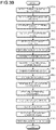
- FIG. 38 is a diagram illustrating an exemplary configuration of a turning angle control unit.
- FIG. 39 is a flowchart illustrating exemplary operation of the third embodiment.
- FIG. 40 is a block diagram illustrating an exemplary configuration of a low- ⁇ road torque correction value calculation unit of the third embodiment.
- FIG. 41 is a block diagram illustrating an exemplary configuration of a low- ⁇ road torque correction value calculation unit of a modification of the third embodiment.
- FIG. 1 is a diagram illustrating a typical configuration of an electric power steering device.
- the electric power steering device (EPS) as a vehicle steering device is coupled with steering wheels 8 L and 8 R through a column shaft (steering shaft or wheel shaft) 2 of a wheel 1 , a deceleration mechanism 3 , universal joints 4 a and 4 b , a pinion rack mechanism 5 , and tie rods 6 a and 6 b and further through hub units 7 a and 7 b in an order in which force provided by a steering person transfers.
- EPS electric power steering device
- a torque sensor 10 configured to detect steering torque Ts of the wheel 1 and a rudder angle sensor 14 configured to detect a steering angle ⁇ h are provided to the column shaft 2 including a torsion bar, and a motor 20 configured to assist steering force of the wheel 1 is coupled with the column shaft 2 through the deceleration mechanism 3 .
- Electrical power is supplied from a battery 13 to a control unit (ECU) 30 configured to control the electric power steering device, and an ignition key signal is input to the control unit 30 through an ignition key 11 .
- ECU control unit
- the control unit 30 performs calculation of a current command value of an assist (steering auxiliary) command based on the steering torque Ts detected by the torque sensor 10 and vehicle speed Vs detected by a vehicle speed sensor 12 , and controls current supplied to the motor 20 through a voltage control command value Vref obtained by providing compensation or the like to the current command value.
- the control unit 30 is connected with an on-board network such as a controller area network (CAN) 40 through which various kinds of information of a vehicle are transmitted and received.
- CAN controller area network
- the control unit 30 is connectable with a non-CAN 41 configured to transmit and receive communication other than the CAN 40 , analog and digital signals, radio wave, and the like.
- the control unit 30 is mainly configured as a CPU (including an MCU and an MPU).
- FIG. 2 is a schematic diagram illustrating a hardware configuration of the control unit configured to control the electric power steering device.
- a control computer 1100 configured as the control unit 30 includes a central processing unit (CPU) 1001 , a read only memory (ROM) 1002 , a random access memory (RAM) 1003 , an electrically erasable programmable rom (EEPROM) 1004 , an interface (I/F) 1005 , an analog/digital (A/D) converter 1006 , and a pulse width modulation (PWM) controller 1007 , and these components are connected with a bus.
- CPU central processing unit
- ROM read only memory
- RAM random access memory
- EEPROM electrically erasable programmable rom
- I/F interface
- A/D analog/digital
- PWM pulse width modulation
- the CPU 1001 is a processing device configured to execute a computer program for control (hereinafter referred to as a control program) of the electric power steering device and control the electric power steering device.
- a control program a computer program for control
- the ROM 1002 stores a control program for controlling the electric power steering device.
- the RAM 1003 is used as a work memory for operating the control program.
- the EEPROM 1004 stores, for example, control data input to and output from the control program. The control data is used on the control program loaded onto the RAM 1003 after the control unit 30 is powered on, and is overwritten to the EEPROM 1004 at a predetermined timing.
- the ROM 1002 , the RAM 1003 , the EEPROM 1004 , and the like are storage devices configured to store information and are storage devices (primary storage devices) directly accessible from the CPU 1001 .
- the A/D converter 1006 receives, for example, signals of the steering torque Ts, a detected current value Im of the motor 20 , and the steering angle ⁇ h and converts the signals into digital signals.
- the interface 1005 is connected with the CAN 40 .
- the interface 1005 receives a signal (vehicle speed pulse) of a vehicle speed V from the vehicle speed sensor 12 .
- the PWM controller 1007 outputs a PWM control signal of each UVW phase based on a current command value to the motor 20 .
- FIG. 3 is a diagram illustrating an exemplary internal block configuration of a control unit in an electric power steering device.
- the steering torque Ts and the vehicle speed Vs are input to a current command value calculation unit 31 .
- the current command value calculation unit 31 refers to, based on the steering torque Ts and the vehicle speed Vs, a look-up table (such as an assist map) stored in advance and calculates a current command value Iref 1 that is a control target value of current supplied to the motor 20 .
- a compensation signal generation unit 34 generates a compensation signal CM.
- the compensation signal generation unit 34 includes a convergence estimation unit 341 , an inertia estimation unit 342 , and a self-aligning torque (SAT) estimation unit 343 .
- the convergence estimation unit 341 estimates the yaw rate of the vehicle based on the angular velocity of the motor 20 , and estimates a compensation value with which shake operation of the wheel 1 is reduced to improve convergence of the yaw of the vehicle.
- the inertia estimation unit 342 estimates the inertial force of the motor 20 based on the angular acceleration of the motor 20 , and estimates a compensation value with which the inertial force of the motor 20 is compensated to increase response.
- the SAT estimation unit 343 estimates self-aligning torque T SAT based on the steering torque Ts, assist torque, and the angular velocity and angular acceleration of the motor 20 , and estimates a compensation value with which the assist torque is compensated with the self-aligning torque as reaction force.
- the compensation signal generation unit 34 may include an estimation unit configured to estimate another compensation value in addition to the convergence estimation unit 341 , the inertia estimation unit 342 , and the SAT estimation unit 343 .
- the compensation signal CM is a sum obtained by adding, at an addition unit 345 , the compensation value of the convergence estimation unit 341 and a sum obtained by adding the compensation value of the inertia estimation unit 342 and the compensation value of the SAT estimation unit 343 at an addition unit 344 .
- the self-aligning torque T SAT estimated by the SAT estimation unit 343 is also output to a target steering torque generation unit 200 to be described later.
- the compensation signal CM from the compensation signal generation unit 34 is added to the current command value Iref 1 , and characteristic compensation of a steering system is provided to the current command value Iref 1 through the addition of the compensation signal CM to improve convergence, an inertia characteristic, and the like. Then, the current command value Iref 1 becomes a current command value Iref 2 provided with characteristic compensation through the addition unit 32 A, and the current command value Iref 2 is input to a current restriction unit 33 . At the current restriction unit 33 , largest current of the current command value Iref 2 is restricted, and a current command value Irefm is generated.
- the current command value Irefm is input to a subtraction unit 32 B, and a deviation I (Irefm ⁇ Im) from the detected current value Im fed back from the motor 20 side is calculated at the subtraction unit 32 B.
- the deviation I is input to a PI control unit 35 for characteristic improvement of steering operation.
- the voltage control command value Vref characteristics of which are improved at the PI control unit 35 is input to a PWM control unit 36 , and in addition, the motor 20 is PWM-driven through an inverter circuit 37 as a motor drive unit.
- the detected current value Im of the motor 20 is detected by a current detector 38 and fed back to the subtraction unit 32 B.
- the inverter circuit 37 includes a field effect transistor (hereinafter referred to as a FET) as a drive element and is configured as a bridge circuit of the FET.
- a FET field effect transistor
- assist control by the conventional electric power steering device steering torque manually applied by a driver is detected by a torque sensor as twist torque of the torsion bar, and motor current is controlled as assist current mainly in accordance with the torque.
- the steering torque changes depending on the steering angle because of difference in the state (for example, tilt) of a road surface in some cases.
- the steering torque is also affected by variation of a motor output characteristic due to long-term use in some cases.
- FIG. 4 is a structural diagram illustrating exemplary installation of the rudder angle sensor.
- the column shaft 2 includes a torsion bar 2 A.
- Road surface reaction force Rr and road surface information act on the steering wheels 8 L and 8 R.
- An upper angle sensor is provided on the wheel side of the column shaft 2 with respect to the torsion bar 2 A.
- a lower angle sensor is provided on the steering wheel side of the column shaft 2 with respect to the torsion bar 2 A.
- the upper angle sensor detects a wheel angle ⁇ 1
- the lower angle sensor detects a column angle ⁇ 2 .
- the steering angle ⁇ h is detected by a rudder angle sensor provided at an upper part of the column shaft 2 .
- twist angle ⁇ of the torsion bar is expressed in Expression (1) below based on the deviation between the wheel angle ⁇ 1 and the column angle ⁇ 2 .
- torsion bar torque Tt is expressed in Expression (2) below by using the twist angle ⁇ of the torsion bar expressed in Expression (1).
- Kt represents the spring constant of the torsion bar 2 A.
- the torsion bar torque Tt may be detected by using a torque sensor.
- the torsion bar torque Tt is treated as the steering torque Ts.
- FIG. 5 is a diagram illustrating an exemplary internal block configuration of the control unit according to a first embodiment.
- the control unit 30 includes, as internal block components, a target steering torque generation unit 200 , a twist angle control unit 300 , a steering direction determination unit 400 , and a conversion unit 500 .
- wheel steering by the driver is assisted and controlled by the motor 20 of an EPS steering system/vehicle system 100 .
- the EPS steering system/vehicle system 100 includes an angle sensor and an angular velocity calculation unit in addition to the motor 20 .
- the target steering torque generation unit 200 generates a target steering torque Tref that is a target value of the steering torque when the steering system of the vehicle is assisted and controlled in the present disclosure.
- the conversion unit 500 converts the target steering torque Tref into a target twist angle ⁇ ref.
- the twist angle control unit 300 generates a motor current command value Iref that is a control target value of current supplied to the motor 20 .
- the twist angle control unit 300 calculates the motor current command value Iref with which the twist angle ⁇ is equal to the target twist angle ⁇ ref.
- the motor 20 is driven by the motor current command value Iref.
- the steering direction determination unit 400 determines whether the steering direction is right or left based on a motor angular velocity ⁇ m output from the EPS steering system/vehicle system 100 , and outputs a result of the determination as a steering state signal STs.
- FIG. 6 is an explanatory diagram of the steering direction.
- a steering state indicating whether the steering direction is right or left can be obtained as, for example, the relation between the steering angle ⁇ h and the motor angular velocity ⁇ m as illustrated in FIG. 6 .
- the steering direction is determined to be “right” when the motor angular velocity ⁇ m is a positive value, or the steering direction is determined to be “left” when the motor angular velocity ⁇ m is a negative value.
- an angular velocity calculated by performing speed calculation on the steering angle ⁇ h, the wheel angle ⁇ 1 , or the column angle ⁇ 2 may be used in place of the motor angular velocity ⁇ m.
- the conversion unit 500 converts the target steering torque Tref generated at the target steering torque generation unit 200 into the target twist angle ⁇ ref by using the relation of Expression (2) above.
- FIG. 7 is a flowchart illustrating exemplary operation of the control unit according to the first embodiment.
- the steering direction determination unit 400 determines whether the steering direction is right or left based on the sign of the motor angular velocity ⁇ m output from the EPS steering system/vehicle system 100 , and outputs a result of the determination as the steering state signal STs to the target steering torque generation unit 200 (step S 10 ).
- the target steering torque generation unit 200 generates the target steering torque Tref based on the vehicle speed Vs, a vehicle speed determination signal Vfail, the steering state signal STs, the steering angle ⁇ h, and a real yaw rate ⁇ re (step S 20 ).
- the conversion unit 500 converts the target steering torque Tref generated at the target steering torque generation unit 200 into the target twist angle ⁇ ref (step S 20 ).
- the target twist angle ⁇ ref is output to the twist angle control unit 300 .
- the twist angle control unit 300 calculates the motor current command value Iref based on the target twist angle ⁇ ref, the steering angle ⁇ h, the twist angle ⁇ , and the motor angular velocity ⁇ m (step S 30 ).
- step S 40 current control is performed to drive the motor 20 based on the motor current command value Iref output from the twist angle control unit 300 (step S 40 ).
- FIG. 8 is a block diagram illustrating an exemplary configuration of the target steering torque generation unit of the first embodiment.
- the target steering torque generation unit 200 includes a basic map unit 210 , a multiplication unit 211 , a sign extraction unit 213 , a differential unit 220 , a damper gain map unit 230 , a hysteresis correction unit 240 , a SAT information correction unit 250 , a multiplication unit 260 , addition units 261 , 262 , and 263 , and a low- ⁇ road torque correction value calculation unit 280 .
- FIG. 9 is a diagram illustrating exemplary characteristics of a basic map held by the basic map unit.
- FIG. 10 is a diagram illustrating exemplary characteristics of a damper gain map held by the damper gain map unit.
- the steering angle ⁇ h and the vehicle speed Vs are input to the basic map unit 210 .
- the basic map unit 210 outputs a torque signal Tref_a 0 having the vehicle speed Vs as a parameter by using the basic map illustrated in FIG. 9 . Specifically, the basic map unit 210 outputs the torque signal Tref_a 0 in accordance with the vehicle speed Vs.
- the torque signal Tref_a 0 has such a characteristic that the torque signal Tref_a 0 increases as the magnitude (absolute value)
- a torque signal Tref_a has such a characteristic that the torque signal Tref_a increases as the vehicle speed Vs increases.
- the map is configured in accordance with the magnitude
- the value of the torque signal Tref_a 0 can be positive and negative values.
- the configuration of the low- ⁇ road torque correction value calculation unit configured to calculate a correction value for the torque signal Tref_a 0 needs to be changed as appropriate.
- the following description will be made on an aspect of outputting the torque signal Tref_a 0 that is a positive value in accordance with the magnitude
- the sign extraction unit 213 extracts the sign of the steering angle ⁇ h. Specifically, for example, the value of the steering angle ⁇ h is divided by the absolute value of the steering angle ⁇ h. Accordingly, the sign extraction unit 213 outputs “1” when the sign of the steering angle ⁇ h is “+”, or outputs “ ⁇ 1” when the sign of the steering angle ⁇ h is “ ⁇ ”
- the steering angle ⁇ h is input to the differential unit 220 .
- the differential unit 220 calculates a rudder angular velocity ⁇ h that is angular velocity information by differentiating the steering angle ⁇ h.
- the differential unit 220 outputs the calculated rudder angular velocity ⁇ h to the multiplication unit 260 .
- the vehicle speed Vs is input to the damper gain map unit 230 .
- the damper gain map unit 230 outputs a damper gain D G in accordance with the vehicle speed Vs by using a vehicle speed sensitive damper gain map illustrated in FIG. 10 .
- the damper gain D G has such a characteristic that the damper gain D G gradually increases as the vehicle speed Vs increases.
- the damper gain D G may be variable in accordance with the steering angle ⁇ h.
- the multiplication unit 260 multiplies the rudder angular velocity ⁇ h output from the differential unit 220 by the damper gain D G output from the damper gain map unit 230 , and outputs a result of the multiplication as a torque signal Tref_b to the addition unit 262 .
- the steering direction determination unit 400 performs determination as illustrated in, for example, FIG. 6 .
- the steering angle ⁇ h, the vehicle speed Vs, and the steering state signal STs which is a result of the determination illustrated in FIG. 6 , are input to the hysteresis correction unit 240 .
- a coefficient “a” is a value larger than one
- a coefficient “c” is a value larger than zero.
- a coefficient Ahys indicates the output width of a hysteresis characteristic
- the coefficient “c” indicates the roundness of the hysteresis characteristic.
- the torque signal Tref_c (y R ) is calculated by using Expression (3) above.
- the torque signal Tref_c (y L ) is calculated by using Expression (4) above. Note that, when switching is made from right steering to left steering or when switching is made from left steering to right steering, a coefficient “b” or “b′” indicated in Expression (5) or (6) below is substituted into Expressions (3) and (4) above after steering switching based on the values of final coordinates (x 1 , y 1 ) that are the previous values of the steering angle ⁇ h and the torque signal Tref_c. Accordingly, continuity through steering switching is maintained.
- Expressions (5) and (6) above can be derived by substituting x 1 into x and substituting y 1 into y R and y L in Expressions (3) and (4) above.
- Expressions (3), (4), (5), and (6) above can be expressed as Expressions (7), (8), (9), and (10) below, respectively.
- FIG. 11 is a diagram illustrating exemplary characteristics of the hysteresis correction unit.
- the torque signal Tref_c output from the hysteresis correction unit 240 has a hysteresis characteristic such as the origin at zero ⁇ L 1 (thin line) ⁇ L 2 (dashed line) ⁇ L 3 (bold line).
- the coefficient Ahys which indicates the output width of the hysteresis characteristic
- the coefficient “c” which indicates the roundness thereof may be variable in accordance with one or both of the vehicle speed Vs and the steering angle ⁇ h.
- the rudder angular velocity ⁇ h is obtained through the differential calculation on the steering angle ⁇ h but is provided with low-pass filter (LPF) processing as appropriate to reduce influence of noise in a higher range.
- the differential calculation and the LPF processing may be performed with a high-pass filter (HPF) and a gain.
- the rudder angular velocity ⁇ h may be calculated by performing the differential calculation and the LPF processing not on the steering angle ⁇ h but on a wheel angle ⁇ 1 detected by the upper angle sensor or a column angle ⁇ 2 detected by the lower angle sensor.
- the motor angular velocity ⁇ m may be used as the angular velocity information in place of the rudder angular velocity ⁇ h, and in this case, the differential unit 220 is not needed.
- FIG. 12 is a block diagram illustrating an exemplary configuration of the low- ⁇ road torque correction value calculation unit of the first embodiment.
- the torque signal Tref_a 0 output from the basic map unit 210 (refer to FIG. 8 ) and the self-aligning torque T SAT output from the SAT estimation unit 343 (refer to FIG. 3 ) are input to the low- ⁇ road torque correction value calculation unit 280 .
- FIG. 13 is a diagram illustrating change of real self-aligning torque on a low- ⁇ road.
- the real self-aligning torque (also referred to as a SAT value) of a tire increases in accordance with increase of the magnitude (absolute value)
- the SAT value is substantially proportional to the torque signal Tref_a 0 output from the basic map unit 210 in a normal traveling state.
- a proportionality coefficient of the SAT value for the torque signal Tref_a 0 is “k”.
- the “normal traveling state” indicates a state in which the tire grips a road surface.
- FIG. 13 illustrates an example in which the SAT value decreases in a region equal to or larger than a steering angle ⁇ b when the road surface friction resistance ⁇ is 1.0, and the SAT value decreases in a region equal to or larger than a steering angle Ga when the road surface friction resistance ⁇ is 0.1.
- the torque signal Tref_a 0 output from the basic map unit 210 and a value obtained by multiplying the SAT value by the proportionality coefficient k deviate from each other.
- the driver does not notice loss of the grip force of the tire and an emergency avoidance operation potentially delays.
- loss of the grip force of the tire is fed back to the driver based on a physical quantity generated through tire slipping so that the driver can perform an emergency avoidance operation.
- the following describes a configuration that enables feedback of loss of the grip force of the tire to the driver by using, as the physical quantity generated through tire slipping, the self-aligning torque T SAT estimated by the SAT estimation unit 343 (refer to FIG. 3 ).
- the low- ⁇ road torque correction value calculation unit 280 of the first embodiment includes a proportionality coefficient multiplication unit 281 , a subtraction unit 282 , a torque adjustment coefficient value map unit 283 , and an absolute value calculation unit 284 .
- the self-aligning torque T SAT is input to the absolute value calculation unit 284 .
- the absolute value calculation unit 284 calculates the absolute value
- the proportionality coefficient multiplication unit 281 outputs, to the subtraction unit 282 , a value k(
- the value of the proportionality coefficient k is set to be a value with which the torque signal Tref_a 0 and the output value k(
- the subtraction unit 282 outputs, to the torque adjustment coefficient value map unit 283 , a value Tref_a 0 ⁇ k(
- the torque adjustment coefficient value map unit 283 holds a torque adjustment coefficient value map representing the relation between the output value Tref_a 0 ⁇ k(
- FIG. 14 is a diagram illustrating exemplary characteristics of the torque adjustment coefficient value map held by the torque adjustment coefficient value map unit of the first embodiment.
- the torque adjustment coefficient value G can have a positive value equal to or smaller than one.
- the torque adjustment coefficient value map indicates an example in which the torque adjustment coefficient value G is “1.0” in a region where the output value Tref_a 0 ⁇ k(
- the torque adjustment coefficient value map has such a characteristic that the torque adjustment coefficient value G gradually decreases from “1.0” to “0.1” in a region where the output value Tref_a 0 ⁇ k(
- ) of the subtraction unit 282 are set as appropriate.
- ) of the subtraction unit 282 is exemplary and not limited to “0.1” described above. These values are desirably values with which discomfort is not provided to the steering feeling of the driver.
- the torque adjustment coefficient value map may have curved characteristics in place of linear characteristics as illustrated in FIG. 14 .
- the torque adjustment coefficient value map unit 283 derives the torque adjustment coefficient value G in accordance with the output value Tref_a 0 ⁇ k(
- the torque adjustment coefficient value G may be calculated by using an expression representing the relation between the output value Tref_a 0 ⁇ k(
- the multiplication unit 211 multiplies the torque signal Tref_a 0 output from the basic map unit 210 by the sign of the steering angle ⁇ h output from the sign extraction unit 213 and the torque adjustment coefficient value G output from the low- ⁇ road torque correction value calculation unit 280 , and outputs the multiplied torque signal Tref_a 0 to the addition unit 261 as the torque signal Tref_a. Accordingly, the torque signal Tref_a in accordance with the positive and negative values of the steering angle ⁇ h is obtained.
- FIG. 15 is a diagram illustrating an exemplary effect of the torque adjustment coefficient value output from the low- ⁇ road torque correction value calculation unit.
- FIG. 15 illustrates an example in which the traveling state is normal, in other words, the tire grips a road surface until time t, and the grip force of the tire is gradually lost after the time t.
- ) of the proportionality coefficient multiplication unit 281 are substantially equal to each other until the time t (the solid line in the drawing).
- ) of the subtraction unit 282 is equal to or smaller than A, and the torque adjustment coefficient value G in this case is “1.0” (refer to FIG. 14 ).
- ) of the proportionality coefficient multiplication unit 281 , which is illustrated with a dashed and single-dotted line in the drawing gradually increases.
- ) of the subtraction unit 282 gradually increases from A.
- the torque adjustment coefficient value G in this case gradually decreases from “1.0” (refer to FIG. 14 ).
- the torque signal Tref_a becomes smaller than that in the normal traveling state (the solid line in the drawing) as illustrated with a dashed line in the drawing. Accordingly, the steering feeling becomes lighter than in the normal traveling state, and the driver can recognize loss of the grip force of the tire and perform an appropriate emergency avoidance operation.
- the twist angle control unit 300 of the first embodiment (refer to FIG. 5 ) will be described below with reference to FIG. 16 .
- FIG. 16 is a block diagram illustrating an exemplary configuration of the twist angle control unit of the first embodiment.
- the twist angle control unit 300 calculates the motor current command value Iref based on the target twist angle ⁇ ref, the twist angle ⁇ , the steering angle ⁇ h, and the motor angular velocity ⁇ m.
- the twist angle control unit 300 includes a twist angle feedback (FB) compensation unit 310 , a speed control unit 330 , a stabilization compensation unit 340 , an output restriction unit 350 , a rudder angle disturbance compensation unit 360 , a subtraction unit 361 , an addition unit 363 , and a speed reduction ratio unit 370 .
- FB twist angle feedback
- the target twist angle ⁇ ref output from the conversion unit 500 is input to the subtraction unit 361 through addition.
- the twist angle ⁇ is input to the subtraction unit 361 through subtraction.
- the steering angle ⁇ h is input to the rudder angle disturbance compensation unit 360 .
- the motor angular velocity ⁇ m is input to the stabilization compensation unit 340 .
- the twist angle FB compensation unit 310 multiplies a deviation ⁇ 0 between the target twist angle ⁇ ref and the twist angle ⁇ , which is calculated at the subtraction unit 361 , by a compensation value CFB (transfer function) and outputs a target column angular velocity ⁇ ref 1 with which the twist angle ⁇ follows the target twist angle ⁇ ref.
- the target column angular velocity ⁇ ref 1 is output to the addition unit 363 through addition.
- the compensation value CFB may be a simple gain Kpp, or a typically used compensation value such as a PI control compensation value.
- the rudder angle disturbance compensation unit 360 multiplies the steering angle ⁇ h by a compensation value Ch (transfer function) and outputs a target column angular velocity ⁇ ref 2 .
- the target column angular velocity ⁇ ref 2 is output to the addition unit 363 through addition.
- the addition unit 363 adds the target column angular velocity ⁇ ref 1 and the target column angular velocity ⁇ ref 2 , and outputs a result of the addition as a target column angular velocity ⁇ ref to the speed control unit 330 . Accordingly, it is possible to reduce influence on the torsion bar twist angle ⁇ due to change of the steering angle ⁇ h input by the driver, thereby improving the capability of the twist angle ⁇ to follow the target twist angle ⁇ ref in response to abrupt steering.
- a basic purpose of the rudder angle disturbance compensation unit 360 is to reduce influence of the steering angle ⁇ h as disturbance.
- the speed control unit 330 calculates, through I-P control (proportional preceding PI control), a motor current command value Is with which a column angular velocity ⁇ c follows the target column angular velocity ⁇ ref.
- the column angular velocity ⁇ c may be a value obtained by multiplying the motor angular velocity ⁇ m by a speed reduction ratio 1/N of the speed reduction ratio unit 370 as a deceleration mechanism as illustrated in FIG. 16 .
- a subtraction unit 333 calculates the difference between ( ⁇ ref ⁇ c) the target column angular velocity ⁇ ref and the column angular velocity ⁇ c.
- An integral unit 331 integrates the difference between ( ⁇ ref ⁇ c) the target column angular velocity ⁇ ref and the column angular velocity ⁇ c and inputs a result of the integration to a subtraction unit 334 through addition.
- a twist angular velocity ⁇ t is also output to a proportional unit 332 .
- the proportional unit 332 performs proportional processing with a gain Kvp on the column angular velocity ⁇ c and inputs a result of the proportional processing to the subtraction unit 334 through subtraction.
- a result of the subtraction at the subtraction unit 334 is output as the motor current command value Is.
- the speed control unit 330 may calculate the motor current command value Is not by I-P control but by a typically used control method such as PI control, P (proportional) control, PID (proportional-integral-differential) control, PI-D control (differential preceding PID control), model matching control, or model reference control.
- the upper and lower limit values of the motor current command value Is are set in advance at the output restriction unit 350 .
- the motor current command value Iref is output with restriction on the upper and lower limit values of the motor current command value Is.
- the configuration of the twist angle control unit 300 in the present embodiment is exemplary and may be different from the configuration illustrated in FIG. 16 .
- the twist angle control unit 300 may not include the rudder angle disturbance compensation unit 360 , the addition unit 363 , nor the speed reduction ratio unit 370 .
- FIG. 17 is a block diagram illustrating an exemplary configuration of a target steering torque generation unit of a first modification of the first embodiment.
- FIG. 18 is a block diagram illustrating an exemplary configuration of a low- ⁇ road torque correction value calculation unit of the first modification of the first embodiment. Note that, a component same as that in the configuration described above in the first embodiment is denoted by the same reference sign and duplicate description thereof is omitted.
- a target steering torque generation unit 200 a includes a subtraction unit 212 in place of the multiplication unit 211 .
- the target steering torque generation unit 200 a includes a multiplication unit 214 .
- the vehicle speed Vs in addition to the torque signal Tref_a 0 output from the basic map unit 210 and the self-aligning torque T SAT output from the SAT estimation unit 343 (refer to FIG. 3 ) is input to a low- ⁇ road torque correction value calculation unit 280 a.
- the low- ⁇ road torque correction value calculation unit 280 a of the first modification of the first embodiment includes a proportionality coefficient multiplication unit 281 a , a subtraction unit 282 a , a torque adjustment subtraction value map unit 283 a , and an absolute value calculation unit 284 a.
- the self-aligning torque T SAT is input to the absolute value calculation unit 284 a .
- the absolute value calculation unit 284 a calculates the absolute value
- the proportionality coefficient multiplication unit 281 a outputs, to the subtraction unit 282 a , the value k(
- the value of the proportionality coefficient k is set to be a value with which the torque signal Tref_a 0 and the output value k(
- the subtraction unit 282 a outputs, to the torque adjustment subtraction value map unit 283 a , the value Tref_a 0 ⁇ k(
- the torque adjustment subtraction value map unit 283 a holds a torque adjustment subtraction value map representing the relation among the output value Tref_a 0 ⁇ k(
- FIG. 19 is a diagram illustrating exemplary characteristics of the torque adjustment subtraction value map held by the torque adjustment subtraction value map unit of the first modification of the first embodiment.
- the torque adjustment subtraction value map indicates an example in which the torque adjustment subtraction value S is “0” in a region where the output value Tref_a 0 ⁇ k(
- the torque adjustment subtraction value map has such a characteristic that the torque adjustment subtraction value S gradually increases from “0” in a region where the output value Tref_a 0 ⁇ k(
- ) of the subtraction unit 282 a are set as appropriate.
- ) of the subtraction unit 282 a is set to be a value that does not exceed the magnitude of the torque signal Tref_a 0 that changes in accordance with the vehicle speed Vs.
- These values are desirably values with which discomfort is not provided to the steering feeling of the driver.
- the torque adjustment subtraction value map may have curved characteristics in place of linear characteristics as illustrated in FIG. 19 .
- the torque adjustment subtraction value map unit 283 a derives the torque adjustment subtraction value S in accordance with the output value Tref_a 0 ⁇ k(
- the torque adjustment subtraction value S may be calculated by using an expression representing the relation among the output value Tref_a 0 ⁇ k(
- the subtraction unit 212 subtracts, from the torque signal Tref_a 0 output from the basic map unit 210 , the torque adjustment subtraction value S output from the low- ⁇ road torque correction value calculation unit 280 a .
- the multiplication unit 214 multiplies the output value of the subtraction unit 212 by the sign of the steering angle ⁇ h output from the sign extraction unit 213 , and outputs the value to the addition unit 261 as the torque signal Tref_a. Accordingly, the torque signal Tref_a in accordance with the positive and negative values of the steering angle ⁇ h is obtained.
- the torque signal Tref_a in a state in which the grip force of the tire is lost (the dashed line in FIG. 15 ) can be made smaller than that in the normal traveling state (the solid line in FIG. 15 ). Accordingly, the steering feeling becomes lighter than in the normal traveling state, and the driver can recognize loss of the grip force of the tire and perform an appropriate emergency avoidance operation.
- FIG. 20 is a diagram illustrating an exemplary internal block configuration of a control unit according to a second modification of the first embodiment.
- FIG. 21 is a block diagram illustrating an exemplary configuration of a target steering torque generation unit of the second modification of the first embodiment.
- FIG. 22 is a block diagram illustrating an exemplary configuration of a low-P road torque correction value calculation unit of the second modification of the first embodiment. Note that, a component same as that in the configuration described above in the first embodiment is denoted by the same reference sign and duplicate description thereof is omitted.
- a real yaw rate ⁇ detected by a yaw rate sensor 15 (refer to FIG. 1 ) is input to a target steering torque generation unit 200 b .
- a configuration that enables feedback of loss of the grip force of the tire to the driver by using the real yaw rate ⁇ as the physical quantity generated through tire slipping will be described below.
- the real yaw rate ⁇ is input to a low- ⁇ road torque correction value calculation unit 280 b in place of the torque signal Tref_a 0 output from the basic map unit 210 and the self-aligning torque T SAT output from the SAT estimation unit 343 (refer to FIG. 3 ).
- the low- ⁇ road torque correction value calculation unit 280 b of the second modification of the first embodiment includes a proportionality coefficient multiplication unit 281 b , a subtraction unit 282 b , a torque adjustment coefficient value map unit 283 b , and an absolute value calculation unit 284 b.
- the real yaw rate ⁇ is input to the absolute value calculation unit 284 b .
- the absolute value calculation unit 284 b calculates the absolute value
- the proportionality coefficient multiplication unit 281 b outputs, to the subtraction unit 282 b , a value k′
- the value of the proportionality coefficient k′ is set to be a value with which the torque signal Tref_a 0 and the output value k′
- the subtraction unit 282 b outputs, to the torque adjustment coefficient value map unit 283 b , a value Tref_a 0 ⁇ k
- the torque adjustment coefficient value map unit 283 b holds a torque adjustment coefficient value map representing the relation between the output value Tref_a 0 ⁇ k′
- the torque adjustment coefficient value map unit 283 b derives the torque adjustment coefficient value G in accordance with the output value Tref_a 0 ⁇ k′
- the torque adjustment coefficient value G may be calculated by using an expression representing the relation between the output value Tref_a 0 ⁇ k′
- the multiplication unit 211 multiplies the torque signal Tref_a 0 output from the basic map unit 210 by the sign of the steering angle ⁇ h output from the sign extraction unit 213 and the torque adjustment coefficient value G output from the low- ⁇ road torque correction value calculation unit 280 b , and outputs the multiplied torque signal Tref_a 0 to the addition unit 261 as the torque signal Tref_a. Accordingly, the torque signal Tref_a in accordance with the positive and negative values of the steering angle ⁇ h is obtained.
- the torque signal Tref_a in a state in which the grip force of the tire is lost (the dashed line in FIG. 15 ) can be made smaller than that in the normal traveling state (the solid line in FIG. 15 ). Accordingly, the steering feeling becomes lighter than in the normal traveling state, and the driver can recognize loss of the grip force of the tire and perform an appropriate emergency avoidance operation.
- FIG. 23 is a block diagram illustrating an exemplary configuration of a target steering torque generation unit of a third modification of the first embodiment.
- FIG. 24 is a block diagram illustrating an exemplary configuration of a low- ⁇ road torque correction value calculation unit of the third modification of the first embodiment. Note that, a component same as that in the configuration described above in the second modification of the first embodiment is denoted by the same reference sign and duplicate description thereof is omitted.
- a target steering torque generation unit 200 c includes the subtraction unit 212 in place of the multiplication unit 211 .
- the vehicle speed Vs in addition to the torque signal Tref_a 0 output from the basic map unit 210 and the real yaw rate ⁇ detected by the yaw rate sensor 15 (refer to FIG. 1 ) is input to a low- ⁇ road torque correction value calculation unit 280 c.
- the low- ⁇ road torque correction value calculation unit 280 c of the first modification of the first embodiment includes a proportionality coefficient multiplication unit 281 c , a subtraction unit 282 c , a torque adjustment subtraction value map unit 283 c , and an absolute value calculation unit 284 c.
- the real yaw rate ⁇ is input to the absolute value calculation unit 284 c .
- the absolute value calculation unit 284 c calculates the absolute value
- the proportionality coefficient multiplication unit 281 c outputs, to the subtraction unit 282 c , the value k′
- the value of the proportionality coefficient k′ is set to be a value with which the torque signal Tref_a 0 and the output value k′
- the subtraction unit 282 c outputs, to the torque adjustment subtraction value map unit 283 c , the value Tref_a 0 ⁇ k′
- the torque adjustment subtraction value map unit 283 c holds a torque adjustment subtraction value map representing the relation among the output value Tref_a 0 ⁇ k′
- the torque adjustment subtraction value map unit 283 c derives the torque adjustment subtraction value S in accordance with the output value Tref_a 0 ⁇ k′
- the torque adjustment subtraction value S may be calculated by using an expression representing the relation among the output value Tref_a 0 ⁇ k′
- the subtraction unit 212 subtracts, from the torque signal Tref_a 0 output from the basic map unit 210 , the torque adjustment subtraction value S output from the low- ⁇ road torque correction value calculation unit 280 c .
- the multiplication unit 214 multiplies the output value of the subtraction unit 212 by the sign of the steering angle ⁇ h output from the sign extraction unit 213 , and outputs the value to the addition unit 261 as the torque signal Tref_a. Accordingly, the torque signal Tref_a in accordance with the positive and negative values of the steering angle ⁇ h is obtained.
- the torque signal Tref_a in a state in which the grip force of the tire is lost (the dashed line in FIG. 15 ) can be made smaller than that in the normal traveling state (the solid line in FIG. 15 ). Accordingly, the steering feeling becomes lighter than in the normal traveling state, and the driver can recognize loss of the grip force of the tire and perform an appropriate emergency avoidance operation.
- the first embodiment and its first to third modifications described above exemplarily describe configurations in which the self-aligning torque T SAT estimated by the SAT estimation unit 343 (refer to FIG. 3 ) and the real yaw rate ⁇ detected by the yaw rate sensor 15 (refer to FIG. 1 ) are used as the physical quantity generated through tire slipping, but effects same as those of the first embodiment and its first to third modifications described above can be obtained, for example, with a configuration in which real lateral acceleration detected by a lateral acceleration sensor 16 (refer to FIG. 1 ) is used as the physical quantity generated through tire slipping.
- FIG. 25 is a diagram illustrating an exemplary internal block configuration of a control unit according to a second embodiment. Note that, a component same as that in the configuration described above in the first embodiment is denoted by the same reference sign and duplicate description thereof is omitted.
- a control unit (ECU) 30 a according to the second embodiment is different from that of the first embodiment in the configurations of a target steering torque generation unit 201 and a twist angle control unit 300 a.
- the steering torque Ts and a motor angle ⁇ m in addition to the steering angle ⁇ h, the vehicle speed Vs, and the vehicle speed determination signal Vfail are input to the target steering torque generation unit 201 .
- the twist angle control unit 300 a calculates a motor current command value Imc with which the twist angle ⁇ is equal to the target twist angle ⁇ ref.
- the motor 20 is driven by the motor current command value Imc.
- FIG. 26 is a block diagram illustrating an exemplary configuration of the target steering torque generation unit of the second embodiment.
- the target steering torque generation unit 201 of the second embodiment includes the SAT information correction unit 250 and an addition unit 263 in addition to the configuration described in the first embodiment.
- the steering angle ⁇ h, the vehicle speed Vs, the steering torque Ts, the motor angle ⁇ m, and the motor current command value Imc are input to the SAT information correction unit 250 .
- the SAT information correction unit 250 calculates self-aligning torque (SAT) based on the steering torque Ts, the motor angle ⁇ m, and the motor current command value Imc and further provides filter processing, gain multiplication, and restriction processing to calculate a torque signal (first torque signal) Tref_d.
- SAT self-aligning torque
- FIG. 27 is a block diagram illustrating an exemplary configuration of the SAT information correction unit.
- the SAT information correction unit 250 includes a SAT calculation unit 251 , a filter unit 252 , a steering torque sensitive gain unit 253 , a vehicle speed sensitive gain unit 254 , a rudder angle sensitive gain unit 255 , and a restriction unit 256 .
- FIG. 28 is a schematic diagram illustrating the status of torque generated between the road surface and steering.
- the steering torque Ts is generated as the driver steers the wheel, and the motor 20 generates assist torque (motor torque) Tm in accordance with the steering torque Ts.
- assist torque motor torque
- T SAT self-aligning torque
- torque as resistance against wheel steering is generated by column-shaft conversion inertia (inertia that acts on the column shaft by the motor 20 (rotor thereof), the deceleration mechanism, and the like) J and friction (static friction) Fr.
- physical torque viscosity torque expressed as a damper term (damper coefficient D M ) is generated by the rotational speed of the motor 20 .
- the equation of motion in Expression (12) below is obtained from balancing among these forces.
- ⁇ M is a motor angular velocity subjected to column-shaft conversion (conversion into a value for the column shaft), and ⁇ M is a motor angular acceleration subjected to column-shaft conversion.
- T SAT ⁇ Tm ⁇ Ts+J ⁇ M +Fr ⁇ sign( ⁇ M )+ D M ⁇ M (13)
- the self-aligning torque T SAT can be calculated from the motor angular velocity ⁇ M , the motor angular acceleration ⁇ M , the assist torque Tm, and the steering torque Ts.
- the column-shaft conversion inertia J may be a value converted for the column shaft by using a relational expression of motor inertia and a speed reduction ratio.
- the steering torque Ts, the motor angle ⁇ m, and the motor current command value Imc are input to the SAT calculation unit 251 .
- the SAT calculation unit 251 calculates the self-aligning torque T SAT by using Expression (13) above.
- the SAT calculation unit 251 includes a conversion unit 251 A, an angular velocity calculation unit 251 B, an angular acceleration calculation unit 251 C, a block 251 D, a block 251 E, a block 251 F, a block 251 G, and adders 251 H, 251 I, and 251 J.
- the motor current command value Imc is input to the conversion unit 251 A.
- the conversion unit 251 A calculates the assist torque Tm subjected to column-shaft conversion through multiplication by a predetermined gear ratio and a predetermined torque constant.
- the motor angle ⁇ m is input to the angular velocity calculation unit 251 B.
- the angular velocity calculation unit 251 B calculates the motor angular velocity ⁇ M subjected to column-shaft conversion through differential processing and gear ratio multiplication.
- the motor angular velocity ⁇ M is input to the angular acceleration calculation unit 251 C.
- the angular acceleration calculation unit 251 C calculates the motor angular acceleration ⁇ M subjected to column-shaft conversion by differentiating the motor angular velocity ⁇ m.
- the self-aligning torque T SAT is calculated with a configuration as illustrated in FIG. 27 based on Math. 8 by the block 251 D, the block 251 E, the block 251 F, the block 251 G, and the adders 251 H, 251 I, and 251 J by using the input steering torque Ts and the assist torque Tm, the motor angular velocity ⁇ m, and the motor angular acceleration ⁇ M thus calculated.
- the motor angular velocity ⁇ M output from the angular velocity calculation unit 251 B is input to the block 251 D.
- the block 251 D functions as a sign function and outputs the sign of the input data.
- the motor angular velocity ⁇ M output from the angular velocity calculation unit 251 B is input to the block 251 E.
- the block 251 E multiplies the input data by the damper coefficient D M and outputs a result of the multiplication.
- the block 251 F multiplies the input data from the block 251 D by the static friction Fr and outputs a result of the multiplication.
- the motor angular acceleration ⁇ M output from the angular acceleration calculation unit 251 C is input to the block 251 G.
- the block 251 G multiplies the input data by the column-shaft conversion inertia J and outputs a result of the multiplication.
- the adder 251 H adds the steering torque Ts and the assist torque Tm output from the conversion unit 251 A.
- the adder 251 I subtracts the output from the block 251 G from the output from the adder 251 H.
- the adder 251 J adds the output from the block 251 E and the output from the block 251 F and subtracts the output from the adder 251 I.
- the self-aligning torque T SAT is calculated by the configuration of the SAT calculation unit 251 illustrated in FIG. 27 .
- the column angle when the column angle can be directly detected, the column angle may be used as angle information in place of the motor angle ⁇ m. In this case, column-shaft conversion is unnecessary.
- a signal obtained by subjected the motor angular velocity ⁇ m from the EPS steering system/vehicle system 100 to column-shaft conversion may be input as the motor angular velocity M in place of the motor angle ⁇ m, and the differential processing on the motor angle ⁇ m may be omitted.
- the self-aligning torque T SAT may be calculated by a method other than that described above or may be a measured value, not a calculated value.
- the self-aligning torque T SAT calculated at the SAT calculation unit 251 is also output to the target steering torque generation unit 201 .
- the self-aligning torque T SAT from the SAT calculation unit 251 is input to the filter unit 252 .
- the filter unit 252 performs filter processing on the self-aligning torque T SAT through, for example, a bandpass filter and outputs SAT information T ST 1 .
- the SAT information T ST 1 output from the filter unit 252 and the steering torque Ts are input to the steering torque sensitive gain unit 253 .
- the steering torque sensitive gain unit 253 sets a steering torque sensitive gain.
- FIG. 29 is a diagram illustrating exemplary characteristics of the steering torque sensitive gain.
- the steering torque sensitive gain unit 253 sets the steering torque sensitive gain so that sensitivity is high at on-center vicinity corresponding to a straight traveling state.
- the steering torque sensitive gain unit 253 multiplies the SAT information T ST 1 by the steering torque sensitive gain set in accordance with the steering torque Ts and outputs SAT information T ST 2 .
- FIG. 29 illustrates an example in which the steering torque sensitive gain is fixed at 1.0 when the steering torque Ts is equal to or smaller than Ts 1 (for example, 2 Nm), fixed at a value smaller than 1.0 when the steering torque Ts is equal to or larger than Ts 2 (>Ts 1 ) (for example, 4 Nm), or set to decrease at a constant ratio when the steering torque Ts is between Ts 1 and Ts 2 .
- the SAT information T ST 2 output from the steering torque sensitive gain unit 253 and the vehicle speed Vs are input to the vehicle speed sensitive gain unit 254 .
- the vehicle speed sensitive gain unit 254 sets a vehicle speed sensitive gain.
- FIG. 30 is a diagram illustrating exemplary characteristics of the vehicle speed sensitive gain.
- the vehicle speed sensitive gain unit 254 sets the vehicle speed sensitive gain so that sensitivity at fast travel is high.
- the vehicle speed sensitive gain unit 254 multiplies the SAT information T ST 2 by the vehicle speed sensitive gain set in accordance with the vehicle speed Vs, and outputs SAT information T ST 3 .
- FIG. 30 illustrates an example in which the vehicle speed sensitive gain is fixed at 1.0 when the vehicle speed Vs is equal to or higher than Vs 2 (for example, 70 km/h), fixed at a value smaller than 1.0 when the vehicle speed Vs is equal to or smaller than Vs 1 ( ⁇ Vs 2 ) (for example, 50 km/h), or set to increase at a constant ratio when the vehicle speed Vs is between Vs 1 and Vs 2 .
- the SAT information T ST 3 output from the vehicle speed sensitive gain unit 254 and the steering angle ⁇ h are input to the rudder angle sensitive gain unit 255 .
- the rudder angle sensitive gain unit 255 sets a rudder angle sensitive gain.
- FIG. 31 is a diagram illustrating exemplary characteristics of the rudder angle sensitive gain.
- the rudder angle sensitive gain unit 255 sets the rudder angle sensitive gain to start acting at a predetermined steering angle and have high sensitivity when the steering angle is large.
- the rudder angle sensitive gain unit 255 multiplication the SAT information T ST 3 by the rudder angle sensitive gain set in accordance with the steering angle ⁇ h, and outputs a torque signal Tref_d 0 .
- FIG. 31 illustrates an example in which the rudder angle sensitive gain is a predetermined gain value G ⁇ when the steering angle ⁇ h is equal to or smaller than ⁇ h 1 (for example, 10 deg), fixed at 1.0 when the steering angle ⁇ h is equal to or larger than ⁇ h 2 (for example, 30 deg), or set to increase at a constant ratio when the steering angle ⁇ h is between ⁇ h 1 and ⁇ h 2 .
- G ⁇ may be set to be in the range of 0 ⁇ G ⁇ 1.
- G ⁇ may be set to be in the range of 1 ⁇ G ⁇ although not illustrated.
- G ⁇ may be set to be one.
- the torque signal Tref_d 0 output from the rudder angle sensitive gain unit 255 is input to the restriction unit 256 .
- the upper and lower limit values of the torque signal Tref_d 0 are set to the restriction unit 256 .
- FIG. 32 is a diagram illustrating exemplary setting of the upper and lower limit values of the torque signal at the restriction unit.
- the upper and lower limit values of the torque signal Tref_d 0 are set to the restriction unit 256 in advance, and the restriction unit 256 outputs, as a torque signal Tref_d, the upper limit value when the torque signal Tref_d 0 that is input is equal to or larger than the upper limit value, the lower limit value when the torque signal Tref_d 0 that is input is equal to or smaller than the lower limit value, or the torque signal Tref_d 0 otherwise.
- the steering torque sensitive gain, the vehicle speed sensitive gain, and the rudder angle sensitive gain may have curved characteristics in place of linear characteristics as illustrated in FIGS. 29, 30, and 31 .
- settings of the steering torque sensitive gain, the vehicle speed sensitive gain, and the rudder angle sensitive gain may be adjusted as appropriate in accordance with a steering feeling.
- the restriction unit 256 may be omitted, for example, when the magnitude of a torque signal is not likely to increase or is prevented by another means.
- the steering torque sensitive gain unit 253 , the vehicle speed sensitive gain unit 254 , and the rudder angle sensitive gain unit 255 may also be omitted as appropriate.
- installation positions of the steering torque sensitive gain, the vehicle speed sensitive gain, and the rudder angle sensitive gain may be interchanged.
- the steering torque sensitive gain, the vehicle speed sensitive gain, and the rudder angle sensitive gain may be determined in parallel and used to multiply the SAT information T ST 1 at one component.
- the configuration of the SAT information correction unit 250 in the present embodiment is exemplary and may be different from the configuration illustrated in FIG. 27 .
- effect same as those of the first embodiment can be obtained with a configuration in which the low- ⁇ road torque correction value calculation unit 280 described above in the first embodiment is included in the target steering torque generation unit 201 .
- a configuration in which the self-aligning torque T SAT calculated at the SAT calculation unit 251 (refer to FIG. 27 ) is input to the low- ⁇ road torque correction value calculation unit 280 illustrated in FIG. 11 may be employed.
- the twist angle control unit 300 a of the second embodiment will be described below with reference to FIG. 33 .
- FIG. 33 is a block diagram illustrating an exemplary configuration of the twist angle control unit of the second embodiment.
- the twist angle control unit 300 a calculates the motor current command value Imc based on the target twist angle ⁇ ref, the twist angle ⁇ , and the motor angular velocity ⁇ m.
- the twist angle control unit 300 a includes the twist angle feedback (FB) compensation unit 310 , a twist angular velocity calculation unit 320 , the speed control unit 330 , the stabilization compensation unit 340 , the output restriction unit 350 , the subtraction unit 361 , and an addition unit 362 .
- FB twist angle feedback
- the target twist angle ⁇ ref output from the conversion unit 500 is input to the subtraction unit 361 through addition.
- the twist angle ⁇ is input to the subtraction unit 361 through subtraction and input to the twist angular velocity calculation unit 320 .
- the motor angular velocity ⁇ m is input to the stabilization compensation unit 340 .
- the twist angle FB compensation unit 310 multiplies the deviation ⁇ 0 between the target twist angle ⁇ ref and the twist angle ⁇ , which is calculated at the subtraction unit 361 , by the compensation value CFB (transfer function) and outputs a target twist angular velocity ⁇ ref with which the twist angle ⁇ follows the target twist angle ⁇ ref.
- the compensation value CFB may be a simple gain Kpp, or a typically used compensation value such as a PI control compensation value.
- the target twist angular velocity ⁇ ref is input to the speed control unit 330 .
- the twist angle FB compensation unit 310 and the speed control unit 330 it is possible to cause the twist angle ⁇ to follow the target twist angle ⁇ ref, thereby achieving desired steering torque.
- the twist angular velocity calculation unit 320 calculates the twist angular velocity ⁇ t by performing differential arithmetic processing on the twist angle ⁇ .
- the twist angular velocity ⁇ t is output to the speed control unit 330 .
- the twist angular velocity calculation unit 320 may perform, as differential calculation, pseudo differentiation with a HPF and a gain. Alternatively, the twist angular velocity calculation unit 320 may calculate the twist angular velocity ⁇ t by another means or not from the twist angle ⁇ and may output the calculated twist angular velocity ⁇ t to the speed control unit 330 .
- the speed control unit 330 calculates, by I-P control (proportional preceding PI control), a motor current command value Imca 1 with which the twist angular velocity ⁇ t follows the target twist angular velocity ⁇ ref.
- the subtraction unit 333 calculates the difference ( ⁇ ref ⁇ t) between the target twist angular velocity ⁇ ref and the twist angular velocity ⁇ t.
- the integral unit 331 integrates the difference ( ⁇ ref ⁇ t) between the target twist angular velocity ⁇ ref and the twist angular velocity ⁇ t, and inputs a result of the integration to the subtraction unit 334 through addition.
- the twist angular velocity ⁇ t is also output to the proportional unit 332 .
- the proportional unit 332 performs proportional processing with the gain Kvp on the twist angular velocity ⁇ t and inputs a result of the proportional processing to the subtraction unit 334 through subtraction.
- a result of the subtraction at the subtraction unit 334 is output as the motor current command value Imca 1 .
- the speed control unit 330 may calculate the motor current command value Imca 1 not by I-P control but by typically used control method such as PI control, P (proportional) control, PID (proportional-integral-differential) control, PI-D control (differential preceding PID control), model matching control, or model reference control.
- the stabilization compensation unit 340 has a compensation value Cs (transfer function) and calculates a motor current command value Imca 2 from the motor angular velocity ⁇ m.
- Cs transfer function
- the transfer function (Cs) necessary for stabilization of the motor angular velocity ⁇ m is set to the stabilization compensation unit 340 . Accordingly, stabilization of the entire EPS control system can be achieved.
- the addition unit 362 adds the motor current command value Imca 1 from the speed control unit 330 and the motor current command value Imca 2 from the stabilization compensation unit 340 , and outputs a result of the addition as a motor current command value Imcb.
- the upper and lower limit values of the motor current command value Imcb are set to the output restriction unit 350 in advance.
- the output restriction unit 350 outputs the motor current command value Imc with restriction on the upper and lower limit values of the motor current command value Imcb.
- the configuration of the twist angle control unit 300 a in the present embodiment is exemplary and may be different from the configuration illustrated in FIG. 33 .
- the twist angle control unit 300 a may not include the stabilization compensation unit 340 .
- FIG. 34 is a block diagram illustrating an exemplary configuration of a target steering torque generation unit of a modification of the second embodiment. Note that, a component same as that in the configuration described above in the second embodiment is denoted by the same reference sign and duplicate description thereof is omitted.
- the second embodiment and its modification described above exemplarily describe a configuration in which the self-aligning torque T SAT calculated at the SAT calculation unit 251 (refer to FIG. 27 ) is used as the physical quantity generated through tire slipping, but similarly to the second and third modifications of the first embodiment, a configuration in which the real yaw rate ⁇ detected by the yaw rate sensor (refer to FIG. 1 ) is used as the physical quantity generated through tire slipping is also possible in the present embodiment.
- effects same as those of the first and second embodiments described above can be obtained, for example, with a configuration in which the real lateral acceleration detected by the lateral acceleration sensor 16 (refer to FIG. 1 ) is used as the physical quantity generated through tire slipping.
- the present disclosure is applied to a column-type EPS as one vehicle steering device in the first and second embodiments, the present disclosure is not limited to an upstream-type EPS such as a column-type EPS but is applicable to a downstream-type EPS such as a rack-pinion EPS. Moreover, since feedback control is performed based on a target twist angle, the present disclosure is also applicable to, for example, a steer-by-wire (SBW) reaction force device including at least a torsion bar (with an optional spring constant) and a twist angle detection sensor.
- SBW steer-by-wire
- FIG. 35 is a diagram illustrating an exemplary configuration of the SBW system in a manner corresponding to the typical configuration of the electric power steering device illustrated in FIG. 1 .
- a component same as that in the configuration described above in the first and second embodiments is denoted by the same reference sign and detailed description thereof is omitted.
- the SBW system is a system that includes no intermediate shaft mechanically connected with the column shaft 2 at the universal joint 4 a in FIG. 1 and conveys an operation of the wheel 1 to a rotation mechanism constituted by the steering wheels 8 L and 8 R and the like through an electric signal.
- the SBW system includes a reaction force device 60 and a drive device 70 , and a control unit (ECU) 50 controls the devices.
- the reaction force device 60 performs detection of the steering angle ⁇ h at the rudder angle sensor 14 and simultaneously transfers, to the driver as reaction force torque, a motion state of the vehicle conveyed from the steering wheels 8 L and 8 R.
- the reaction force torque is generated by a reaction force motor 61 .
- SBW systems include no torsion bar in the reaction force device
- a SBW system to which the present disclosure is applied includes a torsion bar
- the steering torque Ts is detected at the torque sensor 10 .
- an angle sensor 74 detects the motor angle ⁇ m of the reaction force motor 61 .
- the drive device 70 drives a drive motor 71 in accordance with steering of the wheel 1 by the driver and provides drive power thereof to the pinion rack mechanism 5 through a gear 72 to rotate the steering wheels 8 L and 8 R through the tie rods 6 a and 6 b .
- An angle sensor 73 is disposed near the pinion rack mechanism 5 and detects a turning angle ⁇ t of the steering wheels 8 L and 8 R.
- the ECU 50 For cooperative control of the reaction force device 60 and the drive device 70 , the ECU 50 generates a voltage control command value Vref 1 with which the reaction force motor 61 is driven and controlled and a voltage control command value Vref 2 with which the drive motor 71 is driven and controlled, based on, for example, the vehicle speed Vs from the vehicle speed sensor 12 in addition to information such as the steering angle ⁇ h and the turning angle ⁇ t output from the devices.
- FIG. 36 is a block diagram illustrating the configuration of the third embodiment.
- control hereinafter referred to as “twist angle control” on the twist angle ⁇
- control hereinafter referred to as “turning angle control” on the turning angle Gt are performed to control the reaction force device by the twist angle control and to control the drive device by the turning angle control.
- the drive device may be controlled by another control method.
- twist angle control such control that the twist angle ⁇ follows the target twist angle ⁇ ref calculated through a target steering torque generation unit 202 and the conversion unit 500 by using the steering angle ⁇ h and the like is performed with configurations and operations same as those of the second embodiment.
- the motor angle ⁇ m is detected at the angle sensor 74 , and the motor angular velocity ⁇ m is calculated by differentiating the motor angle ⁇ m at an angular velocity calculation unit 951 .
- the turning angle Gt is detected at the angle sensor 73 .
- a current control unit 130 performs current control by driving the reaction force motor 61 based on the motor current command value Imc output from the twist angle control unit 300 a and a current value Imr of the reaction force motor 61 detected at a motor current detector 140 with configurations and operations same as those of the subtraction unit 32 B, the PI control unit 35 , the PWM control unit 36 , and the inverter circuit 37 illustrated in FIG. 3 .
- a target turning angle ⁇ tref is generated based on the steering angle ⁇ h at a target turning angle generation unit 910 , the target turning angle ⁇ tref together with the turning angle Gt is input to a turning angle control unit 920 , and a motor current command value Imct with which the turning angle ⁇ t is equal to the target turning angle ⁇ tref is calculated at the turning angle control unit 920 .
- a current control unit 930 performs current control by driving the drive motor 71 based on the motor current command value Imct and a current value Imd of the drive motor 71 detected at a motor current detector 940 with configurations and operations same as those of the current control unit 130 .
- the motor current command value Imct calculated at the turning angle control unit 920 is also output to the target steering torque generation unit 202 .
- FIG. 37 is a diagram illustrating an exemplary configuration of the target turning angle generation unit.
- the target turning angle generation unit 910 includes a restriction unit 931 , a rate restriction unit 932 , and a correction unit 933 .
- the restriction unit 931 outputs a steering angle ⁇ h 1 with restriction on the upper and lower limit values of the steering angle ⁇ h. Similarly to the output restriction unit 350 in the twist angle control unit 300 a illustrated in FIG. 33 , the upper and lower limit values of the steering angle ⁇ h are set in advance and restricted.
- the rate restriction unit 932 provides restriction by setting a restriction value for the change amount of the steering angle ⁇ h 1 , and outputs the steering angle ⁇ h 2 .
- the change amount is set to be the difference from the steering angle ⁇ h 1 at the previous sample.
- the absolute value of the change amount is larger than a predetermined value (restriction value)
- the steering angle ⁇ h 1 is increased or decreased so that the absolute value of the change amount becomes equal to the restriction value, and the increased or decreased steering angle ⁇ h 1 is outputs as the steering angle ⁇ h 2 .
- restriction may be provided by setting the upper and lower limit values of the change amount instead of setting the restriction value for the absolute value of the change amount, or restriction may be provided on a change rate or a difference rate in place of the change amount.
- the correction unit 933 corrects the steering angle ⁇ h 2 and outputs the target turning angle ⁇ tref.
- the target turning angle ⁇ tref is calculated from the steering angle ⁇ h 2 by using a map that defines a characteristic of the target turning angle ⁇ tref for the magnitude
- the target turning angle ⁇ tref may be calculated by simply multiplying the steering angle ⁇ h 2 by a predetermined gain.
- FIG. 38 is a diagram illustrating an exemplary configuration of the turning angle control unit.
- the configuration of the turning angle control unit 920 is same as the exemplary configuration of the twist angle control unit 300 a illustrated in FIG. 33 from which the stabilization compensation unit 340 and the addition unit 362 are removed, the target turning angle ⁇ tref and the turning angle ⁇ t are input in place of the target twist angle ⁇ ref and the twist angle ⁇ , and the configurations and operations of a turning angle feedback (FB) compensation unit 921 , a turning angular velocity calculation unit 922 , a speed control unit 923 , an output restriction unit 926 , and a subtraction unit 927 are same as those of the twist angle FB compensation unit 310 , the twist angular velocity calculation unit 320 , the speed control unit 330 , the output restriction unit 350 , and the subtraction unit 361 , respectively.
- FB turning angle feedback
- FIG. 39 is a flowchart illustrating the exemplary operation of the third embodiment.
- the angle sensor 73 detects the turning angle ⁇ t and the angle sensor 74 detects the motor angle ⁇ m (step S 110 ), and the turning angle ⁇ t and the motor angle ⁇ m are input to the turning angle control unit 920 and the angular velocity calculation unit 951 , respectively.
- the angular velocity calculation unit 951 calculates the motor angular velocity ⁇ m by differentiating the motor angle ⁇ m and outputs the calculated motor angular velocity ⁇ m to the twist angle control unit 300 a (step S 120 ).
- the target steering torque generation unit 202 executes operation same as that at steps S 10 to S 40 illustrated in FIG. 7 to perform current control by driving the reaction force motor 61 (steps S 130 to S 160 ).
- the target turning angle generation unit 910 receives the steering angle ⁇ h, and the steering angle ⁇ h is input to the restriction unit 931 .
- the restriction unit 931 restricts the upper and lower limit values of the steering angle ⁇ h to upper and lower limit values set in advance (step S 170 ) and outputs the steering angle ⁇ h as the steering angle ⁇ h 1 to the rate restriction unit 932 .
- the rate restriction unit 932 restricts the change amount of the steering angle ⁇ h 1 based on a restriction value set in advance (step S 180 ) and outputs the steering angle ⁇ h 1 as the steering angle ⁇ h 2 to the correction unit 933 .
- the correction unit 933 obtains the target turning angle ⁇ tref by correcting the steering angle ⁇ h 2 (step S 190 ) and outputs the target turning angle ⁇ tref to the turning angle control unit 920 .
- the turning angle control unit 920 calculates a deviation ⁇ t 0 by subtracting the turning angle ⁇ t from the target turning angle ⁇ tref at the subtraction unit 927 (step S 200 ).
- the deviation ⁇ t 0 is input to the turning angle FB compensation unit 921 , and the turning angle FB compensation unit 921 compensates the deviation ⁇ t 0 by multiplying the deviation ⁇ t 0 by a compensation value (step S 210 ) and outputs a target turning angular velocity ⁇ tref to the speed control unit 923 .
- the turning angular velocity calculation unit 922 receives the turning angle ⁇ t, calculates a turning angular velocity ⁇ tt through differential calculation on the turning angle ⁇ t (step S 220 ) and outputs the turning angular velocity ⁇ tt to the speed control unit 923 .
- the speed control unit 923 calculates a motor current command value Imcta by I-P control (step S 230 ) and outputs the motor current command value Imcta to the output restriction unit 926 .
- the output restriction unit 926 restricts the upper and lower limit values of the motor current command value Imcta to upper and lower limit values set in advance (step S 240 ) and outputs the motor current command value Imcta as the motor current command value Imct (step S 250 ).
- the motor current command value Imct is input to the current control unit 930 , and the current control unit 930 performs current control by driving the drive motor 71 based on the motor current command value Imct and the current value Imd of the drive motor 71 detected by the motor current detector 940 (step S 260 ).
- the speed control unit 923 in the turning angle control unit 920 may perform PI control, P control, PID control, PI-D control, or the like in place of I-P control and only needs to perform any of P control, I control, and D control, and following control at the turning angle control unit 920 and the twist angle control unit 300 a may be performed in a typically used control structure.
- the turning angle control unit 920 is not limited to a control configuration used for a vehicle device but may have any control configuration with which a real angle (in this example, the turning angle ⁇ t) follows a target angle (in this example, the target turning angle ⁇ tref), and for example, may have a control configuration used for an industrial positioning device, an industrial robot, or the like.
- one ECU 50 controls the reaction force device 60 and the drive device 70 as illustrated in FIG. 35 , but an ECU for the reaction force device 60 and an ECU for the drive device 70 may be provided. In this case, the ECUs perform data transmission and reception through communication.
- the SBW system illustrated in FIG. 35 has no mechanical connection between the reaction force device 60 and the drive device 70
- the present disclosure is also applicable to a SBW system including a mechanical torque transmission mechanism configured to mechanically connect the column shaft 2 and the rotation mechanism through a clutch or the like when anomaly has occurred to the system.
- the clutch when the system is normal, the clutch is turned off to set mechanical torque transfer to an open state, or when the system is anomalous, the clutch is turned on to set mechanical torque transfer to an enabled state.
- the twist angle control units 300 and 300 a in the above-described first to third embodiments directly calculate the motor current command value Imc and an assist current command value Iac, but before calculating the motor current command value and the assist current command value, may first calculate motor torque (target torque) to be output.
- motor torque target torque
- a typically used relation between motor current and motor torque is used to calculate the motor current command value and the assist current command value from the motor torque.
- FIG. 40 is a block diagram illustrating an exemplary configuration of a low- ⁇ road torque correction value calculation unit of a third embodiment.
- the first and second embodiments describe above an example in which the self-aligning torque T SAT estimated by the SAT estimation unit 343 (refer to FIG. 3 ), the real yaw rate ⁇ detected by the yaw rate sensor 15 (refer to FIG. 1 ), or the real lateral acceleration detected by the lateral acceleration sensor 16 (refer to FIG. 1 ) is used as the physical quantity generated through tire slipping, but the present embodiment describes a configuration in which the motor current command value Imct calculated at the turning angle control unit 920 (refer to FIG. 36 ) is used as the physical quantity generated through tire slipping as illustrated in FIG. 40 .
- a low- ⁇ road torque correction value calculation unit 280 d of the third embodiment includes a proportionality coefficient multiplication unit 281 d , a subtraction unit 282 d , a torque adjustment coefficient value map unit 283 d , and an absolute value calculation unit 284 d.
- the motor current command value Imct is input to the absolute value calculation unit 284 d .
- the absolute value calculation unit 284 d calculates the absolute value
- the proportionality coefficient multiplication unit 281 d outputs, to the subtraction unit 282 d , a value k′′(
- the value of the proportionality coefficient k′′ is set to be a value with which the torque signal Tref_a 0 and the output value k′′(
- the subtraction unit 282 d outputs, to the torque adjustment coefficient value map unit 283 d , a value Tref_a 0 ⁇ k′′(
- the torque adjustment coefficient value map unit 283 d holds a torque adjustment coefficient value map representing the relation between the output value Tref_a 0 ⁇ k′′(
- the torque adjustment coefficient value map unit 283 d derives the torque adjustment coefficient value G in accordance with the output value Tref_a 0 ⁇ k′′(
- the torque adjustment coefficient value G may be calculated by using an expression representing the relation between the output value Tref_a 0 ⁇ k′′(
- the torque signal Tref_a in a state in which the grip force of the tire is lost (the dashed line in FIG. 15 ) can be made smaller than that in the normal traveling state (the solid line in FIG. 15 ). Accordingly, the steering feeling becomes lighter than in the normal traveling state, and the driver can recognize loss of the grip force of the tire and perform an appropriate emergency avoidance operation.
- FIG. 41 is a block diagram illustrating an exemplary configuration of a low- ⁇ road torque correction value calculation unit of a modification of the third embodiment. Note that, a component same as that in the configuration described above in the third embodiment is denoted by the same reference sign and duplicate description thereof is omitted.
- the vehicle speed Vs in addition to the torque signal Tref_a 0 output from the basic map unit 210 and the motor current command value Imct calculated at the turning angle control unit 920 (refer to FIG. 39 ) is input to a low- ⁇ road torque correction value calculation unit 280 e.
- the low- ⁇ road torque correction value calculation unit 280 e of the modification of the third embodiment includes a proportionality coefficient multiplication unit 281 e , a subtraction unit 282 e , a torque adjustment subtraction value map unit 283 e , and an absolute value calculation unit 284 e.
- the motor current command value Imct is input to the absolute value calculation unit 284 e .
- the absolute value calculation unit 284 e calculates the absolute value
- the proportionality coefficient multiplication unit 281 e outputs, to the subtraction unit 282 e , the value k′′(
- the value of the proportionality coefficient k′′ is set to be a value with which the torque signal Tref_a 0 and the output value k′′(
- the subtraction unit 282 e outputs, to the torque adjustment subtraction value map unit 283 e , the value Tref_a 0 ⁇ k′′(
- the torque adjustment subtraction value map unit 283 e holds a torque adjustment subtraction value map representing the relation among the output value Tref_a 0 ⁇ k′′(
- the torque adjustment subtraction value map unit 283 e derives the torque adjustment subtraction value S in accordance with the output value Tref_a 0 ⁇ k′′(
- the torque adjustment subtraction value S may be calculated by using an expression representing the relation among the output value Tref_a 0 ⁇ k′′(
- the torque signal Tref_a in a state in which the grip force of the tire is lost (the dashed line in FIG. 15 ) can be made smaller than that in the normal traveling state (the solid line in FIG. 15 ). Accordingly, the steering feeling becomes lighter than in the normal traveling state, and the driver can recognize loss of the grip force of the tire and perform an appropriate emergency avoidance operation.
- the third embodiment and its modification described above exemplarily describe a configuration in which the motor current command value Imct calculated at the turning angle control unit 920 (refer to FIG. 39 ) is used as the physical quantity generated through tire slipping, but similarly to the second and third modifications of the first embodiment, a configuration in which the real yaw rate ⁇ detected by the yaw rate sensor (refer to FIG. 1 ) is used as the physical quantity generated through tire slipping is also possible in the present embodiment.
- effects same as those of the first and second embodiments described above can be obtained, for example, with a configuration in which the real lateral acceleration detected by the lateral acceleration sensor 16 (refer to FIG. 1 ) is used as the physical quantity generated through tire slipping.
- a configuration in which the motor current command value Iref generated at the twist angle control unit 300 (refer to FIG. 5 ) is used as the physical quantity generated through tire slipping may be employed in the first embodiment described above, or a configuration in which the motor current command value Imc calculated by the twist angle control unit 300 a (refer to FIG. 25 ) is used as the physical quantity generated through tire slipping may be employed in the second embodiment described above.
Landscapes
- Engineering & Computer Science (AREA)
- Chemical & Material Sciences (AREA)
- Combustion & Propulsion (AREA)
- Transportation (AREA)
- Mechanical Engineering (AREA)
- Physics & Mathematics (AREA)
- Mathematical Physics (AREA)
- Steering Control In Accordance With Driving Conditions (AREA)
- Power Steering Mechanism (AREA)
Applications Claiming Priority (3)
| Application Number | Priority Date | Filing Date | Title |
|---|---|---|---|
| JP2019027806 | 2019-02-19 | ||
| JP2019-027806 | 2019-02-19 | ||
| PCT/JP2019/050657 WO2020170602A1 (ja) | 2019-02-19 | 2019-12-24 | 車両用操向装置 |
Publications (1)
| Publication Number | Publication Date |
|---|---|
| US20220097760A1 true US20220097760A1 (en) | 2022-03-31 |
Family
ID=72144314
Family Applications (1)
| Application Number | Title | Priority Date | Filing Date |
|---|---|---|---|
| US17/422,322 Abandoned US20220097760A1 (en) | 2019-02-19 | 2019-12-24 | Vehicle steering device |
Country Status (5)
| Country | Link |
|---|---|
| US (1) | US20220097760A1 (enExample) |
| EP (1) | EP3929068B1 (enExample) |
| JP (1) | JP7347493B2 (enExample) |
| CN (1) | CN113474236B (enExample) |
| WO (1) | WO2020170602A1 (enExample) |
Cited By (2)
| Publication number | Priority date | Publication date | Assignee | Title |
|---|---|---|---|---|
| US20200361526A1 (en) * | 2019-05-14 | 2020-11-19 | Volkswagen Aktiengesellschaft | Method And Steering Control Apparatus For Determining A Correcting Variable For Adjusting Servo Steering Torque In A Vehicle Steering System |
| US20250050941A1 (en) * | 2023-08-11 | 2025-02-13 | Thyssenkrupp Presta Ag | Steering device for a motor vehicle |
Citations (7)
| Publication number | Priority date | Publication date | Assignee | Title |
|---|---|---|---|---|
| US20020011093A1 (en) * | 2000-06-29 | 2002-01-31 | Fuji Jukogyo Kabushiki Kaisha | Road friction coefficient estimating apparatus and vehicle equipped with road friction coefficient estimating apparatus |
| US20050055149A1 (en) * | 2003-09-05 | 2005-03-10 | Toyoda Koki Kabushiki Kaisha | Wheel grip factor estimating apparatus and vehicle motion control apparatus |
| US20070144824A1 (en) * | 2005-12-26 | 2007-06-28 | Showa Corporation | Motor-driven power steering apparatus |
| US20090043443A1 (en) * | 2007-08-10 | 2009-02-12 | Nsk Ltd. | Vehicular steering angle estimating apparatus and electric power steering apparatus mounted therewith |
| US20090204284A1 (en) * | 2006-09-28 | 2009-08-13 | Mitsubishi Electric Corporation | Vehicle control system |
| US20130261894A1 (en) * | 2010-11-18 | 2013-10-03 | Nsk Ltd. | Electric Power Steering Apparatus |
| US20170217479A1 (en) * | 2014-08-22 | 2017-08-03 | Nsk Ltd. | Electric power steering apparatus |
Family Cites Families (10)
| Publication number | Priority date | Publication date | Assignee | Title |
|---|---|---|---|---|
| JP3676543B2 (ja) * | 1997-08-01 | 2005-07-27 | 本田技研工業株式会社 | 電動パワーステアリング装置 |
| JP3839248B2 (ja) * | 2000-11-24 | 2006-11-01 | 株式会社ジェイテクト | 電動パワーステアリング装置の制御装置 |
| JP4553773B2 (ja) * | 2005-03-31 | 2010-09-29 | 株式会社ショーワ | 電動パワーステアリング装置 |
| JP4661342B2 (ja) | 2005-05-16 | 2011-03-30 | 株式会社ジェイテクト | 車両用操舵装置 |
| JP5028863B2 (ja) * | 2006-05-25 | 2012-09-19 | 日本精工株式会社 | 電動パワーステアリング装置の制御装置 |
| JP5133957B2 (ja) * | 2009-10-06 | 2013-01-30 | 三菱電機株式会社 | アンダーステア検出装置及び検出方法 |
| CN105102301B (zh) * | 2013-04-08 | 2017-09-22 | 三菱电机株式会社 | 转向控制装置及转向控制方法 |
| JP6314752B2 (ja) * | 2014-08-28 | 2018-04-25 | 株式会社デンソー | 電動ステアリング制御装置 |
| JP6327198B2 (ja) * | 2015-04-30 | 2018-05-23 | 株式会社デンソー | 電動パワーステアリング制御装置 |
| JP6634878B2 (ja) * | 2016-02-26 | 2020-01-22 | 株式会社ジェイテクト | 操舵制御装置 |
-
2019
- 2019-12-24 JP JP2021501641A patent/JP7347493B2/ja active Active
- 2019-12-24 CN CN201980092045.7A patent/CN113474236B/zh active Active
- 2019-12-24 WO PCT/JP2019/050657 patent/WO2020170602A1/ja not_active Ceased
- 2019-12-24 US US17/422,322 patent/US20220097760A1/en not_active Abandoned
- 2019-12-24 EP EP19915907.0A patent/EP3929068B1/en active Active
Patent Citations (7)
| Publication number | Priority date | Publication date | Assignee | Title |
|---|---|---|---|---|
| US20020011093A1 (en) * | 2000-06-29 | 2002-01-31 | Fuji Jukogyo Kabushiki Kaisha | Road friction coefficient estimating apparatus and vehicle equipped with road friction coefficient estimating apparatus |
| US20050055149A1 (en) * | 2003-09-05 | 2005-03-10 | Toyoda Koki Kabushiki Kaisha | Wheel grip factor estimating apparatus and vehicle motion control apparatus |
| US20070144824A1 (en) * | 2005-12-26 | 2007-06-28 | Showa Corporation | Motor-driven power steering apparatus |
| US20090204284A1 (en) * | 2006-09-28 | 2009-08-13 | Mitsubishi Electric Corporation | Vehicle control system |
| US20090043443A1 (en) * | 2007-08-10 | 2009-02-12 | Nsk Ltd. | Vehicular steering angle estimating apparatus and electric power steering apparatus mounted therewith |
| US20130261894A1 (en) * | 2010-11-18 | 2013-10-03 | Nsk Ltd. | Electric Power Steering Apparatus |
| US20170217479A1 (en) * | 2014-08-22 | 2017-08-03 | Nsk Ltd. | Electric power steering apparatus |
Cited By (3)
| Publication number | Priority date | Publication date | Assignee | Title |
|---|---|---|---|---|
| US20200361526A1 (en) * | 2019-05-14 | 2020-11-19 | Volkswagen Aktiengesellschaft | Method And Steering Control Apparatus For Determining A Correcting Variable For Adjusting Servo Steering Torque In A Vehicle Steering System |
| US11565742B2 (en) * | 2019-05-14 | 2023-01-31 | Volkswagen Aktiengesellschaft | Method and steering control apparatus for determining a correcting variable for adjusting servo steering torque in a vehicle steering system |
| US20250050941A1 (en) * | 2023-08-11 | 2025-02-13 | Thyssenkrupp Presta Ag | Steering device for a motor vehicle |
Also Published As
| Publication number | Publication date |
|---|---|
| EP3929068A4 (en) | 2022-11-16 |
| EP3929068A1 (en) | 2021-12-29 |
| WO2020170602A1 (ja) | 2020-08-27 |
| CN113474236A (zh) | 2021-10-01 |
| JP7347493B2 (ja) | 2023-09-20 |
| JPWO2020170602A1 (ja) | 2021-12-16 |
| CN113474236B (zh) | 2024-01-12 |
| EP3929068B1 (en) | 2024-05-15 |
Similar Documents
| Publication | Publication Date | Title |
|---|---|---|
| US11964713B2 (en) | Vehicle steering device | |
| US10300942B2 (en) | Electric power steering apparatus | |
| EP3892523B1 (en) | Vehicle steering device | |
| US10160482B2 (en) | Driving support control apparatus using electric power steering mechanism | |
| EP2842839B1 (en) | Electric power steering system | |
| EP3031701B1 (en) | Electric power steering device | |
| US9789901B2 (en) | Electric power steering apparatus | |
| US12024248B2 (en) | Vehicle steering device | |
| US12084122B2 (en) | Steering apparatus for vehicles | |
| JP2009040194A (ja) | 電動パワーステアリング装置 | |
| US20220097760A1 (en) | Vehicle steering device | |
| JP2021160638A (ja) | 車両用操向装置 | |
| JP2020192927A (ja) | 車両用操向装置 | |
| WO2020213285A1 (ja) | 車両用操向装置 | |
| JP2020199941A (ja) | 車両用操向装置 | |
| JP5012314B2 (ja) | 車両用操舵装置 | |
| WO2020183838A1 (ja) | 車両用操向装置 | |
| JP2021147018A (ja) | 車両用操向装置 | |
| US20230034838A1 (en) | Vehicle steering device | |
| JP2021123288A (ja) | 車両用操向装置 |
Legal Events
| Date | Code | Title | Description |
|---|---|---|---|
| AS | Assignment |
Owner name: NSK LTD., JAPAN Free format text: ASSIGNMENT OF ASSIGNORS INTEREST;ASSIGNOR:MORI, KENJI;REEL/FRAME:056890/0553 Effective date: 20210613 |
|
| STPP | Information on status: patent application and granting procedure in general |
Free format text: DOCKETED NEW CASE - READY FOR EXAMINATION |
|
| STPP | Information on status: patent application and granting procedure in general |
Free format text: NON FINAL ACTION MAILED |
|
| STPP | Information on status: patent application and granting procedure in general |
Free format text: RESPONSE TO NON-FINAL OFFICE ACTION ENTERED AND FORWARDED TO EXAMINER |
|
| STPP | Information on status: patent application and granting procedure in general |
Free format text: FINAL REJECTION MAILED |
|
| STPP | Information on status: patent application and granting procedure in general |
Free format text: DOCKETED NEW CASE - READY FOR EXAMINATION |
|
| STPP | Information on status: patent application and granting procedure in general |
Free format text: NON FINAL ACTION MAILED |
|
| STPP | Information on status: patent application and granting procedure in general |
Free format text: RESPONSE TO NON-FINAL OFFICE ACTION ENTERED AND FORWARDED TO EXAMINER |
|
| STPP | Information on status: patent application and granting procedure in general |
Free format text: FINAL REJECTION MAILED |
|
| STCB | Information on status: application discontinuation |
Free format text: ABANDONED -- FAILURE TO RESPOND TO AN OFFICE ACTION |