US20130000140A1 - Apparatus and method for treating substrate - Google Patents
Apparatus and method for treating substrate Download PDFInfo
- Publication number
- US20130000140A1 US20130000140A1 US13/537,914 US201213537914A US2013000140A1 US 20130000140 A1 US20130000140 A1 US 20130000140A1 US 201213537914 A US201213537914 A US 201213537914A US 2013000140 A1 US2013000140 A1 US 2013000140A1
- Authority
- US
- United States
- Prior art keywords
- fluid
- organic solvent
- substrate
- module
- supercritical fluid
- Prior art date
- Legal status (The legal status is an assumption and is not a legal conclusion. Google has not performed a legal analysis and makes no representation as to the accuracy of the status listed.)
- Granted
Links
Images


Classifications
-
- H—ELECTRICITY
- H10—SEMICONDUCTOR DEVICES; ELECTRIC SOLID-STATE DEVICES NOT OTHERWISE PROVIDED FOR
- H10P—GENERIC PROCESSES OR APPARATUS FOR THE MANUFACTURE OR TREATMENT OF DEVICES COVERED BY CLASS H10
- H10P72/00—Handling or holding of wafers, substrates or devices during manufacture or treatment thereof
- H10P72/04—Apparatus for manufacture or treatment
- H10P72/0402—Apparatus for fluid treatment
- H10P72/0406—Apparatus for fluid treatment for cleaning followed by drying, rinsing, stripping, blasting or the like
- H10P72/0408—Apparatus for fluid treatment for cleaning followed by drying, rinsing, stripping, blasting or the like for drying
-
- H—ELECTRICITY
- H10—SEMICONDUCTOR DEVICES; ELECTRIC SOLID-STATE DEVICES NOT OTHERWISE PROVIDED FOR
- H10P—GENERIC PROCESSES OR APPARATUS FOR THE MANUFACTURE OR TREATMENT OF DEVICES COVERED BY CLASS H10
- H10P72/00—Handling or holding of wafers, substrates or devices during manufacture or treatment thereof
- H10P72/04—Apparatus for manufacture or treatment
- H10P72/0402—Apparatus for fluid treatment
Definitions
- the present disclosure herein relates to an apparatus and method for treating a substrate, and more particularly, to an apparatus and method for treating a substrate using a supercritical fluid.
- Semiconductor devices are manufactured through various processes including a photolithography process for forming circuit patterns on a substrate such as a silicon wafer or the like.
- various foreign substances such as particles, organic contaminants, metal impurities, and the like may be generated.
- the foreign substances may cause substrate defects to directly exert a bad influence on yield of semiconductor devices.
- a cleaning process for removing the foreign substances may be essentially involved in a semiconductor manufacturing process.
- IPA isopropyl alcohol
- the present invention provides an apparatus for treating a substrate using a supercritical fluid and a method for treating the substrate using the same.
- the present invention also provides an apparatus for treating a substrate in which a supercritical fluid used for drying the substrate is recycled and a method for treating the substrate using the same.
- the prevent invention provides an apparatus for treating a substrate.
- Embodiments of the present invention provide apparatuses for treating a substrate, the apparatuses including: a process chamber in which an organic solvent remaining on a substrate is dissolved using a fluid provided as a supercritical fluid to dry the substrate; and a recycling unit in which the organic solvent is separated from the fluid discharged from the process chamber to recycle the fluid.
- the recycling unit may include a separation module for cooling the fluid in which the organic solvent is dissolved to separate the organic solvent from the fluid.
- the separation module may be provided in plurality, and the plurality of separation modules may be connected to each other in series.
- the separation module may include: a separation tank in which the fluid discharged from the process chamber is introduced; a cooling member for cooling the separation tank; a drain tube disposed in a lower portion of the separation tank to discharge the organic solvent liquefied and separated from the fluid; and a first exhaust tube disposed in an upper portion of the separation tank to discharge the fluid from which the organic solvent is separated.
- the separation module may further include an inflow tube for supplying the fluid discharged from the process chamber into the lower portion of the separation tank.
- the separation module may further include a reverse pressure regulator disposed in the first exhaust tube to constantly maintain an internal pressure of the separation tank.
- the recycling unit may further include a column module providing an absorption material for absorbing the organic module into the fluid discharged from the separation module to separate the organic solvent from the fluid, the column module may be provided in plurality, and the plurality of column modules may be connected to each other in series.
- the column module may be provided in plurality, and the plurality of column modules may be connected parallel to each other.
- the column module may include: an absorption column for providing the absorption material into the fluid discharged from the separation module; a temperature maintenance member for constantly maintaining an internal temperature of the absorption column; and a second exhaust tube for discharging the fluid from which the organic solvent is separated by the absorption material.
- the column module may further include a concentration sensor disposed in the second exhaust tube to detect a concentration of the organic solvent contained in the fluid discharged from the second exhaust tube.
- the absorption material may include zeolite.
- the recycling unit may include a column module providing an absorption material for absorbing the organic module into the fluid discharged from the process chamber to separate the organic solvent from the fluid.
- methods for treating a substrate include: dissolving an organic solvent remaining on the substrate using a fluid provided as a supercritical fluid to dry the substrate; and separating the organic solvent from the fluid to recycle the fluid.
- the recycling of the fluid may include cooling the fluid in which the organic solvent is dissolved to separate the organic solvent from the fluid.
- the recycling of the fluid may further include providing an absorption material for absorbing the organic solvent into the fluid to separate the organic solvent from the fluid.
- apparatuses for treating a substrate include: a process chamber in which an organic solvent remaining on the substrate is dissolved using a fluid provided as a supercritical fluid to dry the substrate; a storage tank in which the fluid is stored in a liquid state; a water supply tank receiving the fluid from the storage tank to produce the supercritical fluid and provide the supercritical fluid into the process chamber; and a recycling unit in which the organic solvent is separated from the fluid discharged from the process chamber to recycle the fluid and supply the recycled fluid into the storage tank.
- the recycling unit may include a separation module for cooling the fluid in which the organic solvent is dissolved to separate the organic solvent from the fluid.
- the recycling unit may further include a column module providing an absorption material for absorbing the organic module into the fluid discharged from the separation module to separate the organic solvent from the fluid.
- the apparatuses may further include a first condenser for changing the gaseous fluid discharged from the recycling unit into a liquid fluid to supply the liquid fluid into the storage tank
- the apparatuses may further include: a second condenser for changing the gaseous fluid discharged from the storage tank into the liquid fluid; and a pump receiving the liquid fluid from the second condenser to supply the liquid fluid into the water supply tank, and wherein, in the water supply tank, the fluid compressed at a pressure greater than a critical pressure by the pump is heated at a temperature greater than a critical temperature to produce the supercritical fluid.
- methods for treating a substrate include: storing a liquid fluid into a storage tank; changing the stored fluid into a supercritical fluid; dissolving an organic solvent remaining on the substrate using the fluid provided as the supercritical fluid to dry the substrate; separating the organic solvent from the fluid in which the organic solvent is dissolved to recycle the fluid; and changing the recycled fluid into a liquid fluid to supply the liquid fluid into the storage tank.
- the recycling of the fluid may include a first recycling process of cooling the fluid in which the organic solvent is dissolved to separate the organic solvent from the fluid.
- the recycling of the fluid may further include a second recycling process of providing an absorption material for absorbing the organic solvent into the fluid to separate the organic solvent from the fluid.
- FIG. 1 is a plan view of an apparatus for treating a substrate according to an embodiment of the present invention
- FIG. 2 is a sectional view of a first process chamber of FIG. 1 ;
- FIG. 3 is a view illustrating a phase transition of carbon dioxide.
- FIG. 4 is a sectional view of a second process chamber of FIG. 1 ;
- FIG. 5 is a sectional view of a second process chamber of FIG. 1 according to another embodiment of the present invention.
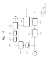
- FIG. 6 is a view illustrating a circulation path of the supercritical fluid.
- FIG. 7 is a view of a recycling unit of FIG. 6 according to an embodiment of the present invention.
- FIG. 8 is a view of a recycling unit of FIG. 6 according to another embodiment of the present invention.
- FIG. 9 is a sectional view of a separation module of FIG. 7 .
- FIG. 10 is a sectional view of a column module of FIG. 6 .
- FIG. 11 is a flowchart illustrating a process for treating a substrate according to an embodiment of the present invention.
- FIG. 12 is a flowchart illustrating a first process according to an embodiment of the present invention.
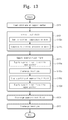
- FIG. 13 is a flowchart illustrating a second process according to an embodiment of the present invention.
- FIG. 14 is a view illustrating supplying and discharging of the supercritical fluid.
- FIG. 15 is a flowchart illustrating a process for treating a substrate according to another embodiment of the present invention.
- FIG. 16 is a graph illustrating efficiency of a separation unit.
- FIG. 17 is a table illustrating the efficiency of the separation unit.
- An apparatus 100 for treating a substrate according to the present invention may be an apparatus for performing a cleaning process on a substrata S.
- the substrate S can include various wafers including silicon wafers, glass substrates, organic substrates, and the like, as well as, substrates used for manufacturing semiconductor devices, displays, products including a thin film on which a circuit is formed, and the like.
- FIG. 1 is a plan view of the apparatus 100 for treating a substrate according to an embodiment of the present invention.
- the apparatus 100 for treating a substrate includes an index module 1000 , a process module 2000 , a supercritical fluid supply unit 3000 , and a recycling unit 4000 .
- the index module 1000 receives a substrate S from the outside to provide the substrate S into the process module.
- the process module 2000 performs a cleaning process on the substrate S.
- the supercritical fluid supply unit 3000 supplies a supercritical fluid to be used for the cleaning process, and the recycling unit 4000 recycles the supercritical fluid used in the cleaning process.
- the index module 1000 may be an equipment front end module (EFEM). Also, the index module 1000 includes a load port 1100 and a transfer frame 1200 . The load port 1100 , the transfer frame 1200 , and the process module 2000 may be successively arranged in a line.
- EFEM equipment front end module
- first direction X an arranged direction of the load port 1100 , the transfer frame 1200 , and the process module 2000 is referred to as a first direction X.
- second direction Y a direction perpendicular to the first direction X
- third direction Z a direction perpendicular to the first direction X and the second direction Y
- At least one load port 1100 may be provided in the index module 1000 .
- the load port 1100 is disposed on a side of the transfer frame 1200 .
- the load ports 1100 may be arranged in a line along the second direction Y.
- the number and arrangement of load ports 1100 are not limited to the above-described example.
- the number and arrangement of load ports 1100 may be adequately selected in consideration of a foot print of the apparatus 100 for treating a substrate, process efficiency, and a relative arrangement with respect to other apparatuses 100 for treating a substrate.
- a carrier C in which the substrate C is received is disposed on the load port 1100 .
- the carrier C is transferred from the outside and then loaded on the load port 1100 , or is unloaded from the load port 1100 and then transferred into the outside.
- the carrier C may be transferred between the apparatuses 100 for treating a substrate by a transfer unit such as an overhead hoist transfer (OHT).
- the substrate S may be transferred by the other transfer unit such as an automatic guided vehicle, a rail guided vehicle, or the like instead of the OHT, or a worker.
- a front opening unified pod may be used as the carrier C.
- At least one slot for supporting an edge of the substrate S may be provided within the carrier C.
- the slots may be spaced apart from each other along the third direction Z.
- the substrate S may be placed within the carrier C.
- the carrier C may receive twenty-five substrates S.
- the inside of the carrier C may be isolated from the outside by an openable door and thus be sealed. Thus, it may prevent the substrate S received in the carrier C from being contaminated.
- the transfer frame 1200 transfers the substrate S between the carrier C seated on the load port 1100 and the process module 2000 .
- the transfer module 1200 includes an index robot 1210 and an index rail 1220 .
- the index rail 1220 provides a movement path of the index robot 1210 .
- the index rail 1220 may be disposed in a length direction thereof parallel to the second direction Y.
- the index robot 1210 transfers the substrate S.
- the index robot 1210 may include a base 1211 , a body 1212 , and an arm 1213 .
- the base 1211 is disposed on the index rail 1220 . Also, the base 1211 may be moved along the index rail 1220 .
- the body 1212 is coupled to the base 1211 . Also, the body 1212 may be moved along the third direction Z on the base 1211 or rotated around an axis defined in the third direction Z.
- the arm 1213 is disposed on the body 1212 . Also, the arm 1213 may be moved forward and backward. A hand may be disposed on an end of the arm 1213 to pick up or place the substrate S.
- the index robot 1210 may include at least one arm 1213 . When the arm 1213 is provided in plurality, the arms 1213 may be stacked on the body 1212 and arranged in the third direction Z. Here, the arms 1213 may be independently operated.
- the base 1211 may be moved in the second direction Y on the index rail 1220 .
- the index robot 1210 may take the substrate S out of the carrier C to transfer the substrate S into the process module 2000 or take the substrate S out of the process module 2000 to receive the substrate S into the carrier C according to operations of the body 1212 and the arm 1213 .
- the index rail 1220 may be omitted in the transfer frame 1200 , and the index robot 1210 may be fixed to the transfer frame 1200 . In this case, the index robot 1210 may be disposed on a central portion of the transfer frame 1200 .
- the process module 2000 receives the substrate S from the index module 1000 to perform the cleaning process on the substrate S.
- the process module 2000 includes a buffer chamber 2100 , a transfer chamber 2200 , a first process chamber 2300 , and a second process chamber 2500 .
- the buffer chamber 2100 and the transfer chamber 2200 are disposed along the first direction X, and the transfer chamber 2200 is disposed in a length direction thereof parallel to the first direction X.
- the process chambers 2300 and 2500 may be disposed on a side surface of the transfer chamber 2200 in the second direction Y.
- the first process chamber 2300 may be disposed on one side of the transfer chamber 2200 in the second direction Y, and the second process chamber 2500 may be disposed on the other side opposite to the one side on which the first process chamber is disposed.
- the first process chamber 2300 may be provided in one or plurality.
- the first process chambers 2300 may be disposed on one side of the transfer chamber 2200 along the first direction X, stacked along the third direction Z, or disposed in combination thereof.
- the second process chamber 2500 may be provided in one or plurality.
- the second process chambers may be disposed on the other side of the transfer chamber 2500 along the first direction X, stacked along the third direction Z, or disposed in combination thereof.
- each of the chambers in the process module 2000 is not limited to the above-described example. That is, the chambers may be adequately disposed in consideration of process efficiency.
- the first and second process chambers 2300 and 2500 may be disposed along the first direction X on the same side surface as the transfer module 2200 or stacked on each other.
- the buffer chamber 2100 is disposed between the transfer frame 1200 and the transfer chamber 2200 to provide a buffer space in which the substrate S transferred between the index module 1000 and the process module 2000 is temporarily stayed. At least one buffer slots on which the substrate S is placed may be provided within the buffer chamber 2100 . When the buffer slot is provided in plurality, the buffer slots may be spaced apart from each other along the third direction Z.
- the substrate taken out of the carrier C by the index robot 1210 may be seated on the buffer slot, or the substrate C transferred from the process chambers 2300 and 2500 by the transfer robot 2210 of the transfer chamber 2200 may be seated on the buffer slot.
- the index robot 1210 or the transfer robot 2210 may take the substrate S out of the buffer slot to receive the substrate S into the carrier C or transfer the substrate S into the process chambers 2300 and 2500 .
- the transfer chamber 2200 transfers the substrate S between the chambers 2100 , 2300 , and 2500 disposed therearound.
- the buffer chamber 2100 may be disposed on one side of the transfer chamber 2200 in the first direction X.
- the process chambers 2300 and 2500 may be disposed on one side or both sides of the transfer chamber 2200 in the second direction Y.
- the transfer chamber 2200 may transfer the substrate S between the buffer chamber 2100 , the first process chamber 2300 , and the second process chamber 2500 .
- the transfer chamber 2200 includes a transfer rail 2220 and a transfer robot 2210 .
- the transfer rail 2220 provides a movement path of the transfer robot 2210 .
- the transfer rail 2220 may be disposed parallel to the first direction X.
- the transfer robot 2210 transfers the substrate S.
- the transfer robot 2210 includes a base 2211 , a body 2212 , and an arm 2213 . Since each of the components of the transfer robot 2210 is similar to each of those of the index robot 1210 , their detailed description will be omitted.
- the transfer robot 2210 transfers the substrate S between the buffer chamber 2100 , the first process chamber 2300 , and the second process chamber 2500 by the operations of the body 2212 and the arm 2213 while the base 2211 is moved along the transfer rail 2220 .
- the first and second process chambers 2300 and 2500 may perform processes different from each other on the substrate S.
- a first process performed in the first process chamber 2300 and a second process performed in the second process chamber 2500 may be successively performed.
- a chemical process, a cleaning process, and a first drying process may be performed in the first process chamber 2300 .
- a second drying process that is a subsequent process of the first process may be performed in the second process chamber 2500 .
- the first drying process may be a wet drying process performed using an organic solvent
- the second drying process may be a supercritical drying process performed using a supercritical fluid. As necessary, only one of the first and second drying processes may be selectively performed.
- FIG. 2 is a sectional view of the first process chamber 2300 of FIG. 1 .
- the first process is performed in the first process chamber 2300 .
- the first process may include at least one of the chemical process, the cleaning process, and the first drying process. As described above, the first drying process may be omitted.
- the first process chamber 2300 includes a housing 2310 and a process unit 2400 .
- the housing 2310 defines an outer wall of the first process chamber 230 , and the process unit 2400 is disposed within the housing 2310 to perform the first process.
- the process unit 2400 includes a spin head 2410 , a fluid supply member 2420 , a recovery container 2430 , and an elevation member 2440 .
- the substrate S is seated on the spin head 2410 . Also, the spin head 2410 rotates the substrate S during the progression of the processes.
- the spin head 2410 may include a support plate 2411 , a support pin 2412 , a chucking pin 2413 , a rotation shaft 2414 , and a motor 2415 .
- the support plate 2411 has an upper portion having a shape similar to that of the substrate S. That is, the upper portion of the support plate 2411 may have a circular shape.
- the plurality of support pins 2412 on which the substrate S is placed and the plurality of chucking pins 2413 for fixing the substrate S are disposed on the support plate 2411 .
- the rotation shaft 2414 rotated by the motor 2415 is fixed and coupled to a bottom surface of the support plate 2411 .
- the motor 2415 generates a rotation force using an external power source to rotate the support plate 2411 through the rotation shaft 2414 .
- the substrate S may be seated on the spin head 2410 , and the support plate 2411 may be rotated to rotate the substrate during the progression of the first process.
- Each of the support pins 2412 protrudes from a top surface of the support plate 2411 in the third direction Z.
- the plurality of support pins 2412 are disposed spaced a preset distance apart from each other.
- the support pins 2412 may be arranged in a circular ring shape.
- a back surface of the substrate S may be placed on the support pins 2412 .
- the substrate S is seated on the support pins 2412 so that the substrate S is spaced a protruding distance of each of the support pins 2412 apart from the top surface of the support plate 2411 by the support pins 2412 .
- Each of the chucking pins 2413 may further protrude from the top surface of the support plate 2411 than each of the support pins 2412 in the third direction Z. Thus, the chucking pins 2413 may be disposed farther away from a center of the support plate 2411 than the support pins 2412 .
- the chucking pins 2413 may be moved between a fixed position and a pick-up position along a radius direction of the support plate 2411 .
- the fixed position represents a position spaced a distance corresponding to a radius of the substrate S from the center of the support plate 2411
- the pick-up position represents a position away from the center of the support plate 2411 than the fixed position.
- the chucking pins 2413 are disposed at the pick-up position when the substrate S is loaded on the spin head 2410 by the transfer robot 2210 .
- the chucking pins 2413 may be moved to the fixed position to contact a side surface of the substrate S, thereby fixing the substrate S in a regular position.
- the chucking pins 2413 may be moved again to the pick-up position.
- the chucking pins 2413 may prevent the substrate S from being separated from the regular position by the rotation force when the spin head 2410 is rotated.
- the fluid supply member 2420 supplies a fluid onto the substrate S.
- the fluid supply member 2420 may include a nozzle 2421 , a support 2422 , a support shaft 2423 , and a driver 2424 .
- the support shaft 2423 is disposed so that a length direction thereof is parallel to the third direction Z.
- the driver 2424 is coupled to a lower end of the support shaft 2423 .
- the driver 2424 rotates the support shaft 2423 or vertically moves the support shaft 2423 along the third direction Z.
- the support 2422 is vertically coupled to an upper portion of the support shaft 2423 .
- the nozzle 2421 is disposed on a bottom surface of an end of the support 2422 .
- the nozzle 2421 may be moved between a process position and a standby position by the rotation and elevation of the support shaft 2423 through the driver 2424 .
- the process position represents a position at which the nozzle 2421 is disposed directly above the support plate 2411
- the standby position represents a position at which the nozzle 2421 is disposed deviational from the direct upper side of the support plate 2411 .
- At least one fluid supply member 2420 may be provided in the process unit 2400 .
- the fluid supply members 2420 may supply fluids different from each other, respectively.
- each of the plurality of fluid supply members 2420 may supply a detergent, a rinsing agent, or an organic solvent.
- the detergent may include a hydrogen peroxide (H 2 O 2 ) solution, a solution in which ammonia (NH 4 OH), hydrochloric acid (HCl), and sulfuric acid (H 2 SO 4 ) are mixed with the hydrogen peroxide (H 2 O 2 ) solution, or hydrofluoric acid (HF) solution.
- Deionized water may be mainly used as the rinsing agent.
- the organic solvent may include isopropyl alcohol, ethyl glycol, 1-propanol, tetrahydraulic franc, 4-hydroxyl, 4-methyl, 2-pentanone, 1-butanol, 2-butanol, methanol, ethanol, n-propyl alcohol, or dimethylether.
- a first fluid supply member 2420 a may spray the ammonia hydrogen peroxide solution
- the second fluid supply member may spray the deionized water
- the third fluid supply member 2420 c may spray the isopropyl alcohol solution.
- the organic solvent may be not in a liquid state, but in a gaseous state. If the organic solvent is provided in the gaseous state, the organic solvent may be mixed with an inert gas.
- the fluid supply member 2420 may be moved from the standby position to the process position to supply the above-described fluid onto the substrate S.
- the fluid supply member 2420 may supply the detergent, the rinsing agent, and the organic solvent to perform the chemical process, the cleaning process, and the first drying process, respectively.
- the spin head 2410 may be rotated by the motor 2415 to uniformly supply the fluids onto a top surface of the substrate S during the progression of the processes.
- the recovery container 2430 provides a space in which the first process is performed. Also, the recovery container 2430 recovers the fluid used for the first process. When viewed from an upper side, the recovery container 2430 is disposed around the spin head 2410 to surround the spin head 2410 and has an opened upper side. At least one recovery container 2430 may be provided in the process unit 2400 .
- the process unit 2400 including three recovery containers 2430 , i.e., a first recovery container 2430 a , a second recovery container 2430 b , and a third recovery container 2430 c will be described. However, the number of recovery containers 2430 may be differently selected according to the number of fluids and conditions of the first process.
- Each of the first, second, and third recovery containers 2430 a , 2430 b , and 2430 c may have a circular ring shape to surround the spin head 2410 .
- the first, second, and third recovery containers 2430 a , 2430 b , and 2430 c may be disposed away from a center of the spin head 2410 in an order of the first recovery container 2430 a , the second recovery container 2430 b , and the third recovery container 2430 c . That is, the first recovery container 2430 a surrounds the spin head 2410 , the second recovery container 2430 b surrounds the first recovery container 2430 a , and the third recovery container 2430 c surrounds the second recovery container 2430 b .
- inflow holes 2431 may be arranged in the third direction Z.
- the first recovery container 2430 a has a first inflow hole 2431 a defined by an inner space thereof.
- the second recovery container 2430 b has a second inflow hole 2431 b defined by a space between the first recovery container 2430 a and the second recovery container 2430 b .
- the third recovery container 2430 c has a third recovery container 2430 c defined by a space between the second recovery container 2430 b and the third recovery container 2430 c .
- a recovery line 2432 extending downward along the third direction Z is connected to a bottom surface of each of the first, second, and third recovery container 2430 a , 2430 b , and 2430 c .
- Each of the first, second, and third recovery lines 2432 a , 2432 b , and 2432 c discharges the fluids recovered into the first, second, and third recovery container 2430 a , 2430 b , and 2430 c to supply the fluids into an external fluid recycling system (not shown).
- the fluid recycling system (not shown) may recycle the recovered fluids to reuse the fluids.
- the elevation member 2440 moves the recovery container 2430 in the third direction Z.
- the recovery container 2430 may be changed in relative height with respect to the spin head 2410 .
- the inflow hole 2431 of one recovery container 2430 may be selectively adjusted in height so that the inflow hole 2431 is disposed on a horizontal plane of the substrate S seated on the spin head 2410 .
- the elevation member 2440 includes a bracket 2441 , an elevation shaft 2442 , and an elevator 2443 .
- the bracket 2441 is fixed to the recovery container 2430 .
- the bracket 2441 has one end fixed and coupled to the elevation shaft 2442 moved in the third direction Z by the elevator 2443 .
- the bracket 2441 may be coupled to the outermost recovery container 2430 .
- the elevation member 2440 may move the recovery container 2430 downward to prevent the recovery container 2430 from interfering with a path of the transfer robot 2210 for transferring the substrate S.
- the elevation member 2440 may move the recovery container 2430 in the third direction Z to locate the inflow hole 2431 of the recovery container 2430 on the same horizontal plane as the substrate S so that the fluid bouncing from the substrate S by a centrifugal force due to the rotation of the substrate S is recovered.
- the first, second, and third inflow holes 2431 a , 2431 b , and 2431 c may be moved to the same horizontal plane as the substrate S to recovery the fluids into the first, second, and third recovery containers 2430 a , 2430 b , and 2430 c when the detergent, the rinsing agent, and the organic solvent are supplied, respectively.
- the used fluids when the used fluids are recovered, environmental pollution may be prevented, and also, the expensive fluids may be recycled to reduce the semiconductor manufacturing costs.
- the elevation member 2440 may move the spin head 2410 in the third direction Z, instead of moving the recovery container 2430 .
- the second process is performed in the second process chamber 2500 .
- the second process may be a second drying process for drying the substrate S using a supercritical fluid.
- the supercritical fluid represents a fluid in a state in which a material exceeds a critical temperature and a critical pressure, i.e., a material is not classified into liquid and gaseous states by reaching a critical state.
- the supercritical fluid has a molecular density similar to that of liquid and viscosity similar to that of gas. Since the supercritical fluid has very high diffusion, penetration, and dissolution, the supercritical fluid has an advantage of chemical reaction. Also, since the supercritical fluid does not exert an interface tension to a fine structure due to a very low surface tension thereof, drying efficiency may be superior when the semiconductor device is dried, and pattern collapse may be prevented.
- a supercritical fluid of carbon dioxide (CO 2 ) mainly used for drying the substrate S will be described.
- CO 2 carbon dioxide
- the present invention is not limited to components and kinds of the supercritical fluid.
- FIG. 3 is a view illustrating a phase transition of carbon dioxide.
- carbon dioxide has a temperature of about 31.1° C. or more and a pressure of about 7.38 Mpa or more
- the carbon dioxide may become in a supercritical state.
- the carbon dioxide may be nonpoisonous, nonflammable, and inert properties.
- the supercritical carbon dioxide has a critical temperature and pressure less than those of other fluids.
- the supercritical carbon dioxide may be adjusted in temperature and pressure to easily control dissolution thereof.
- the supercritical carbon dioxide may have a diffusion coefficient less by about 10 times to about 100 times than that of the water or other solvents and a very low surface tension.
- the supercritical carbon dioxide may have physical properties suitable for performing the drying process.
- the carbon dioxide may be recycled from byproducts generated by various chemical reactions.
- the supercritical carbon dioxide used in the drying process may be circulated and reused to reduce environmental pollution.
- FIG. 4 is a sectional view of the second process chamber 2500 of FIG. 1 .
- the second process chamber 2500 includes a housing 2510 , a heating member 2520 , a support member 2530 , a supercritical fluid supply tube 2540 , and an exhaust tube 2550 .
- the inside of the housing 2510 may provide a space which is sealed from the outside to dry the substrate S.
- the housing 2510 may be formed of a material enough to endure a high pressure.
- the heating member 2520 for heating the inside of the housing 2510 may be disposed between an inner wall and an outer wall of the housing 2510 .
- the present invention is not limited to a position of the heating member 2520 .
- the heating member 2520 may be disposed at a position different from the above-described position.
- the support member 2530 supports the substrate S.
- the support member 2530 may be fixed and installed within the housing 2510 .
- the support member 2530 may not be fixed, but be rotated to rotate the substrate S seated on the support member 2530 .
- the supercritical fluid supply tube 2540 supplies a supercritical fluid into the housing 2510 .
- the supercritical fluid supply tube 2540 includes at least one of an upper supply tube 2540 a and a lower supply tube 2540 b .
- the upper supply tube 2540 a is connected to an upper portion of the housing 2510 and the supercritical fluid supply unit 3000 .
- the lower supply tube 2540 b is connected to a lower portion of the housing 2510 and the supercritical fluid supply unit 3000 .
- Each of the upper supply tube 2540 a and the lower supply tube 2540 b may include a valve V for adjusting a flow rate of the supercritical fluid.
- the valve V may be a switching valve or a flow control valve.
- the supercritical fluid may be supplied into the housing 2510 through at least one of the upper and lower supply tubes 2540 a and 2540 b according to the progression of the second drying process.
- the lower supply tube 2540 b may be branched from the upper supply tube 2540 b .
- the upper and lower supply tubes 2540 a and 2540 b may be connected to the same supercritical fluid supply unit 3000 .
- the upper and lower supply tubes 2540 a and 2540 b may be connected to the supercritical fluid supply units 3000 different from each other, respectively.
- the supercritical fluid within the housing 2510 may be discharged through the discharge tube 2550 .
- a valve V may be disposed in the discharge tube 2550 .
- the discharge tube 2550 may be disposed under the housing 2510 .
- the discharge tube 2550 may be disposed above the housing 2510 .
- FIG. 5 is a sectional view of the second process chamber 2500 of FIG. 1 according to another embodiment.
- the second process chamber 2500 according to another embodiment may further include a gas supply tube 2560 .
- the gas supply tube 2560 supplies an inert gas into the housing 2510 .
- the inert gas may include N2, He, Ne, and Ar.
- the gas supply tube 2560 is connected to the housing 2510 and a gas supply source G.
- the gas supply tube 2560 may be connected to an upper portion of the housing 2510 .
- a valve V for regulating a flow rate may be disposed in the gas supply tube 2560 .
- the inert gas may be discharged through the discharge tube 2550 .
- two discharge tubes 2550 a and 2550 b may be provided to the second process chamber 2500 .
- the supercritical fluid may be discharged through the first discharge tube 2550 a
- the inert gas may be discharged through the second discharge tube 2550 b.
- the number and arrangement of the supercritical fluid supply tube 2540 , the gas supply tube 2560 , and the discharge tube 2550 may be changed in consideration of the process efficiency, the foot print, and the like.
- the supercritical fluid supply tube 2540 or the discharge tube 2550 may be disposed on a side surface of the housing 2510 .
- the first discharge tube 2550 a may be connected to a lower portion of the housing 2510
- the second discharge tube 2550 b may be connected to an upper portion of the housing 2510 .
- the second drying process using the supercritical fluid may be performed in the second process chamber 2500 .
- the second drying process using the supercritical fluid may be performed on the substrate S on which the chemical process, the cleaning process, and the first drying process using the organic solvent are successively performed.
- the heating member 2520 heats the inside of the housing 2510 , and the supercritical fluid is supplied through the supercritical fluid supply tube 2540 .
- a supercritical fluid atmosphere may be formed within the housing 2510 .
- the supercritical fluid may dissolve the organic solvent remaining on the substrate S because the organic solvent is not completely dried after the organic solvent is used in the first drying process which is performed lastly in the first process chamber 2300 .
- the supercritical fluid is discharged through a discharge hole. Then, the substrate S is unloaded from the support member 2530 by the transfer robot 2210 to take out.
- the supercritical fluid supply unit 3000 supplies a supercritical fluid into the second process chamber 2500 , and the recycling unit 4000 recycles the supercritical fluid used in the second process chamber 2500 to supply the recycled supercritical fluid into the supercritical fluid supply unit 3000 .
- the supercritical fluid supply unit 3000 and the recycling unit 4000 may be realized as independent separate devices or the whole or a portion of the supercritical fluid supply unit 3000 and the recycling unit 4000 may be included in the apparatus 100 for treating a substrate as one component.
- the supercritical fluid may have different components.
- FIG. 6 is a view illustrating a circulation path of the supercritical fluid.
- the supercritical fluid may be recycled while being circulated in the supercritical fluid supply unit 3000 , the second process chamber 2500 , and the recycling unit 4000 .
- the supercritical fluid supply unit 3000 may include a storage tank 3100 , a water supply tank 3200 , a first condenser 3300 , a second condenser 3400 , and a pump 3500 .
- Carbon dioxide is stored in the storage tank 3100 in a liquid state.
- the carbon dioxide may be supplied from the outside or the recycling unit 400 and then stored in the storage tank 3100 .
- the carbon dioxide supplied from the outside or the recycling unit 4000 may be in a gaseous sate.
- the first condenser 3300 changes the gaseous carbon dioxide into liquid carbon dioxide to store the liquid carbon dioxide in the storage tank 3100 . Since the liquid carbon dioxide has a volume less than that of the gaseous carbon dioxide, a large amount of carbon dioxide may be stored in the storage tank 3100 .
- the water supply tank 3200 receives the carbon dioxide from the storage tank 3100 to change the carbon dioxide into the supercritical fluid state. Then, the supercritical fluid is supplied into the second process chamber 2500 of the process module 2000 .
- the carbon dioxide stored in the storage tank 3100 is moved into the water supply tank 3200 while being changed into a gaseous state when the valve V connecting the storage tank 3100 to the water supply tank 3200 is opened.
- the second condenser 3400 and the pump 3500 may be disposed in the line connecting the storage tank 3100 to the water supply tank 3200 .
- the second condenser 3400 changes the carbon dioxide having the gases state into carbon dioxide having a liquid state.
- the pump 3500 changes the liquid carbon dioxide into gases carbon dioxide compressed over a critical pressure to supply the gases carbon dioxide into the water supply tank 3200 .
- the water supply tank 3200 may heat the supplied carbon dioxide at a temperature over a critical temperature to produce the supercritical fluid, and then transfer the supercritical fluid into the second process chamber 2500 .
- the carbon dioxide discharged from the water supply tank 3200 may be in a state which the carbon dioxide is compressed at a pressure of about 100 bar to about 150 bar.
- the water supply tank 3200 may supply the liquid or gaseous carbon dioxide into the second process chamber 2500 .
- FIG. 7 is a view of the recycling unit of FIG. 6 according to an embodiment of the present invention
- FIG. 8 is a view of a recycling unit 4000 of FIG. 6 according to another embodiment of the present invention.
- the recycling unit 4000 recycles the supercritical fluid containing an organic solvent used for the second drying process in the second process chamber 2500 to supply the recycled supercritical fluid into the supercritical fluid supply unit 3000 .
- the recycling unit 4000 may include at least one of a separation module 4100 and a column module 4200 .
- the separation module 4100 cools carbon dioxide to liquefy the organic solvent contained in the carbon dioxide, thereby separating the organic solvent from the carbon dioxide.
- the column module 4200 allows the carbon dioxide to pass through a space in which an absorption material A for absorbing the organic solvent is disposed to separate the organic solvent from the carbon dioxide.
- a plurality of separation modules 4100 may be provided in the recycling unit 4000 .
- the separation modules 4100 may be connected to each other in series.
- the first separation module 4100 a is connected to the second process chamber 2500 to separate the carbon dioxide and the organic solvent from each other firstly.
- the second separation module 4100 b is connected to the first separation module 4100 a to separate the carbon dioxide and the organic solvent from each other secondly.
- the separation of the carbon dioxide and the organic solvent by the separation module 4100 may be performed several times to obtain more pure carbon dioxide.
- a plurality of column modules 4200 may be provided in the recycling unit 4000 .
- the column modules 4200 may be connected to each other in series.
- the separation of the carbon dioxide and the organic solvent by the column modules 4200 may be performed several times.
- the first column module 4200 a is connected to the separation module 4100 to filter the organic solvent from the carbon dioxide firstly.
- the second column module 4200 b is connected to the first column module 4200 a to filter the organic solvent from the carbon dioxide secondly.
- the column modules 4200 may be connected parallel to each other. Here, it may take a long time to separate the organic solvent using the column module 4200 . Also, it may be difficult to filter a large amount of carbon dioxide using the column module 4200 . However, when the plurality of column module are disposed parallel to each other, a large amount of carbon dioxide may be filtered.
- each of the first, second, and third column modules 4200 a , 4200 b , and 4200 c is connected to the separation module 4100 to filter the organic solvent from the carbon dioxide, thereby providing the carbon dioxide into the supercritical fluid supply unit 3000 .
- FIG. 9 is a sectional view of the separation module 4100 of FIG. 8 .
- the separation module 4100 may include a separation tank 4110 , a cooling member 4120 , an inflow tube 4130 , an exhaust tube 4140 , a drain tube 4150 , and a pressure regulator 4160 .
- the separation tank 4110 provides a space in which the carbon dioxide and the organic solvent are separated from each other.
- the cooling member 4120 is disposed between an inner wall and an outer wall of the separation tank 4110 to cool the separation tank 4110 .
- the cooling member 4120 may be realized as a pipe line through which cooling water flows.
- the carbon dioxide discharged from the second process chamber 2500 is introduced into the inflow tube 4130 .
- the carbon dioxide discharged from the former separation module 4100 may be introduced into the inflow tube 4130 .
- the inflow tube 4130 has one end through which the carbon dioxide is supplied into a lower portion of the separation tank 4110 .
- the carbon dioxide supplied into the lower portion of the separation tank 4110 is cooled by the cooling member 4120 .
- an organic solvent contained in the carbon dioxide is liquefied to separate the organic solvent from the carbon dioxide.
- the separated carbon dioxide is discharged through the exhaust tube 4140 connected to an upper portion of the separation tank 4110 , and the liquid organic solvent is discharged through the drain tube 4150 connected to a lower portion of the separation tank 4110 .
- a valve V may be disposed in each of the inflow tube 4130 , the exhaust tube 4140 , and the drain tube 4150 to control the inflow and discharge.
- the pressure regulator 4160 regulates an internal pressure of the separation tank 4110 .
- the pressure regulator 4160 may be a reverse pressure regulator disposed in the exhaust tube 4140 .
- FIG. 10 is a view of the column module 4200 of FIG. 6 .
- the column module 4200 may include an absorption column 4210 , a temperature maintenance member 4220 , an inflow tube 4230 , an exhaust tube 4240 , and a concentration sensor 4250 .
- the absorption column 4210 provides a space in which an organic solvent is separated from carbon dioxide.
- An absorption material A is disposed within the absorption column 4210 .
- the absorption material A may be a material for absorbing the organic solvent.
- the absorption material A may be zeolite.
- the carbon dioxide is introduced into the absorption column through the inflow tube 4230 .
- the inflow tube 4230 may be connected to the separation module 4100 .
- the inflow tube 4230 may be connected to the former column module 4200 .
- the carbon dioxide passes through the absorption column 4210 and is discharged into the exhaust tube 4240 .
- the absorption material A is provided to carbon dioxide while the carbon dioxide passes through the absorption column 4210 to absorb an organic solvent from the carbon dioxide. Accordingly, the organic solvent contained in the carbon dioxide is removed to recycle the carbon dioxide. When the carbon dioxide and the organic solvent are separated from each other, heat may occur. Thus, the temperature maintenance member 4220 may maintain the inside of the absorption column 4210 at a predetermined temperature so that the organic solvent is easily separated from the carbon dioxide.
- the concentration sensor 4250 may detect a concentration of the organic solvent contained in the carbon dioxide discharged from the absorption column 4210 .
- the concentration sensor 4250 is disposed in the exhaust tube 4240 .
- the concentration sensor 4250 may be disposed in only the last absorption column 4210 .
- the concentration sensor 4250 may be disposed in each of the absorption columns 4210 . Since an amount of organic solvent capable of being absorbed by the absorption material A is limited, when the organic solvent contained in the carbon dioxide discharged through the concentration sensor 4250 has a concentration greater than a preset concentration, the absorption material A may be replaced.
- the carbon dioxide discharged from the column module 4200 is supplied into the supercritical fluid supply unit 3000 .
- the column module 4200 is connected to the separation module 4100 in the recycling unit 4000 in the current embodiment, the present invention is not limited thereto.
- the separation module 4100 is omitted in the recycling unit 4000
- the column module 4200 may be directly connected to the second process chamber 2500 .
- the substrate treatment method, the supercritical fluid recycling method, and the supercritical fluid discharge method according to the present invention may be performed using other substrate treatment apparatuses capable of performing a function equal or similar to that of the substrate treatment apparatus 100 , except for the apparatus 100 for treating a substrate according to the present invention.
- FIG. 11 is a flowchart illustrating a substrate treatment method according to an embodiment of the present invention.
- the substrate treatment method according to the embodiment of the present invention may be a cleaning process using a supercritical fluid.
- the substrate treatment method includes transferring a substrate S from a carrier C seated on a load port 1100 into a buffer chamber 2100 (S 110 ), transferring the substrate S from the buffer chamber 2100 into a first process chamber 2300 (S 120 ), performing a first process (S 130 ), transferring the first process chamber 2300 into a second process chamber 2500 (S 140 ), performing a second process (S 150 ), transferring the substrate S from the second process chamber 2500 into the buffer chamber 2100 (S 160 ), and transferring the substrate S from the buffer chamber 2100 into the carrier C ( 170 ).
- S 110 transferring the substrate S from a carrier C seated on a load port 1100 into a buffer chamber 2100
- S 120 transferring the substrate S from the buffer chamber 2100 into a first process chamber 2300
- S 130 performing a first process
- S 130 transferring the first process chamber 2300 into a second process chamber 2500
- S 150 performing a second process
- an index robot 1210 transfers the substrate S from the carrier C into the buffer chamber 2100 .
- the carrier C receiving the substrate S transferred from the outside is placed on the load port 1100 .
- a carrier opener (not shown) or the index robot 1210 opens a door of the carrier C so that the index robot 1210 takes the substrate S out of the carrier C. Then, the index robot 1210 transfers the substrate taken out of the carrier C into the buffer chamber 2100 .
- the transfer robot 2210 transfers the substrate S from the buffer chamber 2100 into the first process chamber 2300 .
- a transfer robot 2210 takes the substrate S out of the buffer slot.
- the transfer robot 2210 transfers the substrate S into the first process chamber 2300 .
- FIG. 12 is a flowchart illustrating a first process according to an embodiment of the present invention.
- the substrate S is placed on a support pin 2412 by the transfer robot 2210 and loaded on a spin head 2410 .
- a chucking pin 2413 is moved from a pick-up position to a fixing position to fix the substrate S.
- a fluid supply member 2420 supplies a fluid onto the substrate S in operation S 132 .
- the spin head 2410 is rotated to rotate the substrate S while the fluid is supplied onto the substrate S.
- the fluid may be uniformly supplied onto an entire surface of the substrate S.
- a recovery container 2430 may be vertically moved to recover the fluid bouncing from the substrate S by the rotation of the substrate S after the fluid is supplied onto the substrate S.
- a first fluid supply member 2420 a is moved from a standby position to a process position to spray a first detergent onto the substrate S in operation S 132 a (a first chemical process).
- a first inflow hole 2431 a of the first recovery container 2430 a may be moved to the same horizontal plane as the substrate S to recover the first detergent.
- operation S 132 b (a first cleaning process)
- the first fluid supply member 2420 a is moved to the standby position, and a second fluid supply member 2420 b is moved from the standby position to the process position to spray a rinsing agent.
- residues of the first detergent remaining on the substrate S may be cleaned.
- a second inflow hole 2431 b of a second recovery container 2430 b may be moved to the same horizontal plane as the substrate S to recover the rinsing agent.
- the second fluid supply member 2420 b returns to the standby position, and a third fluid supply member 2420 c is moved from the standby position to the process position to spray an organic solvent.
- the rinsing agent remaining on the substrate S may be substituted for the organic solvent.
- a third inflow hole 2431 c of the third recovery container 2430 c may be moved to the same horizontal plane as the substrate S to recover the organic solvent.
- the organic solvent may be supplied in a state where the organic solvent in heated at a temperature greater than room temperature or in a heated vapor state.
- the spin head 2410 may rotate the substrate S so that the organic solvent is easily dried after the spray of the organic solvent is finished.
- a process (a second chemical process) in which a fourth fluid supply member 2420 d sprays a second detergent and a process (a second cleaning process) in which the second fluid supply member 2420 b sprays the rinsing agent again may be additionally performed between the operation S 132 b and the operation S 132 c .
- the first and second detergents may be provided as components different from each other to effectively remove foreign substances different from each other, respectively.
- the operation S 132 c may be omitted as necessary.
- the rotation of the spin head 2410 may be finished, and the chucking pin 2413 may be moved from the fixed position to the pick-up position.
- the substrate S may be picked up by the transfer robot 2210 and unloaded from the spin head 2410 .
- the transfer robot 2210 transfers the substrate S from the first process chamber 2300 into the second process chamber 2500 .
- the transfer robot 2210 picks up the substrate S seated on the spin head 2140 to take the substrate out of the first process chamber 2300 .
- the transfer robot 2210 transfers the substrate S into the second process chamber 2500 .
- the substrate S transferred into the second process chamber 2500 is seated on the support member 2530 .
- FIG. 13 is a flowchart illustrating the second process according to an embodiment of the present invention.
- the substrate S is loaded on the support member 2530 of the second process chamber 2500 .
- a critical sate is formed within a housing 2510 after and before the substrate S is loaded.
- the critical state may represent a state in which a temperature and pressure exceed a critical temperature and critical pressure, respectively.
- a heating member 2520 heats the inside of the housing 2510 to form the critical state.
- the inside of the housing 2510 may be increased to a temperature greater than the critical temperature.
- an inert gas is introduced into the housing 2510 through a gas supply tube 2560 .
- the inside of the housing 2510 may be filled with the inert gas, and be increased to a pressure greater than the critical pressure.
- a supercritical fluid is supplied into the housing 2510 through a supercritical fluid supply tube 2540 in operation S 153 .
- the operation S 153 may be performed as follows.
- the supercritical fluid may be supplied from a lower portion of the housing 2510 through a lower supply tube 2540 b .
- the inert gas may be discharged to the outside through a discharge tube 2550 .
- the inside of the housing 2510 may be filled with only the supercritical fluid to form a supercritical fluid phenomenon.
- the supply of the supercritical fluid through the lower supply tube 2540 b is stopped in operation S 153 c to supply the supercritical fluid through an upper supply tube 2540 a in operation S 153 d .
- the drying of the substrate S using the supercritical fluid may be quickly performed.
- the substrate S since the inside of the housing 2510 is in the critical state, the substrate S may be less damaged or not be damaged even though the supercritical fluid is directly sprayed at a high speed onto the substrate S.
- the supercritical fluid is discharged in operation S 154 .
- the inert gas may be supplied into the housing 2510 to discharge the supercritical fluid.
- FIG. 14 is a view illustrating supplying and discharging of the supercritical fluid.
- the supercritical fluid may be supplied in the operation 5153 until the inside of the housing 2510 has a pressure of about 150 bar, and then the supercritical fluid may be discharged until the inside of the housing 2510 has a pressure of about 100 bar.
- the two operations S 153 and 154 may be repeatedly performed to increase the drying efficiency.
- the operation S 153 may be performed for a long time to dry the substrate S.
- the inert gas is discharged to decrease an internal pressure of the housing 2510 in operation S 155 .
- the second drying process is performed using the inert gas in the current embodiment, the present invention is not limited thereto.
- the second drying process may be performed using only the supercritical fluid without the inert gas.
- liquid carbon dioxide may be supplied first, and then, the liquid carbon dioxide may be continuously heated to change the liquid carbon dioxide into gaseous carbon dioxide. Then, the gaseous carbon dioxide may be compressed to form the supercritical atmosphere.
- the transfer robot 2210 transfers the substrate S from the second process chamber 2500 into the buffer chamber 2100 .
- the transfer robot 2210 unloads the substrate S from the support member 2530 to take the substrate S out of the second process chamber 2500 , thereby mounting the substrate S on the buffer slot of the buffer chamber 2100 .
- a portion of the substrates or the whole substrates may be transferred by arms 2213 of transfer robots 2210 different from each other.
- the substrate S may be transferred by arms 2213 of the transfer robots 2210 different from each other.
- the substrate S may be transferred by the same arm 2213 in the operations S 120 and 140 , and the substrate S may be transferred by a different arm 2213 in the operation S 160 .
- the transferred substrate S may be a substrate S before the cleaning process is performed.
- the substrate S may be a substrate which is not dried. That is, the foreign substances, the detergent, the rinsing agent, or the organic solvent may remain on the substrate S, and thus, the hand of the arm 2213 may be contaminated by the above-described materials.
- the substrate S may be contaminated again.
- the index robot 1210 transfers the substrate C from the buffer chamber 2100 into the carrier C.
- the index robot 1210 holds the substrate S mounted on the buffer slot to mount the substrate on a slot of the carrier C.
- the operation S 190 may be performed using an arm 1213 different from the arm 1213 used in the operation 5110 . Thus, as described above, it may prevent the substrate S from being contaminated.
- the carrier C may be transferred to the outside by an overhead hoist transfer (OHT).
- OHT overhead hoist transfer
- FIG. 15 is a flowchart illustrating a process for treating a substrate according to another embodiment of the present invention.
- the substrate treatment method according to another embodiment of the present invention may be a cleaning process using a supercritical fluid.
- the supercritical fluid recycling method includes storing carbon dioxide (S 210 ), changing the carbon dioxide into a supercritical fluid (S 220 ), performing a drying process using the supercritical fluid (S 230 ), recycling the carbon dioxide (S 240 ), and storing the recycled carbon dioxide (S 250 ).
- S 210 carbon dioxide
- S 220 changing the carbon dioxide into a supercritical fluid
- S 230 performing a drying process using the supercritical fluid
- S 240 recycling the carbon dioxide
- S 250 storing the recycled carbon dioxide
- carbon dioxide is stored in a storage tank 3100 .
- the carbon dioxide is received from an external carbon dioxide supply source F or a recycling unit 4000 and stored in a liquid state.
- the carbon dioxide may be received in a gaseous state.
- a first condenser 3300 may change the gaseous carbon dioxide into the liquid carbon dioxide to supply the liquid carbon dioxide into the storage tank 3100 .
- a water supply tank 3200 changes the carbon dioxide into a supercritical fluid.
- the water supply tank 3200 may receive the carbon dioxide from the storage tank 3100 to change the carbon dioxide into the supercritical fluid.
- the carbon dioxide is discharged from the storage tank 3100 and moved into the water supply tank 3200 .
- the carbon dioxide may be changed into the gaseous carbon dioxide by a change of a pressure.
- a second condenser 3400 and a pump 3500 are disposed in a line connecting the storage tank 3100 and the water supply tank 3200 .
- the second condenser 3400 changes the gaseous carbon dioxide into the liquid carbon dioxide
- the pump 3500 changes the liquid carbon dioxide into high-pressure gaseous carbon dioxide to supply the high-pressure gaseous carbon dioxide into the water supply tank 3200 .
- the water supply tank 3200 heats the high-pressure gaseous carbon dioxide to produce a supercritical fluid.
- the water supply tank 3200 provides the supercritical fluid into the second process chamber 2500 .
- the second process chamber 2500 performs a drying process using the supercritical fluid.
- the second process chamber 2500 receives the supercritical fluid from the water supply tank 3200 to dry the substrate S using the supercritical fluid.
- the drying process may be the above-described second drying process.
- the second process chamber 2500 discharges the supercritical fluid during or after the drying process.
- the recycling unit 4000 recycles the carbon dioxide.
- a separation module 4100 cools the discharged supercritical fluid to separate an organic solvent from the supercritical fluid.
- a cooling member 4120 cools the supercritical fluid to liquefy the organic solvent dissolved in the supercritical fluid, thereby separating the organic solvent.
- the organic solvent is discharged through a drain tube 4150 disposed at a lower portion of the separation tank 4110 , and the carbon dioxide separated from the organic solvent is separated through an upper exhaust tube 4140 disposed at an upper portion of the separation tank 4110 .
- an internal temperature of the separation tank 4110 is important.
- FIG. 16 is a graph illustrating efficiency of the separation unit 4100
- FIG. 17 is a table illustrating the efficiency of the separation unit 4100
- FIGS. 16 and 17 illustrate an amount and efficiency of an organic solvent drained when the separation tank 4110 has internal temperatures of about 10° C., about 20° C., and about 30° C. As described above, when the operation S 241 is performed at a temperature of about 10° C., it is seen that separation efficiency is improved by about 10% when compared that the operation S 241 is performed at a temperature of about 30° C.
- a column module 4200 separates the organic solvent again from the carbon dioxide in which the organic solvent is separated primarily by the separation module 4100 .
- the supercritical fluid or the gaseous carbon dioxide is introduced through the inflow tube 4230 to pass through an absorption column 4210 , and then is discharged into an exhaust tube 4240 .
- the carbon dioxide passes through an absorption material A.
- the organic solvent dissolved in the carbon dioxide is absorbed into the absorption material A.
- the organic solvent is separated, and pure carbon dioxide is discharged through the exhaust tube 4240 . Therefore, the carbon dioxide may be recycled through the above-described processes.
- the recycling unit 4000 provides the recycled carbon dioxide into the storage tank 3100 .
- the carbon dioxide is moved and stored into the storage tank 3100 .
- the carbon dioxide discharged from the recycling unit 4000 is in gaseous state.
- the gaseous carbon dioxide is changed into liquid carbon dioxide by the first condenser 3300 and stored in the storage tank 3100 .
- each embodiment may selectively include the above-described processes.
- the embodiments may be realized by being separated from or combined with each other.
- the processes performed in each embodiment may be realized by separating or combining the processes performed in the other embodiment from or with each other.
- the substrate treatment method according to the present invention may be stored in a computer readable recording medium with a code or program for executing the substrate treatment method.
- the substrate may be dried using the supercritical fluid.
- the substrate may be dried using the supercritical fluid to efficiently perform the drying process and prevent the substrate from being damaged.
- the supercritical fluid used in the drying process may be recycled.
- the supercritical fluid is cooled to separate the organic solvent.
- the absorption material for absorbing the organic solvent may be used to separate the organic solvent form the fluid which is provided as the supercritical fluid.
- the supercritical fluid may be reused again in the drying process to reduce manufacturing costs and prevent the environmental pollution from occurring.
Landscapes
- Cleaning Or Drying Semiconductors (AREA)
Abstract
Description
- This U.S. non-provisional patent application claims priority under 35 U.S.C. §119 of Korean Patent Application Nos. 10-2011-0064987, filed on Jun. 30, 2011, and 10-2011-0104768, filed on Oct. 13, 2011, the entire contents of which are hereby incorporated by reference.
- The present disclosure herein relates to an apparatus and method for treating a substrate, and more particularly, to an apparatus and method for treating a substrate using a supercritical fluid.
- Semiconductor devices are manufactured through various processes including a photolithography process for forming circuit patterns on a substrate such as a silicon wafer or the like. When the semiconductor devices are manufactured, various foreign substances such as particles, organic contaminants, metal impurities, and the like may be generated. The foreign substances may cause substrate defects to directly exert a bad influence on yield of semiconductor devices. Thus, a cleaning process for removing the foreign substances may be essentially involved in a semiconductor manufacturing process.
- Generally, in a typical cleaning process, foreign substances remaining on a substrate are removed using detergent and then the substrate is cleaned using deionized water (DI-water) to dry the cleaned substrate using isopropyl alcohol (IPA). However, the drying process may have low efficiency in a case where a semiconductor device has fine circuit patterns. In addition, since damage of the circuit patterns, i.e., pattern collapse frequently occurs during the drying process, the drying process is unsuitable for a semiconductor device having a line width of about 30 nm or less.
- Thus, to solve the above-described limitation, studies about technologies for drying a substrate using a supercritical fluid are actively being carried out.
- The present invention provides an apparatus for treating a substrate using a supercritical fluid and a method for treating the substrate using the same.
- The present invention also provides an apparatus for treating a substrate in which a supercritical fluid used for drying the substrate is recycled and a method for treating the substrate using the same.
- The feature of the present invention is not limited to the aforesaid, but other features not described herein will be clearly understood by those skilled in the art from this specification and the accompanying drawings.
- The prevent invention provides an apparatus for treating a substrate.
- Embodiments of the present invention provide apparatuses for treating a substrate, the apparatuses including: a process chamber in which an organic solvent remaining on a substrate is dissolved using a fluid provided as a supercritical fluid to dry the substrate; and a recycling unit in which the organic solvent is separated from the fluid discharged from the process chamber to recycle the fluid.
- In some embodiments, the recycling unit may include a separation module for cooling the fluid in which the organic solvent is dissolved to separate the organic solvent from the fluid.
- In other embodiments, the separation module may be provided in plurality, and the plurality of separation modules may be connected to each other in series.
- In still other embodiments, the separation module may include: a separation tank in which the fluid discharged from the process chamber is introduced; a cooling member for cooling the separation tank; a drain tube disposed in a lower portion of the separation tank to discharge the organic solvent liquefied and separated from the fluid; and a first exhaust tube disposed in an upper portion of the separation tank to discharge the fluid from which the organic solvent is separated.
- In even other embodiments, the separation module may further include an inflow tube for supplying the fluid discharged from the process chamber into the lower portion of the separation tank.
- In yet other embodiments, the separation module may further include a reverse pressure regulator disposed in the first exhaust tube to constantly maintain an internal pressure of the separation tank.
- In further embodiments, the recycling unit may further include a column module providing an absorption material for absorbing the organic module into the fluid discharged from the separation module to separate the organic solvent from the fluid, the column module may be provided in plurality, and the plurality of column modules may be connected to each other in series.
- In still further embodiments, the column module may be provided in plurality, and the plurality of column modules may be connected parallel to each other.
- In even further embodiments, the column module may include: an absorption column for providing the absorption material into the fluid discharged from the separation module; a temperature maintenance member for constantly maintaining an internal temperature of the absorption column; and a second exhaust tube for discharging the fluid from which the organic solvent is separated by the absorption material.
- In yet further embodiments, the column module may further include a concentration sensor disposed in the second exhaust tube to detect a concentration of the organic solvent contained in the fluid discharged from the second exhaust tube.
- In much further embodiments, the absorption material may include zeolite.
- In still much further embodiments, the recycling unit may include a column module providing an absorption material for absorbing the organic module into the fluid discharged from the process chamber to separate the organic solvent from the fluid.
- In other embodiments of the present invention, methods for treating a substrate include: dissolving an organic solvent remaining on the substrate using a fluid provided as a supercritical fluid to dry the substrate; and separating the organic solvent from the fluid to recycle the fluid.
- In some embodiments, the recycling of the fluid may include cooling the fluid in which the organic solvent is dissolved to separate the organic solvent from the fluid.
- In other embodiments, the recycling of the fluid may further include providing an absorption material for absorbing the organic solvent into the fluid to separate the organic solvent from the fluid.
- In still other embodiments of the present invention, apparatuses for treating a substrate include: a process chamber in which an organic solvent remaining on the substrate is dissolved using a fluid provided as a supercritical fluid to dry the substrate; a storage tank in which the fluid is stored in a liquid state; a water supply tank receiving the fluid from the storage tank to produce the supercritical fluid and provide the supercritical fluid into the process chamber; and a recycling unit in which the organic solvent is separated from the fluid discharged from the process chamber to recycle the fluid and supply the recycled fluid into the storage tank.
- In some embodiments, the recycling unit may include a separation module for cooling the fluid in which the organic solvent is dissolved to separate the organic solvent from the fluid.
- In other embodiments, the recycling unit may further include a column module providing an absorption material for absorbing the organic module into the fluid discharged from the separation module to separate the organic solvent from the fluid.
- In still other embodiments, the apparatuses may further include a first condenser for changing the gaseous fluid discharged from the recycling unit into a liquid fluid to supply the liquid fluid into the storage tank
- In even other embodiments, the apparatuses may further include: a second condenser for changing the gaseous fluid discharged from the storage tank into the liquid fluid; and a pump receiving the liquid fluid from the second condenser to supply the liquid fluid into the water supply tank, and wherein, in the water supply tank, the fluid compressed at a pressure greater than a critical pressure by the pump is heated at a temperature greater than a critical temperature to produce the supercritical fluid.
- In even other embodiments of the present invention, methods for treating a substrate include: storing a liquid fluid into a storage tank; changing the stored fluid into a supercritical fluid; dissolving an organic solvent remaining on the substrate using the fluid provided as the supercritical fluid to dry the substrate; separating the organic solvent from the fluid in which the organic solvent is dissolved to recycle the fluid; and changing the recycled fluid into a liquid fluid to supply the liquid fluid into the storage tank.
- In some embodiments, the recycling of the fluid may include a first recycling process of cooling the fluid in which the organic solvent is dissolved to separate the organic solvent from the fluid.
- In other embodiments, the recycling of the fluid may further include a second recycling process of providing an absorption material for absorbing the organic solvent into the fluid to separate the organic solvent from the fluid.
- The accompanying drawings are included to provide a further understanding of the present invention, and are incorporated in and constitute a part of this specification. The drawings illustrate exemplary embodiments of the present invention and, together with the description, serve to explain principles of the present invention. In the drawings:
-
FIG. 1 is a plan view of an apparatus for treating a substrate according to an embodiment of the present invention; -
FIG. 2 is a sectional view of a first process chamber ofFIG. 1 ; -
FIG. 3 is a view illustrating a phase transition of carbon dioxide. -
FIG. 4 is a sectional view of a second process chamber ofFIG. 1 ; -
FIG. 5 is a sectional view of a second process chamber ofFIG. 1 according to another embodiment of the present invention; -
FIG. 6 is a view illustrating a circulation path of the supercritical fluid. -
FIG. 7 is a view of a recycling unit ofFIG. 6 according to an embodiment of the present invention; -
FIG. 8 is a view of a recycling unit ofFIG. 6 according to another embodiment of the present invention; -
FIG. 9 is a sectional view of a separation module ofFIG. 7 . -
FIG. 10 is a sectional view of a column module ofFIG. 6 . -
FIG. 11 is a flowchart illustrating a process for treating a substrate according to an embodiment of the present invention. -
FIG. 12 is a flowchart illustrating a first process according to an embodiment of the present invention; -
FIG. 13 is a flowchart illustrating a second process according to an embodiment of the present invention; -
FIG. 14 is a view illustrating supplying and discharging of the supercritical fluid. -
FIG. 15 is a flowchart illustrating a process for treating a substrate according to another embodiment of the present invention. -
FIG. 16 is a graph illustrating efficiency of a separation unit; and -
FIG. 17 is a table illustrating the efficiency of the separation unit. - Preferred embodiments of the present are provided so that this disclosure will be thorough and complete, and will fully convey the scope of the present invention to those skilled in the art. The present invention may, however, be embodied in different forms and should not be constructed as limited to the embodiments set forth herein. Thus, it will be apparent to those skilled in the art that various modifications and variations can be made in the present invention without departing form the spirit or scope of the invention.
- It will also be understood that although specific terms are used and drawings are attached herein to easily describe the exemplary embodiments of the present invention, the present invention is not limited by these terms and the attached drawings.
- Moreover, detailed descriptions related to well-known functions or configurations will be ruled out in order not to unnecessarily obscure subject matters of the present invention.
- An
apparatus 100 for treating a substrate according to the present invention may be an apparatus for performing a cleaning process on a substrata S. - Here, it should be understood as a comprehensive concept that the substrate S can include various wafers including silicon wafers, glass substrates, organic substrates, and the like, as well as, substrates used for manufacturing semiconductor devices, displays, products including a thin film on which a circuit is formed, and the like.
- Hereinafter, an
apparatus 100 for treating a substrate according to an embodiment will be described. -
FIG. 1 is a plan view of theapparatus 100 for treating a substrate according to an embodiment of the present invention. - The
apparatus 100 for treating a substrate includes anindex module 1000, aprocess module 2000, a supercriticalfluid supply unit 3000, and arecycling unit 4000. Theindex module 1000 receives a substrate S from the outside to provide the substrate S into the process module. Theprocess module 2000 performs a cleaning process on the substrate S. The supercriticalfluid supply unit 3000 supplies a supercritical fluid to be used for the cleaning process, and therecycling unit 4000 recycles the supercritical fluid used in the cleaning process. - The
index module 1000 may be an equipment front end module (EFEM). Also, theindex module 1000 includes aload port 1100 and atransfer frame 1200. Theload port 1100, thetransfer frame 1200, and theprocess module 2000 may be successively arranged in a line. - Here, an arranged direction of the
load port 1100, thetransfer frame 1200, and theprocess module 2000 is referred to as a first direction X. Also, when viewed from an upper side, a direction perpendicular to the first direction X is referred to as a second direction Y, and a direction perpendicular to the first direction X and the second direction Y is referred to as a third direction Z. - At least one
load port 1100 may be provided in theindex module 1000. - The
load port 1100 is disposed on a side of thetransfer frame 1200. When theload port 1100 is provided in plurality, theload ports 1100 may be arranged in a line along the second direction Y. - The number and arrangement of
load ports 1100 are not limited to the above-described example. For example, the number and arrangement ofload ports 1100 may be adequately selected in consideration of a foot print of theapparatus 100 for treating a substrate, process efficiency, and a relative arrangement with respect toother apparatuses 100 for treating a substrate. - A carrier C in which the substrate C is received is disposed on the
load port 1100. The carrier C is transferred from the outside and then loaded on theload port 1100, or is unloaded from theload port 1100 and then transferred into the outside. For example, the carrier C may be transferred between theapparatuses 100 for treating a substrate by a transfer unit such as an overhead hoist transfer (OHT). Here, the substrate S may be transferred by the other transfer unit such as an automatic guided vehicle, a rail guided vehicle, or the like instead of the OHT, or a worker. - The substrate S is received into the carrier C. A front opening unified pod (FOUP) may be used as the carrier C.
- At least one slot for supporting an edge of the substrate S may be provided within the carrier C.
- When the slot is provided in plurality, the slots may be spaced apart from each other along the third direction Z.
- Thus, the substrate S may be placed within the carrier C. For example, the carrier C may receive twenty-five substrates S.
- The inside of the carrier C may be isolated from the outside by an openable door and thus be sealed. Thus, it may prevent the substrate S received in the carrier C from being contaminated.
- The
transfer frame 1200 transfers the substrate S between the carrier C seated on theload port 1100 and theprocess module 2000. Thetransfer module 1200 includes anindex robot 1210 and anindex rail 1220. - The
index rail 1220 provides a movement path of theindex robot 1210. Theindex rail 1220 may be disposed in a length direction thereof parallel to the second direction Y. - The
index robot 1210 transfers the substrate S. Theindex robot 1210 may include abase 1211, abody 1212, and anarm 1213. - The
base 1211 is disposed on theindex rail 1220. Also, thebase 1211 may be moved along theindex rail 1220. Thebody 1212 is coupled to thebase 1211. Also, thebody 1212 may be moved along the third direction Z on thebase 1211 or rotated around an axis defined in the third direction Z. Thearm 1213 is disposed on thebody 1212. Also, thearm 1213 may be moved forward and backward. A hand may be disposed on an end of thearm 1213 to pick up or place the substrate S. Theindex robot 1210 may include at least onearm 1213. When thearm 1213 is provided in plurality, thearms 1213 may be stacked on thebody 1212 and arranged in the third direction Z. Here, thearms 1213 may be independently operated. - Thus, in the
index robot 1210, thebase 1211 may be moved in the second direction Y on theindex rail 1220. Also, theindex robot 1210 may take the substrate S out of the carrier C to transfer the substrate S into theprocess module 2000 or take the substrate S out of theprocess module 2000 to receive the substrate S into the carrier C according to operations of thebody 1212 and thearm 1213. - The
index rail 1220 may be omitted in thetransfer frame 1200, and theindex robot 1210 may be fixed to thetransfer frame 1200. In this case, theindex robot 1210 may be disposed on a central portion of thetransfer frame 1200. - The
process module 2000 receives the substrate S from theindex module 1000 to perform the cleaning process on the substrate S. Theprocess module 2000 includes abuffer chamber 2100, atransfer chamber 2200, afirst process chamber 2300, and asecond process chamber 2500. Thebuffer chamber 2100 and thetransfer chamber 2200 are disposed along the first direction X, and thetransfer chamber 2200 is disposed in a length direction thereof parallel to the first direction X. Theprocess chambers transfer chamber 2200 in the second direction Y. - Here, the
first process chamber 2300 may be disposed on one side of thetransfer chamber 2200 in the second direction Y, and thesecond process chamber 2500 may be disposed on the other side opposite to the one side on which the first process chamber is disposed. Thefirst process chamber 2300 may be provided in one or plurality. When the plurality offirst process chambers 2300 are provided, thefirst process chambers 2300 may be disposed on one side of thetransfer chamber 2200 along the first direction X, stacked along the third direction Z, or disposed in combination thereof. Similarly, thesecond process chamber 2500 may be provided in one or plurality. When the plurality of second process chambers are provided, the second process chambers may be disposed on the other side of thetransfer chamber 2500 along the first direction X, stacked along the third direction Z, or disposed in combination thereof. - However, the arrangement of each of the chambers in the
process module 2000 is not limited to the above-described example. That is, the chambers may be adequately disposed in consideration of process efficiency. For example, as necessary, the first andsecond process chambers transfer module 2200 or stacked on each other. - The
buffer chamber 2100 is disposed between thetransfer frame 1200 and thetransfer chamber 2200 to provide a buffer space in which the substrate S transferred between theindex module 1000 and theprocess module 2000 is temporarily stayed. At least one buffer slots on which the substrate S is placed may be provided within thebuffer chamber 2100. When the buffer slot is provided in plurality, the buffer slots may be spaced apart from each other along the third direction Z. - The substrate taken out of the carrier C by the
index robot 1210 may be seated on the buffer slot, or the substrate C transferred from theprocess chambers transfer robot 2210 of thetransfer chamber 2200 may be seated on the buffer slot. On the other hand, theindex robot 1210 or thetransfer robot 2210 may take the substrate S out of the buffer slot to receive the substrate S into the carrier C or transfer the substrate S into theprocess chambers - The
transfer chamber 2200 transfers the substrate S between thechambers buffer chamber 2100 may be disposed on one side of thetransfer chamber 2200 in the first direction X. Theprocess chambers transfer chamber 2200 in the second direction Y. Thus, thetransfer chamber 2200 may transfer the substrate S between thebuffer chamber 2100, thefirst process chamber 2300, and thesecond process chamber 2500. - The
transfer chamber 2200 includes atransfer rail 2220 and atransfer robot 2210. - The
transfer rail 2220 provides a movement path of thetransfer robot 2210. Thetransfer rail 2220 may be disposed parallel to the first direction X. Thetransfer robot 2210 transfers the substrate S. Thetransfer robot 2210 includes abase 2211, abody 2212, and anarm 2213. Since each of the components of thetransfer robot 2210 is similar to each of those of theindex robot 1210, their detailed description will be omitted. Thetransfer robot 2210 transfers the substrate S between thebuffer chamber 2100, thefirst process chamber 2300, and thesecond process chamber 2500 by the operations of thebody 2212 and thearm 2213 while thebase 2211 is moved along thetransfer rail 2220. - The first and
second process chambers first process chamber 2300 and a second process performed in thesecond process chamber 2500 may be successively performed. - For example, a chemical process, a cleaning process, and a first drying process may be performed in the
first process chamber 2300. Also, a second drying process that is a subsequent process of the first process may be performed in thesecond process chamber 2500. Here, the first drying process may be a wet drying process performed using an organic solvent, and the second drying process may be a supercritical drying process performed using a supercritical fluid. As necessary, only one of the first and second drying processes may be selectively performed. - Hereinafter, the
first process chamber 2300 will be described.FIG. 2 is a sectional view of thefirst process chamber 2300 ofFIG. 1 . - The first process is performed in the
first process chamber 2300. Here, the first process may include at least one of the chemical process, the cleaning process, and the first drying process. As described above, the first drying process may be omitted. - The
first process chamber 2300 includes ahousing 2310 and aprocess unit 2400. Thehousing 2310 defines an outer wall of the first process chamber 230, and theprocess unit 2400 is disposed within thehousing 2310 to perform the first process. - The
process unit 2400 includes aspin head 2410, afluid supply member 2420, arecovery container 2430, and anelevation member 2440. - The substrate S is seated on the
spin head 2410. Also, thespin head 2410 rotates the substrate S during the progression of the processes. Thespin head 2410 may include asupport plate 2411, asupport pin 2412, achucking pin 2413, arotation shaft 2414, and amotor 2415. - The
support plate 2411 has an upper portion having a shape similar to that of the substrate S. That is, the upper portion of thesupport plate 2411 may have a circular shape. The plurality of support pins 2412 on which the substrate S is placed and the plurality of chuckingpins 2413 for fixing the substrate S are disposed on thesupport plate 2411. Therotation shaft 2414 rotated by themotor 2415 is fixed and coupled to a bottom surface of thesupport plate 2411. Themotor 2415 generates a rotation force using an external power source to rotate thesupport plate 2411 through therotation shaft 2414. Thus, the substrate S may be seated on thespin head 2410, and thesupport plate 2411 may be rotated to rotate the substrate during the progression of the first process. - Each of the support pins 2412 protrudes from a top surface of the
support plate 2411 in the third direction Z. The plurality ofsupport pins 2412 are disposed spaced a preset distance apart from each other. When viewed from an upper side, the support pins 2412 may be arranged in a circular ring shape. A back surface of the substrate S may be placed on the support pins 2412. Thus, the substrate S is seated on the support pins 2412 so that the substrate S is spaced a protruding distance of each of the support pins 2412 apart from the top surface of thesupport plate 2411 by the support pins 2412. - Each of the chucking pins 2413 may further protrude from the top surface of the
support plate 2411 than each of the support pins 2412 in the third direction Z. Thus, the chucking pins 2413 may be disposed farther away from a center of thesupport plate 2411 than the support pins 2412. The chucking pins 2413 may be moved between a fixed position and a pick-up position along a radius direction of thesupport plate 2411. Here, the fixed position represents a position spaced a distance corresponding to a radius of the substrate S from the center of thesupport plate 2411, and the pick-up position represents a position away from the center of thesupport plate 2411 than the fixed position. The chucking pins 2413 are disposed at the pick-up position when the substrate S is loaded on thespin head 2410 by thetransfer robot 2210. When the substrate S is loaded and then the process is performed, the chucking pins 2413 may be moved to the fixed position to contact a side surface of the substrate S, thereby fixing the substrate S in a regular position. Also, when the process is finished and then thetransfer robot 2210 picks the substrate S up to unload the substrate S, the chucking pins 2413 may be moved again to the pick-up position. Thus, the chucking pins 2413 may prevent the substrate S from being separated from the regular position by the rotation force when thespin head 2410 is rotated. - The
fluid supply member 2420 supplies a fluid onto the substrate S. Thefluid supply member 2420 may include anozzle 2421, asupport 2422, asupport shaft 2423, and adriver 2424. Thesupport shaft 2423 is disposed so that a length direction thereof is parallel to the third direction Z. Thedriver 2424 is coupled to a lower end of thesupport shaft 2423. Thedriver 2424 rotates thesupport shaft 2423 or vertically moves thesupport shaft 2423 along the third direction Z. Thesupport 2422 is vertically coupled to an upper portion of thesupport shaft 2423. Thenozzle 2421 is disposed on a bottom surface of an end of thesupport 2422. - The
nozzle 2421 may be moved between a process position and a standby position by the rotation and elevation of thesupport shaft 2423 through thedriver 2424. Here, the process position represents a position at which thenozzle 2421 is disposed directly above thesupport plate 2411, and the standby position represents a position at which thenozzle 2421 is disposed deviational from the direct upper side of thesupport plate 2411. - At least one
fluid supply member 2420 may be provided in theprocess unit 2400. When thefluid supply member 2420 is provided in plurality, thefluid supply members 2420 may supply fluids different from each other, respectively. For example, each of the plurality offluid supply members 2420 may supply a detergent, a rinsing agent, or an organic solvent. Here, the detergent may include a hydrogen peroxide (H2O2) solution, a solution in which ammonia (NH4OH), hydrochloric acid (HCl), and sulfuric acid (H2SO4) are mixed with the hydrogen peroxide (H2O2) solution, or hydrofluoric acid (HF) solution. Deionized water may be mainly used as the rinsing agent. The organic solvent may include isopropyl alcohol, ethyl glycol, 1-propanol, tetrahydraulic franc, 4-hydroxyl, 4-methyl, 2-pentanone, 1-butanol, 2-butanol, methanol, ethanol, n-propyl alcohol, or dimethylether. For example, a first fluid supply member 2420 a may spray the ammonia hydrogen peroxide solution, the second fluid supply member may spray the deionized water, and the third fluid supply member 2420 c may spray the isopropyl alcohol solution. However, the organic solvent may be not in a liquid state, but in a gaseous state. If the organic solvent is provided in the gaseous state, the organic solvent may be mixed with an inert gas. - When the substrate S is seated on the
spin head 2410, thefluid supply member 2420 may be moved from the standby position to the process position to supply the above-described fluid onto the substrate S. For example, thefluid supply member 2420 may supply the detergent, the rinsing agent, and the organic solvent to perform the chemical process, the cleaning process, and the first drying process, respectively. As described above, thespin head 2410 may be rotated by themotor 2415 to uniformly supply the fluids onto a top surface of the substrate S during the progression of the processes. - The
recovery container 2430 provides a space in which the first process is performed. Also, therecovery container 2430 recovers the fluid used for the first process. When viewed from an upper side, therecovery container 2430 is disposed around thespin head 2410 to surround thespin head 2410 and has an opened upper side. At least onerecovery container 2430 may be provided in theprocess unit 2400. Hereinafter, theprocess unit 2400 including threerecovery containers 2430, i.e., afirst recovery container 2430 a, asecond recovery container 2430 b, and athird recovery container 2430 c will be described. However, the number ofrecovery containers 2430 may be differently selected according to the number of fluids and conditions of the first process. - Each of the first, second, and
third recovery containers spin head 2410. Also, the first, second, andthird recovery containers spin head 2410 in an order of thefirst recovery container 2430 a, thesecond recovery container 2430 b, and thethird recovery container 2430 c. That is, thefirst recovery container 2430 a surrounds thespin head 2410, thesecond recovery container 2430 b surrounds thefirst recovery container 2430 a, and thethird recovery container 2430 c surrounds thesecond recovery container 2430 b. Thus,inflow holes 2431 may be arranged in the third direction Z. - The
first recovery container 2430 a has afirst inflow hole 2431 a defined by an inner space thereof. Thesecond recovery container 2430 b has asecond inflow hole 2431 b defined by a space between thefirst recovery container 2430 a and thesecond recovery container 2430 b. Thethird recovery container 2430 c has athird recovery container 2430 c defined by a space between thesecond recovery container 2430 b and thethird recovery container 2430 c. Arecovery line 2432 extending downward along the third direction Z is connected to a bottom surface of each of the first, second, andthird recovery container third recovery lines third recovery container - The
elevation member 2440 moves therecovery container 2430 in the third direction Z. Thus, therecovery container 2430 may be changed in relative height with respect to thespin head 2410. When therecovery container 2430 is provided in plurality, theinflow hole 2431 of onerecovery container 2430 may be selectively adjusted in height so that theinflow hole 2431 is disposed on a horizontal plane of the substrate S seated on thespin head 2410. - The
elevation member 2440 includes abracket 2441, anelevation shaft 2442, and anelevator 2443. Thebracket 2441 is fixed to therecovery container 2430. Thebracket 2441 has one end fixed and coupled to theelevation shaft 2442 moved in the third direction Z by theelevator 2443. When therecovery container 2430 is provided in plurality, thebracket 2441 may be coupled to theoutermost recovery container 2430. - When the substrate S is loaded on the
spin head 2410 or unloaded from thespin head 2410, theelevation member 2440 may move therecovery container 2430 downward to prevent therecovery container 2430 from interfering with a path of thetransfer robot 2210 for transferring the substrate S. - Also, when a fluid is supplied by the
fluid supply member 2420 and thespin head 2410 is rotated to perform the first process, theelevation member 2440 may move therecovery container 2430 in the third direction Z to locate theinflow hole 2431 of therecovery container 2430 on the same horizontal plane as the substrate S so that the fluid bouncing from the substrate S by a centrifugal force due to the rotation of the substrate S is recovered. For example, in a case where the first process is performed in an order of the chemical process by the detergent, the cleaning process by the rinsing agent, and the first drying process by the organic solvent, the first, second, andthird inflow holes third recovery containers - The
elevation member 2440 may move thespin head 2410 in the third direction Z, instead of moving therecovery container 2430. - Hereinafter, the second process chamber will be described.
- The second process is performed in the
second process chamber 2500. Here, the second process may be a second drying process for drying the substrate S using a supercritical fluid. - The supercritical fluid represents a fluid in a state in which a material exceeds a critical temperature and a critical pressure, i.e., a material is not classified into liquid and gaseous states by reaching a critical state. The supercritical fluid has a molecular density similar to that of liquid and viscosity similar to that of gas. Since the supercritical fluid has very high diffusion, penetration, and dissolution, the supercritical fluid has an advantage of chemical reaction. Also, since the supercritical fluid does not exert an interface tension to a fine structure due to a very low surface tension thereof, drying efficiency may be superior when the semiconductor device is dried, and pattern collapse may be prevented.
- Hereinafter, a supercritical fluid of carbon dioxide (CO2) mainly used for drying the substrate S will be described. However, the present invention is not limited to components and kinds of the supercritical fluid.
-
FIG. 3 is a view illustrating a phase transition of carbon dioxide. When carbon dioxide has a temperature of about 31.1° C. or more and a pressure of about 7.38 Mpa or more, the carbon dioxide may become in a supercritical state. The carbon dioxide may be nonpoisonous, nonflammable, and inert properties. Also, the supercritical carbon dioxide has a critical temperature and pressure less than those of other fluids. Thus, the supercritical carbon dioxide may be adjusted in temperature and pressure to easily control dissolution thereof. Also, when compared to water or other solvents, the supercritical carbon dioxide may have a diffusion coefficient less by about 10 times to about 100 times than that of the water or other solvents and a very low surface tension. Thus, the supercritical carbon dioxide may have physical properties suitable for performing the drying process. Also, the carbon dioxide may be recycled from byproducts generated by various chemical reactions. - In addition, the supercritical carbon dioxide used in the drying process may be circulated and reused to reduce environmental pollution.
-
FIG. 4 is a sectional view of thesecond process chamber 2500 ofFIG. 1 . Thesecond process chamber 2500 includes ahousing 2510, aheating member 2520, asupport member 2530, a supercriticalfluid supply tube 2540, and anexhaust tube 2550. - The inside of the
housing 2510 may provide a space which is sealed from the outside to dry the substrate S. Thehousing 2510 may be formed of a material enough to endure a high pressure. Theheating member 2520 for heating the inside of thehousing 2510 may be disposed between an inner wall and an outer wall of thehousing 2510. Of cause, the present invention is not limited to a position of theheating member 2520. For example, theheating member 2520 may be disposed at a position different from the above-described position. - The
support member 2530 supports the substrate S. Thesupport member 2530 may be fixed and installed within thehousing 2510. Alternatively, thesupport member 2530 may not be fixed, but be rotated to rotate the substrate S seated on thesupport member 2530. - The supercritical
fluid supply tube 2540 supplies a supercritical fluid into thehousing 2510. The supercriticalfluid supply tube 2540 includes at least one of anupper supply tube 2540 a and alower supply tube 2540 b. Theupper supply tube 2540 a is connected to an upper portion of thehousing 2510 and the supercriticalfluid supply unit 3000. Thelower supply tube 2540 b is connected to a lower portion of thehousing 2510 and the supercriticalfluid supply unit 3000. Each of theupper supply tube 2540 a and thelower supply tube 2540 b may include a valve V for adjusting a flow rate of the supercritical fluid. The valve V may be a switching valve or a flow control valve. Thus, the supercritical fluid may be supplied into thehousing 2510 through at least one of the upper andlower supply tubes lower supply tube 2540 b may be branched from theupper supply tube 2540 b. Thus, the upper andlower supply tubes fluid supply unit 3000. Alternatively, the upper andlower supply tubes fluid supply units 3000 different from each other, respectively. - The supercritical fluid within the
housing 2510 may be discharged through thedischarge tube 2550. A valve V may be disposed in thedischarge tube 2550. Thedischarge tube 2550 may be disposed under thehousing 2510. Alternatively, thedischarge tube 2550 may be disposed above thehousing 2510. -
FIG. 5 is a sectional view of thesecond process chamber 2500 ofFIG. 1 according to another embodiment. Thesecond process chamber 2500 according to another embodiment may further include agas supply tube 2560. - The
gas supply tube 2560 supplies an inert gas into thehousing 2510. Here, the inert gas may include N2, He, Ne, and Ar. Thegas supply tube 2560 is connected to thehousing 2510 and a gas supply source G. - The
gas supply tube 2560 may be connected to an upper portion of thehousing 2510. A valve V for regulating a flow rate may be disposed in thegas supply tube 2560. - When the
gas supply tube 2560 is provided to thesecond process chamber 2500, the inert gas may be discharged through thedischarge tube 2550. For this, twodischarge tubes second process chamber 2500. Here, the supercritical fluid may be discharged through thefirst discharge tube 2550 a, and the inert gas may be discharged through thesecond discharge tube 2550 b. - In the
second process chamber 2500, the number and arrangement of the supercriticalfluid supply tube 2540, thegas supply tube 2560, and thedischarge tube 2550 may be changed in consideration of the process efficiency, the foot print, and the like. For example, the supercriticalfluid supply tube 2540 or thedischarge tube 2550 may be disposed on a side surface of thehousing 2510. For another example, thefirst discharge tube 2550 a may be connected to a lower portion of thehousing 2510, and thesecond discharge tube 2550 b may be connected to an upper portion of thehousing 2510. - Thus, the second drying process using the supercritical fluid may be performed in the
second process chamber 2500. For example, in thesecond process chamber 2500, the second drying process using the supercritical fluid may be performed on the substrate S on which the chemical process, the cleaning process, and the first drying process using the organic solvent are successively performed. When the substrate S is seated on thesupport member 2530 by thetransfer robot 2210, theheating member 2520 heats the inside of thehousing 2510, and the supercritical fluid is supplied through the supercriticalfluid supply tube 2540. - Accordingly, a supercritical fluid atmosphere may be formed within the
housing 2510. When the supercritical atmosphere is formed, the supercritical fluid may dissolve the organic solvent remaining on the substrate S because the organic solvent is not completely dried after the organic solvent is used in the first drying process which is performed lastly in thefirst process chamber 2300. When the organic solvent is sufficiently dissolved and the substrate S is dried, the supercritical fluid is discharged through a discharge hole. Then, the substrate S is unloaded from thesupport member 2530 by thetransfer robot 2210 to take out. - The supercritical
fluid supply unit 3000 supplies a supercritical fluid into thesecond process chamber 2500, and therecycling unit 4000 recycles the supercritical fluid used in thesecond process chamber 2500 to supply the recycled supercritical fluid into the supercriticalfluid supply unit 3000. The supercriticalfluid supply unit 3000 and therecycling unit 4000 may be realized as independent separate devices or the whole or a portion of the supercriticalfluid supply unit 3000 and therecycling unit 4000 may be included in theapparatus 100 for treating a substrate as one component. - Hereinafter, a supercritical fluid of carbon dioxide will be described. However, this is merely an example for convenience of description. The supercritical fluid may have different components.
-
FIG. 6 is a view illustrating a circulation path of the supercritical fluid. Referring toFIG. 6 , the supercritical fluid may be recycled while being circulated in the supercriticalfluid supply unit 3000, thesecond process chamber 2500, and therecycling unit 4000. - The supercritical
fluid supply unit 3000 may include astorage tank 3100, awater supply tank 3200, afirst condenser 3300, asecond condenser 3400, and apump 3500. - Carbon dioxide is stored in the
storage tank 3100 in a liquid state. The carbon dioxide may be supplied from the outside or the recycling unit 400 and then stored in thestorage tank 3100. Here, the carbon dioxide supplied from the outside or therecycling unit 4000 may be in a gaseous sate. Thefirst condenser 3300 changes the gaseous carbon dioxide into liquid carbon dioxide to store the liquid carbon dioxide in thestorage tank 3100. Since the liquid carbon dioxide has a volume less than that of the gaseous carbon dioxide, a large amount of carbon dioxide may be stored in thestorage tank 3100. - The
water supply tank 3200 receives the carbon dioxide from thestorage tank 3100 to change the carbon dioxide into the supercritical fluid state. Then, the supercritical fluid is supplied into thesecond process chamber 2500 of theprocess module 2000. The carbon dioxide stored in thestorage tank 3100 is moved into thewater supply tank 3200 while being changed into a gaseous state when the valve V connecting thestorage tank 3100 to thewater supply tank 3200 is opened. Here, thesecond condenser 3400 and thepump 3500 may be disposed in the line connecting thestorage tank 3100 to thewater supply tank 3200. Thesecond condenser 3400 changes the carbon dioxide having the gases state into carbon dioxide having a liquid state. Thepump 3500 changes the liquid carbon dioxide into gases carbon dioxide compressed over a critical pressure to supply the gases carbon dioxide into thewater supply tank 3200. Thewater supply tank 3200 may heat the supplied carbon dioxide at a temperature over a critical temperature to produce the supercritical fluid, and then transfer the supercritical fluid into thesecond process chamber 2500. Here, the carbon dioxide discharged from thewater supply tank 3200 may be in a state which the carbon dioxide is compressed at a pressure of about 100 bar to about 150 bar. When the liquid or gaseous carbon dioxide is required in thesecond process chamber 2500 according to the progression of the processes, thewater supply tank 3200 may supply the liquid or gaseous carbon dioxide into thesecond process chamber 2500. -
FIG. 7 is a view of the recycling unit ofFIG. 6 according to an embodiment of the present invention, andFIG. 8 is a view of arecycling unit 4000 ofFIG. 6 according to another embodiment of the present invention. - The
recycling unit 4000 recycles the supercritical fluid containing an organic solvent used for the second drying process in thesecond process chamber 2500 to supply the recycled supercritical fluid into the supercriticalfluid supply unit 3000. Therecycling unit 4000 may include at least one of aseparation module 4100 and acolumn module 4200. - The
separation module 4100 cools carbon dioxide to liquefy the organic solvent contained in the carbon dioxide, thereby separating the organic solvent from the carbon dioxide. Thecolumn module 4200 allows the carbon dioxide to pass through a space in which an absorption material A for absorbing the organic solvent is disposed to separate the organic solvent from the carbon dioxide. - A plurality of
separation modules 4100 may be provided in therecycling unit 4000. Here, theseparation modules 4100 may be connected to each other in series. For example, thefirst separation module 4100 a is connected to thesecond process chamber 2500 to separate the carbon dioxide and the organic solvent from each other firstly. Then, thesecond separation module 4100 b is connected to thefirst separation module 4100 a to separate the carbon dioxide and the organic solvent from each other secondly. Thus, the separation of the carbon dioxide and the organic solvent by theseparation module 4100 may be performed several times to obtain more pure carbon dioxide. - Also, a plurality of
column modules 4200 may be provided in therecycling unit 4000. Here, thecolumn modules 4200 may be connected to each other in series. Also, the separation of the carbon dioxide and the organic solvent by thecolumn modules 4200 may be performed several times. For example, thefirst column module 4200 a is connected to theseparation module 4100 to filter the organic solvent from the carbon dioxide firstly. Then, thesecond column module 4200 b is connected to thefirst column module 4200 a to filter the organic solvent from the carbon dioxide secondly. - Alternatively, the
column modules 4200 may be connected parallel to each other. Here, it may take a long time to separate the organic solvent using thecolumn module 4200. Also, it may be difficult to filter a large amount of carbon dioxide using thecolumn module 4200. However, when the plurality of column module are disposed parallel to each other, a large amount of carbon dioxide may be filtered. For example, each of the first, second, andthird column modules separation module 4100 to filter the organic solvent from the carbon dioxide, thereby providing the carbon dioxide into the supercriticalfluid supply unit 3000. -
FIG. 9 is a sectional view of theseparation module 4100 ofFIG. 8 . Theseparation module 4100 may include aseparation tank 4110, a coolingmember 4120, aninflow tube 4130, anexhaust tube 4140, adrain tube 4150, and apressure regulator 4160. - The
separation tank 4110 provides a space in which the carbon dioxide and the organic solvent are separated from each other. The coolingmember 4120 is disposed between an inner wall and an outer wall of theseparation tank 4110 to cool theseparation tank 4110. The coolingmember 4120 may be realized as a pipe line through which cooling water flows. - The carbon dioxide discharged from the
second process chamber 2500 is introduced into theinflow tube 4130. When theseparation module 4100 is provided in plurality, the carbon dioxide discharged from theformer separation module 4100 may be introduced into theinflow tube 4130. Theinflow tube 4130 has one end through which the carbon dioxide is supplied into a lower portion of theseparation tank 4110. The carbon dioxide supplied into the lower portion of theseparation tank 4110 is cooled by the coolingmember 4120. Thus, an organic solvent contained in the carbon dioxide is liquefied to separate the organic solvent from the carbon dioxide. - The separated carbon dioxide is discharged through the
exhaust tube 4140 connected to an upper portion of theseparation tank 4110, and the liquid organic solvent is discharged through thedrain tube 4150 connected to a lower portion of theseparation tank 4110. A valve V may be disposed in each of theinflow tube 4130, theexhaust tube 4140, and thedrain tube 4150 to control the inflow and discharge. - The
pressure regulator 4160 regulates an internal pressure of theseparation tank 4110. For example, thepressure regulator 4160 may be a reverse pressure regulator disposed in theexhaust tube 4140. -
FIG. 10 is a view of thecolumn module 4200 ofFIG. 6 . Thecolumn module 4200 may include anabsorption column 4210, atemperature maintenance member 4220, aninflow tube 4230, anexhaust tube 4240, and aconcentration sensor 4250. - The
absorption column 4210 provides a space in which an organic solvent is separated from carbon dioxide. An absorption material A is disposed within theabsorption column 4210. Here, the absorption material A may be a material for absorbing the organic solvent. For example, the absorption material A may be zeolite. The carbon dioxide is introduced into the absorption column through theinflow tube 4230. Theinflow tube 4230 may be connected to theseparation module 4100. When thecolumn module 4200 is provided in plurality in series, theinflow tube 4230 may be connected to theformer column module 4200. The carbon dioxide passes through theabsorption column 4210 and is discharged into theexhaust tube 4240. - The absorption material A is provided to carbon dioxide while the carbon dioxide passes through the
absorption column 4210 to absorb an organic solvent from the carbon dioxide. Accordingly, the organic solvent contained in the carbon dioxide is removed to recycle the carbon dioxide. When the carbon dioxide and the organic solvent are separated from each other, heat may occur. Thus, thetemperature maintenance member 4220 may maintain the inside of theabsorption column 4210 at a predetermined temperature so that the organic solvent is easily separated from the carbon dioxide. - The
concentration sensor 4250 may detect a concentration of the organic solvent contained in the carbon dioxide discharged from theabsorption column 4210. Theconcentration sensor 4250 is disposed in theexhaust tube 4240. When a plurality ofabsorption columns 4210 are provided in series, theconcentration sensor 4250 may be disposed in only thelast absorption column 4210. Of cause, theconcentration sensor 4250 may be disposed in each of theabsorption columns 4210. Since an amount of organic solvent capable of being absorbed by the absorption material A is limited, when the organic solvent contained in the carbon dioxide discharged through theconcentration sensor 4250 has a concentration greater than a preset concentration, the absorption material A may be replaced. The carbon dioxide discharged from thecolumn module 4200 is supplied into the supercriticalfluid supply unit 3000. - Although the
column module 4200 is connected to theseparation module 4100 in therecycling unit 4000 in the current embodiment, the present invention is not limited thereto. For example, when theseparation module 4100 is omitted in therecycling unit 4000, thecolumn module 4200 may be directly connected to thesecond process chamber 2500. - Hereinafter, a substrate treatment method using the
substrate treatment apparatus 100 according to the present invention will be described. - This is merely an example for convenience of descriptions, and thus, the substrate treatment method, the supercritical fluid recycling method, and the supercritical fluid discharge method according to the present invention may be performed using other substrate treatment apparatuses capable of performing a function equal or similar to that of the
substrate treatment apparatus 100, except for theapparatus 100 for treating a substrate according to the present invention. -
FIG. 11 is a flowchart illustrating a substrate treatment method according to an embodiment of the present invention. The substrate treatment method according to the embodiment of the present invention may be a cleaning process using a supercritical fluid. - The substrate treatment method according to the embodiment of the prevent invention includes transferring a substrate S from a carrier C seated on a
load port 1100 into a buffer chamber 2100 (S110), transferring the substrate S from thebuffer chamber 2100 into a first process chamber 2300 (S120), performing a first process (S130), transferring thefirst process chamber 2300 into a second process chamber 2500 (S140), performing a second process (S150), transferring the substrate S from thesecond process chamber 2500 into the buffer chamber 2100 (S160), and transferring the substrate S from thebuffer chamber 2100 into the carrier C (170). Hereinafter, each of the processes will be described. - In operation S110, an
index robot 1210 transfers the substrate S from the carrier C into thebuffer chamber 2100. - The carrier C receiving the substrate S transferred from the outside is placed on the
load port 1100. A carrier opener (not shown) or theindex robot 1210 opens a door of the carrier C so that theindex robot 1210 takes the substrate S out of the carrier C. Then, theindex robot 1210 transfers the substrate taken out of the carrier C into thebuffer chamber 2100. - In operation S120, the
transfer robot 2210 transfers the substrate S from thebuffer chamber 2100 into thefirst process chamber 2300. - When the substrate S is placed on a buffer slot of the
buffer chamber 2100 by theindex robot 1210, atransfer robot 2210 takes the substrate S out of the buffer slot. Thetransfer robot 2210 transfers the substrate S into thefirst process chamber 2300. - In operation S130, the first process chamber performs the first process.
FIG. 12 is a flowchart illustrating a first process according to an embodiment of the present invention. - In operation S131, the substrate S is placed on a
support pin 2412 by thetransfer robot 2210 and loaded on aspin head 2410. When the substrate S is placed on thesupport pin 2412, achucking pin 2413 is moved from a pick-up position to a fixing position to fix the substrate S. When the substrate S is seated, afluid supply member 2420 supplies a fluid onto the substrate S in operation S132. Here, thespin head 2410 is rotated to rotate the substrate S while the fluid is supplied onto the substrate S. Thus, the fluid may be uniformly supplied onto an entire surface of the substrate S. Also, arecovery container 2430 may be vertically moved to recover the fluid bouncing from the substrate S by the rotation of the substrate S after the fluid is supplied onto the substrate S. - Specifically, when the substrate S is seated, a first fluid supply member 2420 a is moved from a standby position to a process position to spray a first detergent onto the substrate S in operation S132 a (a first chemical process). Thus, particles, organic contaminants, metal impurities, and the like remaining on the substrate S may be removed. Here, a
first inflow hole 2431 a of thefirst recovery container 2430 a may be moved to the same horizontal plane as the substrate S to recover the first detergent. - Next, in operation S132 b (a first cleaning process), the first fluid supply member 2420 a is moved to the standby position, and a second fluid supply member 2420 b is moved from the standby position to the process position to spray a rinsing agent. Thus, residues of the first detergent remaining on the substrate S may be cleaned. Here, a
second inflow hole 2431 b of asecond recovery container 2430 b may be moved to the same horizontal plane as the substrate S to recover the rinsing agent. - Next, in operation S132 c (a first drying process), the second fluid supply member 2420 b returns to the standby position, and a third fluid supply member 2420 c is moved from the standby position to the process position to spray an organic solvent. Thus, the rinsing agent remaining on the substrate S may be substituted for the organic solvent. Here, a
third inflow hole 2431 c of thethird recovery container 2430 c may be moved to the same horizontal plane as the substrate S to recover the organic solvent. Also, the organic solvent may be supplied in a state where the organic solvent in heated at a temperature greater than room temperature or in a heated vapor state. Also, in the operation S132 c, thespin head 2410 may rotate the substrate S so that the organic solvent is easily dried after the spray of the organic solvent is finished. - A process (a second chemical process) in which a fourth fluid supply member 2420 d sprays a second detergent and a process (a second cleaning process) in which the second fluid supply member 2420 b sprays the rinsing agent again may be additionally performed between the operation S132 b and the operation S132 c. Here, the first and second detergents may be provided as components different from each other to effectively remove foreign substances different from each other, respectively.
- Also, the operation S132 c may be omitted as necessary.
- When the spray of the fluid onto the substrate S is finished, the rotation of the
spin head 2410 may be finished, and thechucking pin 2413 may be moved from the fixed position to the pick-up position. In operation S133, the substrate S may be picked up by thetransfer robot 2210 and unloaded from thespin head 2410. - In operation S140, the
transfer robot 2210 transfers the substrate S from thefirst process chamber 2300 into thesecond process chamber 2500. - The
transfer robot 2210 picks up the substrate S seated on the spin head 2140 to take the substrate out of thefirst process chamber 2300. Thetransfer robot 2210 transfers the substrate S into thesecond process chamber 2500. The substrate S transferred into thesecond process chamber 2500 is seated on thesupport member 2530. - In operation S150, the
second process chamber 2500 performs the second process.FIG. 13 is a flowchart illustrating the second process according to an embodiment of the present invention. - In operation S151, the substrate S is loaded on the
support member 2530 of thesecond process chamber 2500. In operation S152, a critical sate is formed within ahousing 2510 after and before the substrate S is loaded. Here, the critical state may represent a state in which a temperature and pressure exceed a critical temperature and critical pressure, respectively. - In operation S152 a, a
heating member 2520 heats the inside of thehousing 2510 to form the critical state. Thus, the inside of thehousing 2510 may be increased to a temperature greater than the critical temperature. Next, in operation S152 b, an inert gas is introduced into thehousing 2510 through agas supply tube 2560. Thus, the inside of thehousing 2510 may be filled with the inert gas, and be increased to a pressure greater than the critical pressure. - When the critical state is formed, a supercritical fluid is supplied into the
housing 2510 through a supercriticalfluid supply tube 2540 in operation S153. For example, the operation S153 may be performed as follows. - First, in operation S153 a, the supercritical fluid may be supplied from a lower portion of the
housing 2510 through alower supply tube 2540 b. Here, in operation S153 b, the inert gas may be discharged to the outside through adischarge tube 2550. - Since the supercritical fluid is continuously supplied and the inert gas is charged, the inside of the
housing 2510 may be filled with only the supercritical fluid to form a supercritical fluid phenomenon. - When the supercritical phenomenon is formed, the supply of the supercritical fluid through the
lower supply tube 2540 b is stopped in operation S153 c to supply the supercritical fluid through anupper supply tube 2540 a in operation S153 d. Thus, the drying of the substrate S using the supercritical fluid may be quickly performed. In this process, since the inside of thehousing 2510 is in the critical state, the substrate S may be less damaged or not be damaged even though the supercritical fluid is directly sprayed at a high speed onto the substrate S. - When the substrate S is dried, the supercritical fluid is discharged in operation S154. Here, the inert gas may be supplied into the
housing 2510 to discharge the supercritical fluid. - On some occasion, since the substrate S is not sufficiently dried in the operation S153, the operation S153 and the S154 may be repeatedly performed as necessary.
FIG. 14 is a view illustrating supplying and discharging of the supercritical fluid. For example, the supercritical fluid may be supplied in the operation 5153 until the inside of thehousing 2510 has a pressure of about 150 bar, and then the supercritical fluid may be discharged until the inside of thehousing 2510 has a pressure of about 100 bar. - Also, according to experiments, since it is observed that a removal rate of isopropyl alcohol remaining on circuit patterns of the substrate S is significantly increased in a case where the substrate S is repeatedly dried under the supercritical atmosphere and the inert atmosphere when compared that the substrate S is dried for a long time under the supercritical atmosphere, the two operations S153 and 154 may be repeatedly performed to increase the drying efficiency. Alternatively, the operation S153 may be performed for a long time to dry the substrate S.
- When the discharging of the supercritical fluid is finished, the inert gas is discharged to decrease an internal pressure of the
housing 2510 in operation S155. - Although the second drying process is performed using the inert gas in the current embodiment, the present invention is not limited thereto. For example, the second drying process may be performed using only the supercritical fluid without the inert gas. Particularly, liquid carbon dioxide may be supplied first, and then, the liquid carbon dioxide may be continuously heated to change the liquid carbon dioxide into gaseous carbon dioxide. Then, the gaseous carbon dioxide may be compressed to form the supercritical atmosphere.
- When the substrate S is dried using the supercritical fluid, generation of particles, static electricity, and the pattern collapse which occur in the first drying process using the isopropyl alcohol or in the spin drying process in which the substrate S is rotated may be prevented, and also, generation of water marks on a surface of the substrate S may be prevented to improve performance and yield of the semiconductor device.
- In operation S160, the
transfer robot 2210 transfers the substrate S from thesecond process chamber 2500 into thebuffer chamber 2100. When the second process is finished, thetransfer robot 2210 unloads the substrate S from thesupport member 2530 to take the substrate S out of thesecond process chamber 2500, thereby mounting the substrate S on the buffer slot of thebuffer chamber 2100. - In the operations S120, S140, and S160, a portion of the substrates or the whole substrates may be transferred by
arms 2213 oftransfer robots 2210 different from each other. For example, in each of the operations S120, S140, and S160, the substrate S may be transferred byarms 2213 of thetransfer robots 2210 different from each other. Alternatively, the substrate S may be transferred by thesame arm 2213 in the operations S120 and 140, and the substrate S may be transferred by adifferent arm 2213 in the operation S160. This is done for preventing that a hand of thearm 2213 is contaminated because the substrate S has different states in the operations S120, S140, and S160 to secondarily contaminate the substrate S transferred into the next operation by the contaminatedarm 2213. Particularly, in the operation S120, the transferred substrate S may be a substrate S before the cleaning process is performed. Also, in operation S140, the substrate S may be a substrate which is not dried. That is, the foreign substances, the detergent, the rinsing agent, or the organic solvent may remain on the substrate S, and thus, the hand of thearm 2213 may be contaminated by the above-described materials. Thus, when the substrate S is picked up by thearm 2213 stained with the above-described materials in the second process, the substrate S may be contaminated again. - In operation S170, the
index robot 1210 transfers the substrate C from thebuffer chamber 2100 into the carrier C. Theindex robot 1210 holds the substrate S mounted on the buffer slot to mount the substrate on a slot of the carrier C. Here, the operation S190 may be performed using anarm 1213 different from thearm 1213 used in the operation 5110. Thus, as described above, it may prevent the substrate S from being contaminated. When all substrates S are completely received, the carrier C may be transferred to the outside by an overhead hoist transfer (OHT). -
FIG. 15 is a flowchart illustrating a process for treating a substrate according to another embodiment of the present invention. The substrate treatment method according to another embodiment of the present invention may be a cleaning process using a supercritical fluid. - The supercritical fluid recycling method according to another embodiment includes storing carbon dioxide (S210), changing the carbon dioxide into a supercritical fluid (S220), performing a drying process using the supercritical fluid (S230), recycling the carbon dioxide (S240), and storing the recycled carbon dioxide (S250). Hereinafter, each of the processes will be described.
- In operation 5210, carbon dioxide is stored in a
storage tank 3100. The carbon dioxide is received from an external carbon dioxide supply source F or arecycling unit 4000 and stored in a liquid state. Here, the carbon dioxide may be received in a gaseous state. Thus, afirst condenser 3300 may change the gaseous carbon dioxide into the liquid carbon dioxide to supply the liquid carbon dioxide into thestorage tank 3100. - In operation 5220, a
water supply tank 3200 changes the carbon dioxide into a supercritical fluid. Thewater supply tank 3200 may receive the carbon dioxide from thestorage tank 3100 to change the carbon dioxide into the supercritical fluid. Particularly, the carbon dioxide is discharged from thestorage tank 3100 and moved into thewater supply tank 3200. Here, the carbon dioxide may be changed into the gaseous carbon dioxide by a change of a pressure. Asecond condenser 3400 and apump 3500 are disposed in a line connecting thestorage tank 3100 and thewater supply tank 3200. Thesecond condenser 3400 changes the gaseous carbon dioxide into the liquid carbon dioxide, and thepump 3500 changes the liquid carbon dioxide into high-pressure gaseous carbon dioxide to supply the high-pressure gaseous carbon dioxide into thewater supply tank 3200. Thewater supply tank 3200 heats the high-pressure gaseous carbon dioxide to produce a supercritical fluid. Thewater supply tank 3200 provides the supercritical fluid into thesecond process chamber 2500. - In operation S230, the
second process chamber 2500 performs a drying process using the supercritical fluid. Thesecond process chamber 2500 receives the supercritical fluid from thewater supply tank 3200 to dry the substrate S using the supercritical fluid. Here, the drying process may be the above-described second drying process. Thesecond process chamber 2500 discharges the supercritical fluid during or after the drying process. - In operation S240, the
recycling unit 4000 recycles the carbon dioxide. - In operation S241, a
separation module 4100 cools the discharged supercritical fluid to separate an organic solvent from the supercritical fluid. When the supercritical fluid is introduced into theseparation tank 4110, a coolingmember 4120 cools the supercritical fluid to liquefy the organic solvent dissolved in the supercritical fluid, thereby separating the organic solvent. The organic solvent is discharged through adrain tube 4150 disposed at a lower portion of theseparation tank 4110, and the carbon dioxide separated from the organic solvent is separated through anupper exhaust tube 4140 disposed at an upper portion of theseparation tank 4110. In the separation through the cooling of the supercritical fluid, an internal temperature of theseparation tank 4110 is important. -
FIG. 16 is a graph illustrating efficiency of theseparation unit 4100, andFIG. 17 is a table illustrating the efficiency of theseparation unit 4100.FIGS. 16 and 17 illustrate an amount and efficiency of an organic solvent drained when theseparation tank 4110 has internal temperatures of about 10° C., about 20° C., and about 30° C. As described above, when the operation S241 is performed at a temperature of about 10° C., it is seen that separation efficiency is improved by about 10% when compared that the operation S241 is performed at a temperature of about 30° C. - In operation S242, a
column module 4200 separates the organic solvent again from the carbon dioxide in which the organic solvent is separated primarily by theseparation module 4100. The supercritical fluid or the gaseous carbon dioxide is introduced through theinflow tube 4230 to pass through anabsorption column 4210, and then is discharged into anexhaust tube 4240. Here, the carbon dioxide passes through an absorption material A. In this process, the organic solvent dissolved in the carbon dioxide is absorbed into the absorption material A. Thus, the organic solvent is separated, and pure carbon dioxide is discharged through theexhaust tube 4240. Therefore, the carbon dioxide may be recycled through the above-described processes. - In operation S250, the
recycling unit 4000 provides the recycled carbon dioxide into thestorage tank 3100. When the recycling process is finished, the carbon dioxide is moved and stored into thestorage tank 3100. Here, the carbon dioxide discharged from therecycling unit 4000 is in gaseous state. Thus, the gaseous carbon dioxide is changed into liquid carbon dioxide by thefirst condenser 3300 and stored in thestorage tank 3100. - In the above-described substrate treatment method according to the present invention, the processes performed in each embodiment are not necessary. Thus, each embodiment may selectively include the above-described processes. Furthermore, the embodiments may be realized by being separated from or combined with each other. Also, the processes performed in each embodiment may be realized by separating or combining the processes performed in the other embodiment from or with each other.
- Also, it is not necessary to successively perform the processes performed in each embodiment according the described order. For example, a process described later may be performed first than a process described previously.
- Also, the substrate treatment method according to the present invention may be stored in a computer readable recording medium with a code or program for executing the substrate treatment method.
- According to the present invention, the substrate may be dried using the supercritical fluid.
- According to the present invention, the substrate may be dried using the supercritical fluid to efficiently perform the drying process and prevent the substrate from being damaged.
- According to the present invention, the supercritical fluid used in the drying process may be recycled.
- According to the present invention, the supercritical fluid is cooled to separate the organic solvent.
- According to the present invention, the absorption material for absorbing the organic solvent may be used to separate the organic solvent form the fluid which is provided as the supercritical fluid.
- According to the present invention, the supercritical fluid may be reused again in the drying process to reduce manufacturing costs and prevent the environmental pollution from occurring.
- The feature of the present invention is not limited to the aforesaid, but other features not described herein will be clearly understood by those skilled in the art from this specification and the accompanying drawings.
- While specific embodiments of the present invention have been shown and described, it should be understood that other modifications, substitutions and alternatives are apparent to the ordinary skill in the art. Such modifications, substitutions and alternatives can be made without departing from the spirit and scope of the invention and are not limited by the foregoing embodiments and the attached drawings. Also, part or all of the above-described embodiments can be selectively combined and constructed so that various modifications are possible, without the construction and scheme of the above-described embodiments being limitedly applied.
Claims (24)
Applications Claiming Priority (4)
| Application Number | Priority Date | Filing Date | Title |
|---|---|---|---|
| KR10-2011-0064987 | 2011-06-30 | ||
| KR20110064987 | 2011-06-30 | ||
| KR1020110104768A KR101236808B1 (en) | 2011-06-30 | 2011-10-13 | Apparatus and mothod for treating substrate |
| KR10-2011-0104768 | 2011-10-13 |
Publications (2)
| Publication Number | Publication Date |
|---|---|
| US20130000140A1 true US20130000140A1 (en) | 2013-01-03 |
| US9679788B2 US9679788B2 (en) | 2017-06-13 |
Family
ID=47389145
Family Applications (1)
| Application Number | Title | Priority Date | Filing Date |
|---|---|---|---|
| US13/537,914 Active 2036-04-14 US9679788B2 (en) | 2011-06-30 | 2012-06-29 | Apparatus and method for treating substrate |
Country Status (3)
| Country | Link |
|---|---|
| US (1) | US9679788B2 (en) |
| JP (1) | JP5544666B2 (en) |
| CN (1) | CN102856234B (en) |
Cited By (9)
| Publication number | Priority date | Publication date | Assignee | Title |
|---|---|---|---|---|
| US20150258584A1 (en) * | 2014-03-13 | 2015-09-17 | Tokyo Electron Limited | Separation and regeneration apparatus and substrate processing apparatus |
| US10083829B2 (en) | 2015-07-08 | 2018-09-25 | Samsung Electronics Co., Ltd. | Apparatus for treating substrates using supercritical fluids, substrate treatment system including the same and method of treating substrates using the same |
| US20200020550A1 (en) * | 2017-03-21 | 2020-01-16 | Tokyo Electron Limited | Substrate processing apparatus and substrate processing method |
| CN110896043A (en) * | 2018-09-12 | 2020-03-20 | 细美事有限公司 | Apparatus for processing substrate |
| US20220008964A1 (en) * | 2020-07-08 | 2022-01-13 | Semes Co., Ltd. | Substrate treating apparatus and substrate treating method |
| US20220390172A1 (en) * | 2021-05-28 | 2022-12-08 | Semes Co., Ltd. | Apparatus for treating substrate |
| US20230022814A1 (en) * | 2021-07-26 | 2023-01-26 | Tokyo Electron Limited | Substrate processing method and substrate processing apparatus |
| US20230072728A1 (en) * | 2021-09-08 | 2023-03-09 | Semes Co., Ltd. | Substrate treating apparatus and substrate treating method using the same |
| US12506018B2 (en) * | 2019-10-07 | 2025-12-23 | Semes Co., Ltd. | Apparatus and method for treating substrate |
Families Citing this family (19)
| Publication number | Priority date | Publication date | Assignee | Title |
|---|---|---|---|---|
| US10046371B2 (en) | 2013-03-29 | 2018-08-14 | Semes Co., Ltd. | Recycling unit, substrate treating apparatus and recycling method using the recycling unit |
| CN104078388B (en) * | 2013-03-29 | 2017-04-12 | 细美事有限公司 | Recycling unit, substrate treating apparatus |
| KR102063322B1 (en) * | 2016-05-27 | 2020-01-08 | 세메스 주식회사 | Apparatus and Method for treating a substrate |
| JP6926303B2 (en) * | 2016-10-04 | 2021-08-25 | 東京エレクトロン株式会社 | Substrate processing method, substrate processing equipment and recording medium |
| JP6759042B2 (en) | 2016-10-04 | 2020-09-23 | 東京エレクトロン株式会社 | Substrate processing method, substrate processing equipment and recording medium |
| JP2018082043A (en) | 2016-11-16 | 2018-05-24 | 東京エレクトロン株式会社 | Substrate processing device |
| JP6804278B2 (en) | 2016-12-06 | 2020-12-23 | 東京エレクトロン株式会社 | Supercritical fluid manufacturing equipment and substrate processing equipment |
| US10276411B2 (en) | 2017-08-18 | 2019-04-30 | Applied Materials, Inc. | High pressure and high temperature anneal chamber |
| KR102585074B1 (en) | 2017-11-11 | 2023-10-04 | 마이크로머티어리얼즈 엘엘씨 | Gas delivery system for high pressure processing chamber |
| JP2021503714A (en) | 2017-11-17 | 2021-02-12 | アプライド マテリアルズ インコーポレイテッドApplied Materials,Incorporated | Capacitor system for high pressure processing system |
| US11306249B2 (en) | 2018-01-30 | 2022-04-19 | Tokyo Electron Limited | Substrate processing method, substrate processing device and etching liquid |
| CN111902929B (en) | 2018-03-09 | 2025-09-19 | 应用材料公司 | High pressure annealing process for metal-containing materials |
| CN110045522A (en) * | 2019-03-22 | 2019-07-23 | 湖南飞优特电子科技有限公司 | A kind of undesirable control device of LCD processing procedure PI dust stain |
| KR102278629B1 (en) * | 2019-07-22 | 2021-07-19 | 세메스 주식회사 | Apparatus for treating substrate |
| KR102300931B1 (en) | 2019-08-14 | 2021-09-13 | 세메스 주식회사 | Method and apparatus for treating substrate |
| US11901222B2 (en) | 2020-02-17 | 2024-02-13 | Applied Materials, Inc. | Multi-step process for flowable gap-fill film |
| KR102319294B1 (en) * | 2020-09-02 | 2021-10-29 | (주)엔노피아 | Pretreatment device for regeneration of special gas used in semiconductor manufacturing process and pretreatment method thereof |
| CN114101180A (en) * | 2021-12-17 | 2022-03-01 | 东莞市新力光表面处理科技有限公司 | A glass card casket cleaning equipment for panel production line |
| JP2024060806A (en) | 2022-10-20 | 2024-05-07 | 東京エレクトロン株式会社 | Substrate processing apparatus and fluid heating apparatus |
Citations (8)
| Publication number | Priority date | Publication date | Assignee | Title |
|---|---|---|---|---|
| US20020195130A1 (en) * | 2001-06-20 | 2002-12-26 | Taiwan Semiconductor Manufactoring Co., Ltd. | Electrostatic charge-free solvent-type dryer for semiconductor wafers |
| US20030208922A1 (en) * | 2002-05-10 | 2003-11-13 | Taiwan Semiconductor Manufacturing Co., Ltd. | Apparatus and method for preventing droplets on wafers during solvent drying process |
| US20070259766A1 (en) * | 2001-03-13 | 2007-11-08 | Jackson David P | Dense fluid cleaning centrifugal phase shifting separation process and apparatus |
| US20090178693A1 (en) * | 2003-05-22 | 2009-07-16 | Cool Clean Technologies, Inc. | Extraction process utilzing liquified carbon dioxide |
| US20110056913A1 (en) * | 2009-09-02 | 2011-03-10 | Mayer Steven T | Reduced isotropic etchant material consumption and waste generation |
| US20110314689A1 (en) * | 2010-06-23 | 2011-12-29 | Hisashi Okuchi | Substrate drying method |
| US20120048304A1 (en) * | 2010-08-30 | 2012-03-01 | Yukiko Kitajima | Supercritical drying method and supercritical drying system |
| US20120152898A1 (en) * | 2010-12-16 | 2012-06-21 | Yong Jhin Cho | Substrate processing method and substrate processing system for performing the same |
Family Cites Families (20)
| Publication number | Priority date | Publication date | Assignee | Title |
|---|---|---|---|---|
| JPH01170026A (en) | 1987-12-25 | 1989-07-05 | Chlorine Eng Corp Ltd | Cleaning of semiconductor substrate |
| US5339844A (en) | 1992-08-10 | 1994-08-23 | Hughes Aircraft Company | Low cost equipment for cleaning using liquefiable gases |
| JPH09135066A (en) | 1995-11-08 | 1997-05-20 | Kurita Water Ind Ltd | Recycling method of printed circuit board cleaning agent |
| JP2000343053A (en) * | 1999-06-04 | 2000-12-12 | Samukon:Kk | Supercritical washer for glass substrate |
| TW544797B (en) | 2001-04-17 | 2003-08-01 | Kobe Steel Ltd | High-pressure processing apparatus |
| JP4031281B2 (en) * | 2001-04-17 | 2008-01-09 | 株式会社神戸製鋼所 | High pressure processing equipment |
| JP2003117508A (en) * | 2001-10-16 | 2003-04-22 | Mitsubishi Materials Corp | Cleaning equipment |
| CN100383074C (en) | 2001-10-17 | 2008-04-23 | 普莱克斯技术有限公司 | Recovery of supercritical carbon dioxide |
| JP3913126B2 (en) * | 2002-06-25 | 2007-05-09 | ダイダン株式会社 | Cleaning device using supercritical or subcritical fluid |
| US20040055621A1 (en) | 2002-09-24 | 2004-03-25 | Air Products And Chemicals, Inc. | Processing of semiconductor components with dense processing fluids and ultrasonic energy |
| US7267727B2 (en) | 2002-09-24 | 2007-09-11 | Air Products And Chemicals, Inc. | Processing of semiconductor components with dense processing fluids and ultrasonic energy |
| JP2004335988A (en) | 2003-03-12 | 2004-11-25 | Nippon Telegr & Teleph Corp <Ntt> | Supercritical processing method and apparatus |
| JP2006269818A (en) | 2005-03-24 | 2006-10-05 | Aisin Seiki Co Ltd | Thermoelectric semiconductor element, thermoelectric conversion device |
| JP2006281014A (en) | 2005-03-31 | 2006-10-19 | Mitsubishi Materials Corp | Cleaning device and cleaning method |
| JP4546314B2 (en) | 2005-04-06 | 2010-09-15 | 株式会社日立ハイテクノロジーズ | Fine structure drying method and apparatus |
| JP5013567B2 (en) * | 2005-05-24 | 2012-08-29 | オルガノ株式会社 | Fluid supply system |
| KR100822373B1 (en) | 2006-09-12 | 2008-04-17 | 세메스 주식회사 | Substrate drying apparatus using supercritical fluid, substrate processing equipment and substrate processing method having same |
| JP2008130685A (en) | 2006-11-17 | 2008-06-05 | Sony Corp | Microstructure processing method, processing apparatus, and microstructure |
| CN101362674B (en) | 2008-09-17 | 2012-05-16 | 大连理工大学 | Method for extracting polyol in fermentation liquor by supercritical microemulsion/reverse micelle membrane separation |
| KR101047862B1 (en) * | 2009-03-13 | 2011-07-08 | 주식회사 에이앤디코퍼레이션 | Substrate treatment apparatus using high pressure processor and gas recycling method of high pressure processor |
-
2012
- 2012-06-27 JP JP2012144065A patent/JP5544666B2/en active Active
- 2012-06-29 US US13/537,914 patent/US9679788B2/en active Active
- 2012-07-02 CN CN201210227992.2A patent/CN102856234B/en active Active
Patent Citations (8)
| Publication number | Priority date | Publication date | Assignee | Title |
|---|---|---|---|---|
| US20070259766A1 (en) * | 2001-03-13 | 2007-11-08 | Jackson David P | Dense fluid cleaning centrifugal phase shifting separation process and apparatus |
| US20020195130A1 (en) * | 2001-06-20 | 2002-12-26 | Taiwan Semiconductor Manufactoring Co., Ltd. | Electrostatic charge-free solvent-type dryer for semiconductor wafers |
| US20030208922A1 (en) * | 2002-05-10 | 2003-11-13 | Taiwan Semiconductor Manufacturing Co., Ltd. | Apparatus and method for preventing droplets on wafers during solvent drying process |
| US20090178693A1 (en) * | 2003-05-22 | 2009-07-16 | Cool Clean Technologies, Inc. | Extraction process utilzing liquified carbon dioxide |
| US20110056913A1 (en) * | 2009-09-02 | 2011-03-10 | Mayer Steven T | Reduced isotropic etchant material consumption and waste generation |
| US20110314689A1 (en) * | 2010-06-23 | 2011-12-29 | Hisashi Okuchi | Substrate drying method |
| US20120048304A1 (en) * | 2010-08-30 | 2012-03-01 | Yukiko Kitajima | Supercritical drying method and supercritical drying system |
| US20120152898A1 (en) * | 2010-12-16 | 2012-06-21 | Yong Jhin Cho | Substrate processing method and substrate processing system for performing the same |
Cited By (13)
| Publication number | Priority date | Publication date | Assignee | Title |
|---|---|---|---|---|
| US20150258584A1 (en) * | 2014-03-13 | 2015-09-17 | Tokyo Electron Limited | Separation and regeneration apparatus and substrate processing apparatus |
| US11227761B2 (en) | 2015-07-08 | 2022-01-18 | Samsung Electronics Co., Ltd. | Method of removing chemicals from a substrate |
| US10083829B2 (en) | 2015-07-08 | 2018-09-25 | Samsung Electronics Co., Ltd. | Apparatus for treating substrates using supercritical fluids, substrate treatment system including the same and method of treating substrates using the same |
| US10679843B2 (en) | 2015-07-08 | 2020-06-09 | Samsung Electronics Co., Ltd. | Method of treating substrates using supercritical fluids |
| US20200020550A1 (en) * | 2017-03-21 | 2020-01-16 | Tokyo Electron Limited | Substrate processing apparatus and substrate processing method |
| CN110896043A (en) * | 2018-09-12 | 2020-03-20 | 细美事有限公司 | Apparatus for processing substrate |
| US12506018B2 (en) * | 2019-10-07 | 2025-12-23 | Semes Co., Ltd. | Apparatus and method for treating substrate |
| US20220008964A1 (en) * | 2020-07-08 | 2022-01-13 | Semes Co., Ltd. | Substrate treating apparatus and substrate treating method |
| US12138670B2 (en) * | 2020-07-08 | 2024-11-12 | Semes Co., Ltd. | Substrate treating apparatus and substrate treating method |
| US20220390172A1 (en) * | 2021-05-28 | 2022-12-08 | Semes Co., Ltd. | Apparatus for treating substrate |
| US20230022814A1 (en) * | 2021-07-26 | 2023-01-26 | Tokyo Electron Limited | Substrate processing method and substrate processing apparatus |
| US12456632B2 (en) * | 2021-07-26 | 2025-10-28 | Tokyo Electron Limited | Substrate processing method and substrate processing apparatus |
| US20230072728A1 (en) * | 2021-09-08 | 2023-03-09 | Semes Co., Ltd. | Substrate treating apparatus and substrate treating method using the same |
Also Published As
| Publication number | Publication date |
|---|---|
| JP5544666B2 (en) | 2014-07-09 |
| US9679788B2 (en) | 2017-06-13 |
| CN102856234B (en) | 2017-06-20 |
| JP2013016798A (en) | 2013-01-24 |
| CN102856234A (en) | 2013-01-02 |
Similar Documents
| Publication | Publication Date | Title |
|---|---|---|
| US9679788B2 (en) | Apparatus and method for treating substrate | |
| US9691638B2 (en) | Apparatus for treating substrate and method for discharging supercritical fluid | |
| US10046371B2 (en) | Recycling unit, substrate treating apparatus and recycling method using the recycling unit | |
| TWI529796B (en) | Apparatus and method for processing a substrate | |
| US9275847B2 (en) | Recycling unit and substrate treating apparatus | |
| US9506695B2 (en) | Substrate treating apparatus and method | |
| US9587880B2 (en) | Apparatus and method for drying substrate | |
| US9275852B2 (en) | Substrate treating apparatus and substrate treating method | |
| US10825698B2 (en) | Substrate drying apparatus, facility of manufacturing semiconductor device, and method of drying substrate | |
| TWI503911B (en) | Apparatus for processing a substrate and method for discharging a supercritical fluid | |
| KR20130134996A (en) | Substrate treating apparatus and substrate treating method | |
| US20140360041A1 (en) | Substrate treating apparatus | |
| KR102188348B1 (en) | Substrate treating apparatus and method | |
| JP5641374B2 (en) | Substrate processing equipment | |
| KR20130134997A (en) | Substrate treating apparatus and substrate treating method | |
| KR101938350B1 (en) | Substrate treating apparatus performing and ventilation method using the same | |
| KR102155217B1 (en) | Recyclimg unit, substrate treating apparatus | |
| KR102155216B1 (en) | Tank and substrate treating apparatus and method | |
| CN120252303A (en) | Substrate drying device and substrate drying method |
Legal Events
| Date | Code | Title | Description |
|---|---|---|---|
| AS | Assignment |
Owner name: SEMES CO.,LTD., KOREA, REPUBLIC OF Free format text: ASSIGNMENT OF ASSIGNORS INTEREST;ASSIGNORS:JUNG, EUNSUN;KIM, WOO YOUNG;HEO, CHAN YOUNG;AND OTHERS;REEL/FRAME:028555/0069 Effective date: 20120702 |
|
| STCF | Information on status: patent grant |
Free format text: PATENTED CASE |
|
| MAFP | Maintenance fee payment |
Free format text: PAYMENT OF MAINTENANCE FEE, 4TH YEAR, LARGE ENTITY (ORIGINAL EVENT CODE: M1551); ENTITY STATUS OF PATENT OWNER: LARGE ENTITY Year of fee payment: 4 |
|
| MAFP | Maintenance fee payment |
Free format text: PAYMENT OF MAINTENANCE FEE, 8TH YEAR, LARGE ENTITY (ORIGINAL EVENT CODE: M1552); ENTITY STATUS OF PATENT OWNER: LARGE ENTITY Year of fee payment: 8 |