US20110297239A1 - Method and device for the electromagnetic stirring of electrically conductive fluids - Google Patents
Method and device for the electromagnetic stirring of electrically conductive fluids Download PDFInfo
- Publication number
- US20110297239A1 US20110297239A1 US12/672,036 US67203608A US2011297239A1 US 20110297239 A1 US20110297239 A1 US 20110297239A1 US 67203608 A US67203608 A US 67203608A US 2011297239 A1 US2011297239 A1 US 2011297239A1
- Authority
- US
- United States
- Prior art keywords
- magnetic field
- fluid
- solidification
- melt
- state
- Prior art date
- Legal status (The legal status is an assumption and is not a legal conclusion. Google has not performed a legal analysis and makes no representation as to the accuracy of the status listed.)
- Abandoned
Links
- 239000012530 fluid Substances 0.000 title claims abstract description 48
- 238000000034 method Methods 0.000 title claims abstract description 35
- 238000003756 stirring Methods 0.000 title claims abstract description 26
- 238000007711 solidification Methods 0.000 claims abstract description 58
- 230000008023 solidification Effects 0.000 claims abstract description 58
- 238000002156 mixing Methods 0.000 claims abstract description 38
- 239000007788 liquid Substances 0.000 claims abstract description 27
- 230000008859 change Effects 0.000 claims abstract description 16
- 230000033001 locomotion Effects 0.000 claims abstract description 15
- 239000000155 melt Substances 0.000 claims description 65
- 230000006698 induction Effects 0.000 claims description 25
- 239000002184 metal Substances 0.000 claims description 17
- 229910052751 metal Inorganic materials 0.000 claims description 17
- 238000001816 cooling Methods 0.000 claims description 16
- 230000033228 biological regulation Effects 0.000 claims description 13
- 229910001338 liquidmetal Inorganic materials 0.000 claims description 12
- 238000009749 continuous casting Methods 0.000 claims description 8
- 239000013078 crystal Substances 0.000 claims description 6
- 239000004065 semiconductor Substances 0.000 claims description 6
- 230000008569 process Effects 0.000 claims description 5
- 238000009529 body temperature measurement Methods 0.000 claims description 4
- 238000012546 transfer Methods 0.000 claims description 4
- 238000004140 cleaning Methods 0.000 claims description 3
- 239000002826 coolant Substances 0.000 claims description 3
- 238000010310 metallurgical process Methods 0.000 claims description 3
- 239000007787 solid Substances 0.000 claims description 3
- 229910000807 Ga alloy Inorganic materials 0.000 claims description 2
- 230000007423 decrease Effects 0.000 claims description 2
- 238000010438 heat treatment Methods 0.000 claims description 2
- 239000007769 metal material Substances 0.000 claims description 2
- 230000004913 activation Effects 0.000 abstract 1
- 230000000284 resting effect Effects 0.000 abstract 1
- ATJFFYVFTNAWJD-UHFFFAOYSA-N Tin Chemical group [Sn] ATJFFYVFTNAWJD-UHFFFAOYSA-N 0.000 description 30
- 239000012071 phase Substances 0.000 description 14
- 230000015572 biosynthetic process Effects 0.000 description 8
- 238000000926 separation method Methods 0.000 description 7
- 230000000694 effects Effects 0.000 description 6
- 230000000737 periodic effect Effects 0.000 description 6
- 238000006073 displacement reaction Methods 0.000 description 4
- 238000009826 distribution Methods 0.000 description 4
- 238000004088 simulation Methods 0.000 description 4
- 230000007704 transition Effects 0.000 description 4
- 229910021364 Al-Si alloy Inorganic materials 0.000 description 3
- 238000011161 development Methods 0.000 description 3
- 239000000463 material Substances 0.000 description 3
- 229910001092 metal group alloy Inorganic materials 0.000 description 3
- 239000000161 steel melt Substances 0.000 description 3
- 210000001787 dendrite Anatomy 0.000 description 2
- 238000013461 design Methods 0.000 description 2
- 230000005672 electromagnetic field Effects 0.000 description 2
- 238000000265 homogenisation Methods 0.000 description 2
- 238000009413 insulation Methods 0.000 description 2
- 230000003993 interaction Effects 0.000 description 2
- 230000009467 reduction Effects 0.000 description 2
- 239000002893 slag Substances 0.000 description 2
- 230000002123 temporal effect Effects 0.000 description 2
- VVQNEPGJFQJSBK-UHFFFAOYSA-N Methyl methacrylate Chemical compound COC(=O)C(C)=C VVQNEPGJFQJSBK-UHFFFAOYSA-N 0.000 description 1
- 229920005372 Plexiglas® Polymers 0.000 description 1
- 229910000676 Si alloy Inorganic materials 0.000 description 1
- 229910000831 Steel Inorganic materials 0.000 description 1
- 238000010521 absorption reaction Methods 0.000 description 1
- 230000009471 action Effects 0.000 description 1
- 230000006978 adaptation Effects 0.000 description 1
- 238000012443 analytical study Methods 0.000 description 1
- QVGXLLKOCUKJST-UHFFFAOYSA-N atomic oxygen Chemical compound [O] QVGXLLKOCUKJST-UHFFFAOYSA-N 0.000 description 1
- 230000001914 calming effect Effects 0.000 description 1
- 238000005266 casting Methods 0.000 description 1
- 239000003795 chemical substances by application Substances 0.000 description 1
- 238000007872 degassing Methods 0.000 description 1
- 230000005496 eutectics Effects 0.000 description 1
- 230000005284 excitation Effects 0.000 description 1
- 239000007791 liquid phase Substances 0.000 description 1
- 238000004519 manufacturing process Methods 0.000 description 1
- 150000002739 metals Chemical class 0.000 description 1
- 230000000877 morphologic effect Effects 0.000 description 1
- 229910052760 oxygen Inorganic materials 0.000 description 1
- 239000001301 oxygen Substances 0.000 description 1
- 230000001105 regulatory effect Effects 0.000 description 1
- 239000007790 solid phase Substances 0.000 description 1
- 239000010959 steel Substances 0.000 description 1
- 230000000638 stimulation Effects 0.000 description 1
- 230000036962 time dependent Effects 0.000 description 1
- 230000032258 transport Effects 0.000 description 1
- 238000004804 winding Methods 0.000 description 1
Images


Classifications
-
- B—PERFORMING OPERATIONS; TRANSPORTING
- B22—CASTING; POWDER METALLURGY
- B22D—CASTING OF METALS; CASTING OF OTHER SUBSTANCES BY THE SAME PROCESSES OR DEVICES
- B22D27/00—Treating the metal in the mould while it is molten or ductile ; Pressure or vacuum casting
- B22D27/02—Use of electric or magnetic effects
-
- B—PERFORMING OPERATIONS; TRANSPORTING
- B01—PHYSICAL OR CHEMICAL PROCESSES OR APPARATUS IN GENERAL
- B01F—MIXING, e.g. DISSOLVING, EMULSIFYING OR DISPERSING
- B01F33/00—Other mixers; Mixing plants; Combinations of mixers
- B01F33/45—Magnetic mixers; Mixers with magnetically driven stirrers
- B01F33/451—Magnetic mixers; Mixers with magnetically driven stirrers wherein the mixture is directly exposed to an electromagnetic field without use of a stirrer, e.g. for material comprising ferromagnetic particles or for molten metal
-
- B—PERFORMING OPERATIONS; TRANSPORTING
- B22—CASTING; POWDER METALLURGY
- B22D—CASTING OF METALS; CASTING OF OTHER SUBSTANCES BY THE SAME PROCESSES OR DEVICES
- B22D27/00—Treating the metal in the mould while it is molten or ductile ; Pressure or vacuum casting
- B22D27/04—Influencing the temperature of the metal, e.g. by heating or cooling the mould
- B22D27/045—Directionally solidified castings
-
- C—CHEMISTRY; METALLURGY
- C21—METALLURGY OF IRON
- C21C—PROCESSING OF PIG-IRON, e.g. REFINING, MANUFACTURE OF WROUGHT-IRON OR STEEL; TREATMENT IN MOLTEN STATE OF FERROUS ALLOYS
- C21C1/00—Refining of pig-iron; Cast iron
- C21C1/06—Constructional features of mixers for pig-iron
-
- F—MECHANICAL ENGINEERING; LIGHTING; HEATING; WEAPONS; BLASTING
- F27—FURNACES; KILNS; OVENS; RETORTS
- F27D—DETAILS OR ACCESSORIES OF FURNACES, KILNS, OVENS OR RETORTS, IN SO FAR AS THEY ARE OF KINDS OCCURRING IN MORE THAN ONE KIND OF FURNACE
- F27D27/00—Stirring devices for molten material
-
- Y—GENERAL TAGGING OF NEW TECHNOLOGICAL DEVELOPMENTS; GENERAL TAGGING OF CROSS-SECTIONAL TECHNOLOGIES SPANNING OVER SEVERAL SECTIONS OF THE IPC; TECHNICAL SUBJECTS COVERED BY FORMER USPC CROSS-REFERENCE ART COLLECTIONS [XRACs] AND DIGESTS
- Y10—TECHNICAL SUBJECTS COVERED BY FORMER USPC
- Y10T—TECHNICAL SUBJECTS COVERED BY FORMER US CLASSIFICATION
- Y10T137/00—Fluid handling
- Y10T137/0318—Processes
- Y10T137/0391—Affecting flow by the addition of material or energy
-
- Y—GENERAL TAGGING OF NEW TECHNOLOGICAL DEVELOPMENTS; GENERAL TAGGING OF CROSS-SECTIONAL TECHNOLOGIES SPANNING OVER SEVERAL SECTIONS OF THE IPC; TECHNICAL SUBJECTS COVERED BY FORMER USPC CROSS-REFERENCE ART COLLECTIONS [XRACs] AND DIGESTS
- Y10—TECHNICAL SUBJECTS COVERED BY FORMER USPC
- Y10T—TECHNICAL SUBJECTS COVERED BY FORMER US CLASSIFICATION
- Y10T137/00—Fluid handling
- Y10T137/206—Flow affected by fluid contact, energy field or coanda effect [e.g., pure fluid device or system]
Definitions
- the invention relates to a method and a device for the electromagnetic stirring of electrically conductive fluids in the liquid state and/or during the solidification of the fluids by using a rotating magnetic field which produces a Lorentz force in the horizontal plane.
- time-dependent electromagnetic fields open up a possibility for mixing liquid metal melts, for example.
- the electromagnetic field can be directly and accurately regulated in a simple way via the parameters of magnetic field amplitude and frequency.
- the present invention relates to magnetic traveling fields circulating mostly in a horizontal direction, also denoted as rotating magnetic fields (RMF).
- RMF rotating magnetic fields
- the application of a rotating magnetic field causes over wide regions almost rigid rotational motion of the metal melt that makes scarcely any contribution to the convective exchange in the volume of the melt.
- the agent responsible for the mixing processes that are to be observed is essentially the so-called meridional secondary flow, which results in the meridional plane (r-z plane) on the basis of the pressure difference between the middle of the container and the primary layers at the bottom and at the free surface, and whose amplitude turns out to be less by a factor of approximately five to ten than the rotating azimuthal flow, depending on the geometry of the observed flow.
- a substantial problem with regard to the application of a rotating magnetic field for electromagnetic stirring consists in that the predominant fraction of the kinetic energy of the melt is used for the primary azimuthal rotational motion which, however, makes only a slight contribution to the mixing of the melt.
- An intensification of the mixing process is possible first and foremost by a boosting of the meridional secondary flow.
- Increasing magnetic field strength or magnetic field frequency effects a stimulation of the secondary flow, that is to say an increase in the speed values in axial and radial directions, and the production of additional turbulence, for example the occurrence of Taylor-Gortler vortices, as described in the publications by P. A. Nikrityuk, K. Eckert, R. Grundmann: Magnetohydrodynamics, 2004, 40, pp.
- a problem consists in the fact that, however, the rotational motion is also simultaneously amplified and causes obvious disturbances and displacements of the free surface of the liquid metal melt. This can lead to undesired effects, such as the inclusion of slag in the melt or the absorption of oxygen from the atmosphere.
- a further problem occurs for the electromagnetic stirring in the transition from the liquid state to the state of solidification, that is to say during the directional solidification of metallic alloys or semiconductor melts.
- the melt In the immediate surroundings of an advancing solidification front, the melt separates out on the basis of the different solubility of individual components in the liquid or solid phase.
- a flow in the immediate surroundings of the solidification front counteracts the build up of an extended concentration boundary layer by virtue of the fact that enriched melt is transported away from the solidification front. If the melt flows exclusively in one direction in this case, separations can, however, come about in other volume regions and noticeably degrade the mechanical properties of the resulting solid body.
- Rotating magnetic fields have already found use in metallurgical processes such as continuous casting of steel.
- an arrangement of a multiphase electromagnetic winding for producing a traveling field perpendicular to the casting direction in a continuous casting plant is described in publication DE-B 1 962 341.
- a method for stirring the steel melt during continuous casting is also described in publication US 2003/0106667 in the case of which use is made of two magnetic fields that are arranged superposed on one another and rotating in opposite senses. While the lower magnetic field takes over the actual function of stirring, the upper magnetic field has the task of braking the rotating melt in the region of the free surface to very low speed values in order to compensate the negative effects of the stirring—a displacement and turbulence of the free surface.
- a problem consists in that the operation makes use of two magnetic stirrers—a lower magnetic stirrer and an upper magnetic stirrer. By comparison with the use of only one magnetic system, this signifies a higher outlay on apparatus and regulation. At the same time, such a method has an unfavorable energy balance.
- the lower magnetic stirrer is used to put mechanical energy into the steel melt and to set the steel melt rotating.
- this mode of procedure requires additional energy to be applied in the upper magnetic stirrer in order to brake the flow there.
- Publications DE 2 401 145 and DE 3 730 300 respectively describe methods for electromagnetic stirring in continuous casting molds in the case of which a periodic change is undertaken in the current in the coil arrangement. It is described in publication DE 2 401 145 that this mode of procedure can be used to avoid the formation of secondary tin strips and secondary dendrites.
- a calming of the free bath surface is achieved with the method described in publication DE 3 730 300. It is assumed that the resulting magnetic field in the interior of the melt simultaneously maintains an intensive stirring motion.
- very wide ranges specifically between one second and 30 seconds, are specified for the cycle times in which the direction of flow is to be changed.
- the cycle time also termed period, or the frequency of the change in sign of the current is an important parameter with a strong influence on the flow that forms.
- a problem consists in the fact that neither publication describes any details relating to a prescribable period as a function of the magnetic field strength, the geometry of the arrangement of induction coils or the material properties of the liquid metal melt.
- ⁇ is defined as the electrical conductivity
- ⁇ is defined as the density of the fluid
- ⁇ as a frequency
- B 0 as the amplitude of the magnetic field
- C g is defined as a constant for the influence of the size and shape of the volume of the fluid.
- a rotary current I D in the form of a three-phase alternating current to at least three pairs of induction coils placed on a cylindrical container containing the fluid.
- Metal or semiconductor melts can be poured as electrically conductive fluids into the container.
- a period T P is selected according to condition (I) with 0.5 ⁇ t i.a. ⁇ T PM ⁇ 1.5 ⁇ t i.a. , as long as the melt is still completely liquid, whereas at the beginning of the state of solidification the period T P is lengthened such that 0.8 ⁇ t i.a. ⁇ T PE ⁇ 4 ⁇ t i.a. is satisfied according to condition (II).
- the amplitude B 0 of the magnetic field can be corrected in accordance with the height H o of the volume of the melt, which decreases in the course of the state of the directional solidification.
- the amplitude B 0 of the magnetic field is to be increased such that at least the maximum of the two values
- B 1 ⁇ ⁇ ⁇ 100 ⁇ V sol H 0 ⁇ ⁇ and ( IV )
- B 2 ⁇ ⁇ ⁇ 40 ⁇ V sol 3 / 2 H 0 ⁇ v ( V )
- ⁇ being defined as the kinematic viscosity of the melt
- V sol being defined as the rate of solidification
- H 0 being defined as the height of the melt volume and B 1 and B 2 as lower limit values of the amplitude B 0 of the magnetic field, which can vary in the course of the solidification as a function of the parameters ⁇ , V sol and H 0 .
- the respective periods during mixing T PM and the beginning of solidification T PE in which the magnetic field is present and switched on are interrupted by pauses of pause duration T Pause in which no magnetic field is present at the melt, the pause duration T Pause being adjusted relative to the respective period T P with T Pause ⁇ 0.5 T P .
- pulse shapes such as, for example, sine, triangle or sawtooth can be implemented instead of the rectangular function when modulating the profile of the electromagnetic force F L , the profile and the maximum value of the amplitude B 0 of the magnetic field being defined such that an identical energy input results for the various pulse shapes.
- the device for the electromagnetic stirring of electrically conductive fluids in the liquid state and/or in the state at the beginning of the solidification of the fluid by using a rotating magnetic field which produces a Lorentz force F L in the horizontal plane, and under the control of the temperature profile of the fluid by means of the inventive method comprises at least
- the rotary current I D can be a three-phase alternating current.
- the container with the electrically conductive fluid which can, in particular, be a melt, can preferably be arranged concentrically inside the induction coils.
- the container can be provided with a heating device and/or cooling device, which can be connected to a permanently installed metal body.
- the container bottom can be in direct contact with a solid metal body through whose interior a cooling medium flows.
- the side walls of the container can be thermally insulated.
- the cooling body can be connected to a thermostat.
- a liquid metal film can be located between the cooling body and the container in order to attain a stable heat transfer in conjunction with a low transfer resistance.
- the liquid metal film can consist of a gallium alloy.
- At least one temperature sensor Positioned in the baseplate and/or the side walls of the container in which the melt is located may be at least one temperature sensor, for example in the form of a thermocouple that supplies an information signal relating to the instant of the beginning of the solidification, and is connected to the control and regulation unit.
- inventive device for the electromagnetic stirring of electrically conductive fluids can be performed as claimed in claims 9 to 18 in the form of metallic melts in metallurgical processes, or in the form of semiconductor melts in crystal growth for the purpose of cleaning metal melts, during continuous casting or during the solidification of metallic materials by means of the inventive method as claimed in claims 1 to 8 .
- the direction of the rotating magnetic field is reversed at entirely specific, regular time intervals.
- the reversal is performed by means of the control device for displacing the phases a three-phase alternating current, the result being a reversal in the direction of rotation of the rotating phases of a three-phase alternating current, and thus the reversal of the direction of rotation of the rotating magnetic field.
- An intensive meridional secondary flow occurs in the period of the reversal of the direction of flow at the same time as a simultaneously more weakly expressed azimuthal rotational motion, the constantly recurring change in direction giving rise to an intensive mixing.
- the efficient adjustment of the duration of the period T P between two changes in direction plays a decisive role here.
- the parameter t i.a. constitutes an initial adjustment time in which the double vortex typical of the meridional secondary flow has formed after abrupt switching on of a rotating magnetic field in a melt that was already in the state of rest.
- the characteristic initial adjustment time t i.a. is calculated with the aid of a formula from the variables of electrical conductivity of the melt, density of the melt and frequency and amplitude of the magnetic field.
- An associated constant takes account of the influence of the size and shape of the melt volume, and can assume numerical values of between three and five. It follows that by contrast with the prior art, in particular with publication DE 3 730 300, there is a defined range for the period T P in which the change in the direction of rotation can be set.
- An essential feature of the invention consists in the fact that the direction of the rotating magnetic field is reversed at regular time intervals, the period T P of the change in direction constituting an important parameter that can be specified in order to render the stirring intensive.
- An essential criterion for the success of the method is the possibility of targeted control of the secondary flow. Different flow forms are advantageous for various goals.
- the present invention can advantageously be used for the efficient stirring of melts and in the case of the directional solidification of multicomponent melts.
- setting the goal consists in that in addition to a thermal homogenization of the melt the aim is also to vary the direction of the flow in the immediate surroundings of the solidification front in the course of time such that a temporal mean value for the radial speed component which is close to zero results.
- the present invention shows that the speed field of the meridional secondary flow depends on variations in the parameter T P in a clear and comprehensible way.
- FIG. 1 shows a schematic of an inventive device for electromagnetic stirring for mixing a liquid melt in conjunction with the inventive method, wherein
- FIG. 1 a shows a schematic design of the device in a front view
- FIG. 1 b shows a plan view of the device according to FIG. 1 a
- FIG. 1 c shows a schematic of the types of flow in a magnetic field rotating in the horizontal plane
- FIG. 1 d shows a period (T P )-temperature (T) representation of the melt in the liquid state and in the transition to solidification, T sol denoting the temperature of the container bottom at the beginning of the solidification, and
- FIG. 1 e shows a Lorentz force (F L /F LO )—time(t) representation
- FIG. 2 shows two schematic cylindrical containers with liquid metal melts, wherein
- FIG. 2 a shows a liquid melt of a metal
- FIG. 2 b shows two melts, located one above another, of two different metals in the state of rest (in the separated state),
- FIG. 3 shows the experimentally determined dependence of the intensity of the meridional secondary flow on the period T P .
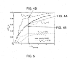
- FIG. 5 shows an illustration of the results of numerical simulations relating to the mixing of the tin concentration in the lower container half: temporal development of the volume-averaged Sn concentration in the lower container volume for various scenarios
- FIG. 7 shows solidification of an Al—Si alloy under the influence of a magnetic field (microstructure), wherein
- FIG. 8 shows a radial distribution of the surface fraction of primary crystals in Al-7 wt % Si samples (with seven Si weight fractions) that were solidified under the influence of a magnetic field with variation of the pulse duration T.
- FIGS. 1 , 1 a , 1 b show a schematic of an inventive device 1 for stirring a fluid, in the liquid state, in the form of a metallic melt 2 by using a rotating magnetic field which produces a Lorentz force F L in the horizontal plane, the device 1 comprising at least
- the pairs 31 , 32 , 33 of the induction coils are connected to a control/regulation unit 12 that passes on a rotary current I D to the pairs 31 , 32 , 33 of induction coils via a connected power supply unit 11 , the phase angle of the rotary current I D feeding the pairs 31 , 32 , 33 of the induction coils being displaced by 180° in regular time intervals in accordance with the prescribed period T PM for the mixing in the liquid state or T PE for the mixing from the beginning of the solidification, and a reversal of the direction of rotation of the magnetic field and of the Lorentz force F L driving the flow thereby being achieved, the control/regulation unit 12 being connected to the temperature sensor 10 , whose temperature data at the instant of the beginning of the solidification initiates the switchover of the period from T PM to T PE .
- the cylindrical container 13 is filled with the liquid, electrically conductive first melt 2 .
- the container 13 is located in a centrally symmetrical fashion inside the arrangement 3 of the induction coil pairs 31 , 32 , 33 , as is shown in FIG. 1 b .
- the induction coil pairs 31 , 32 , 33 are fed by a power supply unit 11 with a rotary current I D in the form of a three-phase alternating current, and produce a magnetic field that rotates about the axis of symmetry 14 of the container 13 and is horizontally aligned with the direction of rotation 15 (direction of the arrow).
- the time change in the magnetic field strength produces a Lorentz force F L with a dominating azimuthal component that sets the melt 2 in FIG.
- the power supply unit 11 of the induction coil pairs 31 , 32 , 33 is connected to the control/regulation unit 12 , which effects a displacement of the phases of the three-phase alternating current I D in prescribed time intervals.
- the phase displacement effects a displacement of the phases of the three-phase alternating current I D in prescribed time intervals.
- the direction of rotation 15 of the horizontally aligned magnetic field is reversed during the change in phase into the direction of rotation 16 , as shown in FIG. 1 b.
- the method can be used, for example to homogenize the temperature distribution in a single-component melt 2 , as shown in FIG. 2 a , or in order to bring about a concentration compensation in separated multicomponent melts 21 , 22 , as shown in FIG. 2 b , the melt 22 with the higher density before the beginning of mixing being located in the lower part of the container 13 and being covered by the lighter melt 21 .
- the mode of operation of the device 1 is explained in more detail in accordance with FIG. 1 and FIGS. 2 a , 2 b.
- the method for electromagnetic stirring is based on a periodic reversal of the direction of the Lorentz force F L driving the flow.
- the character of the flow is determined by a periodic change in the direction of rotation 15 - 16 , 16 - 15 of the magnetic field B 0 .
- the flow is braked and the melt 2 ; 21 , 22 is accelerated in the opposite direction.
- the Lorentz force F L varies in an axial direction with the associated force component and has a maximum in the central plane 17 of the container 13 .
- the melt 2 ; 21 , 22 in the surroundings of the central plane 17 is more strongly braked, and accelerated in the opposite direction 16 , than is the case in the vicinity of the bottom 4 of the container 13 and of the free surface 5 .
- the non-simultaneities in the reversal of direction 15 - 16 , 16 - 15 of the flow produce strong gradients in the rotational motion in an axial direction of the axis of symmetry 14 . As shown in FIG. 1 c , the occurrence of such gradients leads to an excitation of the meridional secondary flow 18 .
- a comparatively short period T P is advantageous, since relatively frequent changes in direction 15 - 16 , 16 - 15 reinforce the secondary flow 18 .
- the period T P becomes too short, the melt 2 ; 21 , 22 cannot be sufficiently accelerated, and both the primary rotational motion 19 and secondary flow 18 experience a loss of intensity.
- the period T P is a function of the magnetic field strength B 0 , size and shape of the volume and the material properties of the melt 2 ; 21 , 22 .
- the parameter t i.a. is the so-called initial adjustment time, and denotes the time scale of the formation of the double vortex that is typical of the meridional secondary flow 18 which formation occurs after an abrupt switching on of a rotating magnetic field in a melt 2 ; 21 , 22 that was previously in a state of rest.
- the initial adjustment time t i.a. is defined by the following equation
- the variables ⁇ , ⁇ , ⁇ and B 0 denoting the electrical conductivity and the density of the melt, the frequency and the amplitude of the magnetic field, while the constant C g describes the influence of the size and shape of the melt volume, and can assume numerical values of between three and five.
- the experimental results substantiate the existence of a specific period T P for which the intensity of the meridional secondary flow 18 reaches a maximum.
- the position of the maximum U zmax 2 varies with the magnetic field strength and corresponds to the respective initial adjustment time t i.a. .
- the invention can be used to intermix various melts 21 , 22 .
- half each of liquid lead 22 and liquid tin 21 can be located in the cylindrical container 13 .
- the lead 22 is much heavier and rests in the lower half of the container 13 before the beginning of mixing.
- the rotating magnetic field B 0 is switched on, its direction of rotation being reversed in regular time intervals.
- the results of numerical simulations are contained in FIG. 4 and FIGS. 4 a , 4 b , 4 c for a magnetic field of 1 mT with regard to the concentration distribution of lead (black) 22 and tin (white) 21 in an r-z half plane after a specific time of 20 s, in which case in
- FIG. 4 c , T P 2 t i.a.
- the device 1 illustrated in FIG. 2 , of the cylindrical container 13 , filled with an electrically conductive melt 2 , in the arrangement 3 of induction coil pairs 31 , 32 , 33 can be supplemented by a cooling device 23 for the solidification of metallic melts 2 .
- the cooling device 23 includes a metal block 6 in whose interior cooling channels 7 are present.
- the container 13 stands on the metal block 6 .
- a coolant flows through the cooling channels 7 located in the interior of the metal block 6 .
- the heat is withdrawn downward from the melt 2 by means of the cooling device 23 .
- a thermal insulation 8 of the container 13 prevents heat losses in a radial direction.
- At least one temperature sensor 10 is fitted on the bottom 4 and the side walls 20 of the container 13 , for example in the form of a thermocouple.
- the temperature measurements enable the beginning and the course of the state of solidification to be monitored, and enable an immediate adaptation of the magnetic field parameters (for example B 0 and T P ) to the individual stages of the solidification process by the power supply unit 11 controlled by means of the control/regulation unit 12 .
- the periodic reversal of the direction of the Lorentz force F L driving the flow is continued for the purpose of continuing to stir the solidifying melt 2 .
- the period T PE is set in such a way that the melt 2 is effectively mixed and the direction of the meridional secondary flow 18 is subjected to a constant change in direction in the surroundings of the solidification front.
- Al—Si alloys 21 , 22 can be directionally solidified under temperature control in the inventive device 1 in accordance with FIGS. 1 , 2 b .
- the structural properties obtained are explained in more detail with the aid of FIGS. 6 a , 6 b , 6 c , 7 a , 7 b and 8 with reference to the formation of columnar dendrites, grain refinement and separation:
- FIG. 6 shows the macrostructure in longitudinal section of cylindrical blocks of an Al-7 wt % Si alloy, for example given a diameter of 50 mm and a height of 60 mm, that was directionally solidified under the influence of a rotating magnetic field at a field strength B 0 of 6.5 mT.
- the magnetic field was switched on with a time delay of 30 s after the beginning of the solidification at the container bottom.
- a coarse columnar structure grows parallel to the axis of symmetry of the container in the period up to the beginning of the electromagnetically driven flow. As shown in FIG.
- FIG. 8 is a radial distribution of the surface fraction of primary crystals in Al-7 wt % Si samples (with seven Si weight fractions) that were solidified under the influence of a magnetic field with variation of the pulse duration T.
- FIGS. 6 to 8 show that a direct transition to equiaxial grain growth can be achieved in the case of electromagnetic stirring with change in direction of the magnetic field and switching on of the magnetic field.
- the periodic change in the direction of rotation of the magnetic field leads in each case to a reduction in separation, it even being possible to avoid separation almost completely given suitable selection of the pulse duration T P , as shown in FIG. 7 b .
- the application of the invention can be used for mixing metal melts 2 ; 21 , 22 for continuous casting, for the directional solidification of mixed metallic alloys, and for directional solidification of semiconductor melts, inter alia.
Landscapes
- Engineering & Computer Science (AREA)
- Mechanical Engineering (AREA)
- Chemical & Material Sciences (AREA)
- Materials Engineering (AREA)
- Metallurgy (AREA)
- Organic Chemistry (AREA)
- General Engineering & Computer Science (AREA)
- Chemical Kinetics & Catalysis (AREA)
- Continuous Casting (AREA)
- Mixers With Rotating Receptacles And Mixers With Vibration Mechanisms (AREA)
- Waste-Gas Treatment And Other Accessory Devices For Furnaces (AREA)
Applications Claiming Priority (3)
| Application Number | Priority Date | Filing Date | Title |
|---|---|---|---|
| DE200710037340 DE102007037340B4 (de) | 2007-08-03 | 2007-08-03 | Verfahren und Einrichtung zum elektromagnetischen Rühren von elektrisch leitenden Flüssigkeiten |
| DE102007037340.8 | 2007-08-03 | ||
| PCT/DE2008/001260 WO2009018809A1 (de) | 2007-08-03 | 2008-08-01 | Verfahren und einrichtung zum elektromagnetischen rühren von elektrisch leitenden flüssigkeiten |
Publications (1)
| Publication Number | Publication Date |
|---|---|
| US20110297239A1 true US20110297239A1 (en) | 2011-12-08 |
Family
ID=40120237
Family Applications (2)
| Application Number | Title | Priority Date | Filing Date |
|---|---|---|---|
| US12/672,036 Abandoned US20110297239A1 (en) | 2007-08-03 | 2008-08-01 | Method and device for the electromagnetic stirring of electrically conductive fluids |
| US14/094,350 Expired - Fee Related US8944142B2 (en) | 2007-08-03 | 2013-12-02 | Method and device for the electromagnetic stirring of electrically conductive fluids |
Family Applications After (1)
| Application Number | Title | Priority Date | Filing Date |
|---|---|---|---|
| US14/094,350 Expired - Fee Related US8944142B2 (en) | 2007-08-03 | 2013-12-02 | Method and device for the electromagnetic stirring of electrically conductive fluids |
Country Status (5)
| Country | Link |
|---|---|
| US (2) | US20110297239A1 (enExample) |
| EP (1) | EP2190612B1 (enExample) |
| JP (1) | JP5124863B2 (enExample) |
| DE (1) | DE102007037340B4 (enExample) |
| WO (1) | WO2009018809A1 (enExample) |
Cited By (15)
| Publication number | Priority date | Publication date | Assignee | Title |
|---|---|---|---|---|
| US20120085448A1 (en) * | 2010-10-06 | 2012-04-12 | Searete Llc | Electromagnetic flow regulator, system, and methods for regulating flow of an electrically conductive fluid |
| US20120085423A1 (en) * | 2010-10-06 | 2012-04-12 | Searete Llc, A Limited Liablity Corporation Of The State Of Delaware | Electromagnetic flow regulator, system, and methods for regulating flow of an electrically conductive fluid |
| CN102980415A (zh) * | 2012-11-20 | 2013-03-20 | 中国科学院研究生院 | 基于通电线圈螺旋磁场驱动金属熔体周期性流动的方法 |
| US8453330B2 (en) | 2010-10-06 | 2013-06-04 | The Invention Science Fund I | Electromagnet flow regulator, system, and methods for regulating flow of an electrically conductive fluid |
| US8781056B2 (en) | 2010-10-06 | 2014-07-15 | TerraPower, LLC. | Electromagnetic flow regulator, system, and methods for regulating flow of an electrically conductive fluid |
| US9008257B2 (en) | 2010-10-06 | 2015-04-14 | Terrapower, Llc | Electromagnetic flow regulator, system and methods for regulating flow of an electrically conductive fluid |
| CN106029256A (zh) * | 2014-02-25 | 2016-10-12 | 新日铁住金株式会社 | 钢的连续铸造方法 |
| CN106922199A (zh) * | 2014-07-28 | 2017-07-04 | 科罗拉多州立大学董事会,公司实体 | 用于控制流动行为的声子材料 |
| CN109261939A (zh) * | 2017-07-17 | 2019-01-25 | 中国科学院大学 | 一种利用液态金属进行增材制造的装置及方法 |
| CN109482844A (zh) * | 2019-01-02 | 2019-03-19 | 江苏大学 | 复杂精密铸件细晶铸造装置及方法 |
| US10281216B2 (en) | 2014-03-27 | 2019-05-07 | Kenzo Takahashi | Molten metal stirring device and molten metal transfer device |
| CN114559002A (zh) * | 2022-04-06 | 2022-05-31 | 上海大学 | 一种旋转磁场二次流的控制方法 |
| US20220252091A1 (en) * | 2021-02-05 | 2022-08-11 | Arizona Board of Regents on behalf Arizona State Univernity | Robotic devices using magnetic fields for three-dimensional control of fluids |
| CN115647335A (zh) * | 2022-10-26 | 2023-01-31 | 山东大学 | 一种多物理场耦合作用的金属凝固装置及方法 |
| CN115889734A (zh) * | 2022-10-27 | 2023-04-04 | 中国航发北京航空材料研究院 | 一种可实时监控温度梯度的加热器底座装置 |
Families Citing this family (11)
| Publication number | Priority date | Publication date | Assignee | Title |
|---|---|---|---|---|
| DE102013009773B4 (de) * | 2013-06-05 | 2016-02-11 | Technische Universität Dresden | Vorrichtung sowie Verfahren zur Steigerung der Anbindungseffizienz von zur Bindung befähigten Zielstrukturen |
| AT515244A2 (de) * | 2013-12-30 | 2015-07-15 | Inteco Special Melting Technologies Gmbh | Verfahren zur Herstellung von langen Gussblöcken großen Querschnitts |
| JP6234841B2 (ja) * | 2014-02-24 | 2017-11-22 | 株式会社神戸製鋼所 | チタンまたはチタン合金からなる鋳塊の連続鋳造装置 |
| CN104826533B (zh) * | 2015-05-11 | 2016-11-09 | 兰州大学 | 可组合式环形立体磁力搅拌器 |
| US10898949B2 (en) | 2017-05-05 | 2021-01-26 | Glassy Metals Llc | Techniques and apparatus for electromagnetically stirring a melt material |
| DE102018105700A1 (de) | 2018-03-13 | 2019-09-19 | Technische Universität Ilmenau | Vorrichtung und Verfahren zum nicht-invasiven Rühren eines elektrisch leitfähigen Fluids |
| KR102818103B1 (ko) | 2020-08-03 | 2025-06-11 | 삼성전자주식회사 | 열 전달 물질 및 그 제조 방법과 이를 포함하는 반도체 패키지 |
| EP4234120A4 (en) * | 2020-12-25 | 2024-04-03 | JFE Steel Corporation | CONTINUOUS CASTING PROCESS FOR STEEL |
| CN115645968B (zh) * | 2022-10-11 | 2023-06-30 | 浙江佳人新材料有限公司 | 一种dmt捕集回收工艺 |
| CN116329530B (zh) * | 2023-05-12 | 2023-08-04 | 山西昌鸿电力器材有限公司 | 一种金具智能化铸造工艺 |
| CN118028620B (zh) * | 2024-02-20 | 2024-07-09 | 南通泰德电子材料科技有限公司 | 一种电磁搅拌下的定向凝固提取超高纯铝方法 |
Citations (5)
| Publication number | Priority date | Publication date | Assignee | Title |
|---|---|---|---|---|
| US4969501A (en) * | 1989-11-09 | 1990-11-13 | Pcc Airfoils, Inc. | Method and apparatus for use during casting |
| US5769147A (en) * | 1994-12-06 | 1998-06-23 | Showa Denko Kabushikikaisha | Method for producing metallic ingot for plastic working |
| US6402367B1 (en) * | 2000-06-01 | 2002-06-11 | Aemp Corporation | Method and apparatus for magnetically stirring a thixotropic metal slurry |
| US20050061474A1 (en) * | 2003-09-18 | 2005-03-24 | Gelorme Jeffrey D. | Method and apparatus for chip-cooling |
| US20100163207A1 (en) * | 2007-08-03 | 2010-07-01 | Forschungszentrum Dresden-Rossendorf E. V. | Method and device for the electromagnetic stirring of electrically conductive fluids |
Family Cites Families (8)
| Publication number | Priority date | Publication date | Assignee | Title |
|---|---|---|---|---|
| DE1962341B2 (de) | 1969-12-12 | 1971-06-24 | Aeg Elotherm Gmbh | Anordnung einer mehrphasigen elektromagnetischen wicklung am strangfuehrungsgeruest einer stranggiessanlage |
| JPS5252895Y2 (enExample) * | 1973-04-18 | 1977-12-01 | ||
| DE3730300A1 (de) | 1987-09-10 | 1989-03-23 | Aeg Elotherm Gmbh | Verfahren und vorrichtung zum elektromagnetischen ruehren von metallschmelzen in einer stranggiesskokille |
| JPH09182941A (ja) * | 1995-12-28 | 1997-07-15 | Nippon Steel Corp | 連続鋳造鋳型内溶鋼の電磁撹拌方法 |
| JP3372958B2 (ja) * | 1997-12-08 | 2003-02-04 | 新日本製鐵株式会社 | 溶融金属の鋳造方法およびその装置並びに鋳片 |
| SE519840C2 (sv) | 2000-06-27 | 2003-04-15 | Abb Ab | Förfarande och anordning för kontinuerlig gjutning av metaller |
| JP2005066613A (ja) * | 2003-08-21 | 2005-03-17 | Yaskawa Electric Corp | 電磁攪拌装置 |
| DE102004017443B3 (de) | 2004-04-02 | 2005-04-21 | Technische Universität Dresden | Verfahren und Vorrichtung zum Rühren von elektrisch leitenden Flüssigkeiten in Behältern |
-
2007
- 2007-08-03 DE DE200710037340 patent/DE102007037340B4/de not_active Expired - Fee Related
-
2008
- 2008-08-01 JP JP2010518494A patent/JP5124863B2/ja not_active Expired - Fee Related
- 2008-08-01 EP EP08801098.8A patent/EP2190612B1/de not_active Not-in-force
- 2008-08-01 WO PCT/DE2008/001260 patent/WO2009018809A1/de not_active Ceased
- 2008-08-01 US US12/672,036 patent/US20110297239A1/en not_active Abandoned
-
2013
- 2013-12-02 US US14/094,350 patent/US8944142B2/en not_active Expired - Fee Related
Patent Citations (5)
| Publication number | Priority date | Publication date | Assignee | Title |
|---|---|---|---|---|
| US4969501A (en) * | 1989-11-09 | 1990-11-13 | Pcc Airfoils, Inc. | Method and apparatus for use during casting |
| US5769147A (en) * | 1994-12-06 | 1998-06-23 | Showa Denko Kabushikikaisha | Method for producing metallic ingot for plastic working |
| US6402367B1 (en) * | 2000-06-01 | 2002-06-11 | Aemp Corporation | Method and apparatus for magnetically stirring a thixotropic metal slurry |
| US20050061474A1 (en) * | 2003-09-18 | 2005-03-24 | Gelorme Jeffrey D. | Method and apparatus for chip-cooling |
| US20100163207A1 (en) * | 2007-08-03 | 2010-07-01 | Forschungszentrum Dresden-Rossendorf E. V. | Method and device for the electromagnetic stirring of electrically conductive fluids |
Non-Patent Citations (1)
| Title |
|---|
| http://en.wikipedia.org/wiki/Three-phase_electric_power, date unknown * |
Cited By (21)
| Publication number | Priority date | Publication date | Assignee | Title |
|---|---|---|---|---|
| US20120085448A1 (en) * | 2010-10-06 | 2012-04-12 | Searete Llc | Electromagnetic flow regulator, system, and methods for regulating flow of an electrically conductive fluid |
| US20120085423A1 (en) * | 2010-10-06 | 2012-04-12 | Searete Llc, A Limited Liablity Corporation Of The State Of Delaware | Electromagnetic flow regulator, system, and methods for regulating flow of an electrically conductive fluid |
| US20120138179A1 (en) * | 2010-10-06 | 2012-06-07 | Searete Llc, A Limited Liability Corporation Of The State Of Delaware | Electromagnetic flow regulator, system, and methods for regulating flow of an electrically conductive fluid |
| US8397760B2 (en) * | 2010-10-06 | 2013-03-19 | The Invention Science Fund I, Llc | Electromagnetic flow regulator, system, and methods for regulating flow of an electrically conductive fluid |
| US8430129B2 (en) * | 2010-10-06 | 2013-04-30 | The Invention Science Fund I, Llc | Electromagnetic flow regulator, system, and methods for regulating flow of an electrically conductive fluid |
| US8453330B2 (en) | 2010-10-06 | 2013-06-04 | The Invention Science Fund I | Electromagnet flow regulator, system, and methods for regulating flow of an electrically conductive fluid |
| US8584692B2 (en) * | 2010-10-06 | 2013-11-19 | The Invention Science Fund I, Llc | Electromagnetic flow regulator, system, and methods for regulating flow of an electrically conductive fluid |
| US8781056B2 (en) | 2010-10-06 | 2014-07-15 | TerraPower, LLC. | Electromagnetic flow regulator, system, and methods for regulating flow of an electrically conductive fluid |
| US9008257B2 (en) | 2010-10-06 | 2015-04-14 | Terrapower, Llc | Electromagnetic flow regulator, system and methods for regulating flow of an electrically conductive fluid |
| CN102980415A (zh) * | 2012-11-20 | 2013-03-20 | 中国科学院研究生院 | 基于通电线圈螺旋磁场驱动金属熔体周期性流动的方法 |
| CN106029256A (zh) * | 2014-02-25 | 2016-10-12 | 新日铁住金株式会社 | 钢的连续铸造方法 |
| CN106029256B (zh) * | 2014-02-25 | 2017-10-27 | 新日铁住金株式会社 | 钢的连续铸造方法 |
| US10281216B2 (en) | 2014-03-27 | 2019-05-07 | Kenzo Takahashi | Molten metal stirring device and molten metal transfer device |
| CN106922199A (zh) * | 2014-07-28 | 2017-07-04 | 科罗拉多州立大学董事会,公司实体 | 用于控制流动行为的声子材料 |
| CN109261939A (zh) * | 2017-07-17 | 2019-01-25 | 中国科学院大学 | 一种利用液态金属进行增材制造的装置及方法 |
| CN109482844A (zh) * | 2019-01-02 | 2019-03-19 | 江苏大学 | 复杂精密铸件细晶铸造装置及方法 |
| US20220252091A1 (en) * | 2021-02-05 | 2022-08-11 | Arizona Board of Regents on behalf Arizona State Univernity | Robotic devices using magnetic fields for three-dimensional control of fluids |
| US12173734B2 (en) * | 2021-02-05 | 2024-12-24 | Arizona Board Of Regents On Behalf Of Arizona State University | Robotic devices using magnetic fields for three-dimensional control of fluids |
| CN114559002A (zh) * | 2022-04-06 | 2022-05-31 | 上海大学 | 一种旋转磁场二次流的控制方法 |
| CN115647335A (zh) * | 2022-10-26 | 2023-01-31 | 山东大学 | 一种多物理场耦合作用的金属凝固装置及方法 |
| CN115889734A (zh) * | 2022-10-27 | 2023-04-04 | 中国航发北京航空材料研究院 | 一种可实时监控温度梯度的加热器底座装置 |
Also Published As
| Publication number | Publication date |
|---|---|
| DE102007037340B4 (de) | 2010-02-25 |
| US8944142B2 (en) | 2015-02-03 |
| EP2190612B1 (de) | 2017-12-20 |
| EP2190612A1 (de) | 2010-06-02 |
| WO2009018809A1 (de) | 2009-02-12 |
| DE102007037340A1 (de) | 2009-02-19 |
| JP2010535105A (ja) | 2010-11-18 |
| US20140290433A1 (en) | 2014-10-02 |
| JP5124863B2 (ja) | 2013-01-23 |
Similar Documents
| Publication | Publication Date | Title |
|---|---|---|
| US8944142B2 (en) | Method and device for the electromagnetic stirring of electrically conductive fluids | |
| JP2010535105A5 (enExample) | ||
| JP7242754B2 (ja) | 混合エダクタノズル及び流動制御デバイス | |
| US20100163207A1 (en) | Method and device for the electromagnetic stirring of electrically conductive fluids | |
| JP2010535106A5 (enExample) | ||
| US2963758A (en) | Production of fine grained metal castings | |
| Denisov et al. | THE EFFECT OF TRAVELING AND ROTATING MAGNETIC FIELDS ON THE STRUCTURE OF ALUMINUM ALLOY DURING ITS CRYSTALLIZATION IN A CYLINDRICAL CRUCIBLE. | |
| US7449143B2 (en) | Systems and methods of electromagnetic influence on electroconducting continuum | |
| EP2682201A1 (en) | Method and apparatus for the continuous casting of aluminium alloys | |
| Cheng et al. | Effect of Modulated Helical Magnetic Field on Solidifying Segregation of Sn–3.5 Wt Pct Pb Alloy in a Directional Solidification | |
| Garnier | The Clifford Paterson Lecture, 1992 Magentohydrodynamics in material processing | |
| Turchin et al. | Effects of solidification range on the structure of aluminium alloys obtained under conditions of constant melt flow | |
| UA78923C2 (en) | Method of electromagnetic mixing of liquid metal by the system of rotating magnetic fields |
Legal Events
| Date | Code | Title | Description |
|---|---|---|---|
| AS | Assignment |
Owner name: HELMHOLTZ-ZENTRUM DRESDEN-ROSSENDORF E.V., GERMANY Free format text: ASSIGNMENT OF ASSIGNORS INTEREST;ASSIGNORS:NIKRITYUK, PETR;ECKERT, SVEN;RAEBIGER, DIRK;AND OTHERS;SIGNING DATES FROM 20131212 TO 20131222;REEL/FRAME:031948/0227 |
|
| STCB | Information on status: application discontinuation |
Free format text: ABANDONED -- FAILURE TO RESPOND TO AN OFFICE ACTION |