US20100131215A1 - Insulation monitoring system & insulation detecting method for electric power supply system - Google Patents
Insulation monitoring system & insulation detecting method for electric power supply system Download PDFInfo
- Publication number
- US20100131215A1 US20100131215A1 US12/377,110 US37711007A US2010131215A1 US 20100131215 A1 US20100131215 A1 US 20100131215A1 US 37711007 A US37711007 A US 37711007A US 2010131215 A1 US2010131215 A1 US 2010131215A1
- Authority
- US
- United States
- Prior art keywords
- phase
- component
- leakage current
- voltage
- zero
- Prior art date
- Legal status (The legal status is an assumption and is not a legal conclusion. Google has not performed a legal analysis and makes no representation as to the accuracy of the status listed.)
- Abandoned
Links
Images

Classifications
-
- G—PHYSICS
- G01—MEASURING; TESTING
- G01R—MEASURING ELECTRIC VARIABLES; MEASURING MAGNETIC VARIABLES
- G01R31/00—Arrangements for testing electric properties; Arrangements for locating electric faults; Arrangements for electrical testing characterised by what is being tested not provided for elsewhere
- G01R31/50—Testing of electric apparatus, lines, cables or components for short-circuits, continuity, leakage current or incorrect line connections
- G01R31/52—Testing for short-circuits, leakage current or ground faults
-
- G—PHYSICS
- G01—MEASURING; TESTING
- G01R—MEASURING ELECTRIC VARIABLES; MEASURING MAGNETIC VARIABLES
- G01R27/00—Arrangements for measuring resistance, reactance, impedance, or electric characteristics derived therefrom
- G01R27/02—Measuring real or complex resistance, reactance, impedance, or other two-pole characteristics derived therefrom, e.g. time constant
- G01R27/16—Measuring impedance of element or network through which a current is passing from another source, e.g. cable, power line
- G01R27/18—Measuring resistance to earth, i.e. line to ground
Definitions
- the present invention relates to an insulation detecting apparatus and an insulation detecting method for a power line. More specifically, the present invention relates to an insulation detecting apparatus and method, in which an insulation state can be correctly detected by calculating insulation resistance and electrostatic capacitance of a power line including a load even when electrostatic capacitance between a three-phase power line including the load and the ground is in an unbalanced state, as well as in a balanced state.
- active component leakage current (or insulation resistance) between a power line including a load and the ground that is directly related to an insulation state or reactive component leakage current (or electrostatic capacitance) that is not directly related to the insulation state, but generated by ever-existing electrostatic capacitance, is calculated, displayed, and outputted together with an alarm.
- the insulation detecting apparatus can be remotely controlled through a communication unit.
- a conventional method of monitoring the insulation state of a power line including a load uses a method of detecting a zero-phase leakage current to component flowing through a ground line 5 or detecting zero-phase leakage current Io flowing between the power line 3 with a load and the ground as shown in FIG. 1 .
- the power line means a power distribution line including a load, a high voltage distribution line, and a low voltage distribution line
- a zero-phase current transformer means a current transformer that can detect a zero-phase leakage current component.
- a voltage detection line means a component that can detect a voltage component by directly connecting to a wire or detect a voltage component of the power line using a non-contact method.
- alternating voltage is supplied to a load 4 through a transformer 1 for transforming voltage, a switch 2 , and a power line 3 .
- the secondary side of the transformer 1 is a Y-connection, and the neutral point of the Y-connection is connected to the ground 6 through a ground line 5 .
- Active component leakage current Ir and reactive component leakage current Ic flow between the power line 3 and the ground.
- the active component leakage current Ir is generated by an insulation resistance 9 component directly related to an insulation state
- the reactive component leakage current Ic is generated by an electrostatic capacitance 8 component that is not directly related to the insulation state, but generated if the power line 3 is long or a noise filter is installed at the input terminal of the load 4 .
- Zero-phase leakage current Io Ir+Ic, which is a vector sum of the two components, flows through the ground line 5 of the transformer.
- a method of detecting an insulation state only with the zero-phase leakage current Io which is leakage current detected at the middle of the ground line 5 connected to the secondary side of the transformer 1 or at the secondary side of the zero-phase current transformer 10 that flows three phases of the power line 3 all together.
- Electrical devices using the method of detecting zero-phase leakage current to described above include an electric leakage breaker, electric leakage alarm, electric leakage detector, ground fault detector, and the like.
- the zero-phase leakage current to is detected high even at a power line where insulation resistance 9 is small, i.e., where the insulation state is favorable, and thus the insulation state is displayed as unfavorable, or although constant active component leakage current Ir generated by the insulation resistance 9 component flows, since the active component leakage current Ir is small due to a magnetic field characteristic of the zero-phase current transformer 10 , the detected zero-phase leakage current Io varies depending on the magnitude of the reactive component leakage current Ic generated by the electrostatic capacitance 8 component, and therefore, there is a problem in that the insulation state cannot be correctly detected.
- an insulation detecting apparatus and an insulation detecting method that can correctly monitor an insulation state between the power line 3 including the load 4 and the ground even when electrostatic capacitance existing between the three-phase power line and the ground is in an unbalanced state, as well as in a balanced state.
- the present invention has been made in order to solve the above problems, and it is an object of the invention to provide an insulation detecting apparatus, in which an insulation state of a power line including a load can be correctly detected even when electrostatic capacitance between the three-phase power line including a load and the ground is in an unbalanced state, as well as in a balanced state.
- Another object of the invention is to provide an insulation detecting apparatus, in which active component leakage current (or insulation resistance) between a power line and the ground that is directly related to an insulation state or reactive component leakage current (or electrostatic capacitance) that is not directly related to the insulation state, but generated by ever-existing electrostatic capacitance, can be calculated, displayed, and outputted together with an alarm, and which can be remotely controlled through a communication unit.
- active component leakage current or insulation resistance
- reactive component leakage current or electrostatic capacitance
- a further object of the invention is to provide an insulation detecting method, in which an insulation state of a power line including a load can be correctly detected even when electrostatic capacitance between the three-phase power line including a load and the ground is in an unbalanced state, as well as in a balanced state.
- an insulation detecting apparatus for detecting an insulation state, comprising: a voltage detecting means for transforming a voltage component of each of three phases of the power line including a load into a voltage component of a certain magnitude and collectively extracting voltage of each of the three phases; a zero-phase current transformer for detecting zero-phase leakage current flowing between the power line and ground; a leakage current detecting means for converting a leakage current component detected by the zero-phase current transformer into a voltage component and extracting a frequency component lower than a certain frequency or a frequency component of a commercial frequency band; a phase comparing means for detecting a phase difference between an output value of each of the three phases of the voltage detecting means and an output value of the leakage current detecting means; an analog-to-digital conversion unit for converting an analog component of the output value of the leakage current detecting means into a digital component; an operation controller for reading, outputting, operating, and controlling a
- the leakage current detecting means comprises: the zero-phase current transformer for detecting leakage current between the power line and the ground; a current-to-voltage conversion unit for converting a leakage current component detected by the zero-phase current transformer into a voltage component; an amplification unit for amplifying the leakage current component converted by the current-to-voltage conversion unit; and a current filter unit for extracting a frequency component lower than a certain frequency or a frequency component of a commercial frequency band from the leakage current component amplified by the amplification unit 42 .
- the voltage detecting means comprises: a voltage detecting unit for transforming a voltage component of each of three phases of the power line including a load into a voltage component of a certain magnitude and collectively detecting three phase voltage; and a voltage filter unit for extracting a frequency component lower than a certain frequency or a frequency component of a commercial frequency band from the voltage component transformed by the voltage detecting unit.
- the phase comparing means comprises: a voltage component waveform shaping unit for shaping a waveform of the voltage component outputted from the voltage detecting means; a current component waveform shaping unit for shaping a waveform of the leakage current component outputted from the leakage current detecting means; and a phase difference detecting unit for detecting a phase difference of an output of the current component waveform shaping unit from an output of the voltage component waveform shaping unit.
- the voltage detecting unit is configured with any one of a resistor, a condenser, and a transformer having the same impedance between each phase of the three-phase power line and the ground.
- the input-output unit comprises an input unit for inputting a variety of data, a display unit for displaying and outputting a variety of data, and a memory unit for storing a variety of data.
- an insulation detecting apparatus for detecting an insulation state, comprising: a voltage detecting means for transforming a voltage component of the power line including a load into a voltage component of a certain magnitude and sequentially extracting a voltage component of each of the three phases, one phase at a time; a zero-phase current transformer for detecting zero-phase leakage current flowing between the power line and ground; a leakage current detecting means for converting a leakage current component detected by the zero-phase current transformer into a voltage component and extracting a frequency component lower than a certain frequency or a frequency component of a commercial frequency band; a phase comparing means for detecting a phase difference between an output value of each of the three phases of the voltage detecting means and an output value of the leakage current detecting means; an analog-to-digital conversion unit for converting an analog component of the output value of the leakage current detecting means into a digital component; an operation controller for reading, outputting, operating, and controlling a variety of data; and an
- the voltage detecting means comprises: a voltage detecting unit for detecting a voltage component of each of three phases of the power line including a load and transforming the voltage component into a voltage component of a certain magnitude; a phase selection unit for selecting a voltage component of only one phase of three phases from the voltage component transformed by the voltage detecting unit; and a voltage filter unit for extracting a frequency component lower than a certain frequency or a frequency component of a commercial frequency band from the voltage component of the phase selected by the phase selection unit 32 .
- the leakage current detecting means comprises: the zero-phase current transformer for detecting leakage current between the power line and the ground; a current-to-voltage conversion unit for converting a leakage current component detected by the zero-phase current transformer 10 into a voltage component; a current filter unit for extracting a frequency component lower than a certain frequency or a frequency component of a commercial frequency band from the leakage current component converted by the current-to-voltage conversion unit; and an amplification unit for amplifying the leakage current component extracted by the current filter unit.
- the insulation detecting apparatus of the present invention further comprises a communication unit for remotely monitoring the insulation detecting apparatus from outside.
- insulation detecting method for a power line which can detect an insulation state of the power line even when electrostatic capacitance between the power line and ground is in an unbalanced state, as well as in a balanced state, comprising the steps of: allowing the leakage current detecting means to detect a leakage current component Io 1 from a zero-phase leakage current component detected at a secondary side of a zero-phase current transformer, allowing a voltage detecting means to detect a voltage component Vf by extracting only a frequency component, and detecting a phase difference of the leakage current component Io 1 from the voltage component Vf of each of the three phases outputted from the voltage detecting means; calculating an in-phase component and a 90° phase-shifted component of the leakage current component Io 1 of each phase; calculating a 90° phase-shifted zero value of each phase and/or an in-phase component zero value of each phase; verifying data on active component leakage current or reactive component leakage current of each phase calculated and stored in the
- an active component leakage current generated by insulation resistors or reactive component leakage current generated by electrostatic capacitance is detected by calculating a reactive component zero leakage current, with which the reactive component leakage current generated by the electrostatic capacitance between the power line and the ground becomes zero in each of three phases.
- an active component leakage current generated by insulation resistors or reactive component leakage current generated by electrostatic capacitance is detected by calculating an active component zero leakage current, with which the active component leakage current generated by the insulation resistors between the power line and the ground becomes zero in each of three phases.
- an active component leakage current generated by insulation resistors or reactive component leakage current generated by electrostatic capacitance is detected by calculating an active component zero leakage current and a reactive component zero leakage current, with which the active component leakage current generated by the insulation resistors and the reactive component leakage current generated by the electrostatic capacitance between the power line and the ground become zero in each of three phases.
- active leakage current generated by insulation resistors or insulation resistance which is an insulation state of a power line including a load
- insulation resistors or insulation resistance which is an insulation state of a power line including a load
- an alarm state is displayed on a display unit by comparing current leakage with an alarm level additionally inputted through an input unit or stored in a memory unit, or a variety of data or alarm states detected at a remote site can be remotely monitored through a remote control apparatus installed in the remote site and a communication unit having a communication and control function.
- FIG. 1 shows a connection diagram describing a conventional method of monitoring leakage current.
- FIG. 2 shows a connection diagram of an insulation detecting apparatus according to a first embodiment of the present invention.
- FIG. 3 shows a connection diagram of an insulation detecting apparatus according to a second embodiment of the present invention.
- FIG. 4 shows a connection diagram of an insulation detecting apparatus according to a third embodiment of the present invention.
- FIG. 5 shows a connection diagram of an insulation detecting apparatus according to a fourth embodiment of the present invention.
- FIG. 6 shows a connection diagram of an insulation detecting apparatus according to a fifth embodiment of the present invention.
- FIG. 7 shows a connection diagram of an insulation detecting apparatus according to a sixth embodiment of the present invention.
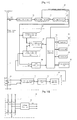
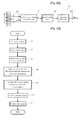
- FIG. 8 shows a block diagram of the insulation detecting apparatus used in FIGS. 2 to 7 according to a first embodiment of the insulation detecting apparatus.
- FIG. 9 shows a detailed circuit diagram of the insulation detecting apparatus used in FIG. 8 .
- FIG. 10 shows a block diagram of the insulation detecting apparatus used in FIGS. 2 to 7 according to a second embodiment of the insulation detecting apparatus.
- FIG. 11 shows a detailed circuit diagram of the insulation detecting apparatus used in FIG. 10 .
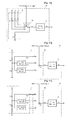
- FIG. 12 shows a detailed circuit diagram of the voltage detecting means used in FIGS. 8 and 9 according to a first embodiment of the voltage detecting means.
- FIG. 13 shows a detailed circuit diagram of the voltage detecting means used in FIGS. 8 and 9 according to a second embodiment of the voltage detecting means.
- FIG. 14 shows a detailed circuit diagram of the voltage detecting means used in FIGS. 10 and 11 according to a first embodiment of the voltage detecting means.
- FIG. 15 shows a detailed circuit diagram of the voltage detecting means used in FIGS. 10 and 11 according to a second embodiment of the voltage detecting means.
- FIG. 16 shows a detailed circuit diagram of the voltage detecting means used in FIGS. 10 and 11 according to a third embodiment of the voltage detecting means.
- FIG. 17 shows a detailed circuit diagram of the voltage detecting means used in FIGS. 10 and 11 according to a fourth embodiment of the voltage detecting means.
- FIG. 18 shows a detailed circuit diagram of the voltage detecting means used in FIGS. 10 and 11 according to a fifth embodiment of the voltage detecting means.
- FIG. 19 shows a detailed circuit diagram of the voltage detecting means used in FIGS. 10 and 11 according to a sixth embodiment of the voltage detecting means.
- FIG. 20 shows a detailed circuit diagram of the voltage detecting means used in FIGS. 10 and 11 according to a seventh embodiment of the voltage detecting means.
- FIG. 21 shows a detailed circuit diagram of the voltage detecting means used in FIGS. 10 and 11 according to an eighth embodiment of the voltage detecting means.
- FIG. 22 shows a detailed circuit diagram of the leakage current detecting means used in FIGS. 8 to 11 according to another embodiment of the leakage current detecting means.
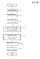
- FIG. 23 is a flowchart illustrating an insulation detecting method according to a first embodiment of the insulation detecting apparatus used in FIGS. 8 to 11 .
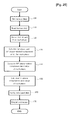
- FIG. 24 is a flowchart illustrating an insulation detecting method according to a second embodiment of the insulation detecting apparatus used in FIGS. 8 to 11 .
- FIG. 25 is a flowchart illustrating an insulation detecting method according to a third embodiment of the insulation detecting apparatus used in FIGS. 8 to 11 .
- FIG. 2 shows a connection diagram of an insulation detecting apparatus according to a first embodiment of the present invention
- FIG. 3 shows a connection diagram of an insulation detecting apparatus according to a second embodiment of the present invention
- FIG. 4 shows a connection diagram of an insulation detecting apparatus according to a third embodiment of the present invention
- FIG. 5 shows a connection diagram of an insulation detecting apparatus according to a fourth embodiment of the present invention
- FIG. 6 shows a connection diagram of an insulation detecting apparatus according to a fifth embodiment of the present invention
- FIG. 7 shows a connection diagram of an insulation detecting apparatus according to a sixth embodiment of the present invention.
- FIG. 8 shows a block diagram of the insulation detecting apparatus used in FIGS. 2 to 7 according to a first embodiment of the insulation detecting apparatus
- FIG. 9 shows a detailed circuit diagram of the insulation detecting apparatus used in FIG. 8
- FIG. 10 shows a block diagram of the insulation detecting apparatus used in FIGS. 2 to 7 according to a second embodiment of the insulation detecting apparatus
- FIG. 11 shows a detailed circuit diagram of the insulation detecting apparatus used in FIG. 10 .
- FIG. 12 shows a detailed circuit diagram of the voltage detecting means used in FIGS. 8 and 9 according to a first embodiment of the voltage detecting means
- FIG. 13 shows a detailed circuit diagram of the voltage detecting means used in FIGS. 8 and 9 according to a second embodiment of the voltage detecting means
- FIG. 14 shows a detailed circuit diagram of the voltage detecting means used in FIGS. 10 and 11 according to a first embodiment of the voltage detecting means
- FIG. 15 shows a detailed circuit diagram of the voltage detecting means used in FIGS. 10 and 11 according to a second embodiment of the voltage detecting means
- FIG. 16 shows a detailed circuit diagram of the voltage detecting means used in FIGS. 10 and 11 according to a third embodiment of the voltage detecting means
- FIG. 12 shows a detailed circuit diagram of the voltage detecting means used in FIGS. 8 and 9 according to a first embodiment of the voltage detecting means
- FIG. 13 shows a detailed circuit diagram of the voltage detecting means used in FIGS. 8 and 9 according to a second embodiment of the voltage
- FIG. 17 shows a detailed circuit diagram of the voltage detecting means used in FIGS. 10 and 11 according to a fourth embodiment of the voltage detecting means
- FIG. 18 shows a detailed circuit diagram of the voltage detecting means used in FIGS. 10 and 11 according to a fifth embodiment of the voltage detecting means
- FIG. 19 shows a detailed circuit diagram of the voltage detecting means used in FIGS. 10 and 11 according to a sixth embodiment of the voltage detecting means
- FIG. 20 shows a detailed circuit diagram of the voltage detecting means used in FIGS. 10 and 11 according to a seventh embodiment of the voltage detecting means
- FIG. 21 shows a detailed circuit diagram of the voltage detecting means used in FIGS. 10 and 11 according to an eighth embodiment of the voltage detecting means
- FIGS. 22 shows a detailed circuit diagram of the leakage current detecting means used in FIGS. 8 to 11 according to another embodiment of the leakage current detecting means
- FIGS. 23 to 25 show flowcharts according to embodiments of the present invention used in FIGS. 8 to 11 .
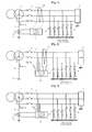
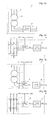
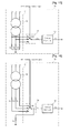
- FIG. 2 shows an embodiment, in which the secondary side connection of the transformer 1 is a Y-connection, the neutral point is grounded, phase voltage to the ground is detected using voltage detection lines 12 , 13 , and 14 for detecting a voltage component of the power line 3 , and a zero-phase current transformer 10 for detecting a zero-phase leakage current component of the power line 3 flowing to the ground is installed in the middle of the power line 3 .
- FIG. 3 shows an embodiment almost similar to the embodiment shown in FIG. 2 , in which the zero-phase current transformer 10 for detecting a zero-phase leakage current component of the power line 3 flowing to the ground is installed in the middle of the ground line 5 connected to the neutral point of the transformer 1 .
- FIG. 4 shows an embodiment almost similar to the embodiment shown in FIG. 2 , which describes that the leakage detecting apparatus can be used in a three-phase four-wire system where the neutral phase (N-phase) of the transformer is laid together.
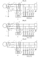
- FIG. 5 is an embodiment for describing that connection points of the voltage detection lines 12 , 13 , and 14 also can be implemented at a position further closer to the load than the zero-phase current transformer 10 , in which although the secondary side connection of the transformer 1 is a delta connection, T-phase is grounded.
- FIG. 6 is an embodiment of a non-grounding method, in which the secondary side connection of the transformer 1 is a delta connection
- FIG. 7 is an embodiment almost similar to the embodiment shown in FIG. 2 .
- FIG. 2 shows a method of detecting phase voltage
- line voltage is detected using the voltage detection lines 12 and 14 in the embodiment of FIG. 7 .
- FIGS. 2 to 7 like the embodiments of the voltage detecting means 30 that will be described below, there can be a variety of embodiments, such as an embodiment where the voltage component of one phase among three phases is detected and the other two voltage components are obtained by shifting the phase of the detected voltage component by 120 degrees, an embodiment where the voltage component of two phases among three phases is detected and the other one voltage component is obtained by shifting the phase of either of the detected voltage components by 120 degrees (or ⁇ 120 degrees), an embodiment where line voltage is detected instead of phase voltage, and an embodiment of a resistance grounded neutral system where resistors are installed between the neutral point of the transformer 1 and the ground 6 to limit the magnitude of ground fault current.
- FIGS. 8 to 11 show detailed circuit diagrams of the embodiments of the insulation detecting apparatus 20 shown in FIGS. 2 to 7 .
- FIGS. 8 and 9 show an embodiment where a three phase voltage component between the three-phase power line 3 and the ground is inputted into a phase comparing means 50 .
- FIGS. 10 and 11 show an embodiment where three phase voltage components between the three-phase power line 3 and the ground are sequentially inputted into the phase comparing means 50 one phase after another in response to an RST voltage control signal of the operation controller 70 .
- FIGS. 12 and 13 show detailed circuit diagrams of the embodiment of the voltage detecting means 30 shown in FIGS. 8 and 9 . If the voltage component of each of three phases of the power line 3 is inputted through the voltage detection lines 12 , 13 , and 14 , voltage of each phase is split by resistors Rv 1 and Rv 2 as shown in FIG. 12 .
- FIG. 13 shows an embodiment, where the voltage component of the power line 3 is detected after the voltage is lowered to a certain level by a transformer TR, and a voltage filter unit 33 is configured to extract a frequency component lower than a certain frequency or a frequency component of a commercial frequency band from the detected voltage component.
- FIGS. 14 to 21 show detailed circuit diagrams of the embodiments of the voltage detecting means 30 shown in FIGS. 10 and 11 , where a variety of embodiments for detecting a three phase or single-phase voltage component is shown. However, a variety of embodiments can be considered, such as an embodiment where a line voltage component is detected, an embodiment where a phase is shifted by ⁇ 120 degrees instead of using a 240° phase shift unit 312 , or the like. Describing FIGS. 14 to 21 further more, FIG.
- FIG. 14 shows an embodiment where if the voltage component of each of three phases of the power line 3 is inputted through the voltage detection lines 12 , 13 , and 14 , voltage of each phase is split by resistors Rv 1 and Rv 2 , and the voltage component of the power line 3 is detected by a phase selection unit 32 configured like a switch sw 1 for selecting one phase at a time among three RST phases, in response to an RST voltage control signal outputted from the operation controller 70 .
- a voltage filter unit 33 is configured to extract a frequency component lower than a certain frequency or a frequency component of a commercial frequency band from the voltage component of one of three phases detected by the phase selection unit 32 .
- FIG. 15 shows an embodiment where voltage is split by a transformer TR instead of the resistors used in the embodiment of FIG. 14 .
- FIG. 16 shows an embodiment where voltage is split by condensers Cv 1 and Cv 2 , not by the resistors used in the embodiment of FIG. 14 .
- FIG. 17 shows an embodiment where resistors Rv installed between the secondary side of the transformer TR and the ground are added to the embodiment of FIG. 15 , and there can be an embodiment where condensers are used instead of the resistors Rv in FIG. 17 .
- FIG. 18 shows an embodiment, where if the voltage component of each of three phases of the power line 3 is inputted through the voltage detection lines 12 , 13 , and 14 , the voltage is lowered to a certain level by a transformer TR, and a voltage filter unit 33 is coupled to extract a frequency component lower than a certain frequency or a frequency component of a commercial frequency band from the voltage component that is split again by an upper resistor Rv 1 and a resistor Rv 2 connected to the ground.
- the upper resistor Rv 1 is selected by the phase selection unit 32 for selecting one phase at a time among three RST phases in response to an RST voltage control signal outputted from the operation controller 70 .
- FIG. 19 shows an embodiment, where the transformer TR of the embodiment of FIG. 18 is not used, and the resistors Rv 1 used in this embodiment preferably have resistance higher than those of the resistors Rv 1 shown in FIGS. 12 to 18 .
- FIGS. 20 and 21 show embodiments, where in order to detect the voltage component of the power line 3 , only voltage component of one phase is detected, and voltage components of the other two phases are detected by shifting the phase of the voltage component detected by the voltage detecting unit 31 by 120 degrees and 240 degrees.
- the voltage component of R-phase for example, inputted through one voltage detection line 12 is split by two resistors Rv 1 and Rv 2 connected between the voltage detection line 12 and the ground.
- the split voltage component of R-phase is connected to a of the phase selection unit 32 , and voltage components of the other S-phase and T-phase respectively use a 120° phase shift unit 311 for shifting the voltage component of R-phase by 120 degrees and a 240° phase shift unit 312 for shifting the voltage component of R-phase by 240 degrees.
- the voltage component having a phase difference of 120 degrees from the voltage component of R-phase, which is outputted from the 120° phase shift unit 311 is connected to b of the phase selection unit 32 .
- the voltage component having a phase difference of 240 degrees from the voltage component of R-phase, which is outputted from the 240° phase shift unit 312 is connected to c of the phase selection unit 32 .
- the voltage component of the power line 3 is detected by the phase selection unit 32 configured like a switch sw 1 for selecting one phase at a time among three RST phases in response to an RST voltage control signal outputted from the operation controller 70 , and a voltage filter unit 33 is configured to extract a frequency component lower than a certain frequency or a frequency component of a commercial frequency band from the voltage component of one of three phases detected by the phase selection unit 32 .
- the resistors Rv 1 and Rv 2 preferably have high resistance.
- FIG. 21 shows an embodiment that is different from the embodiment of FIG. 20 only in that condensers Cv 1 and Cv 2 are used instead of the resistors Rv 1 and Rv 2 , where the condensers preferably have small capacitance.
- the 120° phase shift unit 311 and the 240° phase shift unit 312 are used in FIGS. 20 and 21 , there can be an embodiment where a ⁇ 120° (minus)120° phase shift unit for shifting a phase by ⁇ 120° is used instead of the 240° phase shift unit 312 .
- the voltage component of the power line 3 is detected by detecting two phase voltages or a line voltage using two voltage detection lines.
- FIG. 22 shows a detailed circuit diagram according to another embodiment of the leakage current detecting means 40 of FIGS. 8 to 11 , in which the leakage current detecting means 40 is configured in a sequence of a current-to-voltage conversion unit 41 , an amplification unit 42 , and a current filter unit 43 as shown in FIGS. 9 and 11 .
- FIG. 22 shows an embodiment where the leakage current detecting means 40 is configured in a different sequence of a current-to-voltage conversion unit 41 , a current filter unit 43 , and an amplification unit 42
- functions of the current-to-voltage conversion unit 41 and the amplification unit 42 are implemented as a single function.
- a variety of embodiments can be considered, such as an embodiment where the current-to-voltage conversion unit 41 is not implemented within the leakage current detecting means 40 , but is embedded in the secondary winding of the zero-phase current transformer 10 .
- FIGS. 23 to 25 are flowcharts illustrating the operation of the insulation detecting apparatus 20 of the present invention shown in FIGS. 8 to 11 or illustrating the insulation detecting method of the present invention.
- FIGS. 2 , 8 , 9 , and 23 of the present invention will be described first.
- the transformer 1 for transforming voltage provides power to the power line 3 through the switch 2 .
- Reference symbol 5 denotes a ground line for connecting the neutral point of the transformer to the ground 6 for safety.
- active component leakage current Ir of each of three phases flows between the power line 3 including a load 4 and the ground through an insulation resistor 9 that is directly related to insulation aging.
- reactive component leakage current Ic of each of three phases flows to the ground through electrostatic capacitance 8 that is not directly related to the insulation state, but generated if the power line 3 is long or an equipment such as a noise filter for reducing noises is installed at the input terminal of the load 4 .
- the active component leakage current Ir related to an insulation state of the power line 3 and the reactive component leakage current Ic that is not directly related to an insulation state, but flows between the power line 3 and the ground can be calculated.
- the zero-phase current transformer (ZCT) 10 is used to detect the zero-phase leakage current Io component, and the voltage detection lines 12 , 13 , and 14 are used to detect the voltage component of each of three phases between the power line 3 and the ground.
- the voltage detection lines 12 , 13 , and 14 and the secondary side of the zero-phase current transformer 10 are connected to the insulation detecting apparatus 20 shown in FIG. 8 .
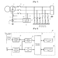
- FIG. 8 shows a block diagram of the insulation detecting apparatus used in FIGS. 2 to 7 according to a first embodiment of the insulation detecting apparatus.
- the insulation detecting apparatus 20 of the present invention comprises a voltage detecting means 30 for detecting a voltage component between a power line 3 and the ground, transforming the detected voltage component into voltage of a certain magnitude, and extracting a frequency component lower than a certain frequency or a frequency component of a certain band; a leakage current detecting means 40 for converting zero-phase leakage current Io component, which is detected at the secondary side of the zero-phase current transformer 10 for detecting zero-phase leakage current Io between the power line 3 including the load 4 and the ground, into a voltage component, amplifying the converted voltage component, and extracting a frequency component lower than a certain frequency or a frequency component of a commercial frequency band; a phase comparing means 50 for comparing each of three phases of an output value of the voltage detecting means 30 with a phase of an output value of the leakage current detecting means 40 ; an analog-to-digital conversion unit 60 for converting an analog component of the output value of the leakage current detecting means 40 into a digital component; an operation
- the voltage detecting means 30 for detecting a three phase voltage component of the power line 3 including a load comprises a voltage detecting unit 31 for transforming the three phase voltage component detected by the voltage detection lines 12 , 13 , and 14 into voltage of a certain magnitude, and a voltage filter unit 33 for extracting a frequency component lower than a certain frequency or a frequency component of a commercial frequency band from the three phase voltage component transformed by the voltage detecting unit 31 .
- the leakage current detecting means 40 comprises a current-to-voltage conversion unit 41 for converting leakage current component, which is detected at the secondary side of the zero-phase current transformer 10 for detecting the zero-phase leakage current Io between the power line 3 including the load 4 and the ground, into a voltage component, an amplification unit 42 for amplifying the leakage current component Ia converted by the current-to-voltage conversion unit 41 , and a current filter unit 43 for extracting a frequency component lower than a certain frequency or a frequency component of a commercial frequency band from a leakage current component corresponding to the zero-phase leakage current Io component amplified by the amplification unit 42 .
- the phase comparing means 50 includes a voltage component waveform shaping unit 51 for shaping the waveform of the voltage component of each of three phases outputted from the voltage detecting means 30 , a current component waveform shaping unit 52 for shaping the waveform of the leakage current component Io 1 corresponding to the zero-phase leakage current Io component outputted from the leakage current detecting means 40 , and a phase difference detecting unit 53 for detecting a phase difference between an output of the voltage component waveform shaping unit 51 and an output of the current component waveform shaping unit 52 . Only one output value of the leakage current detecting means 40 is inputted into the analog-to-digital conversion unit 60 in FIG. 8 .
- a voltage component value of the power line 3 is read to calculate both leakage current and insulation resistance, and if one component is inputted, only the leakage current is calculated and the insulation resistance is not calculated, choice of which will vary depending on embodiments.
- an embodiment where even the insulation resistance is calculated will be described to express a variety values needed for monitoring an insulation state.
- FIG. 9 showing a first embodiment of the insulation detecting apparatus 20
- FIG. 23 showing a flowchart of the insulation detecting apparatus 20 .
- a first insulation detecting method of the present invention shown in FIG. 23 capable of detecting an insulation state of a power line even when electrostatic capacitance between the power line and the ground is in an unbalanced state, as well as in a balanced state, comprises the steps of: allowing the leakage current detecting means 40 to detect a leakage current component Io 1 from a zero-phase current component detected at the secondary side of the zero-phase current transformer, allowing the voltage detecting means to detect a voltage component Vf of each of three phases by extracting only a frequency component, and detecting a phase difference of the leakage current component Io 1 from the voltage component Vf of each of three phases outputted from the voltage detecting means 30 ; calculating an in-phase component and a 90° phase-shifted component of the leakage current component Io 1 of each phase; calculating a 90° phase-shifted component zero value of each phase; verifying data on active component leakage current or reactive component leakage current of each phase calculated and stored in the memory unit in the step of calculating a 90°
- the input unit 82 sets a variety of data used in the insulation detecting apparatus 20 using a constitutional component such as a keypad or a switch 100 , in which the input unit has a function for setting a variety of data, e.g., a number address, an alarm setting value, and the like of each insulation detecting apparatus 20 if a plurality of insulation detecting apparatuses 20 is installed.
- a read operation is performed on a variety of data set by the input unit 82 , previously stored in the memory unit 86 , or inputted from a remote external site through the communication unit 90 110 .
- the zero-phase leakage current component Io detected at the secondary side of the zero-phase current transformer 10 shown in FIGS. 8 and 9 is converted into a voltage component by the current-to-voltage conversion unit 41 that converts current to voltage and amplified by the amplification unit 42 .
- a current component Io 1 corresponding to the zero-phase leakage current, from which a frequency component lower than a certain frequency or a frequency component of a commercial frequency band is extracted by the current filter unit 43 is outputted to the analog-to-digital conversion unit 60 and the phase comparing means 50 .
- the component Io 1 value corresponding to the zero-phase leakage current inputted into the analog-to-digital conversion unit 32 ( 60 ) is converted into a digital value, and the operation controller 70 reads and stores the digital value into the memory unit 86 .
- the voltage detecting unit 31 of FIG. 16 used in the embodiments shown in FIGS. 12 to 16 or another embodiment splits the voltage component of each of three phases between the power line 3 and the ground inputted through the voltage detection lines 12 , 13 , and 14 into voltages that can be used in the insulation detecting apparatus 20 , using resistors, condensers, or a transformer.
- the voltage component Vf of each of three phases (Vf_r of R-phase, Vf_s of S-phase, or Vf_t of T-phase), i.e., a split voltage from which a frequency component lower than a certain frequency or a frequency component of a commercial frequency band is extracted by the voltage filter unit 33 , is outputted to the phase comparing means 50 and the analog-to-digital conversion unit 60 .
- the voltage component Vf of each of three phases to the ground inputted into the analog-to-digital conversion unit 60 is converted into a digital value, and the operation controller 70 reads and stores the digital value into the memory unit 86 .
- the phase difference detecting unit 53 detects three phase differences between the three voltage components of three phases outputted from the voltage component waveform shaping unit 51 and the one leakage current component outputted from the current component waveform shaping unit 52 , i.e., a phase difference r of the leakage current component Io 1 for the voltage component of R-phase Vf_r, a phase difference s of the leakage current component Io 1 for the voltage component of S-phase Vf_s, and a phase difference t of the leakage current component Io 1 for the voltage component of R-phase Vf_t,
- the voltage between the three-phase power line 3 and the ground is 220V, and the frequency is 60 Hz.
- the values detected and stored in the memory unit 86 in the step of detecting the voltage component Vf, leakage current component Io 1 , and phase difference 120 are such that Io 1 is 76.3 mA, Vf_r, Vf_s, and Vf_t are 220 mV respectively, r is 104.8, s is ⁇ 15.2, and t is ⁇ 135.2.
- the leakage current component Io 1 and the phase differences r, s, and t detected and stored in the memory unit 86 in the step of detecting the voltage component Vf, leakage current component Io 1 , and phase difference 120 are read.
- an in-phase component cos value and a 90° phase-shifted component sin value for the voltage of the leakage current Io 1 corresponding to the zero-phase leakage current are calculated and stored in the memory unit 86 .
- the in-phase component leakage current of R-phase Io 1 rr is Io 1 ⁇ cos r
- the 90° phase-shifted component leakage current of R-phase Io 1 cr is Io 1 ⁇ sin r
- the in-phase component leakage current of S-phase Io 1 rs is Io 1 ⁇ cos s
- the 90° phase-shifted component leakage current of S-phase Io 1 cs is Io 1 ⁇ sin s
- the in-phase component leakage current of T-phase Io 1 rt is Io 1 ⁇ cos t
- the 90° phase-shifted component leakage current of T-phase Io 1 ct is Io 1 ⁇ sin t.
- Io 1 rr ⁇ 19.5 mA
- Io 1 cr 73.8 mA
- Io 1 rs 73.6 mA
- Io 1 cs ⁇ 20.0 mA
- Io 1 rt ⁇ 54.1 mA
- Io 1 ct ⁇ 53.8 mA
- Equation 1 The zero-phase leakage current Io component flowing between the power line 3 including the load 4 and the ground can be expressed as shown in Equation 1.
- Equation 1 the zero-phase leakage current for a three phase voltage component shown in Equation 1 is converted into a voltage component value of R-phase, and a value corresponding to the zero-phase leakage current component of a voltage component that is in-phase with the R-phase voltage, i.e., Io 1 rr , is expressed as shown in Equation 2, and a value corresponding to the zero-phase leakage current component of the voltage component that is 90° phase-shifted from the R-phase voltage, i.e., Io 1 cr , is expressed as shown in Equation 3.
- V ⁇ ⁇ and ⁇ ⁇ ⁇ I ⁇ ⁇ are ⁇ ⁇ vector ⁇ ⁇ functions .
- Equation ⁇ ⁇ 1 Irr - Irs 2 - Irt 2 - 3 2 ⁇ Ics + 3 2 ⁇ Ict ⁇ ⁇
- I ⁇ ⁇ is ⁇ ⁇ a ⁇ ⁇ ⁇ ⁇ real ⁇ ⁇ value .
- Equation ⁇ ⁇ 2 Icr - Ics 2 - Ict 2 + 3 2 ⁇ Irs - 3 2 ⁇ Irt ⁇ ⁇
- I ⁇ ⁇ is ⁇ ⁇ a ⁇ ⁇ real ⁇ ⁇ value .
- Equation ⁇ ⁇ 3 Irt ⁇ ⁇
- the relational expression between the in-phase component leakage current and the 90° phase-shifted component leakage currents of S-phase and T-phase is that they respectively have 120° and ⁇ 120° phase differences from the in-phase component leakage current and the 90° phase-shifted component leakage current of R-phase.
- the in-phase component leakage current of R-phase includes not only active component leakage current Irr flowing due to the insulation resistance of R-phase, but also active component leakage currents Irs and Irt flowing due to the insulation resistances of S-phase and T-phase and reactive component leakage currents Ics and Ict flowing due to the electrostatic capacitances of S-phase and T-phase.
- the 90° phase-shifted component leakage current of R-phase includes not only reactive component leakage current Irr flowing due to the electrostatic capacitance of R-phase, but also reactive component leakage currents Ics and Ict flowing due to the electrostatic capacitances of S-phase and T-phase and active component leakage currents Irs and Irt flowing due to the insulation resistances of S-phase and T-phase. Then, it can be conjectured from Equations 2 and 3 that an insulation state cannot be correctly obtained by a conventional method of detecting zero-phase leakage current Io generated by a zero-phase current transformer.
- a first method is for calculating a reactive component zero leakage current value with which the reactive component leakage current Ic becomes zero
- a second method is for calculating an active component zero leakage current value with which the active component leakage current Ir becomes zero
- a third method is for calculating an active component zero leakage current value and a reactive component zero leakage current value with which the reactive component leakage current Ic and the active component leakage current Ir become zero.
- a reactive component leakage current value generated by electrostatic capacitance with which a reactive component leakage current becomes zero is calculated for each of three phases. This value is calculated to understand that active component leakage current of which component flows at the secondary side of the zero-phase current converter 10 if the reactive component leakage current Ic generated by the electrostatic capacitance becomes zero. Describing it easily, it is to make reactive component leakage currents generated by electrostatic capacitances be balanced in all three phases. However, a predetermined value that is slightly larger than the zero value can be selected.
- a reactive component leakage current value of R-phase is calculated first to find out the phase and magnitude of reactive component zero leakage current Ic′ that should be additionally flown through the primary winding of the zero-phase current transformer 10 to make Io 1 cr zero, i.e., the value of Equation 3 becomes zero.
- Io 1 rr and Io 1 cr of R-phase, Io 1 rs and Io 1 cs of S-phase, and Io 1 rt and Io 1 ct of T-phase described in the above example and stored in the memory unit 86 are read.
- Icr′, Ics′, and Ict′ values are calculated so that the 90° phase-shifted reactive component leakage current of R-phase becomes zero, i.e., the value of Equation 3 becomes zero. If the Icr′, Ics′, and Ict′ values are put into Equation 2 and an in-phase component leakage current value Io 1 rr ′ of R-phase is calculated, Io 1 rr ′ becomes as shown in Equation 4. If the Icr′, Ics′, and Ict′ values are put into Equation 3 and a 90° phase-shifted component leakage current value Io 1 cr ′ of R-phase is calculated, Io 1 rr ′ becomes as shown in Equation 5.
- a second insulation detecting method of the present invention shown in FIG. 24 capable of detecting an insulation state of a power line even when electrostatic capacitance of the power line to the ground is in an unbalanced state, as well as in a balanced state, comprises the steps of: allowing the leakage current detecting means 40 to detect a leakage current component Io 1 from a zero-phase current component detected at the secondary side of the zero-phase current transformer, allowing the voltage detecting means to detect a voltage component Vf of each of three phases by extracting only a frequency component, and detecting a phase difference of the leakage current component Io 1 from the voltage component Vf of each of three phases outputted from the voltage detecting means 30 ; calculating an in-phase component and a 90° phase-shifted component of the leakage current component Io 1 of each phase; calculating an in-phase component zero value of each phase; verifying data on active component leakage current or reactive component leakage current of each phase calculated and stored in the memory unit in the step of calculating an in-phase component zero value
- Active component leakage current generated by insulation resistors Ir with which the active component leakage current value Ir becomes zero, is calculated for each of three phases. This value is calculated to understand that how much reactive component leakage current Ic flows at the secondary side of the zero-phase current converter 10 if the active component leakage current Ir generated by the insulation resistors becomes zero. Describing it easily, it is to make active component leakage currents generated by the insulation resistors Ir be balanced in all three phases. However, a predetermined value that is slightly larger than the zero value can be selected.
- An active component leakage current value of R-phase is calculated first to find out the phase of active component zero leakage current that should be additionally flown through the primary winding of the zero-phase current transformer 10 to make Io 1 rr zero, i.e., the value of Equation 2 becomes zero.
- Io 1 rr and Io 1 cr of R-phase, Io 1 rs and Io 1 cs of S-phase, and Io 1 rt and Io 1 ct of T-phase described in the above example and stored in the memory unit 86 are read. Then, Irs′, and Irt′ values are calculated so that the in-phase active component leakage current of R-phase becomes zero, i.e., the value of Equation 2 becomes zero.
- Irr′, Irs′, and Irt′ values are put into Equation 3 and a 90° phase-shifted component leakage current value Io 1 cr ′ of R-phase is calculated, Io 1 cr ′ becomes as shown in Equation 6. If the Irr′, Irs′, and Irt′ values are put into Equation 2 and an in-phase component leakage current value Io 1 rr ′ of R-phase is calculated, Io 1 rr ′ becomes as shown in Equation 7.
- a third insulation detecting method of the present invention shown in FIG. 25 is a combined method of FIGS. 23 and 24 .
- the steps already shown in FIGS. 23 and 24 will not be described, and the step of calculating a 90° phase-shifted component zero value of each phase 140 is described.
- a reactive leakage current value generated by electrostatic capacitance, with which a reactive component leakage current value becomes zero, is calculated for each of three phases. This value is calculated to understand that active component leakage current of which component flows at the secondary side of the zero-phase current converter 10 if the reactive component leakage current Ic generated by the electrostatic capacitance becomes zero. Describing it easily, it is to make reactive component leakage currents generated by the electrostatic capacitances be balanced in all three phases.
- a reactive component leakage current value of R-phase is calculated first to find out the phase and magnitude of reactive component zero leakage current Ic′ that should be additionally flown through the primary winding of the zero-phase current transformer 10 to make Io 1 cr zero, i.e., the value of Equation 3 becomes zero.
- Io 1 rr and Io 1 cr of R-phase, Io 1 rs and lobes of S-phase, and Io 1 rt and Io 1 ct of T-phase described in the above example and stored in the memory unit 86 are read. Then, Icr′, Ics′, and Ict′ values are calculated so that the 90° phase-shifted reactive component leakage current of R-phase becomes zero, i.e., the value of Equation 3 becomes zero. If the Icr′, Ics′, and Ict′ values are put into Equation 2 and an in-phase component leakage current value Io 1 rr ′ of R-phase is calculated, Io 1 rr ′ becomes as shown in Equation 8. If the Icr′, Ics′, and Ict′ values are put into Equation 3 and a 90° phase-shifted component leakage current value Io 1 cr ′ of R-phase is calculated, Io 1 cr ′ becomes as shown in Equation 9.
- an active component leakage current generated by insulation resistors is calculated for each of three phases. This value is calculated to understand that how much reactive component leakage current flows at the secondary side of the zero-phase current converter 10 if the active component leakage current generated by the insulation resistors becomes zero. Describing it easily, it is to make active component leakage currents generated by the insulation resistors Ir be balanced in all three phases.
- An active component leakage current value of R-phase is calculated first to find out the phase of active component zero leakage current Ir′ that should be additionally flown through the primary winding of the zero-phase current transformer 10 to make Io 1 rr zero, i.e., the value of Equation 2 becomes zero.
- Io 1 rr and Io 1 cr of R-phase, Io 1 rs and to of S-phase, and Io 1 rt and Io 1 ct of T-phase described in the above example and stored in the memory unit 86 are read. Then, Irr′, Irs′, and Irt′ values are calculated so that the in-phase active component leakage current of R-phase becomes zero, i.e., the value of Equation 2 becomes zero.
- Irr′, Irs′, and Irt′ values are put into Equation 3 and a 90° phase-shifted component leakage current value Io 1 cr ′ of R-phase is calculated, Io 1 cr ′ becomes as shown in Equation 10. If the Irr′, Irs′, and Irt′ values are put into Equation 2 and an in-phase component leakage current value Io 1 rr ′ of R-phase is calculated, Io 1 rr ′ becomes as shown in Equation 11.
- Reactive component zero leakage current Ic′ values calculated and stored in the memory unit 86 in the step of calculating a 90° phase-shifted component zero value of each phase 140 , with which the reactive component leakage current of each phase becomes zero, are combined by each case with Ir′ values calculated and stored in the memory unit 86 in the step of calculating an in-phase component zero value of each phase 150 , with which the active component leakage current of each phase becomes zero, and a combination where an Io value corresponding to the zero-phase leakage current becomes zero is searched.
- the Ic′ values and the Ir′ values are combined case by case, and the recalculated Io value becomes zero.
- information on a phase where insulation is the most poor e.g., S-phase in the example described above
- the insulation resistance R can be expressed as shown in Equation 12
- the electrostatic capacitance C can be expressed as shown in Equation 13.
- the voltage amplification coefficient is an amplification-related coefficient of the voltage detecting means 30
- the amplification-related co-efficient of the leakage current detecting means 40 including the zero-phase current transformer 10 is one.
- the data described above can be outputted to outside through the communication unit 90 .
- a variety of data described above is compared with an alarm setting value that is previously stored in the memory unit 86 , inputted through the input unit 82 , or received through the communication unit 90 . If the alarm setting value is larger than the active leakage current Ior or Ir, or smaller than the insulation resistance R, a warning alarm can be displayed on the display unit 84 or outputted through the communication unit 90 .
- FIGS. 23 to 25 are flowcharts illustrating an insulation detecting apparatus and an insulation detecting method that can be used in a second embodiment in the same manner as the first embodiment described referring to FIGS. 10 and 11 .
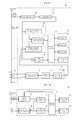
- FIG. 10 shows a block diagram of the insulation detecting apparatus used in FIGS. 2 to 7 according to a second embodiment of the insulation detecting apparatus.
- the insulation detecting apparatus 20 of the present invention comprises a voltage detecting means 30 for detecting a voltage component between the power line 3 and the ground, transforming the detected voltage component into voltage of a certain magnitude, and extracting a frequency component lower than a certain frequency or a frequency component of a commercial frequency band from a voltage component of a sequentially selected phase; a leakage current detecting means 40 for converting the zero-phase leakage current Io component, which is detected at the secondary side of the zero-phase current transformer 10 for detecting zero-phase leakage current Io between the power line 3 including a load 4 and the ground, into a voltage component, amplifying the converted voltage component, and extracting a frequency component lower than a certain frequency or a frequency component of a commercial frequency band; a phase comparing means 50 for comparing each of three phases of an output value of the voltage detecting means 30 with a phase of an output value of the leakage current detecting means 40 ; an analog-to-digital conversion unit 60 for converting an analog component of the output value of the leak
- the voltage detecting means 30 for detecting a three phase voltage component of the power line 3 including a load comprises a voltage detecting unit 31 for transforming the three phase voltage component detected by the voltage detection line 12 , 13 , and 14 into voltage of a certain magnitude, a phase selection unit 32 for sequentially selecting a voltage component of a phase from the three phase voltage component transformed by the voltage detecting unit 31 in response to an RST voltage control signal outputted from the operation controller 70 , and a voltage filter unit 33 for extracting a frequency component lower than a certain frequency or a frequency component of a commercial frequency band from the voltage component of the phase selected by the phase selection unit 32 .
- the leakage current detecting means 40 comprises a current-to-voltage conversion unit 41 for converting leakage current component, which is detected at the secondary side of the zero-phase current transformer 10 for detecting the zero-phase leakage current Io between the power line 3 including the load 4 and the ground, into a voltage component, an amplification unit 42 for amplifying the zero-phase leakage current component Io converted by the current-to-voltage conversion unit 41 , and a current filter unit 43 for extracting a frequency component lower than a certain frequency or a frequency component of a commercial frequency band from a leakage current component corresponding to the zero-phase leakage current Io component amplified by the amplification unit 42 .
- the phase comparing means 50 includes a voltage component waveform shaping unit 51 for shaping the waveform of the voltage component of each of three phases outputted from the voltage detecting means 30 , a current component waveform shaping unit 52 for shaping the waveform of the leakage current component corresponding to the zero-phase leakage current Io component outputted from the leakage current detecting means 40 , and a phase difference detecting unit 53 for detecting a phase difference of an output of the current component waveform shaping unit 52 from an output of the voltage component waveform shaping unit 51 .
- Only one output value of the leakage current detecting means 40 is inputted into the analog-to-digital conversion unit 60 in FIG. 10 .
- two analog components i.e., the output value of the leakage current detecting means 40 and the output value of the voltage detecting means 30 , are inputted into the analog-to-digital conversion unit 60 in FIG. 11 .
- the voltage component value of the power line 3 is read, and whether the read voltage component is used for calculating insulation resistance, as well as calculating a leakage current value, or whether only the leakage current value is calculated and the insulation resistance is not calculated will be different among embodiments.
- the insulation resistance will be calculated in order to express a variety of values for monitoring insulation conditions.
- FIG. 11 a second embodiment of the insulation detecting apparatus 20 shown FIG. 11 and a flowchart illustrating an operational flow of the insulation detecting apparatus 20 will be described in detail.
- the input unit 82 sets a variety of data used in the insulation detecting apparatus 20 using a constitutional component such as a keypad or a switch 100 , in which the input unit has a function for setting a variety of data, e.g., a number address, an alarm setting value, and the like of each insulation detecting apparatus 20 if a plurality of insulation detecting apparatuses 20 is installed.
- a read operation is performed on a variety of data set by the input unit 82 , previously stored in the memory unit 86 , or inputted from a remote external site through the communication unit 90 110 .
- the zero-phase leakage current component to detected at the secondary side of the zero-phase current transformer 10 as shown in FIGS. 10 and 11 is converted into a voltage component by the current-to-voltage conversion unit 41 that converts current to voltage and amplified by the amplification unit 42 .
- a current component Io 1 corresponding to the zero-phase leakage current from which a frequency component lower than a certain frequency or a frequency component of a commercial frequency band is extracted by the current filter unit 43 is outputted to the analog-to-digital conversion unit 60 and the phase comparing means 50 .
- the component Io 1 value corresponding to the zero-phase leakage current inputted into the analog-to-digital conversion unit 32 ( 60 ) is converted into a digital value, and the operation controller 70 reads and stores the digital value into the memory unit 86 .
- the voltage detecting unit 31 used in the embodiments shown in FIGS. 14 to 21 splits the voltage component of each of three phases between the power line 3 and the ground inputted through the voltage detection lines 12 , 13 , and 14 into voltages that can be used in the insulation detecting apparatus 20 , using resistors, condensers, a transformer, the 120° phase shift unit 311 , or the 240° phase shift unit 312 .
- the switch sw 1 in the phase selection unit 32 is connected to terminal a in response to an RST voltage control signal for selecting R-phase received from the operation controller 70 , the voltage component of R-phase is inputted into the voltage filter unit 33 .
- the voltage component Vf value (Vf_r of R-phase) i.e., the voltage component of R-phase selected by the phase selection unit 32 from which a frequency component lower than a certain frequency or a frequency component of a commercial frequency band is extracted by the voltage filter unit 33 , is outputted to the phase comparing means 50 and the analog-to-digital conversion unit 60 .
- the voltage component Vf_r value to the ground inputted into the analog-to-digital conversion unit 60 is converted into a digital value, and the operation controller 70 reads and stores the digital value into the memory unit 86 .
- the phase difference detecting unit 53 detects a phase difference between the voltage component outputted from the voltage component waveform shaping unit 51 and the one leakage current component outputted from the current component waveform shaping unit 52 , i.e., a phase difference r of the leakage current component Io 1 for the voltage component Vf_r of R-phase, and the operation controller 70 reads and stores the phase difference into the memory unit 86 .
- the switch sw 1 in the phase selection unit 32 is connected to terminal b in response to an RST voltage control signal for selecting S-phase received from the operation controller 70 , the voltage component of S-phase is inputted into the voltage filter unit 33 .
- the voltage component Vf value (Vf_s of S-phase) i.e., the voltage component of S-phase selected by the phase selection unit 32 from which a frequency component lower than a certain frequency or a frequency component of a commercial frequency band is extracted by the voltage filter unit 33 , is outputted to the phase comparing means 50 and the analog-to-digital conversion unit 60 .
- the voltage component Vf_s value to the ground inputted into the analog-to-digital conversion unit 60 is converted into a digital value, and the operation controller 70 reads and stores the digital value into the memory unit 86 .
- the phase difference detecting unit 53 detects a phase difference between the voltage component outputted from the voltage component waveform shaping unit 51 and the one leakage current component outputted from the current component waveform shaping unit 52 , i.e., a phase difference s of the leakage current component Io 1 for the voltage component Vf_s of S-phase, and the operation controller 70 reads and stores the phase difference into the memory unit 86 .
- the switch sw 1 in the phase selection unit 32 is connected to terminal c in response to an RST voltage control signal for selecting T-phase received from the operation controller 70 , the voltage component of T-phase is inputted into the voltage filter unit 33 .
- the voltage component Vf value (Vf_t of T-phase) i.e., the voltage component of T-phase selected by the phase selection unit 32 from which a frequency component lower than a certain frequency or a frequency component of a commercial frequency band is extracted by the voltage filter unit 33 , is outputted to the phase comparing means 50 and the analog-to-digital conversion unit 60 .
- the voltage component Vf_t value to the ground inputted into the analog-to-digital conversion unit 60 is converted into a digital value, and the operation controller 70 reads and stores the digital value into the memory unit 86 .
- the phase difference detecting unit 53 detects a phase difference between the voltage component outputted from the voltage component waveform shaping unit 51 and the one leakage current component outputted from the current component waveform shaping unit 52 , i.e., a phase difference t of the leakage current component Io 1 for the voltage component Vf_t of T-phase, and the operation controller 70 reads and stores the phase difference into the memory unit 86 .
- the voltage between the three-phase power line 3 and the ground is 220V, and the frequency is 60 Hz.
- the values detected and stored in the memory unit 86 in the step of detecting the voltage component Vf, leakage current component Io 1 , and phase difference 120 are such that Io 1 is 76.3 mA, Vf_r, Vf_s, and Vf_t are 220 mV respectively, r is 104.8, s is ⁇ 15.2, and t is ⁇ 135.2.
- the leakage current component Io 1 and the phase differences r, s, and t detected and stored in the memory unit 86 in the step of detecting the voltage component Vf, leakage current component Io 1 , and phase difference 120 are read.
- an in-phase component cos value and a 90° phase-shifted component sin value for the voltage of the leakage current Io 1 corresponding to the zero-phase leakage current are calculated and stored in the memory unit 86 .
- the in-phase component leakage current of R-phase Io 1 rr is Io 1 ⁇ cos r
- the 90° phase-shifted component leakage current of R-phase Io 1 cr is Io 1 ⁇ sin r
- the in-phase component leakage current of S-phase Io 1 rs is Io 1 ⁇ cos s
- the 90° phase-shifted component leakage current of S-phase Io 1 cs is Io 1 ⁇ sin s
- the in-phase component leakage current of T-phase Io 1 rt is Io 1 ⁇ cos t
- the 90° phase-shifted component leakage current of T-phase Io 1 ct is Io 1 ⁇ sin t.
- Io 1 rr ⁇ 19.5 mA
- Io 1 cr 73.8 mA
- Io 1 rs 73.6 mA
- Io 1 cs ⁇ 20.0 mA
- Io 1 rt ⁇ 54.1 mA
- Io 1 ct ⁇ 53.8 mA
- Equation 14 The zero-phase leakage current to component flowing between the power line 3 including the load 4 and the ground can be expressed as shown in Equation 14.
- Equation 14 the zero-phase leakage current for a three phase voltage component shown in Equation 14 is converted to a voltage component value of R-phase, and a value corresponding to the zero-phase leakage current component of a voltage component that is in-phase with the R-phase voltage, i.e., Io 1 rr , is expressed as shown in Equation 15, and a value corresponding to the zero-phase leakage current component of the voltage component that is 90° phase-shifted from the R-phase voltage, i.e., Io 1 cr , is expressed as shown in Equation 16.
- V ⁇ ⁇ and ⁇ ⁇ ⁇ I ⁇ ⁇ are ⁇ ⁇ vector ⁇ ⁇ functions .
- Equation ⁇ ⁇ 14 Irr - Irs 2 - Irt 2 - 3 2 ⁇ Ics + 3 2 ⁇ Ict ⁇ ⁇
- I ⁇ ⁇ is ⁇ ⁇ a ⁇ ⁇ ⁇ ⁇ real ⁇ ⁇ value .
- Equation ⁇ ⁇ 15 Icr - Ics 2 - Ict 2 + 3 2 ⁇ Irs - 3 2 ⁇ Irt ⁇ ⁇
- I ⁇ ⁇ is ⁇ ⁇ a ⁇ ⁇ real ⁇ ⁇ value .
- Equation ⁇ ⁇ 16 >
- the relational expression between the in-phase component leakage current and the 90° phase-shifted component leakage current of S-phase and T-phase is that they respectively have 120° and ⁇ 120° phase differences from the in-phase component leakage current and the 90° phase-shifted component leakage current of R-phase.
- the in-phase component leakage current of R-phase includes not only active component leakage current Irr flowing due to the insulation resistance of R-phase, but also active component leakage currents Irs and Irt flowing due to the insulation resistances of S-phase and T-phase and reactive component leakage currents Ics and Ict flowing due to the electrostatic capacitances of S-phase and T-phase.
- the 90° phase-shifted component leakage current of R-phase includes not only reactive component leakage current Icr flowing due to the electrostatic capacitance of R-phase, but also reactive component leakage currents Ics and Ict flowing due to the electrostatic capacitances of S-phase and T-phase and active component leakage currents Irs and Irt flowing due to the insulation resistances of S-phase and T-phase. Then, it can be conjectured from Equations 15 and 16 that an insulation state cannot be correctly obtained by a conventional method of detecting zero-phase leakage current Io generated by a zero-phase current transformer.
- a reactive component leakage current value generated by electrostatic capacitance with which a reactive component leakage current becomes zero is calculated for each of three phases. This value is calculated to understand that active component leakage current of which component flows at the secondary winding of the zero-phase current converter 10 if the reactive component leakage current Ic generated by the electrostatic capacitance becomes zero. Describing it easily, it is to make reactive component leakage currents generated by electrostatic capacitances be balanced in all three phases.
- a reactive component leakage current value of R-phase is calculated first to find out the phase and magnitude of reactive component zero leakage current Ic′ that should be additionally flown through the primary winding of the zero-phase current transformer 10 to make Io 1 cr zero, i.e., the value of Equation 16 becomes zero.
- Io 1 rr and Io 1 cr of R-phase, Io 1 rs and Io 1 cs of S-phase, and Io 1 rt and Io 1 ct of T-phase described in the above example and stored in the memory unit 86 are read. Then. Icr′, Ics′, and Ict′ values are calculated so that the 90° phase-shifted reactive component leakage current of R-phase becomes zero, i.e., the value of Equation 3 becomes zero. If the Icr′, Ics′, and Ict′ values are put into Equation 15 and an in-phase component leakage current value Io 1 rr ′ of R-phase is calculated, Io 1 rr ′ becomes as shown in Equation 17. If the Icr′, Ics′, and Ict′ values are put into Equation 16 and a 90° phase-shifted component leakage current value Io 1 cr ′ of R-phase is calculated, Io 1 cr ′ becomes as shown in Equation 18.
- active component leakage current generated by insulation resistors Ir is calculated for each of three phases. This value is calculated to understand that how much reactive component leakage current Ic flows at the secondary side of the zero-phase current converter 10 if the active component leakage current Ir generated by the insulation resistors becomes zero.
- An active component leakage current value of R-phase is calculated first to find out the phase of active component zero leakage current Ir′ that should be additionally flown through the primary winding of the zero-phase current transformer 10 to make Io 1 rr zero, i.e., the value of Equation 2 becomes zero.
- Io 1 rr and Io 1 cr of R-phase, Io 1 rs and Io 1 cs of S-phase, and Io 1 rt and Io 1 ct of T-phase described in the above example and stored in the memory unit 86 are read. Then, Irr′, Irs′, and Irt′ values are calculated so that the in-phase active component leakage current of R-phase becomes zero, i.e., the value of Equation 15 becomes zero. If the Irr′, Irs′, and Irt′ values are put into Equation 16 and a 90° phase-shifted component leakage current value Io 1 cr ′ of R-phase is calculated, Io 1 cr ′ becomes as shown in Equation 19.
- Irr′, Irs′, and Irt′ values are put into Equation 15 and an in-phase component leakage current value Io 1 rr ′ of R-phase is calculated, Io 1 rr ′ becomes as shown in Equation 20.
- a reactive leakage current value generated by electrostatic capacitance with which a reactive component leakage current value becomes zero is calculated for each of three phases. This value is calculated to understand that active component leakage current of which component flows at the secondary side of the zero-phase current converter 10 if the reactive component leakage current Ic generated by the electrostatic capacitance becomes zero. Describing it easily, it is to make reactive component leakage currents generated by the electrostatic capacitances be balanced in all three phases.
- a reactive component leakage current value of R-phase is calculated first to find out the phase and magnitude of reactive component zero leakage current Ic′ that should be additionally flown through the primary winding of the zero-phase current transformer 10 to make Io 1 cr zero, i.e., the value of Equation 20 becomes zero.
- Io 1 rr and Io 1 cr of R-phase, Io 1 rs and Io 1 cs of S-phase, and Io 1 rt and Io 1 ct of T-phase described in the above example and stored in the memory unit 86 are read. Then, Icr′, Ics′, and Ict′ values are calculated so that the 90° phase-shifted reactive component leakage current of R-phase becomes zero, i.e., the value of Equation 16 becomes zero. If the Icr′, Ics′, and Ice values are put into Equation 15 and an in-phase component leakage current value Io 1 rr ′ of R-phase is calculated, Io 1 rr ′ becomes as shown in Equation 21.
- Icr′, Ics′, and Ict′ values are put into Equation 16 and a 90° phase-shifted component leakage current value Io 1 cr ′ of R-phase is calculated, Io 1 cr ′ becomes as shown in Equation 22.
- the step of calculating an in-phase component zero value of each phase 150 of FIG. 25 is described.
- an active component leakage current generated by insulation resistors with which the active component leakage current value becomes zero, is calculated for each of three phases. This value is calculated to understand that how much reactive component leakage current flows at the secondary side of the zero-phase current converter 10 if the active component leakage current generated by the insulation resistors becomes zero. Describing it easily, it is to make active component leakage currents generated by the insulation resistors Ir be balanced in all three phases.
- An active component leakage current value of R-phase is calculated first to find out the phase of active component zero leakage current Ir′ that should be additionally flown through the primary winding of the zero-phase current transformer 10 to make Io 1 rr zero, i.e., the value of Equation 11 becomes zero.
- Io 1 rr and Io 1 rr of R-phase, Io 1 rs and Io 1 cs of S-phase, and Io 1 rt and Io 1 ct of T-phase described in the above example and stored in the memory unit 86 are read.
- Irr′, Irs′, and Irt′ values are calculated so that the in-phase active component leakage current becomes zero, i.e., the value of Equation 15 becomes zero. If the Irr′, Irs′, and Irt′ values are put into Equation 16 and a 90° phase-shifted component leakage current value Io 1 cr ′ of R-phase is calculated, Io 1 cr ′ becomes as shown in Equation 23. If the Irr′, Irs′, and Irt′ values are put into Equation 15 and an in-phase component leakage current value Io 1 rr ′ of R-phase is calculated, Io 1 rr ′ becomes as shown in Equation 24.
- Reactive component zero leakage current Ic′ values calculated and stored in the memory unit 86 in the step of calculating a 90° phase-shifted component zero value of each phase 140 , with which the reactive component leakage current of each phase becomes zero, are combined by each case with Ir′ values calculated and stored in the memory unit 86 in the step of calculating an in-phase component zero value of each phase 150 , with which the active component leakage current of each phase becomes zero, and a combination where an Io value corresponding to the zero-phase leakage current becomes zero is searched.
- the Ic′ values and the Ir′ values are combined case by case, and the recalculated Io value becomes zero.
- information on a phase where insulation is the most poor e.g., S-phase in the example described above
- the insulation resistance R can be expressed as shown in Equation 13
- the electrostatic capacitance C can be expressed as shown in Equation 14.
- the voltage amplification coefficient is an amplification-related coefficient of the voltage detecting means 30
- the amplification-related co-efficient of the leakage current detecting means 40 including the zero-phase current transformer 10 is one.
- the data described above can be outputted to outside through the communication unit 90 .
- a variety of data described above is compared with an alarm setting value that is previously stored in the memory unit 86 , inputted through the input unit 82 , or received through the communication unit 90 . If the alarm setting value is larger than the active leakage current Ior or Ir, or smaller than the insulation resistance R, warning alarm can be displayed on the display unit 84 or outputted through the communication unit 90 .
- the leakage detecting apparatus of the present invention can be embodied in a variety of forms, i.e., the leakage detecting apparatus can be embodied in a system where the secondary side connection of the transformer 1 is a Y-connection or a delta-connection, in a three-phase three-wire or three-phase four-wire system, in a non-grounding system, or in a system where the voltage component of the power line 3 is implemented by detecting phase voltage or line voltage.
- connection diagram of the second embodiment of the insulation detecting apparatus according to the present invention shown in FIG. 3 and the connection diagram of the first embodiment shown in FIG. 2 is that the zero-phase current transformer 10 , such as ZCT for detecting zero-phase leakage current Io, is installed in the middle of the power line 3 to detect the insulation state of the power line 3 including the load 4 in the embodiment of FIG. 2 , whereas the zero-phase current transformer 10 is installed in the middle of the ground line 5 of the transformer 1 in the embodiment of FIG. 3 , and the other aspects of the two embodiments are the same.
- ZCT for detecting zero-phase leakage current Io
- connection diagram of the third embodiment of the insulation detecting apparatus according to the present invention shown in FIG. 4 is a connection diagram for describing that the connection diagram of the third embodiment is almost the same as that of the first embodiment shown in FIG. 2 and the insulation detecting apparatus can be embodied in a three-phase four-wire system where the neutral phase (N-phase) is used, and the operational flow and detecting method of the insulation detecting apparatus 20 is the same as those described above.
- connection diagram of the fourth embodiment of the insulation detecting apparatus according to the present invention shown in FIG. 5 is a connection diagram for describing that the insulation detecting apparatus can be embodied in a power line 3 where the secondary side connection of the transformer 1 is a delta connection and a phase of the delta connection is grounded, and the operational flow and detecting method of the insulation detecting apparatus 20 is the same as those described above.
- connection diagram of the fifth embodiment of the insulation detecting apparatus according to the present invention shown in FIG. 6 is a connection diagram for describing that the insulation detecting apparatus can be embodied in a non-grounding system where the secondary side connection of the transformer 1 is a delta connection that is not grounded, and the operational flow and detecting method of the insulation detecting apparatus 20 is the same as those described above.
- connection diagram of the sixth embodiment of the insulation detecting apparatus is a connection diagram for describing that the insulation state of the power line 3 can be monitored by detecting line voltage, and the operational flow and detecting method of the insulation detecting apparatus 20 is the same as those described above.
- the leakage current detecting means 40 used in the aforementioned embodiments of the present invention shown in FIGS. 9 and 11 is configured in the sequence of detecting a leakage current component through the zero-phase current transformer 10 , converting the detected leakage current component to a voltage component in the current-to-voltage conversion unit 41 , amplifying a value converted to a voltage component through the amplification unit 42 , and filtering the amplified value through the current filter unit 43 .
- FIG. 9 another embodiment of the leakage current detecting means shown in FIG.
- the 22 is configured in the sequence of detecting a leakage current component through the zero-phase current converter 10 , converting the detected leakage current component to a voltage component in the current-to-voltage conversion unit 41 , filtering a value converted to a voltage component in the current filter unit 43 , and then amplifying the filtered value through the amplification unit 42 .
- the voltage detecting unit 31 of the power line 3 is configured inside of the insulation detecting apparatus 20 to detect a voltage component in the embodiments of the present invention, there can be other embodiments where a part having a function of the voltage detecting unit 31 is configured outside of the insulation detecting apparatus 20 .
- the current-to-voltage conversion unit 41 is configured inside of the insulation detecting apparatus 20 to detect leakage current, if an electronic component element such as a resistor is directly connected to the secondary side of the zero-phase current converter 10 , there can be other embodiments where a part having a function of the current-to-voltage conversion unit 41 is configured outside of the insulation detecting apparatus 20 .
- the amplification unit 42 is configured to have a function of the current-to-voltage conversion unit 41 .
- resistance or capacitance of the resistors or capacitors used in the voltage detecting unit 31 is the same for all three phases in the embodiments of the present invention, there can be another embodiment where previously known different values can be applied to three phases respectively.
- phase angles and leakage current of each phase are measured using a power factor meter, leakage current meter, or wattmeter, which has the same functions as those of the embodiments of the present invention, together with capability of measuring phase angles and leakage current.
Landscapes
- Physics & Mathematics (AREA)
- General Physics & Mathematics (AREA)
- Testing Of Short-Circuits, Discontinuities, Leakage, Or Incorrect Line Connections (AREA)
- Emergency Protection Circuit Devices (AREA)
- Measurement Of Resistance Or Impedance (AREA)
Applications Claiming Priority (4)
| Application Number | Priority Date | Filing Date | Title |
|---|---|---|---|
| KR10-2006-0077160 | 2006-08-16 | ||
| KR1020060077160A KR100817890B1 (ko) | 2006-08-16 | 2006-08-16 | 전선로의 절연검출장치 및 절연검출방법 |
| KRPCT/KR2007/003913 | 2007-08-16 | ||
| PCT/KR2007/003913 WO2008020713A1 (en) | 2006-08-16 | 2007-08-16 | Insulation monitoring system & insulation detecting method for electric power supply system |
Publications (1)
| Publication Number | Publication Date |
|---|---|
| US20100131215A1 true US20100131215A1 (en) | 2010-05-27 |
Family
ID=39082219
Family Applications (1)
| Application Number | Title | Priority Date | Filing Date |
|---|---|---|---|
| US12/377,110 Abandoned US20100131215A1 (en) | 2006-08-16 | 2007-08-16 | Insulation monitoring system & insulation detecting method for electric power supply system |
Country Status (4)
| Country | Link |
|---|---|
| US (1) | US20100131215A1 (ko) |
| JP (1) | JP2010500864A (ko) |
| KR (1) | KR100817890B1 (ko) |
| WO (1) | WO2008020713A1 (ko) |
Cited By (21)
| Publication number | Priority date | Publication date | Assignee | Title |
|---|---|---|---|---|
| US20100237704A1 (en) * | 2009-03-23 | 2010-09-23 | Honda Motor Co., Ltd. | Single-phase to n-phase converter and power conversion system |
| US20110037613A1 (en) * | 2009-08-14 | 2011-02-17 | Jadavpur University | Remote monitoring system |
| US20110163759A1 (en) * | 2010-01-06 | 2011-07-07 | Yamatake Corporation | Circuit fault detecting device and method |
| US20110320146A1 (en) * | 2009-03-05 | 2011-12-29 | Mitsubishi Electric Corporation | Device for detecting insulation degradation |
| CN103134992A (zh) * | 2011-11-25 | 2013-06-05 | 财团法人工业技术研究院 | 绝缘阻抗估计装置及估计方法 |
| CN103308755A (zh) * | 2013-05-30 | 2013-09-18 | 中达电通股份有限公司 | 高压直流远程供电系统的绝缘检测装置及方法 |
| US20140021962A1 (en) * | 2012-07-20 | 2014-01-23 | Viper Subsea Technology Limited | Subsea Deployed Apparatus and Method |
| CN103869184A (zh) * | 2014-02-11 | 2014-06-18 | 广东电网公司电力科学研究院 | 基于pmu数据的单回输电线路零序参数抗差辨识方法 |
| WO2014101656A1 (zh) * | 2012-12-31 | 2014-07-03 | 中国矿业大学 | 煤矿高压电网绝缘状态监测方法 |
| US20140253091A1 (en) * | 2011-10-28 | 2014-09-11 | Mitsubishi Electric Corporation | Determination device, determination method, and non-transitory recording medium |
| CN105021879A (zh) * | 2014-04-28 | 2015-11-04 | Ls产电株式会社 | 用于监测无变压器的光伏逆变器的泄漏电流的装置 |
| KR20160023630A (ko) * | 2013-06-26 | 2016-03-03 | 후지 덴키 기기세이교 가부시끼가이샤 | 절연 감시 장치 |
| US20160178687A1 (en) * | 2013-08-06 | 2016-06-23 | Mitsubishi Electric Corporation | Phase control device |
| US20160291063A1 (en) * | 2013-11-12 | 2016-10-06 | James Blake | Power transformers using optical current sensors |
| US20170307675A1 (en) * | 2014-09-26 | 2017-10-26 | Tanashin Denki Co., Ltd. | Leakage current calculation device and leakage current calculation method |
| JP2018004329A (ja) * | 2016-06-28 | 2018-01-11 | 株式会社トーエネック | 対地静電容量測定装置および対地静電容量測定方法 |
| CN112039095A (zh) * | 2020-08-24 | 2020-12-04 | 武汉大盛源电力有限公司 | 一种三相不平衡治理系统及方法 |
| DE102019127579B3 (de) * | 2019-10-14 | 2021-01-14 | Dr. Ing. H.C. F. Porsche Aktiengesellschaft | Überwachungsvorrichtung für Ableitströme |
| US11276994B2 (en) * | 2013-02-20 | 2022-03-15 | Viper Innovations Ltd | Rejuvenation of subsea electrical cable insulation |
| CN117192189A (zh) * | 2023-11-03 | 2023-12-08 | 浙江正泰物联技术有限公司 | 三相电压测量电路、方法以及三相电表 |
| EP4300742A1 (en) * | 2022-06-28 | 2024-01-03 | Bestway Inflatables & Material Corp. | Electric leakage protection device for pool apparatus, and pool apparatus |
Families Citing this family (12)
| Publication number | Priority date | Publication date | Assignee | Title |
|---|---|---|---|---|
| JP2010060329A (ja) * | 2008-09-01 | 2010-03-18 | Patokkusu Japan Kk | 電路及び電気機器の漏洩電流測定装置及び方法 |
| CN102237669A (zh) * | 2010-04-27 | 2011-11-09 | 上海华建电力设备股份有限公司 | 微机线路保护监控装置 |
| CN102539931B (zh) * | 2012-03-07 | 2014-03-26 | 深圳市英威腾电气股份有限公司 | 一种绝缘检测方法及绝缘检测装置 |
| CN103384061A (zh) * | 2012-05-03 | 2013-11-06 | 上海华建电力设备股份有限公司 | 一种微机线路保护监控装置 |
| CN102680791B (zh) * | 2012-05-24 | 2015-05-13 | 重庆市防雷中心 | 一种降阻剂电阻率和工频电流耐受试验自动测试系统 |
| WO2015053479A1 (ko) * | 2013-10-10 | 2015-04-16 | 한국수력원자력 주식회사 | 원자력발전소 연결 선로 결상 검출장치 및 그 결상 검출방법 |
| JP6725104B2 (ja) * | 2016-04-04 | 2020-07-15 | 新日本無線株式会社 | 漏電検出装置 |
| KR101840980B1 (ko) * | 2017-09-29 | 2018-05-04 | 전명수 | 전기기기의 절연열화 진단장치 및 진단방법 |
| KR101986221B1 (ko) * | 2017-12-04 | 2019-09-30 | 한국전기안전공사 | 3상4선식 전기설비의 활선상태 절연저항 측정 방법 및 장치 |
| KR102054937B1 (ko) * | 2018-09-27 | 2019-12-12 | 에이디파워 주식회사 | 활선 절연 저항 측정 장치 |
| CN112684304B (zh) * | 2020-12-02 | 2021-09-24 | 西南交通大学 | 一种冲击电压下车载牵引变压器绕组绝缘状态的评估方法 |
| JP7353002B1 (ja) | 2023-05-08 | 2023-09-29 | 株式会社SoBrain | 計測装置、計測方法および計測プログラム |
Citations (11)
| Publication number | Priority date | Publication date | Assignee | Title |
|---|---|---|---|---|
| US2752590A (en) * | 1954-03-01 | 1956-06-26 | Specialties Dev Corp | Insulation failure detector for electric cables |
| US2805391A (en) * | 1952-05-23 | 1957-09-03 | Sthn United Telephone Cables | Testing of the insulation of electric conductors |
| US2837714A (en) * | 1954-03-31 | 1958-06-03 | Hill George Leslie | Method of testing electrical insulation |
| US2916697A (en) * | 1955-07-05 | 1959-12-08 | Bourns Inc | Insulation resistance measuring circuit |
| US3005150A (en) * | 1960-11-15 | 1961-10-17 | Samuel H Behr | Apparatus for determining the condition of electrical insulation |
| US3071724A (en) * | 1960-03-28 | 1963-01-01 | Gen Electric | Method and apparatus for testing electrical insulation |
| US4638242A (en) * | 1981-07-01 | 1987-01-20 | Toyo Communication Equipment Co., Ltd. | Method and device for measuring insulation deterioration of electric line |
| US4857830A (en) * | 1988-11-03 | 1989-08-15 | Toyo Communication Equipment Co., Ltd. | Method for measuring insulation resistance of electric line |
| US5216226A (en) * | 1991-03-04 | 1993-06-01 | Mitsubishi Denki Kabushiki Kaisha | Apparatus for preventing and predicting deterioration of insulation in an electric equipment |
| US20050218907A1 (en) * | 2004-03-31 | 2005-10-06 | General Electric Company | System and method for on line monitoring of insulation condition for dc machines |
| US20060020406A1 (en) * | 2001-10-04 | 2006-01-26 | Hitachi, Ltd. | Leakage current or resistance measurement method, and monitoring apparatus and monitoring system of the same |
Family Cites Families (5)
| Publication number | Priority date | Publication date | Assignee | Title |
|---|---|---|---|---|
| JP3009323B2 (ja) * | 1994-03-15 | 2000-02-14 | 三菱電機ビルテクノサービス株式会社 | 電力ケーブルの絶縁診断装置 |
| JP3430627B2 (ja) * | 1994-05-18 | 2003-07-28 | 住友電気工業株式会社 | 電力ケーブルの絶縁状態を活線下で監視する絶縁監視方法及び装置 |
| KR100196299B1 (ko) | 1996-01-31 | 1999-06-15 | 권문구 | 전력 케이블의 절연열화 측정장치 |
| JP2005227132A (ja) * | 2004-02-13 | 2005-08-25 | Meidensha Corp | 絶縁状態監視装置、および絶縁状態監視方法 |
| KR200401675Y1 (ko) | 2005-08-26 | 2005-11-21 | 김보경 | 저압 전로의 활선 절연감시장치 |
-
2006
- 2006-08-16 KR KR1020060077160A patent/KR100817890B1/ko not_active IP Right Cessation
-
2007
- 2007-08-16 US US12/377,110 patent/US20100131215A1/en not_active Abandoned
- 2007-08-16 WO PCT/KR2007/003913 patent/WO2008020713A1/en active Application Filing
- 2007-08-16 JP JP2009524555A patent/JP2010500864A/ja not_active Withdrawn
Patent Citations (13)
| Publication number | Priority date | Publication date | Assignee | Title |
|---|---|---|---|---|
| US2805391A (en) * | 1952-05-23 | 1957-09-03 | Sthn United Telephone Cables | Testing of the insulation of electric conductors |
| US2752590A (en) * | 1954-03-01 | 1956-06-26 | Specialties Dev Corp | Insulation failure detector for electric cables |
| US2837714A (en) * | 1954-03-31 | 1958-06-03 | Hill George Leslie | Method of testing electrical insulation |
| US2916697A (en) * | 1955-07-05 | 1959-12-08 | Bourns Inc | Insulation resistance measuring circuit |
| US3071724A (en) * | 1960-03-28 | 1963-01-01 | Gen Electric | Method and apparatus for testing electrical insulation |
| US3005150A (en) * | 1960-11-15 | 1961-10-17 | Samuel H Behr | Apparatus for determining the condition of electrical insulation |
| US4638242A (en) * | 1981-07-01 | 1987-01-20 | Toyo Communication Equipment Co., Ltd. | Method and device for measuring insulation deterioration of electric line |
| US4857830A (en) * | 1988-11-03 | 1989-08-15 | Toyo Communication Equipment Co., Ltd. | Method for measuring insulation resistance of electric line |
| US5216226A (en) * | 1991-03-04 | 1993-06-01 | Mitsubishi Denki Kabushiki Kaisha | Apparatus for preventing and predicting deterioration of insulation in an electric equipment |
| US20060020406A1 (en) * | 2001-10-04 | 2006-01-26 | Hitachi, Ltd. | Leakage current or resistance measurement method, and monitoring apparatus and monitoring system of the same |
| US7353123B2 (en) * | 2001-10-04 | 2008-04-01 | Hitachi, Ltd. | Leakage current or resistance measurement method, and monitoring apparatus and monitoring system of the same |
| US20050218907A1 (en) * | 2004-03-31 | 2005-10-06 | General Electric Company | System and method for on line monitoring of insulation condition for dc machines |
| US7042229B2 (en) * | 2004-03-31 | 2006-05-09 | General Electric Company | System and method for on line monitoring of insulation condition for DC machines |
Cited By (36)
| Publication number | Priority date | Publication date | Assignee | Title |
|---|---|---|---|---|
| US20110320146A1 (en) * | 2009-03-05 | 2011-12-29 | Mitsubishi Electric Corporation | Device for detecting insulation degradation |
| US9335380B2 (en) * | 2009-03-05 | 2016-05-10 | Mitsubishi Electric Corporation | Device for detecting insulation degradation |
| US20100237704A1 (en) * | 2009-03-23 | 2010-09-23 | Honda Motor Co., Ltd. | Single-phase to n-phase converter and power conversion system |
| US9170291B2 (en) | 2009-08-14 | 2015-10-27 | Jadavpur University | Remote monitoring system |
| US20110037613A1 (en) * | 2009-08-14 | 2011-02-17 | Jadavpur University | Remote monitoring system |
| US8339279B2 (en) * | 2009-08-14 | 2012-12-25 | Jadavpur University | Remote monitoring system |
| US20110163759A1 (en) * | 2010-01-06 | 2011-07-07 | Yamatake Corporation | Circuit fault detecting device and method |
| US8618813B2 (en) * | 2010-01-06 | 2013-12-31 | Azbil Corporation | Circuit fault detecting device and method |
| US20140253091A1 (en) * | 2011-10-28 | 2014-09-11 | Mitsubishi Electric Corporation | Determination device, determination method, and non-transitory recording medium |
| CN103134992A (zh) * | 2011-11-25 | 2013-06-05 | 财团法人工业技术研究院 | 绝缘阻抗估计装置及估计方法 |
| US9874591B2 (en) * | 2012-07-20 | 2018-01-23 | Viper Innovations Ltd | Subsea deployed apparatus and method |
| US20140021962A1 (en) * | 2012-07-20 | 2014-01-23 | Viper Subsea Technology Limited | Subsea Deployed Apparatus and Method |
| WO2014101656A1 (zh) * | 2012-12-31 | 2014-07-03 | 中国矿业大学 | 煤矿高压电网绝缘状态监测方法 |
| US11276994B2 (en) * | 2013-02-20 | 2022-03-15 | Viper Innovations Ltd | Rejuvenation of subsea electrical cable insulation |
| CN103308755A (zh) * | 2013-05-30 | 2013-09-18 | 中达电通股份有限公司 | 高压直流远程供电系统的绝缘检测装置及方法 |
| KR102010625B1 (ko) | 2013-06-26 | 2019-08-13 | 후지 덴키 기기세이교 가부시끼가이샤 | 절연 감시 장치 |
| US9857408B2 (en) | 2013-06-26 | 2018-01-02 | Fuji Electric Fa Components & Systems Co., Ltd. | Insulation monitoring device |
| KR20160023630A (ko) * | 2013-06-26 | 2016-03-03 | 후지 덴키 기기세이교 가부시끼가이샤 | 절연 감시 장치 |
| EP3015875A4 (en) * | 2013-06-26 | 2017-07-26 | Fuji Electric FA Components & Systems Co. Ltd. | Insulation monitoring device |
| US20160178687A1 (en) * | 2013-08-06 | 2016-06-23 | Mitsubishi Electric Corporation | Phase control device |
| US10018664B2 (en) * | 2013-08-06 | 2018-07-10 | Mitsubishi Electric Corporation | Phase control device |
| US10191090B2 (en) * | 2013-11-12 | 2019-01-29 | Alstom Technology Ltd | Power transformers using optical current sensors |
| US20160291063A1 (en) * | 2013-11-12 | 2016-10-06 | James Blake | Power transformers using optical current sensors |
| CN103869184A (zh) * | 2014-02-11 | 2014-06-18 | 广东电网公司电力科学研究院 | 基于pmu数据的单回输电线路零序参数抗差辨识方法 |
| CN105021879A (zh) * | 2014-04-28 | 2015-11-04 | Ls产电株式会社 | 用于监测无变压器的光伏逆变器的泄漏电流的装置 |
| US10075129B2 (en) | 2014-04-28 | 2018-09-11 | Lsis Co., Ltd. | Apparatus for monitoring leakage current of transformer-less photovoltaic inverter |
| EP2947468A1 (en) * | 2014-04-28 | 2015-11-25 | LSIS Co., Ltd. | Apparatus for monitoring leakage current of transformer-less photovoltaic inverter |
| US10145886B2 (en) * | 2014-09-26 | 2018-12-04 | Tanashin Denki Co., Ltd. | Leakage current calculation device and leakage current calculation method |
| US20170307675A1 (en) * | 2014-09-26 | 2017-10-26 | Tanashin Denki Co., Ltd. | Leakage current calculation device and leakage current calculation method |
| JP2018004329A (ja) * | 2016-06-28 | 2018-01-11 | 株式会社トーエネック | 対地静電容量測定装置および対地静電容量測定方法 |
| DE102019127579B3 (de) * | 2019-10-14 | 2021-01-14 | Dr. Ing. H.C. F. Porsche Aktiengesellschaft | Überwachungsvorrichtung für Ableitströme |
| CN112731200A (zh) * | 2019-10-14 | 2021-04-30 | 保时捷股份公司 | 用于漏电电流的监测装置 |
| US11364810B2 (en) | 2019-10-14 | 2022-06-21 | Dr. Ing. H.C. F. Porsche Aktiengesellschaft | Monitoring device for leakage currents |
| CN112039095A (zh) * | 2020-08-24 | 2020-12-04 | 武汉大盛源电力有限公司 | 一种三相不平衡治理系统及方法 |
| EP4300742A1 (en) * | 2022-06-28 | 2024-01-03 | Bestway Inflatables & Material Corp. | Electric leakage protection device for pool apparatus, and pool apparatus |
| CN117192189A (zh) * | 2023-11-03 | 2023-12-08 | 浙江正泰物联技术有限公司 | 三相电压测量电路、方法以及三相电表 |
Also Published As
| Publication number | Publication date |
|---|---|
| JP2010500864A (ja) | 2010-01-07 |
| WO2008020713A1 (en) | 2008-02-21 |
| KR100817890B1 (ko) | 2008-03-31 |
| KR20080015604A (ko) | 2008-02-20 |
Similar Documents
| Publication | Publication Date | Title |
|---|---|---|
| US20100131215A1 (en) | Insulation monitoring system & insulation detecting method for electric power supply system | |
| US6147484A (en) | Device for measuring power using switchable impedance | |
| US9829519B2 (en) | Method and apparatus to commission voltage sensors and branch circuit current sensors for branch circuit monitoring systems | |
| US20150042311A1 (en) | Method and apparatus to diagnose current sensor polarities and phase associations for a three-phase electric power system | |
| EP3304099A1 (en) | Method and apparatus to commission voltage sensors and branch circuit current sensors for branch circuit monitoring systems | |
| JP4599120B2 (ja) | 電気設備の絶縁監視装置と方法 | |
| KR20080015674A (ko) | 전선로의 자동절연검출시스템 | |
| KR20090103856A (ko) | 절연감시시스템 | |
| KR200436076Y1 (ko) | 절연감시시스템 | |
| KR100795917B1 (ko) | 절연감시시스템 | |
| KR20080015667A (ko) | 절연감시시스템 | |
| KR101273415B1 (ko) | 절연감시시스템 | |
| KR101276170B1 (ko) | 누전검출시스템 | |
| US11942816B2 (en) | Apparatus and method for detection of line to neutral back-feed voltage | |
| RU2433417C1 (ru) | Способ диагностики индуктивных обмоток | |
| KR101276171B1 (ko) | 절연감시시스템 | |
| JPS63265516A (ja) | 三相交流励磁装置 | |
| RU2336535C1 (ru) | Способ диагностики индуктивных обмоток | |
| JP5452972B2 (ja) | 積算電力量計の配線接続検査方法と検査装置 | |
| JPH04220573A (ja) | 低圧系統活線絶縁劣化監視方法 | |
| CN111220837A (zh) | 宽频带pwm变频器输出电压检测器 | |
| JP3546396B2 (ja) | 高圧配電系統における地絡判別装置 | |
| KR20240046452A (ko) | 전력량계의 오차 및 mof 비오차를 동시에 측정할수 있는 멀티 측정 시스템 | |
| JPH09304468A (ja) | 平行2回線系統の故障点標定方法 | |
| KR0176063B1 (ko) | 부하 불평형율 자동 측정장치 |
Legal Events
| Date | Code | Title | Description |
|---|---|---|---|
| STCB | Information on status: application discontinuation |
Free format text: ABANDONED -- FAILURE TO RESPOND TO AN OFFICE ACTION |