US20070290469A1 - Handle for Collapsible Stroller - Google Patents
Handle for Collapsible Stroller Download PDFInfo
- Publication number
- US20070290469A1 US20070290469A1 US11/696,183 US69618307A US2007290469A1 US 20070290469 A1 US20070290469 A1 US 20070290469A1 US 69618307 A US69618307 A US 69618307A US 2007290469 A1 US2007290469 A1 US 2007290469A1
- Authority
- US
- United States
- Prior art keywords
- handle
- stroller
- frame
- spine
- seat
- Prior art date
- Legal status (The legal status is an assumption and is not a legal conclusion. Google has not performed a legal analysis and makes no representation as to the accuracy of the status listed.)
- Granted
Links
- 210000001503 joint Anatomy 0.000 description 19
- 230000008878 coupling Effects 0.000 description 17
- 238000010168 coupling process Methods 0.000 description 17
- 238000005859 coupling reaction Methods 0.000 description 17
- 230000013011 mating Effects 0.000 description 15
- 230000000694 effects Effects 0.000 description 6
- 238000010276 construction Methods 0.000 description 4
- 230000008901 benefit Effects 0.000 description 3
- 230000007246 mechanism Effects 0.000 description 3
- 125000006850 spacer group Chemical group 0.000 description 3
- 230000009471 action Effects 0.000 description 2
- 239000004744 fabric Substances 0.000 description 2
- 230000004075 alteration Effects 0.000 description 1
- 238000005452 bending Methods 0.000 description 1
- 239000000463 material Substances 0.000 description 1
- 230000000717 retained effect Effects 0.000 description 1
Images


Classifications
-
- B—PERFORMING OPERATIONS; TRANSPORTING
- B62—LAND VEHICLES FOR TRAVELLING OTHERWISE THAN ON RAILS
- B62B—HAND-PROPELLED VEHICLES, e.g. HAND CARTS OR PERAMBULATORS; SLEDGES
- B62B9/00—Accessories or details specially adapted for children's carriages or perambulators
- B62B9/18—Resilient suspensions of bodies
-
- B—PERFORMING OPERATIONS; TRANSPORTING
- B60—VEHICLES IN GENERAL
- B60B—VEHICLE WHEELS; CASTORS; AXLES FOR WHEELS OR CASTORS; INCREASING WHEEL ADHESION
- B60B33/00—Castors in general; Anti-clogging castors
- B60B33/0002—Castors in general; Anti-clogging castors assembling to the object, e.g. furniture
-
- B—PERFORMING OPERATIONS; TRANSPORTING
- B60—VEHICLES IN GENERAL
- B60B—VEHICLE WHEELS; CASTORS; AXLES FOR WHEELS OR CASTORS; INCREASING WHEEL ADHESION
- B60B33/00—Castors in general; Anti-clogging castors
- B60B33/0036—Castors in general; Anti-clogging castors characterised by type of wheels
- B60B33/0039—Single wheels
-
- B—PERFORMING OPERATIONS; TRANSPORTING
- B60—VEHICLES IN GENERAL
- B60B—VEHICLE WHEELS; CASTORS; AXLES FOR WHEELS OR CASTORS; INCREASING WHEEL ADHESION
- B60B33/00—Castors in general; Anti-clogging castors
- B60B33/0036—Castors in general; Anti-clogging castors characterised by type of wheels
- B60B33/0042—Double or twin wheels
-
- B—PERFORMING OPERATIONS; TRANSPORTING
- B62—LAND VEHICLES FOR TRAVELLING OTHERWISE THAN ON RAILS
- B62B—HAND-PROPELLED VEHICLES, e.g. HAND CARTS OR PERAMBULATORS; SLEDGES
- B62B7/00—Carriages for children; Perambulators, e.g. dolls' perambulators
- B62B7/04—Carriages for children; Perambulators, e.g. dolls' perambulators having more than one wheel axis; Steering devices therefor
- B62B7/06—Carriages for children; Perambulators, e.g. dolls' perambulators having more than one wheel axis; Steering devices therefor collapsible or foldable
- B62B7/08—Carriages for children; Perambulators, e.g. dolls' perambulators having more than one wheel axis; Steering devices therefor collapsible or foldable in the direction of, or at right angles to, the wheel axis
-
- B—PERFORMING OPERATIONS; TRANSPORTING
- B62—LAND VEHICLES FOR TRAVELLING OTHERWISE THAN ON RAILS
- B62B—HAND-PROPELLED VEHICLES, e.g. HAND CARTS OR PERAMBULATORS; SLEDGES
- B62B9/00—Accessories or details specially adapted for children's carriages or perambulators
- B62B9/10—Perambulator bodies; Equipment therefor
- B62B9/102—Perambulator bodies; Equipment therefor characterized by details of the seat
-
- B—PERFORMING OPERATIONS; TRANSPORTING
- B62—LAND VEHICLES FOR TRAVELLING OTHERWISE THAN ON RAILS
- B62B—HAND-PROPELLED VEHICLES, e.g. HAND CARTS OR PERAMBULATORS; SLEDGES
- B62B9/00—Accessories or details specially adapted for children's carriages or perambulators
- B62B9/20—Handle bars; Handles
-
- B—PERFORMING OPERATIONS; TRANSPORTING
- B62—LAND VEHICLES FOR TRAVELLING OTHERWISE THAN ON RAILS
- B62B—HAND-PROPELLED VEHICLES, e.g. HAND CARTS OR PERAMBULATORS; SLEDGES
- B62B9/00—Accessories or details specially adapted for children's carriages or perambulators
- B62B9/24—Safety guards for children, e.g. harness
-
- B—PERFORMING OPERATIONS; TRANSPORTING
- B62—LAND VEHICLES FOR TRAVELLING OTHERWISE THAN ON RAILS
- B62B—HAND-PROPELLED VEHICLES, e.g. HAND CARTS OR PERAMBULATORS; SLEDGES
- B62B9/00—Accessories or details specially adapted for children's carriages or perambulators
- B62B9/26—Securing devices for bags or toys ; Arrangements of racks, bins, trays or other devices for transporting articles
-
- B—PERFORMING OPERATIONS; TRANSPORTING
- B62—LAND VEHICLES FOR TRAVELLING OTHERWISE THAN ON RAILS
- B62B—HAND-PROPELLED VEHICLES, e.g. HAND CARTS OR PERAMBULATORS; SLEDGES
- B62B2202/00—Indexing codes relating to type or characteristics of transported articles
- B62B2202/02—Cylindrically-shaped articles, e.g. drums, barrels, flasks
- B62B2202/023—Beverage holders, e.g. for a cup, tin or bottle
-
- B—PERFORMING OPERATIONS; TRANSPORTING
- B62—LAND VEHICLES FOR TRAVELLING OTHERWISE THAN ON RAILS
- B62B—HAND-PROPELLED VEHICLES, e.g. HAND CARTS OR PERAMBULATORS; SLEDGES
- B62B2205/00—Hand-propelled vehicles or sledges being foldable or dismountable when not in use
- B62B2205/006—Hand-propelled vehicles or sledges being foldable or dismountable when not in use dismountable
-
- B—PERFORMING OPERATIONS; TRANSPORTING
- B62—LAND VEHICLES FOR TRAVELLING OTHERWISE THAN ON RAILS
- B62B—HAND-PROPELLED VEHICLES, e.g. HAND CARTS OR PERAMBULATORS; SLEDGES
- B62B2301/00—Wheel arrangements; Steering; Stability; Wheel suspension
- B62B2301/20—Resilient wheel suspension using springs
-
- B—PERFORMING OPERATIONS; TRANSPORTING
- B62—LAND VEHICLES FOR TRAVELLING OTHERWISE THAN ON RAILS
- B62B—HAND-PROPELLED VEHICLES, e.g. HAND CARTS OR PERAMBULATORS; SLEDGES
- B62B5/00—Accessories or details specially adapted for hand carts
- B62B5/06—Hand moving equipment, e.g. handle bars
- B62B5/064—Hand moving equipment, e.g. handle bars adaptable for different users, e.g. by means of pivoting elements
- B62B5/065—Hand moving equipment, e.g. handle bars adaptable for different users, e.g. by means of pivoting elements by means of telescopic elements
-
- B—PERFORMING OPERATIONS; TRANSPORTING
- B62—LAND VEHICLES FOR TRAVELLING OTHERWISE THAN ON RAILS
- B62B—HAND-PROPELLED VEHICLES, e.g. HAND CARTS OR PERAMBULATORS; SLEDGES
- B62B7/00—Carriages for children; Perambulators, e.g. dolls' perambulators
- B62B7/04—Carriages for children; Perambulators, e.g. dolls' perambulators having more than one wheel axis; Steering devices therefor
- B62B7/044—Carriages for children; Perambulators, e.g. dolls' perambulators having more than one wheel axis; Steering devices therefor three wheeled
Definitions
- the present invention is generally directed to strollers, and more particularly to a stroller frame structure and stroller handle assembly that are each movable between an in-use configuration and a folded or collapsed configuration.
- Strollers that contact the ground at three general locations are known in the art.
- This type of stroller is typically a more high-end type stroller and many of these strollers are intended for use during strenuous activity such as jogging or the like.
- Such strollers typically are either not collapsible or are difficult and cumbersome to collapse or break down to a more portable configuration.
- These types of three-wheeled strollers also typically have two spaced apart frame sides that converge toward one another near the lone front wheel or wheel assembly. The seat is typically disposed between the frame sides. Thus, this type of stroller is fairly wide and bulky when in the in-use configuration.
- Strollers that fold in three dimensions are also known in the art.
- These stroller configurations have frame links that can fold to allow the stroller to collapse inward or in a width-wise direction.
- These types of strollers typically incorporate a box-type frame configuration that is also employed in most conventional four-point contact or four-wheeled strollers.
- Typical three dimensional folding stroller configurations often fold by releasing a centrally located or laterally oriented fold link and then collapsing the stroller frame width-wise, length-wise, and height-wise.
- umbrella-type three dimensional folding strollers including Peg Perego's PLAIKO P3 stroller and Graco's CLEO stroller. These fold configurations typically require quite a bit of motion and effort on the part of the user to facilitate folding.
- box type strollers also require a relatively large number of parts and complex fold geometries to permit folding in all three dimensions.
- FIG. 1 shows a perspective view of one example of a stroller assembly and a handle assembly in an in-use configuration and constructed in accordance with the teachings of the present invention.
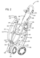
- FIG. 2 shows a perspective view of the stroller frame, minus the seat assembly, of the FIG. 1 in a folded or collapsed configuration.
- FIG. 3 shows a rear perspective view of the stroller frame shown in FIG. 2 and in the unfolded or in-use configuration.
- FIG. 4 shows a front perspective view of the stroller frame shown in FIG. 3 .
- FIGS. 5A-5F show a close up fragmentary view of each of the frame joints on the stroller frame shown in FIGS. 1-5 .
- FIG. 6 is a side view of the stroller frame shown in FIG. 3 .
- FIG. 7 is a cross section of the stroller frame taken along line VII-VII of FIG. 6 .
- FIG. 8 is an enlarged view taken from circle VIII of a portion of the stroller frame cross section shown in FIG. 7 .
- FIGS. 9A and 9B show front and rear perspective views, respectively, of the stroller frame shown in FIG. 3 in a partially folded or collapsed configuration.
- FIGS. 10A, 10B , and 10 C show front and rear perspective views and a side view, respectively, of the stroller frame shown in FIG. 3 in a completely folded or collapsed configuration.
- FIG. 11 shows a cross section of the folded stroller taken along line XI-XI in FIG. 10C .
- FIGS. 12A, 12B , and 12 C show an alternative example of a stroller frame in an in-use, partially folded, and completely collapsed configurations and with the handle remaining in the in-use orientation.
- FIG. 13 shows a perspective enlarged view of the handle assembly for the stroller shown in FIG. 1 in the in-use position and shows the handle in a partly collapsed position in phantom view.
- FIG. 14 shows an enlarged side view of the handle in FIG. 13 in the partly collapsed position.
- FIG. 15 shows a top view of the handle bracket in FIG. 14 .
- FIG. 16 shows a cross section of the handle taken along line XV-XV in FIG. 13 .
- FIG. 17 shows the handle in a further collapsed position and shows the handle assembly in phantom pushed further down onto the stroller frame.
- FIG. 18 shows the handle assembly in its fully collapsed position and shows the handle in phantom prior to being rotated to its fully collapsed position.
- FIG. 19 shows another example of a handle assembly constructed in accordance with the teachings of the present invention.
- the stroller disclosed herein solves or improves upon one or more of the above noted and other problems and disadvantages with known strollers.
- the frame assembly of the disclosed stroller can collapse in three dimensions and yet does not have a traditional box-like frame structure, has a reduced number of components, and folds easily with little effort or maneuvering.
- the disclosed stroller includes a handle assembly that can fold or collapse in to accommodate folding of the stroller.
- the disclosed handle assembly can still provide a variety of different grip locations, orientations, and configurations for a caregiver.
- the stroller 100 is depicted in FIGS. 1-3 and is constructed in accordance with the teachings of the present invention.
- the stroller 100 generally has a frame assembly 102 , a seat assembly 104 supported by the frame assembly, and a plurality of wheels supporting the frame assembly on a ground surface.
- the frame assembly 102 in the disclosed example includes a pair of rear wheels 106 and a single front wheel assembly 108 positioned forward of and at a mid point between the rear wheels.
- the front wheel assembly has two wheels 109 spaced apart side by side.
- the frame assembly 102 in this example generally has a seat mounting frame 110 that is a U-shaped component.
- the seat assembly 104 can be removed from the seat frame 110 and the stroller 100 .
- the removable seat assembly 104 includes a pair of seat attachment tubes 112 positioned on opposite sides of an occupant seat 114 .
- the seat tubes 112 are connected to and can be removed from upper ends 116 of the seat frame 110 .
- the seat 114 of the seat assembly 104 is supported on the stroller at least in part by the seat tubes 112 and has a canopy 118 connected to an upper part of the seat.
- the seat 114 also has a seat back 120 , a seat bottom 122 , and seat side wings 124 positioned on opposite sides of the seat back and the seat bottom.
- a footrest 126 is positioned at the bottom of the seat assembly 104 and is suspended from the front edge of the seat bottom 122 by a mesh fabric panel 128 in this example.
- the footrest 126 is also connected to the lower part of the seat frame 110 .
- the seat 104 can be made entirely of fabric or like materials and be suspended from the seat tubes 112 and the seat frame 110 , when attached.
- portions of the seat assembly 104 can have a removable cover placed over a generally rigid supporting structure that defines and shapes at least part of the seat, such as the seat bottom 122 and parts of the seat side wings 124 .
- the seat assembly 104 can be sufficiently supported on the stroller and substantial enough to support the weight of a child occupant.
- the configuration and construction of the seat assembly 104 and the seat 114 can vary considerably and yet fall within the spirit and scope of the present invention.
- the stroller frame assembly 102 in the disclosed example generally has a central spine 140 with a lower end 142 positioned near the front wheel assembly 108 .
- the spine 140 also has an upper end 144 positioned behind the seat back 120 of the seat assembly 114 and between the rear wheels 106 .
- a pair of curved rear legs 146 extends downward in opposite directions from an underside of the spine 140 . Each leg 146 is bowed outward and extends in a rearward and downward direction.
- a proximal or top end 148 of each leg is coupled to a rear leg connector 150 positioned on the underside of the spine 140 .
- the connector 150 is positioned in this example about mid-point between the upper end 144 and the lower end 142 of the spine 140 .
- a distal or lower end 152 of each rear leg 146 in this example carries one of the rear wheels 106 .
- a rear leg link 154 is positioned on each side of the frame assembly 102 and links each rear leg 146 to the spine 40 .
- Each link 154 has one end 156 coupled to a connector 158 on the underside of the spine 140 positioned below the rear leg connector 150 along the spine.
- Each link 154 also has another end 160 coupled to a corresponding one of the rear legs 146 .
- the links 154 provide stability for the stroller frame assembly 102 , and particularly for the rear legs 146 , during use.
- the frame assembly 102 in the disclosed example also has a stroller handle 170 for pushing and maneuvering the stroller 100 .
- the disclosed handle 170 generally has an upward facing, open C-shape that forms two handle sections 172 .
- the two sections 172 extend in opposite directions from a handle bracket 174 .
- the handle bracket 174 is coupled to a stanchion 176 that extends from the upper end 144 of the frame spine 140 .
- the stanchion 176 is essentially a linear structure and extends parallel to and is aligned with the spine 140 , which is also a generally linear structure.
- the stroller 100 disclosed herein also has a pair of curved seat frame support arms 180 .
- the support arms 180 extend upward in opposite directions from the top side of the spine 140 .
- Each support arm 180 is bowed outward and extends in a forward and upward direction relative to the spine 140 .
- a proximal or bottom end 182 of each support arm 180 is coupled to a support arm connector 184 positioned on the top side of the spine 140 .
- the support arm connector 184 in this example is positioned at the same location along the spine as the rear leg connector 1507 which is on the underside of the spine.
- a distal end portion 186 of each support arm 180 is bent downward, extends generally horizontally forward, and terminates at an exposed end or face 188 .
- a seat frame link 190 is positioned on each side of the seat frame 110 and extends in a rearward direction.
- Each seat link 190 has a free end 192 that is coupled to one of the support arms 180 .
- the connection point between each seat link 190 and the respective support arm 180 in this example is spaced rearward from the exposed end 188 along the distal end portion 186 .
- a frame bracket 194 is located at the lower front portion of the frame assembly 102 .
- the frame bracket 194 is connected to the lower most portion 196 of the seat frame 110 and to the lower end 142 of the spine 140 .
- the front wheel assembly 108 is mounted to and extends downward from the frame bracket 194 .
- the frame bracket 194 links the spine 140 to the seat frame 110 and provides the front wheel mounting location in the disclosed example.
- the spine 140 is oriented centrally between the rear wheels 106 and defines a central or longitudinal axis of the stroller 100 .
- the spine 140 is oriented at an angle with a low point at its lower end 142 and a high point at its upper end 144 .
- the spine is oriented to position the handle 170 so that a caregiver can stand behind the stroller and push the stroller in a conventional manner by the handle 170 .
- the seat assembly 104 is positioned above and forward of the spine 140 and faces forward relative to the stroller 100 away from the handle 170 .
- the arrangement of the seat and frame components disclosed herein can vary and yet fall within the spirit and scope of the present invention. Additionally, the shape, size, configuration, orientation, and location of the various frame assembly and seat assembly components can also vary from the example shown without departing from the spirit and scope of the present invention.
- the above stroller construction can be formed as a fixed structure that cannot be collapsed or folded. Such a stroller configuration would still provide a generally lightweight, easy to maneuver configuration. The stroller would be simpler in construction than an ordinary box-type frame stroller configuration and require fewer components to create the structure.
- the stroller 100 is collapsible or foldable from an in-use configuration shown in FIG. 1 to a folded or collapsed configuration shown in FIG. 2 . As will become apparent below, the stroller 100 is also foldable in three dimensions.
- FIG. 3 shows that the spine 140 is an oval hollow tube in the disclosed example.
- the stanchion 176 is telescopically received in the upper end 144 of the spine 140 and can move lengthwise or longitudinally relative to the spine.
- the rear legs 146 are each coupled to the connector 150 at rotational or pivotal joints 200 and the leg links 154 are also each connected to the link connector 158 at rotational or pivotal joints 202 .
- the other ends 160 of the leg links 154 are each pivotally connected to the respective rear legs 146 at pivot joints 204 .
- the pivot joints 204 are located along the lengths of the rear legs 146 between the ends 148 and 152 of the legs.
- the support arms 180 are also each pivotally connected to the support arm connector 184 at rotational or pivotal joints 206 .
- the free ends 192 of the seat links 190 are pivotally connected to the support arms 180 at pivot joints 208 .
- the pivot joints 208 are spaced from the exposed faces 188 rearward along the distal ends 186 of the support arms.
- the seat frame 110 in this example is formed as three components at its lower portion 196 .
- the seat frame 110 has two upstanding frame posts 197 that curve inward toward one another near the lower portion 196 .
- the bottom ends 198 of the posts are pivotally coupled to a seat frame connector 199 carried on the frame bracket 194 .
- the frame posts 197 are connected at pivotal or rotatable joints 210 to the connector 199 .
- each of the joints 200 , 202 , 204 , 206 , 208 , and 210 noted above is constructed having an angled surface relationship relative to the pivot axis at the joint and the orientation of the components at the joint. The relationship between these elements results in the stroller components simultaneously moving rotationally and laterally inward on the stroller spine 140 during folding.
- abutting bearing surfaces are provided at the joint 200 between the proximal or top end 148 of each rear leg 146 and the rear leg connector 150 .
- Each leg joint 200 has a rotation axis RO and an axis M 0 defined by the orientation of the mating leg 146 and connector 150 .
- An end bearing surface 212 a on each of the rear legs 146 and bearing surface 212 b on the connector 150 abut one another.
- These mating bearing surfaces 212 a , 212 b are oriented so as to lie in a plane that is neither parallel nor perpendicular relative to the axis M 0 of the mating components.
- These surfaces 212 a , 212 b are also oriented generally normal or perpendicular to the rotation axis RO so as to effect or permit rotation of the joint 200 .
- the rotation axis RO offset and the bearing surface 212 a , 212 b incline relative to the component axes M 0 at the joint 200 causes the rear legs 146 , when rotated during folding about the axis RO to both rotate and translate laterally.
- the overall folding function will be described in greater detail below.
- each leg link joint 202 also has a rotation axis R 2 and an axis M 2 defined by the orientation of the mating links 154 and the connector 158 .
- An end bearing surface 214 a on each of the links 154 and a mating bearing surface 214 b on the connector 158 also abut one another. Again, these mating bearing surfaces 214 a and 214 b are oriented to lie in a plane that is neither parallel nor perpendicular to the axis M 2 of the mating components.
- the bearing surfaces 214 a , 214 b are oriented generally perpendicular to the rotation axis R 2 to effect rotation at this joint 202 .
- the arrangement causes the leg links 154 to rotate about the axis R 2 during folding of the stroller as well as to translate laterally.
- each link joint 204 has a rotation axis R 4 and an axis M 4 defined by the orientation of the leg link 154 components and rear leg 146 .
- a bearing surface 216 a is provided on a projection on a side surface of each leg link 154 adjacent the other end 160 .
- a mating bearing surface 216 b is provided on exposed surface of a spacer 218 coupled to each rear leg 146 . The bearing surfaces 216 a of the leg links 154 abut the bearing surfaces 216 b on the spacers.
- These mating bearing surfaces 216 a , 216 b are E oriented so as to lie in a plane that is neither parallel nor perpendicular relative to the axis M 4 of the leg link and the rear leg. These surfaces 216 a , 216 b , are also oriented normal or perpendicular to the rotation axis R 4 to permit rotation at the joint 204 .
- the relationship between the bearing surfaces and the axes at this joint also causes the rear legs 146 and leg links 154 , when rotated during folding about the axis R 4 , to both rotate and translate laterally.
- bearing surfaces are provided at the joint 206 between the proximal ends 182 of each support arm 180 and the arm connector 184 .
- Each support arm joint 206 also has a rotation axis R 6 and an axis M 6 defined by the orientation of the mating support arms 180 and the connector 184 .
- An end bearing surface 220 a on each of the support arms 180 and a bearing surface 220 b on the connector 184 abut one another.
- These mating bearing surfaces 220 a , 220 b are also oriented to lie in a plane that is neither parallel nor perpendicular relative to the axis M 6 of the mating components.
- the surfaces 220 a and 220 b are oriented generally normal or perpendicular to the rotation axis R 6 to effect rotation at the joint 206 .
- the surface and axis relationship at the joint 206 causes the support arms 180 , when rotated during folding about the axis R 6 , to both rotate and translate laterally.
- bearing surfaces are provided at the joint 208 between the distal end portions 186 of the support arms and the seat links 190 .
- Each joint 208 has a rotation axis R 8 and an axis M 8 defined by the orientation of the mating components.
- a bearing surface 222 a is provided on a projection extending from a side of each of the seat links 190 .
- a bearing surface 222 b is provided on an exposed surface of a spacer 224 coupled to the inner side of each support arm 180 .
- These bearing surfaces 222 a , 222 b are also oriented to lie in a plane that is neither parallel nor perpendicular to the axis M 8 of the mating components.
- these surfaces 222 a , 222 b are oriented normal or perpendicular to the rotation axis R 8 to effect rotation of the joint 208 .
- the surface and axis relationship causes the support arms 180 , when rotated during folding about the axis R 8 , to rotate and to translate laterally.
- bearing surfaces are also provided at the joint 210 between the bottom ends 198 of the seat frame posts 197 and the seat frame connector 199 on the frame bracket 194 .
- Each joint 210 has a rotation axis R 10 and an axis M 10 defined by the orientation of the bottom ends 198 of the frame posts 197 and the connector 199 .
- An end bearing surface 226 a is formed on the bottom end 198 of each frame post 199 and a bearing surface 226 b is formed on each side of the connector 199 and these bearing surfaces abut one another.
- the bearing surfaces 226 a , 226 b are oriented so as to lie in a plane neither parallel nor perpendicular to the axis M 10 of these mating components.
- the surfaces 226 a , 226 b are also oriented normal or perpendicular to the rotation axis R 10 to effect rotation at the joint 210 .
- the relationship of the surfaces and axes at the joint 210 causes the seat frame posts 197 , when rotated during folding about the axis R 10 , to rotate and to translate laterally.
- a rack and pinion assembly 230 is provided on the interior of the spine 140 to facilitate smooth component movement as the stroller is folded or unfolded.
- the spine 140 has a telescoping two-part construction with a stationary or base part that we continue to identify herein as the spine 140 .
- the hollow spine also has spine extension 231 that is telescopically received in the bottom opening of the spine base part 140 .
- the exposed end of the spine extension defines the lower end 142 of the spine.
- the spine extension 231 is slidable longitudinally along the spine axis S relative to the base spine part 140 .
- the length of the spine 140 between the upper end 144 and the lower end 142 can be altered during folding.
- the rack and pinion assembly 230 includes a first linear rack 232 secured on the interior of the spine 140 to the slidable spine extension 231 .
- the rack 232 is positioned to one side within the oval interior of the extension and includes a plurality of teeth 234 exposed facing the open side of the spine interior.
- the teeth 234 are conventional gear teeth.
- a secondary rack 236 also of a linear configuration, is carried on the lower end of the stanchion 176 .
- the stanchion 176 longitudinally along the spine axis S can facilitate movement of the second rack 236 and vice versa.
- the stanchion has a C-shape in cross-section with an open side and the rack is installed in the channel of the C-shape.
- the stanchion 176 is also positioned offset to one side of the oval interior of the spine 140 .
- the second rack 236 and the first rack 232 are thus on opposite sides of the oval interior of the spine.
- the rack 236 includes a plurality of gear teeth 238 that face the open side.
- the teeth of the rack 236 are spaced from the teeth of the rack 232 across the interior of the spine 140 in this example and are oriented facing in opposite directions toward one another.
- a stationary pinion 240 is affixed in position on the spine base part 140 and lies within the hollow interior.
- the pinion includes a plurality of gear teeth 242 around its circumference.
- the teeth 242 are sized to mesh with the gear teeth 234 and gear teeth 238 in both of the first and second racks 232 , 236 , respectively.
- the gap between the two racks is such the pinion fits between them and the pinion teeth can engage the teeth of both racks simultaneously.
- the pinion is mounted for free rotation about a gear axis G that is perpendicular to the spine axis S.
- the stroller frame assembly 102 can be folded from the in-use configuration ( FIGS. 3, 4 , 6 , and 7 ) to the folded or collapsed configuration ( FIGS. 2 and 10 A- 11 ).
- the user can push the stanchion 176 via the handle 170 downward into the upper end 144 of the spine 140 .
- the user can grasp and move the leg connector 150 along the spine 140 as discussed below.
- the second rack 236 moves downward passed the pinion 240 . Meshing of the pinion teeth 0 . 242 with the teeth 238 on the second rack 236 causes the pinion 240 to rotate downward on the side of the spine that coincides with the stanchion 176 .
- FIGS. 9A and 9B show the stroller 100 and frame assembly 102 in the partially collapsed configuration. Movement of the stanchion 176 downward and movement of the spine extension 231 upward results in the various stroller frame components beginning to move in concert.
- a slot 250 is provided on the underside of the spine 140 .
- the leg connector 150 includes a coupling 252 that extends through the slot 250 into the interior of the spine 140 .
- the coupling 252 is fixed to and slidable with the first rack 232 and/or the spine extension 231 .
- the top ends 148 of the rear legs 146 which are connector to the connector 150 , move as well.
- the motion of the rear leg joints 200 causes movement at the other joints on the stroller frame assembly 102 .
- the rear wheels 106 pivot or rotate with the rear legs toward the spine 140 , driven by the leg links 154 .
- the leg links 154 are fixed to the underside of the spine 140 at the connector 158 . As the leg connector 150 moves, it moves further from the link connector 158 driving the leg motion.
- the rear legs 146 also move laterally inward toward one another based on the joint 200 geometry.
- the frame bracket 194 is connected to the frame extension 231 and thus moves as the extension slides upward.
- the seat frame 110 is fixed to the bracket 194 .
- the support arms are attached to the arm connector 184 , which is fixed to the top side of the stroller.
- the frame bracket 194 thus moves toward the support arm connector 184 .
- the seat frame 110 including each of the frame posts 197 , also moves upward toward the support arms 180 .
- the seat links 190 are fixed to the frame posts and move with the posts.
- the seat links are pivotally attached at the joints 208 to the arms 180 .
- the seat links 190 drive the ends 186 of the support arms 180 upward, causing them to rotate at the joints 206 on the arm connector 184 on the spine 140 .
- Rotation of the support arms 180 and the joint 208 configuration cause the arms to pivot upward toward the spine 140 and to translate laterally inward toward one another.
- the seat posts 197 are also drawn in, pivoting about the bottom ends 198 at the joints 210 .
- the configuration of the joints 210 also results in the seat frame posts 197 translating laterally inward toward one another.
- FIGS. 10A-10C show the stroller frame assembly 102 upon being fully collapsed.
- the stroller 100 folds or collapses in three dimensions.
- the resulting collapsed frame structure is narrower in width and shorter in height and length when folded than when in the in-use configuration.
- FIG. 11 shows the collapsed positioning of the first and second racks 232 , 236 , the stanchion 176 , the frame extension 231 , and the legs, arms, and connecting components of the structure.
- a user need only pull the stanchion 176 upward and outward out of the frame spine 140 .
- the user can push the connector 150 down along the slot 250 to accomplish unfolding. Either action will in turn drive all of the other components to move to the in-use configuration shown in FIGS. 3, 4 , 6 , and 7 .
- the stanchion 176 and spine extension 231 in the disclosed example are telescoped into the interior of the spine 140 in a side by side relationship and creating a relatively short collapsed height for the frame assembly 102 .
- both the stanchion 176 and spine extension 231 are telescoped outward and extend from the spine 140 .
- the stanchion is offset to one side of the center axis S of the spine, however.
- the spine could be configured with an oval shape but with the taller diameter oriented vertically. This would center the stanchion along the axis S.
- the stroller frame component relationship and positioning can vary.
- the various joint configurations, leg, arm, link, and frame components, and the position of the pivot joints can vary and yet fall within the spirit and scope of the present invention. Changes in geometric shape and component movement can be accomplished by altering the contour of the various frame components. Similarly, the joint locations can be moved from the positions shown in order to accomplish alterations in frame movement and folding configuration as well. Further, the bearing surfaces at the various joints can be altered, the rotation axes changed, and the relative angles between the bearing surfaces and the rotation axes manipulated to alter the in-use frame geometry, the fold motion, and the folded geometry.
- rack and pinion mechanism parts, locations, and configurations can vary as well.
- the rack and pinion mechanism can be replaced with another type of mechanism that will still yield relative movement among the components if one of the components is driven, such as the stanchion 176 or the connector 150 herein.
- the above description does not mention the handle 170 folding from the in-use position to a collapsed position shown in FIGS. 10A-10C .
- the handle 170 can be configured to fold or collapse in concert with the stroller frame assembly 102 . This is generically depicted in the previously noted FIGS. 1-11 .
- the handle 170 can alternatively be configured to fold or collapse independently of the stroller frame assembly 102 . This is depicted generically in FIGS. 12A-12C , which show the stroller frame in the in-use, partially folded, and completely collapsed configurations, respectively. These figures also show the handle 170 remaining in the in-use configuration.
- the handle 170 and its structure and folding arrangements will now be described in greater detail.
- each section 172 of the handle 170 has an outward extending lateral bar part 260 .
- the bar parts 260 extend in opposite directions from opposite sides of the bracket 174 .
- the lateral bar part 260 on each section 172 is not necessarily linear but can be generally linear to form a handle bar configuration. Any part of the lateral bar parts 260 can be gripped by a user.
- Each section 172 also has a curved end part 262 extending from the end of the bar part 260 and curving generally upward.
- Each curved end part 262 has an upward and inward extending grip part 264 .
- the grip parts 264 in the disclosed example generally extend toward one another and are spaced above the linear bar parts 260 .
- the handle bar parts, curved parts, and grip parts provide multiple gripping locations on the handle 170 for a user. As will be evident to those having ordinary skill in the art, the size, shape, and contour of these parts can vary without departing from the spirit and scope of the present invention.
- the disclosed handle 170 can be grasped on virtually any of the parts of each section as desired by a user. Each portion on the handle 170 can provide a different grip angle, grip height, and hand location for the user.
- the handle 170 disclosed herein can be folded by manipulating the handle and the bracket 174 .
- the bracket 174 includes three general components including a stanchion part 266 coupled to the end of the stanchion 176 , an intermediate coupling 268 , and a handle part 270 carried on the handle between the two linear bar parts 260 .
- the intermediate coupling 268 pivotally interconnects the handle part 270 to the stanchion part 266 at two rotational joints (see FIGS. 15, 17 , and 18 ).
- a first joint 272 is formed by a pivot pin or post (not shown) projecting from one end of the coupling 268 and extending into a bore or receptacle (also not shown) in a surface 278 on the stanchion part 266 .
- the surface 278 forms a bearing surface for another surface 280 on the intermediate coupling 268 that forms a complimentary bearing surface.
- the bearing surface 278 on the stanchion part 266 is carried on an ear 282 that projects laterally outward at an angle from one side of the stanchion bracket 266 .
- the ear terminates in the surface 278 .
- the surface lies in a plane that is inclined at an angle of about 45° in the disclosed example relative to the center or spine axis S of the stroller 100 .
- the intermediate coupling 268 can rotate at the joint 272 about the axis H 1 against the surface 278 , and when doing so rotates in a plane that is about 45° off set from the axis of the stroller.
- the other end of the intermediate coupling 268 has a handle connector part 284 oriented at an angle relative to the one end and the bearing surface 280 .
- the connector part 284 in the disclosed example is at an angle of about 45° to the one end of the coupling.
- a handle pin or post 288 projects perpendicularly from a surface of the connector part 284 .
- the handle post 288 extends from the connector part 284 and is thus obliquely angled relative to the bearing surface 280 on the coupling part 268 .
- the handle post 288 when the coupling par 268 is rotated from the in-use orientation to the folded orientation, the handle post 288 also moves from an orientation generally perpendicular or normal to the stroller axis S to an orientation generally parallel to and spaced from the stroller center axis S.
- the handle part 270 of the bracket 174 includes a pair of spaced apart carriage extensions 290 a , 290 b .
- a bore 292 is formed through the extension 290 a .
- the other extension 290 b can have a similar bore or smaller bore (neither being shown) formed therethrough as well that aligns with the bore 292 .
- the handle post 288 in the coupling's L connector part 284 is received through the bore 292 in the carriage extension 290 a .
- the arrangement forms a trunnion-like connection between the handle 170 and the bracket 174 .
- the post can extend to the other extension 290 b for stability if desired.
- a wire pin can extend through the short post 288 in this example, and can extend to a bore in the other extension 290 b .
- This arrangement forms a second joint 291 of the coupling part 268 .
- the handle 170 can pivot about the handle pin 288 about the axis of the aligned bores 292 .
- the handle 170 can pivot from an in-use position where the handle is rotated rearward about the axis H 2 of the bore 292 and post 288 .
- a linear bar part 260 of the handle rests against a curved stop surface 294 formed on an edge of the connector part 284 .
- the stop surface 294 prevents the handle from rotating further and keeps the handle in position when the intermediate coupling 268 is in the in-use position as shown in FIG. 13 .
- Two fingers 295 extend upward from the stanchion part 266 toward the handle 170 .
- a barrel portion 296 of the handle bracket part 270 seats against an end of these fingers 295 .
- the barrel 296 seats against the stop surface 294 and the fingers 295 to provided a stable nesting place for the handle in the in-use configuration.
- the handle 170 does not rotate rearward or downward as it is held in place.
- the handle does not freely rotate forward or upward in the in-use configuration.
- the barrel 296 is firmly sandwiched between the stop surface 294 and the fingers 295 .
- the handle 170 includes two separate release or lock levers as shown in FIG. 13 .
- a safety release lever 300 is positioned on a top side of the bracket 174 and pivots about a point L 1 .
- a latch lever 302 is positioned on the bottom side of the bracket 174 and pivot about a point L 2 .
- a wire catch 304 is pivotally retained on the handle part 270 of the bracket between the pair of carriage extensions 290 and captured between an interior face 306 on the underside of the part 270 and the post 288 .
- a hook 308 protrudes upward from the stanchion part 266 of the bracket and is positioned between the fingers 295 .
- a face on a side of the hook 308 facing away from the catch 304 has a depression configured to mate with the cross-section shape of the wire catch 304 .
- the catch 304 also pivot about the point L 2 and can pivot upward off the hook in the direction of the arrow C and down onto the hook as shown in FIG. 13 .
- An over-center bump 310 on the pivot end of the lever 302 bears against a surface of the barrel 296 and retains the lever in the latched position shown in FIG. 16 .
- the lever also has a turned up end 312 that acts to drive down the catch onto the hook 308 when the lever is raised in the direction of the arrow LL.
- the lever 300 is a latch lever to lock the handle in the in0use position as shown in FIG. 13 .
- the center rib 314 in FIG. 13 adds rigidity to the lever 302 to permit driving the catch downward with sufficient force without bending the lever.
- An underside of the safety latch lever 300 has a release projection 316 that slips into the interior of the bracket 174 when the safety latch lever is pushed or pivoted downward into a latched position as shown in FIG. 13 .
- the protrusion or projection 316 rises and forces the catch upward from the hook 308 .
- the lever 300 is thus a release lever.
- the lever 300 can remain in the ready position when latching the handle, or can rotate forward after the catch 304 is seated in the depression on the hook 308 .
- the protrusion 316 can forcibly bypass the catch to the ready position as shown.
- the release lever 300 is first pulled out to unseat the catch 304 .
- the user can then rotate the handle 170 and the handle part 270 of the bracket downward and sideways, which in turn rotates the intermediate coupling 268 of the bracket about the first joint 272 .
- the handle 170 , bracket part 270 , and coupling part 268 will rotate downward and sideways to the position as shown in FIG. 17 .
- the handle can then be rotated about the handle post 288 inward toward the center axis S of the stroller as shown in FIG. 18 .
- the entire handle 170 can lie very close to the stanchion 176 .
- the stanchion can also be pushed downward into the spine 140 as shown in FIGS. 17 and 18 to completely fold or collapse the remainder of the stroller as described above.
- the handle 170 can fold with the stroller frame or independent of the stroller frame.
- bracket 174 can be modified greatly within the sprit and scope of the present invention. Parts can be reconfigured and rearranged and still function as described. Parts can be modified to a greater extent to create alternative compact handle folds.
- FIG. 19 generically represents a handle assembly 330 with a mounting bracket assembly 332 coupled to the stanchion 176 .
- the bar parts 334 of the handle assembly can pivot directly downward to a position parallel with the spine axis S.
- the bar parts 334 can move in unison so that if one is rotated, the other follow.
- the parts can also be completely independent of one anther if desired.
- Other handle arrangements are also certainly within the spirit and scope of the present invention.
Landscapes
- Engineering & Computer Science (AREA)
- Mechanical Engineering (AREA)
- Chemical & Material Sciences (AREA)
- Combustion & Propulsion (AREA)
- Transportation (AREA)
- Health & Medical Sciences (AREA)
- Public Health (AREA)
- Carriages For Children, Sleds, And Other Hand-Operated Vehicles (AREA)
- Handcart (AREA)
Abstract
Description
- This patent is related to and claims priority benefit of U.S. Provisional Patent Application No. 60/789,240, which was filed on Apr. 3, 2006 and entitled “Stroller,” and which is hereby incorporated by reference in its entirety.
- 1. Field of the Disclosure
- The present invention is generally directed to strollers, and more particularly to a stroller frame structure and stroller handle assembly that are each movable between an in-use configuration and a folded or collapsed configuration.
- 2. Description of Related Art
- Strollers that contact the ground at three general locations, sometimes called “three-wheeled” strollers, are known in the art. This type of stroller is typically a more high-end type stroller and many of these strollers are intended for use during strenuous activity such as jogging or the like. Such strollers typically are either not collapsible or are difficult and cumbersome to collapse or break down to a more portable configuration. These types of three-wheeled strollers also typically have two spaced apart frame sides that converge toward one another near the lone front wheel or wheel assembly. The seat is typically disposed between the frame sides. Thus, this type of stroller is fairly wide and bulky when in the in-use configuration.
- Strollers that fold in three dimensions are also known in the art. There are currently a number of different foldable strollers that are known and that permit folding the stroller and its frame in three dimensions. These stroller configurations have frame links that can fold to allow the stroller to collapse inward or in a width-wise direction. These types of strollers typically incorporate a box-type frame configuration that is also employed in most conventional four-point contact or four-wheeled strollers. Typical three dimensional folding stroller configurations often fold by releasing a centrally located or laterally oriented fold link and then collapsing the stroller frame width-wise, length-wise, and height-wise. Examples include umbrella-type three dimensional folding strollers including Peg Perego's PLAIKO P3 stroller and Graco's CLEO stroller. These fold configurations typically require quite a bit of motion and effort on the part of the user to facilitate folding. Such box type strollers also require a relatively large number of parts and complex fold geometries to permit folding in all three dimensions.
- Virtually every stroller has one or more handles or a handle assembly of some type. The handles are positioned so that the user can manipulate and push the stroller. However, there are very few features built into typical stroller handles that would allow the user to retain better control over the stroller product. Most strollers provide a pair of push arms that curl upward to form an umbrella-type handle on each side of the stroller or have a transverse frame portion that extends across between two frame parts on the stroller to create a handle bar. Strollers that collapse in two dimensions often employ the transverse bar handle configuration because the handle does not need to collapse in a width-wise direction. Strollers that collapse in three dimensions often employ only the umbrella-type handles so that there is no handle bar or link between the two frame sides that need be collapsed. Thus, most strollers provide a very limited number of grip options for the caregiver, and a majority of strollers provide only one grip option.
- Objects, features, and advantages of the present invention will become apparent upon reading the following description in conjunction with the drawing figures, in which:
-
FIG. 1 shows a perspective view of one example of a stroller assembly and a handle assembly in an in-use configuration and constructed in accordance with the teachings of the present invention. -
FIG. 2 shows a perspective view of the stroller frame, minus the seat assembly, of theFIG. 1 in a folded or collapsed configuration. -
FIG. 3 shows a rear perspective view of the stroller frame shown inFIG. 2 and in the unfolded or in-use configuration. -
FIG. 4 shows a front perspective view of the stroller frame shown inFIG. 3 . -
FIGS. 5A-5F show a close up fragmentary view of each of the frame joints on the stroller frame shown inFIGS. 1-5 . -
FIG. 6 is a side view of the stroller frame shown inFIG. 3 . -
FIG. 7 is a cross section of the stroller frame taken along line VII-VII ofFIG. 6 . -
FIG. 8 is an enlarged view taken from circle VIII of a portion of the stroller frame cross section shown inFIG. 7 . -
FIGS. 9A and 9B show front and rear perspective views, respectively, of the stroller frame shown inFIG. 3 in a partially folded or collapsed configuration. -
FIGS. 10A, 10B , and 10C show front and rear perspective views and a side view, respectively, of the stroller frame shown inFIG. 3 in a completely folded or collapsed configuration. -
FIG. 11 shows a cross section of the folded stroller taken along line XI-XI inFIG. 10C . -
FIGS. 12A, 12B , and 12C show an alternative example of a stroller frame in an in-use, partially folded, and completely collapsed configurations and with the handle remaining in the in-use orientation. -
FIG. 13 shows a perspective enlarged view of the handle assembly for the stroller shown inFIG. 1 in the in-use position and shows the handle in a partly collapsed position in phantom view. -
FIG. 14 shows an enlarged side view of the handle inFIG. 13 in the partly collapsed position. -
FIG. 15 shows a top view of the handle bracket inFIG. 14 . -
FIG. 16 shows a cross section of the handle taken along line XV-XV inFIG. 13 . -
FIG. 17 shows the handle in a further collapsed position and shows the handle assembly in phantom pushed further down onto the stroller frame. -
FIG. 18 shows the handle assembly in its fully collapsed position and shows the handle in phantom prior to being rotated to its fully collapsed position. -
FIG. 19 shows another example of a handle assembly constructed in accordance with the teachings of the present invention. - The stroller disclosed herein solves or improves upon one or more of the above noted and other problems and disadvantages with known strollers. For example, the frame assembly of the disclosed stroller can collapse in three dimensions and yet does not have a traditional box-like frame structure, has a reduced number of components, and folds easily with little effort or maneuvering. Also, the disclosed stroller includes a handle assembly that can fold or collapse in to accommodate folding of the stroller. The disclosed handle assembly can still provide a variety of different grip locations, orientations, and configurations for a caregiver. These and other objects, features, and advantages of the present invention will become apparent upon a review of the attached drawing figures and the detailed description below.
- Turning now to the drawings, a
stroller 100 is depicted inFIGS. 1-3 and is constructed in accordance with the teachings of the present invention. In the disclosed example, thestroller 100 generally has aframe assembly 102, aseat assembly 104 supported by the frame assembly, and a plurality of wheels supporting the frame assembly on a ground surface. In general, theframe assembly 102 in the disclosed example includes a pair ofrear wheels 106 and a singlefront wheel assembly 108 positioned forward of and at a mid point between the rear wheels. In this example, the front wheel assembly has twowheels 109 spaced apart side by side. - The
frame assembly 102 in this example generally has aseat mounting frame 110 that is a U-shaped component. In the disclosed example, theseat assembly 104 can be removed from theseat frame 110 and thestroller 100. In general, theremovable seat assembly 104 includes a pair ofseat attachment tubes 112 positioned on opposite sides of anoccupant seat 114. Theseat tubes 112 are connected to and can be removed fromupper ends 116 of theseat frame 110. Theseat 114 of theseat assembly 104 is supported on the stroller at least in part by theseat tubes 112 and has acanopy 118 connected to an upper part of the seat. Theseat 114 also has a seat back 120, aseat bottom 122, andseat side wings 124 positioned on opposite sides of the seat back and the seat bottom. - A
footrest 126 is positioned at the bottom of theseat assembly 104 and is suspended from the front edge of theseat bottom 122 by amesh fabric panel 128 in this example. Thefootrest 126 is also connected to the lower part of theseat frame 110. In the disclosed example, theseat 104 can be made entirely of fabric or like materials and be suspended from theseat tubes 112 and theseat frame 110, when attached. Alternatively, portions of theseat assembly 104 can have a removable cover placed over a generally rigid supporting structure that defines and shapes at least part of the seat, such as theseat bottom 122 and parts of theseat side wings 124. Thus, once attached to theseat frame 110, theseat assembly 104 can be sufficiently supported on the stroller and substantial enough to support the weight of a child occupant. As will be evident to those having ordinary skill in the art, the configuration and construction of theseat assembly 104 and theseat 114 can vary considerably and yet fall within the spirit and scope of the present invention. - The
stroller frame assembly 102 in the disclosed example generally has acentral spine 140 with alower end 142 positioned near thefront wheel assembly 108. Thespine 140 also has anupper end 144 positioned behind the seat back 120 of theseat assembly 114 and between therear wheels 106. A pair of curvedrear legs 146 extends downward in opposite directions from an underside of thespine 140. Eachleg 146 is bowed outward and extends in a rearward and downward direction. A proximal ortop end 148 of each leg is coupled to arear leg connector 150 positioned on the underside of thespine 140. Theconnector 150 is positioned in this example about mid-point between theupper end 144 and thelower end 142 of thespine 140. A distal orlower end 152 of eachrear leg 146 in this example carries one of therear wheels 106. - A
rear leg link 154 is positioned on each side of theframe assembly 102 and links eachrear leg 146 to the spine 40. Eachlink 154 has oneend 156 coupled to aconnector 158 on the underside of thespine 140 positioned below therear leg connector 150 along the spine. Eachlink 154 also has anotherend 160 coupled to a corresponding one of therear legs 146. Thelinks 154 provide stability for thestroller frame assembly 102, and particularly for therear legs 146, during use. - The
frame assembly 102 in the disclosed example also has astroller handle 170 for pushing and maneuvering thestroller 100. The disclosedhandle 170 generally has an upward facing, open C-shape that forms two handlesections 172. The twosections 172 extend in opposite directions from ahandle bracket 174. Thehandle bracket 174 is coupled to astanchion 176 that extends from theupper end 144 of theframe spine 140. In the disclosed example, thestanchion 176 is essentially a linear structure and extends parallel to and is aligned with thespine 140, which is also a generally linear structure. - The
stroller 100 disclosed herein also has a pair of curved seatframe support arms 180. Thesupport arms 180 extend upward in opposite directions from the top side of thespine 140. Eachsupport arm 180 is bowed outward and extends in a forward and upward direction relative to thespine 140. A proximal orbottom end 182 of eachsupport arm 180 is coupled to asupport arm connector 184 positioned on the top side of thespine 140. Thesupport arm connector 184 in this example is positioned at the same location along the spine as the rear leg connector 1507 which is on the underside of the spine. Adistal end portion 186 of eachsupport arm 180 is bent downward, extends generally horizontally forward, and terminates at an exposed end orface 188. - In this example, a
seat frame link 190 is positioned on each side of theseat frame 110 and extends in a rearward direction. Eachseat link 190 has afree end 192 that is coupled to one of thesupport arms 180. The connection point between eachseat link 190 and therespective support arm 180 in this example is spaced rearward from the exposedend 188 along thedistal end portion 186. - Also in the disclosed example, a
frame bracket 194 is located at the lower front portion of theframe assembly 102. Theframe bracket 194 is connected to the lowermost portion 196 of theseat frame 110 and to thelower end 142 of thespine 140. Thefront wheel assembly 108 is mounted to and extends downward from theframe bracket 194. Theframe bracket 194 links thespine 140 to theseat frame 110 and provides the front wheel mounting location in the disclosed example. - The
spine 140 is oriented centrally between therear wheels 106 and defines a central or longitudinal axis of thestroller 100. In the disclosed example as shown inFIG. 2 , thespine 140 is oriented at an angle with a low point at itslower end 142 and a high point at itsupper end 144. The spine is oriented to position thehandle 170 so that a caregiver can stand behind the stroller and push the stroller in a conventional manner by thehandle 170. Theseat assembly 104 is positioned above and forward of thespine 140 and faces forward relative to thestroller 100 away from thehandle 170. However, the arrangement of the seat and frame components disclosed herein can vary and yet fall within the spirit and scope of the present invention. Additionally, the shape, size, configuration, orientation, and location of the various frame assembly and seat assembly components can also vary from the example shown without departing from the spirit and scope of the present invention. - In one example, the above stroller construction can be formed as a fixed structure that cannot be collapsed or folded. Such a stroller configuration would still provide a generally lightweight, easy to maneuver configuration. The stroller would be simpler in construction than an ordinary box-type frame stroller configuration and require fewer components to create the structure. However, in the disclosed example, the
stroller 100 is collapsible or foldable from an in-use configuration shown inFIG. 1 to a folded or collapsed configuration shown inFIG. 2 . As will become apparent below, thestroller 100 is also foldable in three dimensions. - With that in mind,
FIG. 3 shows that thespine 140 is an oval hollow tube in the disclosed example. Thestanchion 176 is telescopically received in theupper end 144 of thespine 140 and can move lengthwise or longitudinally relative to the spine. As depicted inFIGS. 3 and 4 , therear legs 146 are each coupled to theconnector 150 at rotational orpivotal joints 200 and the leg links 154 are also each connected to thelink connector 158 at rotational orpivotal joints 202. The other ends 160 of the leg links 154 are each pivotally connected to the respectiverear legs 146 at pivot joints 204. In the disclosed example, the pivot joints 204 are located along the lengths of therear legs 146 between theends support arms 180 are also each pivotally connected to thesupport arm connector 184 at rotational orpivotal joints 206. The free ends 192 of the seat links 190 are pivotally connected to thesupport arms 180 at pivot joints 208. In the disclosed example, the pivot joints 208 are spaced from the exposed faces 188 rearward along the distal ends 186 of the support arms. - Lastly, the
seat frame 110 in this example is formed as three components at itslower portion 196. Theseat frame 110 has two upstanding frame posts 197 that curve inward toward one another near thelower portion 196. The bottom ends 198 of the posts are pivotally coupled to aseat frame connector 199 carried on theframe bracket 194. The frame posts 197 are connected at pivotal orrotatable joints 210 to theconnector 199. To facilitate three dimensional folding of thestroller 100, each of thejoints stroller spine 140 during folding. - For example, as shown in
FIG. 5A , abutting bearing surfaces are provided at the joint 200 between the proximal ortop end 148 of eachrear leg 146 and therear leg connector 150. Each leg joint 200 has a rotation axis RO and an axis M0 defined by the orientation of themating leg 146 andconnector 150. An end bearing surface 212 a on each of therear legs 146 and bearingsurface 212 b on theconnector 150 abut one another. Thesemating bearing surfaces 212 a, 212 b are oriented so as to lie in a plane that is neither parallel nor perpendicular relative to the axis M0 of the mating components. Thesesurfaces 212 a, 212 b are also oriented generally normal or perpendicular to the rotation axis RO so as to effect or permit rotation of the joint 200. The rotation axis RO offset and thebearing surface 212 a, 212 b incline relative to the component axes M0 at the joint 200 causes therear legs 146, when rotated during folding about the axis RO to both rotate and translate laterally. The overall folding function will be described in greater detail below. - As shown in
FIG. 5B , abutting bearing surfaces are also provided at the joint 202 between the oneend 156 of eachleg link 154 and theleg link connector 158. Each leg link joint 202 also has a rotation axis R2 and an axis M2 defined by the orientation of themating links 154 and theconnector 158. Anend bearing surface 214 a on each of thelinks 154 and amating bearing surface 214 b on theconnector 158 also abut one another. Again, thesemating bearing surfaces - As shown in
FIG. 5C , abutting bearing surfaces are also provided at the joint 204 between theother end 160 of eachleg link 154 and therear leg 146. Each link joint 204 has a rotation axis R4 and an axis M4 defined by the orientation of theleg link 154 components andrear leg 146. A bearingsurface 216 a is provided on a projection on a side surface of eachleg link 154 adjacent theother end 160. Amating bearing surface 216 b is provided on exposed surface of aspacer 218 coupled to eachrear leg 146. The bearing surfaces 216 a of the leg links 154 abut the bearing surfaces 216 b on the spacers. Thesemating bearing surfaces surfaces rear legs 146 andleg links 154, when rotated during folding about the axis R4, to both rotate and translate laterally. - As shown in
FIG. 5D , bearing surfaces are provided at the joint 206 between the proximal ends 182 of eachsupport arm 180 and thearm connector 184. Each support arm joint 206 also has a rotation axis R6 and an axis M6 defined by the orientation of themating support arms 180 and theconnector 184. Anend bearing surface 220 a on each of thesupport arms 180 and abearing surface 220 b on theconnector 184 abut one another. Thesemating bearing surfaces surfaces support arms 180, when rotated during folding about the axis R6, to both rotate and translate laterally. - As shown in
FIG. 5E , bearing surfaces are provided at the joint 208 between thedistal end portions 186 of the support arms and the seat links 190. Each joint 208 has a rotation axis R8 and an axis M8 defined by the orientation of the mating components. A bearingsurface 222 a is provided on a projection extending from a side of each of the seat links 190. A bearingsurface 222 b is provided on an exposed surface of aspacer 224 coupled to the inner side of eachsupport arm 180. These bearingsurfaces surfaces support arms 180, when rotated during folding about the axis R8, to rotate and to translate laterally. - As shown in
FIG. 5F , bearing surfaces are also provided at the joint 210 between the bottom ends 198 of the seat frame posts 197 and theseat frame connector 199 on theframe bracket 194. Each joint 210 has a rotation axis R10 and an axis M10 defined by the orientation of the bottom ends 198 of the frame posts 197 and theconnector 199. Anend bearing surface 226 a is formed on the bottom end 198 of eachframe post 199 and abearing surface 226 b is formed on each side of theconnector 199 and these bearing surfaces abut one another. The bearing surfaces 226 a, 226 b are oriented so as to lie in a plane neither parallel nor perpendicular to the axis M10 of these mating components. Thesurfaces - As shown in
FIGS. 6 and 7 , a rack andpinion assembly 230 is provided on the interior of thespine 140 to facilitate smooth component movement as the stroller is folded or unfolded. In the disclosed example, thespine 140 has a telescoping two-part construction with a stationary or base part that we continue to identify herein as thespine 140. The hollow spine also hasspine extension 231 that is telescopically received in the bottom opening of thespine base part 140. The exposed end of the spine extension defines thelower end 142 of the spine. Thespine extension 231 is slidable longitudinally along the spine axis S relative to thebase spine part 140. Thus, the length of thespine 140 between theupper end 144 and thelower end 142 can be altered during folding. - In the disclosed example, the rack and
pinion assembly 230 includes a firstlinear rack 232 secured on the interior of thespine 140 to theslidable spine extension 231. Thus, movement of thefirst rack 232 can facilitate movement of thespine extension 231 along the spine axis S and vice versa. Therack 232 is positioned to one side within the oval interior of the extension and includes a plurality ofteeth 234 exposed facing the open side of the spine interior. In one example, theteeth 234 are conventional gear teeth. Also as shown inFIG. 7 , asecondary rack 236, also of a linear configuration, is carried on the lower end of thestanchion 176. Thus, movement of thestanchion 176 longitudinally along the spine axis S can facilitate movement of thesecond rack 236 and vice versa. In this example, the stanchion has a C-shape in cross-section with an open side and the rack is installed in the channel of the C-shape. Thestanchion 176 is also positioned offset to one side of the oval interior of thespine 140. Thesecond rack 236 and thefirst rack 232 are thus on opposite sides of the oval interior of the spine. Therack 236 includes a plurality ofgear teeth 238 that face the open side. The teeth of therack 236 are spaced from the teeth of therack 232 across the interior of thespine 140 in this example and are oriented facing in opposite directions toward one another. - A
stationary pinion 240 is affixed in position on thespine base part 140 and lies within the hollow interior. The pinion includes a plurality ofgear teeth 242 around its circumference. Theteeth 242 are sized to mesh with thegear teeth 234 andgear teeth 238 in both of the first andsecond racks - As shown in
FIGS. 2-4 , and 6-11, thestroller frame assembly 102 can be folded from the in-use configuration (FIGS. 3, 4 , 6, and 7) to the folded or collapsed configuration (FIGS. 2 and 10 A-11). The user can push thestanchion 176 via thehandle 170 downward into theupper end 144 of thespine 140. Alternatively, the user can grasp and move theleg connector 150 along thespine 140 as discussed below. By doing either action, thesecond rack 236 moves downward passed thepinion 240. Meshing of the pinion teeth 0.242 with theteeth 238 on thesecond rack 236 causes thepinion 240 to rotate downward on the side of the spine that coincides with thestanchion 176. Theteeth 242 on the opposite side of thepinion 240 are engaged with theteeth 234 on thefirst rack 232, and this side of thepinion 240 rotates upward. Pinion rotation (counterclockwise inFIGS. 7 and 8 ) draws therack 232 and thus thespine extension 231 upward into thespine 140 interior and thestanchion 176 downward. This significantly shortens the height or length of thestroller frame 102. -
FIGS. 9A and 9B show thestroller 100 andframe assembly 102 in the partially collapsed configuration. Movement of thestanchion 176 downward and movement of thespine extension 231 upward results in the various stroller frame components beginning to move in concert. With reference toFIGS. 3, 8 , 9B, and 10B, aslot 250 is provided on the underside of thespine 140. Theleg connector 150 includes acoupling 252 that extends through theslot 250 into the interior of thespine 140. Thecoupling 252 is fixed to and slidable with thefirst rack 232 and/or thespine extension 231. Thus, as theconnector 150 moves upward in the slot along the spine axis S, the top ends 148 of therear legs 146, which are connector to theconnector 150, move as well. The motion of the rear leg joints 200 causes movement at the other joints on thestroller frame assembly 102. Therear wheels 106 pivot or rotate with the rear legs toward thespine 140, driven by the leg links 154. The leg links 154 are fixed to the underside of thespine 140 at theconnector 158. As theleg connector 150 moves, it moves further from thelink connector 158 driving the leg motion. Therear legs 146 also move laterally inward toward one another based on the joint 200 geometry. - As shown in
FIGS. 9A and 9B , theframe bracket 194 is connected to theframe extension 231 and thus moves as the extension slides upward. Theseat frame 110 is fixed to thebracket 194. The support arms are attached to thearm connector 184, which is fixed to the top side of the stroller. As thestroller frame assembly 102 is moved from the in-use configuration to the collapsed configuration, theframe extension 231 and theframe bracket 194 are drawn upward along the spine axis S. Theframe bracket 194 thus moves toward thesupport arm connector 184. As a result, theseat frame 110, including each of the frame posts 197, also moves upward toward thesupport arms 180. The seat links 190 are fixed to the frame posts and move with the posts. The seat links are pivotally attached at thejoints 208 to thearms 180. The seat links 190 drive theends 186 of thesupport arms 180 upward, causing them to rotate at thejoints 206 on thearm connector 184 on thespine 140. Rotation of thesupport arms 180 and the joint 208 configuration cause the arms to pivot upward toward thespine 140 and to translate laterally inward toward one another. As the ends 186 of thesupport arms 180 draw closer to thespine 140, the seat posts 197 are also drawn in, pivoting about the bottom ends 198 at thejoints 210. The configuration of thejoints 210 also results in the seat frame posts 197 translating laterally inward toward one another. -
FIGS. 10A-10C show thestroller frame assembly 102 upon being fully collapsed. As a result of the frame components pivoting toward the spine and translating laterally in ward toward the spine, thestroller 100 folds or collapses in three dimensions. The resulting collapsed frame structure is narrower in width and shorter in height and length when folded than when in the in-use configuration.FIG. 11 shows the collapsed positioning of the first andsecond racks stanchion 176, theframe extension 231, and the legs, arms, and connecting components of the structure. - To unfold the
stroller 100, a user need only pull thestanchion 176 upward and outward out of theframe spine 140. Alternatively, the user can push theconnector 150 down along theslot 250 to accomplish unfolding. Either action will in turn drive all of the other components to move to the in-use configuration shown inFIGS. 3, 4 , 6, and 7. When the stroller is in the collapsed configuration, thestanchion 176 andspine extension 231 in the disclosed example are telescoped into the interior of thespine 140 in a side by side relationship and creating a relatively short collapsed height for theframe assembly 102. In the unfolded configuration, both thestanchion 176 andspine extension 231 are telescoped outward and extend from thespine 140. The stanchion is offset to one side of the center axis S of the spine, however. In an alternate embodiment, the spine could be configured with an oval shape but with the taller diameter oriented vertically. This would center the stanchion along the axis S. - As will be evident to those having ordinary skill in the art, the stroller frame component relationship and positioning can vary. The various joint configurations, leg, arm, link, and frame components, and the position of the pivot joints can vary and yet fall within the spirit and scope of the present invention. Changes in geometric shape and component movement can be accomplished by altering the contour of the various frame components. Similarly, the joint locations can be moved from the positions shown in order to accomplish alterations in frame movement and folding configuration as well. Further, the bearing surfaces at the various joints can be altered, the rotation axes changed, and the relative angles between the bearing surfaces and the rotation axes manipulated to alter the in-use frame geometry, the fold motion, and the folded geometry. Additionally, other component arrangements can be employed with the various moving parts of the spine, stanchion, and frame extension, and yet achieve relative movement of the frame components disclosed and described herein. The rack and pinion mechanism parts, locations, and configurations can vary as well. The rack and pinion mechanism can be replaced with another type of mechanism that will still yield relative movement among the components if one of the components is driven, such as the
stanchion 176 or theconnector 150 herein. - The above description does not mention the
handle 170 folding from the in-use position to a collapsed position shown inFIGS. 10A-10C . Thehandle 170 can be configured to fold or collapse in concert with thestroller frame assembly 102. This is generically depicted in the previously notedFIGS. 1-11 . Thehandle 170 can alternatively be configured to fold or collapse independently of thestroller frame assembly 102. This is depicted generically inFIGS. 12A-12C , which show the stroller frame in the in-use, partially folded, and completely collapsed configurations, respectively. These figures also show thehandle 170 remaining in the in-use configuration. Thehandle 170 and its structure and folding arrangements will now be described in greater detail. - In another aspect of the present invention as shown in
FIGS. 13-18 , thehandle 170 can also be collapsed and folded relative to thestroller 100, and particularly relative to thestanchion 176. In the disclosed example, eachsection 172 of thehandle 170 has an outward extendinglateral bar part 260. Thebar parts 260 extend in opposite directions from opposite sides of thebracket 174. Thelateral bar part 260 on eachsection 172 is not necessarily linear but can be generally linear to form a handle bar configuration. Any part of thelateral bar parts 260 can be gripped by a user. - Each
section 172 also has acurved end part 262 extending from the end of thebar part 260 and curving generally upward. Eachcurved end part 262 has an upward and inward extendinggrip part 264. Thegrip parts 264 in the disclosed example generally extend toward one another and are spaced above thelinear bar parts 260. The handle bar parts, curved parts, and grip parts provide multiple gripping locations on thehandle 170 for a user. As will be evident to those having ordinary skill in the art, the size, shape, and contour of these parts can vary without departing from the spirit and scope of the present invention. The disclosedhandle 170 can be grasped on virtually any of the parts of each section as desired by a user. Each portion on thehandle 170 can provide a different grip angle, grip height, and hand location for the user. - The
handle 170 disclosed herein can be folded by manipulating the handle and thebracket 174. Thebracket 174 includes three general components including astanchion part 266 coupled to the end of thestanchion 176, anintermediate coupling 268, and ahandle part 270 carried on the handle between the twolinear bar parts 260. Theintermediate coupling 268 pivotally interconnects thehandle part 270 to thestanchion part 266 at two rotational joints (seeFIGS. 15, 17 , and 18). A first joint 272 is formed by a pivot pin or post (not shown) projecting from one end of thecoupling 268 and extending into a bore or receptacle (also not shown) in asurface 278 on thestanchion part 266. Thesurface 278 forms a bearing surface for anothersurface 280 on theintermediate coupling 268 that forms a complimentary bearing surface. The bearingsurface 278 on thestanchion part 266 is carried on anear 282 that projects laterally outward at an angle from one side of thestanchion bracket 266. The ear terminates in thesurface 278. The surface lies in a plane that is inclined at an angle of about 45° in the disclosed example relative to the center or spine axis S of thestroller 100. Thus, as shown inFIGS. 13 and 15 , theintermediate coupling 268 can rotate at the joint 272 about the axis H1 against thesurface 278, and when doing so rotates in a plane that is about 45° off set from the axis of the stroller. - As illustrated in
FIGS. 13 and 15 , the other end of theintermediate coupling 268 has a handle connector part 284 oriented at an angle relative to the one end and thebearing surface 280. The connector part 284 in the disclosed example is at an angle of about 45° to the one end of the coupling. Thus, when theintermediate coupling 268 is rotated from an in-use position shown inFIG. 13 in the direction of folding indicated by the arrows to the collapsed position shown inFIG. 17 , the connector part 284 changes in orientation from extending generally vertically upright and parallel to the axis S of the stroller to extending horizontal and generally perpendicular to the axis S. As can be seen inFIG. 14 , a handle pin or post 288 projects perpendicularly from a surface of the connector part 284. Thehandle post 288 extends from the connector part 284 and is thus obliquely angled relative to thebearing surface 280 on thecoupling part 268. Thus, as shown inFIGS. 13-15 and 17, when thecoupling par 268 is rotated from the in-use orientation to the folded orientation, thehandle post 288 also moves from an orientation generally perpendicular or normal to the stroller axis S to an orientation generally parallel to and spaced from the stroller center axis S. - As shown in
FIGS. 14 and 15 , thehandle part 270 of thebracket 174 includes a pair of spaced apartcarriage extensions extension 290 a. Theother extension 290 b can have a similar bore or smaller bore (neither being shown) formed therethrough as well that aligns with the bore 292. Thehandle post 288 in the coupling's L connector part 284 is received through the bore 292 in thecarriage extension 290 a. The arrangement forms a trunnion-like connection between thehandle 170 and thebracket 174. The post can extend to theother extension 290 b for stability if desired. Also, a wire pin can extend through theshort post 288 in this example, and can extend to a bore in theother extension 290 b. This arrangement forms a second joint 291 of thecoupling part 268. - As shown in phantom in
FIG. 18 and by the arrows inFIGS. 14 and 15 , thehandle 170 can pivot about thehandle pin 288 about the axis of the aligned bores 292. Thehandle 170 can pivot from an in-use position where the handle is rotated rearward about the axis H2 of the bore 292 andpost 288. In this position, alinear bar part 260 of the handle rests against a curved stop surface 294 formed on an edge of the connector part 284. The stop surface 294 prevents the handle from rotating further and keeps the handle in position when theintermediate coupling 268 is in the in-use position as shown inFIG. 13 . Twofingers 295 extend upward from thestanchion part 266 toward thehandle 170. Abarrel portion 296 of thehandle bracket part 270 seats against an end of thesefingers 295. Thebarrel 296 seats against the stop surface 294 and thefingers 295 to provided a stable nesting place for the handle in the in-use configuration. During use, thehandle 170 does not rotate rearward or downward as it is held in place. The handle does not freely rotate forward or upward in the in-use configuration. Thebarrel 296 is firmly sandwiched between the stop surface 294 and thefingers 295. - In the disclosed example, the
handle 170 includes two separate release or lock levers as shown inFIG. 13 . Asafety release lever 300 is positioned on a top side of thebracket 174 and pivots about a point L1. Alatch lever 302 is positioned on the bottom side of thebracket 174 and pivot about a point L2. As shown inFIG. 16 , in the assembled bracket 174 awire catch 304 is pivotally retained on thehandle part 270 of the bracket between the pair of carriage extensions 290 and captured between aninterior face 306 on the underside of thepart 270 and thepost 288. Ahook 308 protrudes upward from thestanchion part 266 of the bracket and is positioned between thefingers 295. A face on a side of thehook 308 facing away from thecatch 304 has a depression configured to mate with the cross-section shape of thewire catch 304. Thecatch 304 also pivot about the point L2 and can pivot upward off the hook in the direction of the arrow C and down onto the hook as shown inFIG. 13 . - An
over-center bump 310 on the pivot end of thelever 302 bears against a surface of thebarrel 296 and retains the lever in the latched position shown inFIG. 16 . The lever also has a turned upend 312 that acts to drive down the catch onto thehook 308 when the lever is raised in the direction of the arrow LL. Thus, thelever 300 is a latch lever to lock the handle in the in0use position as shown inFIG. 13 . The center rib 314 inFIG. 13 adds rigidity to thelever 302 to permit driving the catch downward with sufficient force without bending the lever. - An underside of the
safety latch lever 300 has arelease projection 316 that slips into the interior of thebracket 174 when the safety latch lever is pushed or pivoted downward into a latched position as shown inFIG. 13 . When thelever 300 is pivoted out and down in the direction of the arrow L, the protrusion orprojection 316 rises and forces the catch upward from thehook 308. Thelever 300 is thus a release lever. Thelever 300 can remain in the ready position when latching the handle, or can rotate forward after thecatch 304 is seated in the depression on thehook 308. Theprotrusion 316 can forcibly bypass the catch to the ready position as shown. - To collapse the
handle 170 from the in-use position ofFIG. 13 , therelease lever 300 is first pulled out to unseat thecatch 304. The user can then rotate thehandle 170 and thehandle part 270 of the bracket downward and sideways, which in turn rotates theintermediate coupling 268 of the bracket about the first joint 272. Thehandle 170,bracket part 270, andcoupling part 268 will rotate downward and sideways to the position as shown inFIG. 17 . The handle can then be rotated about thehandle post 288 inward toward the center axis S of the stroller as shown inFIG. 18 . Thus, theentire handle 170 can lie very close to thestanchion 176. The stanchion can also be pushed downward into thespine 140 as shown inFIGS. 17 and 18 to completely fold or collapse the remainder of the stroller as described above. As noted above, thehandle 170 can fold with the stroller frame or independent of the stroller frame. - As will be evident to those having ordinary skill in the art, the various components and parts of the
bracket 174 can be modified greatly within the sprit and scope of the present invention. Parts can be reconfigured and rearranged and still function as described. Parts can be modified to a greater extent to create alternative compact handle folds. - For example,
FIG. 19 generically represents ahandle assembly 330 with a mountingbracket assembly 332 coupled to thestanchion 176. In this example, thebar parts 334 of the handle assembly can pivot directly downward to a position parallel with the spine axis S. In one example, thebar parts 334 can move in unison so that if one is rotated, the other follow. The parts can also be completely independent of one anther if desired. Other handle arrangements are also certainly within the spirit and scope of the present invention. - Although certain stroller frame, cup holder, and handle features and examples have been described herein in accordance with the teachings of the present disclosure, the scope of coverage of this patent is not limited thereto. On the contrary, this patent covers all embodiments of the teachings of the disclosure that fairly fall within the scope of permissible equivalents.
Claims (1)
Priority Applications (1)
| Application Number | Priority Date | Filing Date | Title |
|---|---|---|---|
| US11/696,183 US7694980B2 (en) | 2006-04-03 | 2007-04-03 | Handle for collapsible stroller |
Applications Claiming Priority (2)
| Application Number | Priority Date | Filing Date | Title |
|---|---|---|---|
| US78924006P | 2006-04-03 | 2006-04-03 | |
| US11/696,183 US7694980B2 (en) | 2006-04-03 | 2007-04-03 | Handle for collapsible stroller |
Publications (2)
| Publication Number | Publication Date |
|---|---|
| US20070290469A1 true US20070290469A1 (en) | 2007-12-20 |
| US7694980B2 US7694980B2 (en) | 2010-04-13 |
Family
ID=38309970
Family Applications (10)
| Application Number | Title | Priority Date | Filing Date |
|---|---|---|---|
| US11/696,013 Abandoned US20070241524A1 (en) | 2006-04-03 | 2007-04-03 | Stroller with Removable Storage |
| US11/696,084 Abandoned US20070235966A1 (en) | 2006-04-03 | 2007-04-03 | Stroller with Removable Arm Bar |
| US11/696,165 Expired - Fee Related US7543841B2 (en) | 2006-04-03 | 2007-04-03 | Cup holder for a stroller |
| US11/696,158 Abandoned US20080029980A1 (en) | 2006-04-03 | 2007-04-03 | Stroller Seat Recline Mechanism |
| US11/732,720 Expired - Fee Related US8087680B2 (en) | 2006-04-03 | 2007-04-03 | Stroller with car seat attachment |
| US11/696,150 Expired - Fee Related US7735843B2 (en) | 2006-04-03 | 2007-04-03 | Stroller brake system |
| US11/696,183 Expired - Fee Related US7694980B2 (en) | 2006-04-03 | 2007-04-03 | Handle for collapsible stroller |
| US11/696,181 Expired - Fee Related US7909353B2 (en) | 2006-04-03 | 2007-04-03 | Stroller frame having a spine assembly for folding and extending the stroller frame |
| US11/696,167 Expired - Fee Related US7770905B2 (en) | 2006-04-03 | 2007-04-03 | Stroller wheel suspension |
| US11/696,154 Expired - Fee Related US7677590B2 (en) | 2006-04-03 | 2007-04-03 | Stroller having extendable handle |
Family Applications Before (6)
| Application Number | Title | Priority Date | Filing Date |
|---|---|---|---|
| US11/696,013 Abandoned US20070241524A1 (en) | 2006-04-03 | 2007-04-03 | Stroller with Removable Storage |
| US11/696,084 Abandoned US20070235966A1 (en) | 2006-04-03 | 2007-04-03 | Stroller with Removable Arm Bar |
| US11/696,165 Expired - Fee Related US7543841B2 (en) | 2006-04-03 | 2007-04-03 | Cup holder for a stroller |
| US11/696,158 Abandoned US20080029980A1 (en) | 2006-04-03 | 2007-04-03 | Stroller Seat Recline Mechanism |
| US11/732,720 Expired - Fee Related US8087680B2 (en) | 2006-04-03 | 2007-04-03 | Stroller with car seat attachment |
| US11/696,150 Expired - Fee Related US7735843B2 (en) | 2006-04-03 | 2007-04-03 | Stroller brake system |
Family Applications After (3)
| Application Number | Title | Priority Date | Filing Date |
|---|---|---|---|
| US11/696,181 Expired - Fee Related US7909353B2 (en) | 2006-04-03 | 2007-04-03 | Stroller frame having a spine assembly for folding and extending the stroller frame |
| US11/696,167 Expired - Fee Related US7770905B2 (en) | 2006-04-03 | 2007-04-03 | Stroller wheel suspension |
| US11/696,154 Expired - Fee Related US7677590B2 (en) | 2006-04-03 | 2007-04-03 | Stroller having extendable handle |
Country Status (5)
| Country | Link |
|---|---|
| US (10) | US20070241524A1 (en) |
| EP (9) | EP2001709B1 (en) |
| CN (8) | CN101410287B (en) |
| DE (1) | DE602007010435D1 (en) |
| WO (10) | WO2008054853A1 (en) |
Cited By (2)
| Publication number | Priority date | Publication date | Assignee | Title |
|---|---|---|---|---|
| CN107336737A (en) * | 2017-07-17 | 2017-11-10 | 上海童歌母婴用品有限公司 | A kind of three wheeled stroller |
| KR102299925B1 (en) * | 2020-05-18 | 2021-09-09 | 주식회사 파파야나인 | Baby carriage |
Families Citing this family (94)
| Publication number | Priority date | Publication date | Assignee | Title |
|---|---|---|---|---|
| US20070228696A1 (en) * | 2006-03-20 | 2007-10-04 | Graco Children's Products Inc. | Foldable Stroller Having Discrete Handlebar |
| DE202006017674U1 (en) * | 2006-11-17 | 2007-02-22 | Ilinko Ltd. | Hood for e.g. perambulator, has hood units, and main hood surface with radial distance to rotation axis smaller than maximum radial distance of front edge limit, so that one of hood units is retractable by rear edge limit of other hood unit |
| US8215808B2 (en) | 2007-02-19 | 2012-07-10 | Thorley Industries Llc | Lighting system for a stroller |
| AU2008218786B2 (en) | 2007-02-19 | 2013-01-10 | Thorley Industries | Stroller |
| EP1970286A1 (en) * | 2007-03-15 | 2008-09-17 | Team-Tex | Device for transporting a child |
| NL1033729C2 (en) * | 2007-04-20 | 2008-10-21 | Maxi Miliaan Bv | Stroller. |
| DE102007047701A1 (en) * | 2007-10-05 | 2009-04-09 | Viktor Lang | Wheel i.e. perambulator wheel, suspension, has flexible element formed by polymer material and arranged between parts of bearing element and/or between part of bearing element and wheel mounting suspension or chassis |
| CN201151422Y (en) * | 2007-11-13 | 2008-11-19 | 钟志群 | Back wheel steering hand brake perambulator |
| CN101861264B (en) * | 2007-11-16 | 2013-04-03 | 葛莱儿婴儿产品股份有限公司 | Stroller and infant carrier system |
| FR2926521B1 (en) * | 2008-01-17 | 2010-03-19 | Jean Michel Francoi Chaudeurge | PUSHCHAIR CHASSIS, IN PARTICULAR FOR TRANSPORTING A CHILD |
| FR2931432B1 (en) * | 2008-05-22 | 2011-01-07 | Dorel France Sa | FOLDING STROLLER WITH ASSISTED FOLDING BY ROLLING ELEMENTS |
| US8210550B2 (en) * | 2008-06-09 | 2012-07-03 | Orbit Baby, Inc. | Suspension system for baby stroller |
| GB2464087B (en) | 2008-07-02 | 2012-04-25 | Maxi Miliaan Bv | Collapsible support frame |
| US10001804B2 (en) * | 2008-08-11 | 2018-06-19 | Force Dimension S.A.R.L. | Force-feedback device and method |
| GB2468767B (en) * | 2009-03-16 | 2011-07-06 | Graco Childrens Prod Inc | Stroller adapter for an infant car seat |
| US8505958B2 (en) * | 2009-03-25 | 2013-08-13 | Kolcraft Enterprises, Inc. | Sit or stand strollers and methods of making the same |
| US20100313924A1 (en) * | 2009-06-15 | 2010-12-16 | Sang Deog Cho | Walker |
| US8262107B2 (en) * | 2009-09-10 | 2012-09-11 | Nuna International B.V. | Stroller and related vibration-absorbing mechanism |
| CN102039920B (en) * | 2009-10-14 | 2012-11-28 | 明门香港股份有限公司 | Stroller that can be combined with a car seat |
| USD625099S1 (en) * | 2009-11-12 | 2010-10-12 | Karcie Donald L | Collapsible canopy |
| US20110163520A1 (en) * | 2009-11-16 | 2011-07-07 | The Boppy Company, Llc | Stroller liner with toy attachment system |
| CN101734272B (en) * | 2010-01-12 | 2011-11-16 | 好孩子儿童用品有限公司 | Children cart |
| GB201002427D0 (en) * | 2010-02-15 | 2010-03-31 | Clifton Russell A | Multi-purpose wheeled conveyance |
| IL204026A (en) | 2010-02-18 | 2011-01-31 | Lior Ferdman | Wheel speed regulator |
| CN102241255B (en) * | 2010-05-13 | 2013-06-05 | 荷兰商伍轮实业股份有限公司 | Latch device for coupling a carrier to a stroller frame and a stroller frame capable of assembling the carrier |
| CN101898579B (en) * | 2010-07-29 | 2012-11-07 | 好孩子儿童用品有限公司 | Baby carrier |
| DE102010037506A1 (en) * | 2010-09-13 | 2012-03-15 | Greentom Taiwan Manufacturing Ltd. | buggy |
| USD722541S1 (en) | 2010-10-08 | 2015-02-17 | Baby Trend Inc. | Double stroller |
| CN101973304A (en) * | 2010-10-08 | 2011-02-16 | 明门香港股份有限公司 | Baby bearing device and wheel assembly thereof |
| US8646802B2 (en) * | 2010-10-08 | 2014-02-11 | Baby Trend Inc. | Stroller with a receiving frame and support straps for receiving a car seat |
| JP5466683B2 (en) * | 2010-10-08 | 2014-04-09 | 明門香港股▲フェン▼有限公司 | Wheel assembly and stroller for infant carrier |
| US8490243B2 (en) * | 2010-10-08 | 2013-07-23 | Wonderland Nurserygoods Company Limited | Wheel assembly for an infant carrier apparatus |
| US8641077B2 (en) | 2010-10-08 | 2014-02-04 | Baby Trend Inc. | Stroller with a receiving frame and support straps for receiving car seats |
| CN102530046A (en) * | 2010-12-29 | 2012-07-04 | 东莞市寮步齐家日用品设计服务部 | Stroller for easy access |
| US8608190B2 (en) * | 2011-03-08 | 2013-12-17 | Wonderland Nurserygoods Company Limited | Telescoping handle assembly and stroller equipped with the same |
| CN202345738U (en) * | 2011-09-22 | 2012-07-25 | 明门香港股份有限公司 | Children's barrow |
| US20130119626A1 (en) * | 2011-11-16 | 2013-05-16 | Robert E. Haut | Attachment structure and stroller therewith |
| CN103359141B (en) * | 2012-03-28 | 2016-06-01 | 明门香港股份有限公司 | Children's stroller and its frame |
| US9216755B2 (en) | 2012-03-30 | 2015-12-22 | Kolcraft Enterprises, Inc. | Foldable strollers |
| CN202574328U (en) * | 2012-04-20 | 2012-12-05 | 中山市隆成日用制品有限公司 | Stroller Seat Height Adjustment Mechanism |
| US9027434B2 (en) * | 2012-07-16 | 2015-05-12 | Sram, Llc | Two position control device |
| WO2014058986A1 (en) * | 2012-10-09 | 2014-04-17 | Cosco Management, Inc. | Compactible stroller |
| HK1211908A1 (en) | 2012-10-16 | 2016-06-03 | 瑞迪菲勒公司 | Foldable tricycle |
| DE202012104097U1 (en) * | 2012-10-24 | 2012-11-19 | Pius Ponticelli | Device for transporting goods and / or a person |
| CN103072613B (en) * | 2013-01-05 | 2016-02-10 | 好孩子儿童用品有限公司 | Children trolley |
| US10220734B2 (en) | 2013-03-05 | 2019-03-05 | Pidyon Controls Inc. | Car seat |
| US10150389B2 (en) | 2013-03-05 | 2018-12-11 | Pidyon Controls Inc. | Car seat and connection system |
| US9487110B2 (en) | 2014-03-05 | 2016-11-08 | Pidyon Controls Inc. | Car seat |
| US8911015B2 (en) | 2013-03-05 | 2014-12-16 | Yochanan Cohen | Car seat |
| US9254858B2 (en) | 2013-05-21 | 2016-02-09 | Artsana Usa, Inc. | Combination drag and parking brake for a stroller |
| US9108659B2 (en) | 2013-08-07 | 2015-08-18 | Recaro Child Safety Llc | Stroller with selectively hidden adapters |
| US9637153B2 (en) | 2013-09-19 | 2017-05-02 | Kids Ii, Inc. | Child-carrier mounting adapter |
| EP2862473B1 (en) | 2013-10-15 | 2018-08-22 | Samsonite IP Holdings S.a.r.l | Luggage article with a cantilevered wheel bracket having elongated arms |
| CN203601347U (en) * | 2013-11-28 | 2014-05-21 | 欧仕儿童用品(福建)有限公司 | Backrest adjusters and buggies |
| CN205075584U (en) * | 2014-08-26 | 2016-03-09 | 中山市乐瑞婴童用品有限公司 | Castor |
| US9616782B2 (en) | 2014-08-29 | 2017-04-11 | Pidyon Controls Inc. | Car seat vehicle connection system, apparatus, and method |
| GB2529718A (en) * | 2014-09-01 | 2016-03-02 | Stroller Tech Ltd | Handle assembly for a folding perambulator and a folding perambulator incorporating the same |
| US9108658B2 (en) | 2015-01-27 | 2015-08-18 | Halley N. Spencer | Stroller locking mechanism |
| USD777607S1 (en) | 2015-03-06 | 2017-01-31 | Radio Flyer Inc. | Folding tricycle |
| EP3075567A1 (en) | 2015-03-31 | 2016-10-05 | Samsonite IP Holdings S.à.r.l. | Luggage article with loop-shaped wheel bracket |
| US9643525B2 (en) | 2015-04-20 | 2017-05-09 | Inoac Usa, Inc. | Device for holding a container |
| US10336394B2 (en) | 2015-06-02 | 2019-07-02 | Radio Flyer Inc. | Foldable tricycle |
| CN104960385A (en) * | 2015-06-30 | 2015-10-07 | 苏州先锋物流装备科技有限公司 | Balance wheel mechanism with shock-absorbing function |
| US9789893B2 (en) | 2015-09-29 | 2017-10-17 | Radio Flyer Inc. | Stroller tricycle |
| JP6653558B2 (en) * | 2015-11-30 | 2020-02-26 | 株式会社リッチェル | Wheelbarrow |
| DE102016102204A1 (en) * | 2016-02-09 | 2017-08-10 | Thyssenkrupp Ag | Suspension device and fastening device for fastening a machine element |
| USD787378S1 (en) | 2016-02-09 | 2017-05-23 | Radio Flyer Inc. | Stroller tricycle |
| EP4155169B1 (en) * | 2016-05-31 | 2025-02-26 | Thule Sweden AB | Rotating handle dynamic brake |
| USD811090S1 (en) | 2016-06-27 | 2018-02-27 | Samsonite Ip Holdings S.A R.L. | Luggage wheel housing with a wheel |
| US11819102B2 (en) | 2016-06-27 | 2023-11-21 | Samsonite Ip Holdings S.A R.L. | Spinner wheel assembly for a luggage case |
| CN114750817A (en) | 2016-07-27 | 2022-07-15 | 考可拉夫特公司 | Stroller with removable seat and related method |
| WO2018022889A1 (en) | 2016-07-27 | 2018-02-01 | Kolcraft Enterprises, Inc. | Foldable strollers with removable seats and related methods |
| WO2018022895A1 (en) | 2016-07-27 | 2018-02-01 | Kolcraft Enterprises, Inc. | Foldable strollers and related methods |
| US9981679B2 (en) | 2016-09-14 | 2018-05-29 | Smart Trike Mnf Pte Ltd. | Full folding tricycle |
| US10442490B2 (en) | 2016-09-14 | 2019-10-15 | Smart Trike Mnf Pte Ltd. | Full folding tricycle |
| CN106672061B (en) * | 2017-02-14 | 2023-03-14 | 中山市特凯斯婴童用品有限公司 | Children that can commutate promotion receive and close umbrella car |
| CN206528510U (en) * | 2017-03-04 | 2017-09-29 | 东莞市森王婴儿用品有限公司 | A portable stroller for children |
| US10308068B2 (en) * | 2017-05-03 | 2019-06-04 | Snap-On Incorporated | Suspension caster |
| US11173747B2 (en) | 2017-05-04 | 2021-11-16 | Kids2, Inc. | Braking and locking system for caster wheels |
| US11052934B2 (en) | 2017-07-27 | 2021-07-06 | Kolcraft Enterprises, Inc. | Foldable strollers and related methods |
| GB2569089B (en) * | 2017-09-13 | 2022-06-29 | Didofy Ltd | Foldable stroller |
| CN108248669A (en) * | 2018-01-24 | 2018-07-06 | 平湖天林儿童用品有限公司 | Mosquito-proof type carriage for children |
| GB2571092A (en) * | 2018-02-15 | 2019-08-21 | Donna Obrien | A device for infant transport |
| CN109017956A (en) * | 2018-09-18 | 2018-12-18 | 中山市西区青原贸易代理服务部 | Cart frame |
| JP6954666B2 (en) * | 2019-10-04 | 2021-10-27 | コンビ株式会社 | Children's seats, bicycles with children's seats and guards |
| CN113120064B (en) * | 2019-12-30 | 2022-08-09 | 明门(中国)幼童用品有限公司 | Wheel fixing device and baby stroller |
| CN113002678A (en) * | 2019-12-20 | 2021-06-22 | 明门瑞士股份有限公司 | Wheel shock absorber structure and children's carrier |
| CN111391908B (en) * | 2020-01-22 | 2021-09-28 | 好孩子儿童用品有限公司 | Children's barrow |
| CN214028816U (en) * | 2020-06-30 | 2021-08-24 | 明门(中国)幼童用品有限公司 | Storage component and infant carrier thereof |
| CA3205946A1 (en) * | 2020-12-21 | 2022-06-30 | Wonderland Switzerland Ag | Travel system having a child carrier with handle that extends and/or rotates |
| CN112550421B (en) * | 2020-12-26 | 2025-07-18 | 太仓新奇乐婴儿用品有限公司 | Baby stroller capable of automatically switching wheel orientation and brake locking state after reversing |
| US12195072B2 (en) * | 2021-06-07 | 2025-01-14 | Graco Children's Products Inc. | Systems and methods for adding wheels to an infant child seat |
| KR20240152378A (en) * | 2022-02-25 | 2024-10-21 | 콤비 가부시키가이샤 | stroller |
| US11932300B1 (en) * | 2022-09-01 | 2024-03-19 | Krzysztof Michal Jablonski | Rolling folding frame with simultaneously deployable handle and wheelbase |
Citations (36)
| Publication number | Priority date | Publication date | Assignee | Title |
|---|---|---|---|---|
| US613633A (en) * | 1898-11-01 | Adjustable handle-bar | ||
| US3223430A (en) * | 1964-05-11 | 1965-12-14 | Product Engineering Company | Golf cart wheel latching structure |
| US3503276A (en) * | 1968-10-18 | 1970-03-31 | Ariens Co | Lateral extension handle for cultivators |
| US3796439A (en) * | 1972-02-26 | 1974-03-12 | G Perego | Folding baby carriage which can be carried on the arm |
| US3873117A (en) * | 1973-01-24 | 1975-03-25 | Giuseppe Perego | Foldable baby carriage construction |
| US3887208A (en) * | 1974-01-18 | 1975-06-03 | Paul Vidal | Collapsible and portable utility cart |
| US3936069A (en) * | 1974-01-24 | 1976-02-03 | Pietro Giordani | Collapsible baby stroller |
| US4256325A (en) * | 1977-01-13 | 1981-03-17 | Henry Fleischer | Collapsible frames for baby carriers |
| US4448435A (en) * | 1981-02-12 | 1984-05-15 | Hon Corporation International | Foldable and portable vehicle |
| US4448434A (en) * | 1981-12-30 | 1984-05-15 | Anderson Milan B | Collapsible hand truck |
| US4587864A (en) * | 1983-11-04 | 1986-05-13 | Aprica Kassai Kabushikikaisha | Handle height adjusting mechanism for a baby carriage |
| US4813701A (en) * | 1985-05-29 | 1989-03-21 | Societe D'equipement Menager Industriel Et Commercial S.E.M.I.C.O. | Foldable carriage and transport apparatus |
| US5167069A (en) * | 1989-06-02 | 1992-12-01 | Quinn Kathleen H | Razor reach |
| US5249438A (en) * | 1992-08-20 | 1993-10-05 | Systemwide Product | Mobile cooler with retractable wheels and handles |
| US5354089A (en) * | 1993-05-14 | 1994-10-11 | Sohrt Thomas M | Mobile carrier for augmentative communication |
| US5630601A (en) * | 1994-06-20 | 1997-05-20 | Bielefelder Kuchenmaschinen- Und Transportgerate-Fabrik Vom Braucke Gmbh | Two-wheeled trolley with vertical frame and foldable support wheels |
| US5709400A (en) * | 1993-01-20 | 1998-01-20 | Mgb | Folding assembly for the support or transportation of a person |
| US6099022A (en) * | 1998-02-09 | 2000-08-08 | Pring; Dara | Convertible multi-function stroller |
| US6193263B1 (en) * | 1999-07-19 | 2001-02-27 | Wan-Hsin Lin | Seat positioning frame of a stroller |
| US6203054B1 (en) * | 1996-12-19 | 2001-03-20 | Form Design Corporation | Suspension for stroller |
| US6209892B1 (en) * | 1999-12-14 | 2001-04-03 | William Chester Schaaf | Baby stroller apparatus for use in combination with a standard child's car seat |
| US6301749B1 (en) * | 2000-04-11 | 2001-10-16 | Ching Chiuan Chen | Scooter having foldable hand grips |
| US6398233B1 (en) * | 1999-08-16 | 2002-06-04 | Link Treasure Limited | Foldable stroller with separable infant carrier |
| US20020074774A1 (en) * | 2000-12-14 | 2002-06-20 | Davin Hsu | Adjustable handle of umbrella stroller by telescoping and swiveling |
| US20020117826A1 (en) * | 2001-02-27 | 2002-08-29 | Guang-Gwo Lee | Folding collapsible kick scooter |
| US6446990B1 (en) * | 1998-02-26 | 2002-09-10 | Team Tex | Transport vehicle for an infant of low age |
| US20030132614A1 (en) * | 2002-01-16 | 2003-07-17 | Kreamer David Harrison | Flexible handle jogging stroller |
| US20030214107A1 (en) * | 2002-05-16 | 2003-11-20 | Fernandez Jesus Antonio | Room service table handle |
| US20040227329A1 (en) * | 2003-02-17 | 2004-11-18 | Ampafrance | Baby carriage comprising push arms fitted with rotating handles, and corresponding handle |
| US20050173896A1 (en) * | 2004-01-14 | 2005-08-11 | Daniel Kim | Ergonomic telescoping handle assembly for wheeled luggage |
| US20060001226A1 (en) * | 2001-10-22 | 2006-01-05 | Bjorn Refsum | Trolley |
| US20060027984A1 (en) * | 2004-08-09 | 2006-02-09 | Ming-Tai Huang | Adjustable handle assembly for stroller or toy stroller |
| US7011335B2 (en) * | 2004-01-29 | 2006-03-14 | Deven Faye Kight | Adjustable, bi-directional, removable baby stroller handle |
| US20060157945A1 (en) * | 2003-07-03 | 2006-07-20 | Bjorn Refsum | Locking device for a telescopic stem of a trolley |
| US7226059B1 (en) * | 2005-09-09 | 2007-06-05 | Semeka Samuels | Adaptable transport cart for use with strollers and the like |
| US7396038B2 (en) * | 2002-04-16 | 2008-07-08 | Ampafrance | Children's vehicle with a frame with sliding elements without a space therebetween and corresponding chassis |
Family Cites Families (179)
| Publication number | Priority date | Publication date | Assignee | Title |
|---|---|---|---|---|
| BE436168A (en) | ||||
| US522186A (en) * | 1894-07-03 | Traveling-case for bicycles | ||
| DE272827C (en) * | ||||
| GB595877A (en) | 1945-09-08 | 1947-12-19 | Frank Harry Asprey | Improved perambulator brake |
| US1190491A (en) * | 1915-03-08 | 1916-07-11 | Elmer A Watts | Coupling. |
| US1171722A (en) * | 1915-04-03 | 1916-02-15 | Edgar J Hough | Shock-absorber. |
| GB190889A (en) | 1921-12-05 | 1923-01-04 | Barry Simpson | Improvements in or relating to perambulator undercarriages or spring-frames |
| US1577298A (en) * | 1924-12-04 | 1926-03-16 | Roeller Mary Augusta | Article carrier |
| US1745992A (en) * | 1927-04-21 | 1930-02-04 | Bassick Co | Caster |
| US1708906A (en) * | 1927-05-17 | 1929-04-09 | Sparks Harry | Parcel carrier for baby carriages and the like |
| GB327688A (en) | 1929-01-05 | 1930-04-07 | Coop Wholesale | Improvements in invalid chairs, baby carriages, and the like |
| CH174000A (en) | 1934-03-31 | 1934-12-15 | Walleser Eduard | Braking device on strollers. |
| GB449775A (en) | 1935-01-04 | 1936-07-03 | Barry Simpson | Improvements in invalid and juvenile folding cars or chairs and the like |
| US2231401A (en) * | 1939-10-20 | 1941-02-11 | Wayman Henry | Device for roasting or the like |
| CH218242A (en) * | 1940-11-12 | 1941-11-30 | Walther Ernst | Suspension device on prams, sports and market wagons. |
| GB607858A (en) | 1944-05-10 | 1948-09-07 | Solomon Bott | Improvements in or relating to perambulators |
| US2552443A (en) * | 1944-09-12 | 1951-05-08 | Molinari Jeanne | Shoulder bag |
| US2458922A (en) * | 1944-09-27 | 1949-01-11 | Andresen Ella Veil | Caster |
| FR911732A (en) | 1945-01-29 | 1946-07-18 | Independent wheel suspension for vehicles | |
| US2577579A (en) * | 1945-05-05 | 1951-12-04 | Bertie R Hall | Collapsible cart |
| US2414017A (en) * | 1945-09-13 | 1947-01-07 | Donald J Carr | Collapsible golf bag carrier |
| US2588896A (en) * | 1949-04-15 | 1952-03-11 | Thomas George | Folding push chair |
| US2668049A (en) * | 1952-04-16 | 1954-02-02 | Wales Strippit Corp | Spring utilizing a compressible solid |
| US2724429A (en) * | 1952-11-10 | 1955-11-22 | Rilla R Warner | Tray attachment for high chairs |
| US2885223A (en) * | 1956-10-08 | 1959-05-05 | Hoover Co | Telescopic tube coupling with step adjustment means |
| DE1199629B (en) | 1959-02-25 | 1965-08-26 | Osmo Olavi Tapiovaara | Collapsible stroller |
| US2992833A (en) * | 1959-10-22 | 1961-07-18 | George E Hoedinghaus | Oscilloscope or instrument cart-carrier |
| US3178197A (en) * | 1963-03-25 | 1965-04-13 | Boatner Carolyn | Roll along luggage |
| US3197226A (en) * | 1963-12-17 | 1965-07-27 | Atwood E Erlinder | Folding luggage carrier |
| US3446523A (en) * | 1966-10-19 | 1969-05-27 | Coleman Co | Self-locking adjustable tent pole |
| US3494385A (en) * | 1968-03-07 | 1970-02-10 | Thomas J Hanigan | Tieing or wire twisting tool |
| DE1911322A1 (en) * | 1969-03-06 | 1970-09-24 | Daimler Benz Ag | Device for mutual locking of two telescopic tubes which can be moved relative to one another |
| US3861633A (en) * | 1973-09-12 | 1975-01-21 | Ned E Rappleye | Grocery cart hook |
| US3961803A (en) * | 1973-10-15 | 1976-06-08 | Henry Fleischer | Baby holding device |
| GB1394564A (en) * | 1973-12-18 | 1975-05-21 | Wilson Son Ltd Lawrence | Collapsible structure |
| US3955728A (en) * | 1974-05-28 | 1976-05-11 | Jackson W S | Handlebar bag |
| DE2435262A1 (en) * | 1974-06-28 | 1976-01-15 | Eliopoulos Aristides | Child-proof safety plug connector - has spring-loaded cover flap over socket entry and floating contacts pushed by plug against mains contacts |
| FR2327129A1 (en) * | 1975-10-09 | 1977-05-06 | Eurolando | SUPPORT SUCH AS SEAT OR CARRYCOT ADAPTABLE ON STROLLERS OR CHILDREN'S CAR |
| US4084663A (en) * | 1976-08-30 | 1978-04-18 | Frederick Haley | Automatic brake for wheeled carriages |
| JPS5361835A (en) * | 1976-11-16 | 1978-06-02 | Kasai Kk | Collapsible peramulator |
| US4157839A (en) * | 1978-03-17 | 1979-06-12 | Hoff Barbara A | Baby carriage accessory |
| US4191350A (en) * | 1978-05-01 | 1980-03-04 | William Ormond | Storable holder for a container |
| US4186859A (en) * | 1978-07-31 | 1980-02-05 | Frankfort Roberta L | Convertible bag apparatus |
| US4274567A (en) * | 1979-01-02 | 1981-06-23 | Sawyer Patricia F | Shopping cart organizer |
| US4346912A (en) * | 1979-04-12 | 1982-08-31 | Linda Habib | Basket for stroller |
| EP0051995B1 (en) * | 1980-11-10 | 1986-11-26 | Wheel Developments Limited | Spring member |
| US4462138A (en) * | 1981-05-04 | 1984-07-31 | Pemco-Kalamazoo, Inc. | Wheel bracket assembly having a resilient element with progressively increasing resistance |
| JPS60146753A (en) * | 1984-01-11 | 1985-08-02 | アップリカ葛西株式会社 | Locking mechanism for grip bar of baby carriage |
| US4559669A (en) * | 1984-06-07 | 1985-12-24 | Darnell Corporation, Ltd. | Shock resistant caster having pressure plates and centering projections |
| JPS61135858A (en) * | 1984-12-06 | 1986-06-23 | アップリカ葛西株式会社 | Stop device for wheel |
| GB8504925D0 (en) * | 1985-02-26 | 1985-03-27 | Mather G W | Trolley |
| GB2178306A (en) * | 1985-08-02 | 1987-02-11 | Quaker Oats Co | An adjustable back reclining mechanism for a baby stroller |
| US4649595A (en) * | 1985-10-02 | 1987-03-17 | Shepherd Products U.S. Inc. | Resiliently mounted caster having a pivotally mounted inner body member |
| GB8528270D0 (en) | 1985-11-15 | 1985-12-18 | Flanagan J D | Comfort strut |
| US4679806A (en) * | 1986-02-19 | 1987-07-14 | Te-Chin Handicraft Enterprise Co., Ltd. | Arm rest and handrail assembly for baby carriage |
| US4759559A (en) * | 1986-08-08 | 1988-07-26 | Moulton Lee A | Multiple use article carrier |
| CA1313384C (en) * | 1986-08-18 | 1993-02-02 | Yoshiyuki Suzuki | Guard attachment/removal structure in baby carriage |
| US4852778A (en) * | 1986-10-02 | 1989-08-01 | Huffy Corporation | Combination bicycle bag and handbag |
| JPS63155775U (en) * | 1987-03-31 | 1988-10-13 | ||
| US4728018A (en) * | 1987-06-15 | 1988-03-01 | General Motors Corporation | Beverage holder for vehicle |
| US4961522A (en) * | 1987-10-09 | 1990-10-09 | Weber Randi R | Utility travel pack |
| US4815764A (en) * | 1988-02-26 | 1989-03-28 | Carpenter Dianne M | Carrying device for strollers |
| GB2219054A (en) | 1988-05-27 | 1989-11-29 | Brian John Fulcher | Braking device for pushable vehicles |
| JP2536627Y2 (en) * | 1988-09-13 | 1997-05-21 | コンビ 株式会社 | Shopping cart for baby carriage |
| CN2064435U (en) | 1989-01-26 | 1990-10-24 | 高峰 | Braking type ball foot wheel |
| US5060907A (en) * | 1990-01-12 | 1991-10-29 | Unistrut Corporation | Base for an umbrella |
| US5071046A (en) * | 1990-03-09 | 1991-12-10 | Miller Glenn L | Bicycle attached valise |
| JPH0735811Y2 (en) * | 1990-09-17 | 1995-08-16 | コンビ株式会社 | Stroller protection frame mounting structure |
| US5042590A (en) * | 1990-09-20 | 1991-08-27 | Deere & Company | Tapered C-spring for a disk harrow |
| US5103530A (en) * | 1990-09-28 | 1992-04-14 | Century Products Company | Hub and wheel assembly with shock absorber |
| JPH04154477A (en) * | 1990-10-16 | 1992-05-27 | Konbi Kk | Folding mechanism of stroller |
| US5125676A (en) * | 1991-07-03 | 1992-06-30 | Teng Jerry M S | Controlling structure for a handle and castors of a stroller |
| US5645204A (en) * | 1991-08-21 | 1997-07-08 | Struzer; Cheryl Renee | Encasement enclosed portable attachable/detachable entertainment unit:"The Box" |
| US5203579A (en) * | 1991-10-03 | 1993-04-20 | Sarah Lipschitz | Shop E Z cart |
| US5221066A (en) * | 1991-12-02 | 1993-06-22 | Ferrigan Paul J | Collapsible rack for automotive body panel |
| US5326175A (en) * | 1992-04-13 | 1994-07-05 | Carter James E | Debris/storage bag |
| US5460399A (en) * | 1992-09-18 | 1995-10-24 | Racing Strollers, Inc. | Baby stroller with park brake |
| US5215320A (en) * | 1992-10-14 | 1993-06-01 | Kiddyco Juvenile Products Corporation | Stroller |
| US5388853A (en) * | 1993-04-06 | 1995-02-14 | Kolcraft Enterprises, Inc. | Lock mechanism for a collapsible stroller |
| JP2598239Y2 (en) * | 1993-09-30 | 1999-08-03 | コンビ 株式会社 | Baby stroller protective frame |
| US6189914B1 (en) * | 1993-10-01 | 2001-02-20 | Worth Pfaff Innovations, Inc. | Folding stroller |
| US5370408A (en) * | 1993-11-26 | 1994-12-06 | Eagan; Chris S. | Baby stroller or baby carriage brake systems |
| US5351364A (en) * | 1993-12-21 | 1994-10-04 | Zun Hong Fu | Caster-supporting device for a stroller |
| JPH07300073A (en) * | 1994-05-02 | 1995-11-14 | Masami Mukai | Cup holder and baby carriage provided therewith |
| DE4416737C2 (en) | 1994-05-11 | 1996-08-29 | Juergen Griesbach | Additional handle for strollers |
| US5514152A (en) * | 1994-08-16 | 1996-05-07 | Specialized Health Products, Inc. | Multiple segment encapsulated medical lancing device |
| US5522527A (en) * | 1994-11-09 | 1996-06-04 | Tsai; Richard | Beverage container fixing device for bicycle |
| US5678842A (en) * | 1994-12-23 | 1997-10-21 | Go Industries Inc. | Collapsible cart |
| US5575403A (en) * | 1995-01-13 | 1996-11-19 | Bayer Corporation | Dispensing instrument for fluid monitoring sensors |
| US5622376A (en) * | 1995-02-27 | 1997-04-22 | Shamie; Louis | Stroller with folding mechanism for compact collapsing arrangement |
| US5669625A (en) * | 1995-03-29 | 1997-09-23 | Jane, S.A. | Folding child's pushchair |
| GB2299552B (en) * | 1995-04-03 | 1998-11-18 | Dennis Michael Hislop | Storage container for pull-type golf carts |
| US5618018A (en) * | 1995-06-07 | 1997-04-08 | Manchester Plastics | Cup holder for confined spaces |
| US5581843A (en) * | 1995-08-14 | 1996-12-10 | Purnell; Peter F. | Wheel assembly for baby stroller |
| US5549311A (en) * | 1995-08-29 | 1996-08-27 | Huang; Li-Chu C. | Armrest and handle assembly for a stroller |
| US5772279A (en) * | 1995-08-31 | 1998-06-30 | Kolcraft Enterprises, Inc. | Coupling system for infant carrier to second support device |
| US5676386A (en) * | 1995-10-30 | 1997-10-14 | Huang; Li-Chu Chen | Stroller in combination with a safety seat assembly |
| ES1033012Y (en) * | 1996-01-16 | 1996-12-01 | Jane Sa | TWO-SEAT CHILDREN'S CAR-CHAIR. |
| US5725351A (en) * | 1996-06-18 | 1998-03-10 | Guibert; Chris P. | Golf accessory bag for golf pull carts |
| GB9621453D0 (en) | 1996-10-15 | 1996-12-04 | Mills Christopher J | Suspension assembly for wheeled conveyance |
| US5899915A (en) * | 1996-12-02 | 1999-05-04 | Angiotrax, Inc. | Apparatus and method for intraoperatively performing surgery |
| US5934757A (en) * | 1996-12-27 | 1999-08-10 | Smith; Louis E. | Adjustable flexible seat |
| GB2326395A (en) * | 1997-06-21 | 1998-12-23 | Rover Group | A container holder for a motor vehicle |
| US5845888A (en) * | 1997-07-17 | 1998-12-08 | Prince Corporation | Retractable container holder |
| US5967535A (en) * | 1997-08-14 | 1999-10-19 | Graco Children's Products Inc. | Swivel wheel mount |
| GB9718676D0 (en) * | 1997-09-04 | 1997-11-05 | Maclaren Ltd | Infant carraige |
| US5927441A (en) * | 1997-09-23 | 1999-07-27 | Luo; Chung-I | Braking device for trolley |
| US5864921A (en) * | 1997-12-10 | 1999-02-02 | Chou; Cheng-Tsan | Extensible handle assembly |
| US6059301A (en) * | 1998-01-06 | 2000-05-09 | Skarnulis; Cynthia L. | Baby carriage and adapter handle therefor |
| US6050592A (en) * | 1998-03-23 | 2000-04-18 | Kim; Hyung Ho | Combined golf bag and collapsible golf cart |
| AUPP290298A0 (en) * | 1998-04-09 | 1998-05-07 | Life Therapeutics Limited | Improved electrophoresis gel and gel-forming apparatus |
| GB2346853A (en) * | 1998-07-31 | 2000-08-23 | Ferno Washington | A stair chair |
| JP2000085672A (en) * | 1998-09-11 | 2000-03-28 | Matsushita Electric Ind Co Ltd | Bicycle handle post |
| CN2344253Y (en) * | 1998-09-18 | 1999-10-20 | 何家鑫 | Portable-type pushchair |
| GB2343840A (en) * | 1999-02-05 | 2000-05-24 | Britax Excelsior | Perambulator adaptor for child safety seat |
| US6170615B1 (en) * | 1999-03-29 | 2001-01-09 | Hui-Fen Cheng | Braking device of a three wheel baby car |
| DE29907287U1 (en) | 1999-04-24 | 1999-07-15 | Bischoff & Bischoff & Co. Medizin- und Rehabilitationstechnik Vertriebs- GmbH, 76327 Pfinztal | Twist grip brake device |
| US6152340A (en) * | 1999-06-01 | 2000-11-28 | Link Treasure Limited | Fast demountable structure for carrier basket of stroller |
| NL1012334C2 (en) * | 1999-06-15 | 2000-12-18 | Maxi Miliaan Bv | Stroller. |
| US6212733B1 (en) * | 1999-08-16 | 2001-04-10 | Link Treasure Limited | Hub and wheel assembly with automatic moving direction adjustment mechanism |
| DE29914681U1 (en) * | 1999-08-21 | 2000-12-28 | Tente-Rollen GmbH & Co, 42929 Wermelskirchen | Swivel castor |
| JP4435956B2 (en) * | 1999-09-21 | 2010-03-24 | カヤバ工業株式会社 | caster |
| US6267404B1 (en) * | 1999-10-13 | 2001-07-31 | Link Treasure Limited | Detachable arm structure for a baby stroller |
| US6706159B2 (en) * | 2000-03-02 | 2004-03-16 | Diabetes Diagnostics | Combined lancet and electrochemical analyte-testing apparatus |
| CA2329801A1 (en) * | 2000-05-08 | 2001-11-08 | Graco Children's Products Inc. | Stroller |
| US6539578B1 (en) * | 2000-06-15 | 2003-04-01 | Algood Casters Limited | Deflecting spring caster |
| US6317923B1 (en) * | 2000-06-22 | 2001-11-20 | Albert Chong-Jen Lo | Handle middle tube and a vertical tube containing device for skate-scooters |
| BR8001322Y1 (en) * | 2000-06-23 | 2009-05-05 | set to replace the rear metal axle of toy tricycles. | |
| DE20011258U1 (en) | 2000-06-27 | 2000-09-07 | Tamm, Jens, Dipl.-Ing., 38114 Braunschweig | Children's cart |
| US6305698B1 (en) * | 2000-07-14 | 2001-10-23 | Shan-Kwai Liang | Skating scooter |
| GB0022104D0 (en) * | 2000-09-08 | 2000-10-25 | Crisp David | Collapsible pushchair/carrier |
| US6423014B1 (en) * | 2000-09-29 | 2002-07-23 | University Of Vermont | Therapeutic and diagnostic needling device and method |
| TW491214U (en) * | 2000-12-12 | 2002-06-11 | Pei-Shiou Huang | Improved shelf for soft drinks |
| US20020093160A1 (en) * | 2001-01-12 | 2002-07-18 | Andrew Mendenhall | Juvenile stroller with portable cooler |
| US6439596B1 (en) * | 2001-01-24 | 2002-08-27 | James Tsai | Collapsible handcart |
| GB2373769A (en) * | 2001-03-30 | 2002-10-02 | Far Great Plastics Ind Co Ltd | Bicycle with foldable steering mechanism |
| CN1378937A (en) * | 2001-04-06 | 2002-11-13 | 好孩子儿童用品有限公司 | Umbrella-type pram with front and back seats |
| US6976686B2 (en) * | 2001-04-27 | 2005-12-20 | Hsia Ben M | Detachable front guider arrangement of stroller |
| US6499184B2 (en) * | 2001-05-14 | 2002-12-31 | Ross Design & Engineering, Inc. | Elastomeric biased caster |
| US7025774B2 (en) * | 2001-06-12 | 2006-04-11 | Pelikan Technologies, Inc. | Tissue penetration device |
| US6478503B1 (en) * | 2001-06-26 | 2002-11-12 | Pao-Hsien Cheng | Locking device for a detachable handrest of a stroller |
| CN2493479Y (en) * | 2001-07-18 | 2002-05-29 | 宋军 | Perambulator |
| NL1018642C2 (en) * | 2001-07-26 | 2002-05-14 | Quint B V | Convertible vehicle, particularly for transport of small children, has supporting frame for first holder, such as small child seat, and coupling device connecting seat to frame, together with two axles around which wheels rotate |
| US6478104B1 (en) * | 2001-07-27 | 2002-11-12 | Joseph C. Kemper | Collapsible motor driven vehicle |
| JP4650658B2 (en) * | 2001-09-20 | 2011-03-16 | 株式会社フォルム | Reclining device for stroller |
| GB2379911B (en) * | 2001-09-25 | 2003-09-10 | Red Lan | Seat device for a stroller |
| JP2003095114A (en) * | 2001-09-26 | 2003-04-03 | Combi Corp | Guard arm and stroller with beverage stand |
| US6561537B1 (en) * | 2001-11-16 | 2003-05-13 | Chin-Chiao Chen | Stroller with a resistance providing unit |
| JP3614814B2 (en) | 2001-12-03 | 2005-01-26 | 株式会社幸和製作所 | Wheelbarrow |
| DE10206785A1 (en) | 2002-02-19 | 2003-10-30 | Putz Franz Josef | Automatic brake and wheel lock, at a baby carriage or trolley, has a brake cylinder with a spring-loaded bolt to lock the wheel, to be released by a bar at the handle through a pull cable |
| US6748821B1 (en) * | 2002-02-28 | 2004-06-15 | John C. Smith | Extendable handle bar assembly |
| FR2837160B1 (en) | 2002-03-15 | 2004-07-16 | Amanda Josephine Mari Romefort | FOLDABLE CAR FOR THE TRANSPORT OF CHILDREN WITH TELESCOPIC STRUCTURE |
| GB2403899A (en) | 2002-05-06 | 2005-01-19 | Link Treasure Ltd | Turn-fixing mechanism for stroller wheels |
| US6935652B2 (en) * | 2002-11-19 | 2005-08-30 | Evenflo Company, Inc. | Tandem stroller with side entry and associated fold actuator |
| US6923466B2 (en) * | 2002-12-17 | 2005-08-02 | James Tsai | Collapsible handcart capable of extending the area of carrier by operating handle |
| FR2850073B1 (en) * | 2003-01-17 | 2006-03-17 | Gh Solutions | DEPLOYABLE SEAT |
| BR8303281Y1 (en) | 2003-01-24 | 2012-12-25 | support for attaching to a frame and module such as a baby seat. | |
| US6817451B1 (en) * | 2003-04-02 | 2004-11-16 | Hung-Tsun Chen | Brake system for a running stroller |
| CA105408S (en) | 2003-07-03 | 2005-08-12 | Stokke Gruppen As | Trolley |
| DE20320208U1 (en) | 2003-07-03 | 2004-04-01 | Stokke Gruppen As | Handle for trolley or pram has connector member fitting onto central shaft of pram to allow rotation of handle relative to shaft |
| GB2403934B (en) * | 2003-07-17 | 2006-10-04 | Simon Antonio Goldenberg | A handle arrangement for a pushchair |
| CN100345702C (en) * | 2003-11-10 | 2007-10-31 | 好孩子儿童用品有限公司 | Electric cycle for children |
| JP2005143820A (en) * | 2003-11-14 | 2005-06-09 | Aprica Kassai Inc | Tote bag and baby carriage |
| US20050168023A1 (en) * | 2003-12-01 | 2005-08-04 | Graco Children's Products Inc. | One-hand fold handle for infant carrier |
| US20050140105A1 (en) * | 2003-12-30 | 2005-06-30 | Encuenta Designs, L.L.C. | Jog stroller with steerable front wheel |
| US7118116B2 (en) * | 2004-01-30 | 2006-10-10 | Wang-Hsing Lin | Stroller having front wheels that can be turned stably and smoothly |
| JP2005271647A (en) * | 2004-03-23 | 2005-10-06 | Combi Corp | stroller |
| CA2562786A1 (en) * | 2004-04-30 | 2005-11-17 | Pdp Compass, Llc | Foldable stroller |
| US20050242548A1 (en) | 2004-04-30 | 2005-11-03 | Hutchinson James M F | Easy folding stroller |
| US7234722B1 (en) * | 2004-07-02 | 2007-06-26 | Stroller Technologies, Llc | Standing baby stroller |
| US7213818B2 (en) * | 2004-08-24 | 2007-05-08 | Abmex Enterprise Co., Ltd. | Stroller having wheel rotation control device |
| US7891687B2 (en) * | 2004-12-10 | 2011-02-22 | Magna Marque International Inc. | Method to conceal bicycle control cables within the handlebars, stem and frame |
| JP4360683B2 (en) * | 2004-12-27 | 2009-11-11 | ピジョン株式会社 | stroller |
| CN2787534Y (en) * | 2005-02-02 | 2006-06-14 | 蓝贯仁 | Baby stroller with carrier attachment |
| FR2882015B1 (en) * | 2005-02-16 | 2008-09-26 | Dorel France Sa | STROLLER FOR CHILD, FOLDING UMBRELLA |
| PT1741614E (en) | 2005-07-07 | 2010-09-02 | Jane Sa | A foldable chassis for baby carriages |
| NL1031213C2 (en) * | 2006-02-22 | 2007-08-24 | Maxi Miliaan Bv | Stroller. |
| US20070228696A1 (en) * | 2006-03-20 | 2007-10-04 | Graco Children's Products Inc. | Foldable Stroller Having Discrete Handlebar |
| AU2008218786B2 (en) * | 2007-02-19 | 2013-01-10 | Thorley Industries | Stroller |
-
2007
- 2007-04-03 US US11/696,013 patent/US20070241524A1/en not_active Abandoned
- 2007-04-03 WO PCT/US2007/065898 patent/WO2008054853A1/en active Application Filing
- 2007-04-03 CN CN200780010865.4A patent/CN101410287B/en not_active Expired - Fee Related
- 2007-04-03 CN CN200780010855.0A patent/CN101563266B/en not_active Expired - Fee Related
- 2007-04-03 CN CN200780017377.6A patent/CN101443224B/en not_active Expired - Fee Related
- 2007-04-03 US US11/696,084 patent/US20070235966A1/en not_active Abandoned
- 2007-04-03 WO PCT/US2007/065889 patent/WO2007118098A2/en active Application Filing
- 2007-04-03 WO PCT/US2007/065900 patent/WO2007118102A1/en active Application Filing
- 2007-04-03 CN CN200780009512.2A patent/CN101541590B/en not_active Expired - Fee Related
- 2007-04-03 EP EP07868215A patent/EP2001709B1/en not_active Not-in-force
- 2007-04-03 EP EP07760054A patent/EP2004425A1/en not_active Withdrawn
- 2007-04-03 US US11/696,165 patent/US7543841B2/en not_active Expired - Fee Related
- 2007-04-03 US US11/696,158 patent/US20080029980A1/en not_active Abandoned
- 2007-04-03 US US11/732,720 patent/US8087680B2/en not_active Expired - Fee Related
- 2007-04-03 CN CN200780017356.4A patent/CN101443201B/en not_active Expired - Fee Related
- 2007-04-03 WO PCT/US2007/065901 patent/WO2007118103A1/en active Application Filing
- 2007-04-03 US US11/696,150 patent/US7735843B2/en not_active Expired - Fee Related
- 2007-04-03 EP EP07868213A patent/EP2001726A1/en not_active Withdrawn
- 2007-04-03 EP EP07760055A patent/EP2007614A1/en not_active Withdrawn
- 2007-04-03 EP EP07760050A patent/EP2001728A2/en not_active Withdrawn
- 2007-04-03 EP EP07868214A patent/EP2001723A1/en not_active Withdrawn
- 2007-04-03 US US11/696,183 patent/US7694980B2/en not_active Expired - Fee Related
- 2007-04-03 EP EP07872207A patent/EP2001725A1/en not_active Withdrawn
- 2007-04-03 CN CN200780017466.0A patent/CN101443223A/en active Pending
- 2007-04-03 WO PCT/US2007/065893 patent/WO2008079423A1/en active Application Filing
- 2007-04-03 WO PCT/US2007/065894 patent/WO2008054851A1/en active Application Filing
- 2007-04-03 US US11/696,181 patent/US7909353B2/en not_active Expired - Fee Related
- 2007-04-03 WO PCT/US2007/065877 patent/WO2007118088A2/en active Application Filing
- 2007-04-03 WO PCT/US2007/065897 patent/WO2008054852A1/en active Application Filing
- 2007-04-03 EP EP07754867A patent/EP2001727A2/en not_active Withdrawn
- 2007-04-03 WO PCT/US2007/065895 patent/WO2008085531A1/en active Application Filing
- 2007-04-03 DE DE602007010435T patent/DE602007010435D1/en active Active
- 2007-04-03 US US11/696,167 patent/US7770905B2/en not_active Expired - Fee Related
- 2007-04-03 US US11/696,154 patent/US7677590B2/en not_active Expired - Fee Related
- 2007-04-03 EP EP07760038A patent/EP2004471A2/en not_active Withdrawn
- 2007-04-03 WO PCT/US2007/008420 patent/WO2007117517A2/en active Application Filing
- 2007-04-03 CN CN200780008660.2A patent/CN101400561B/en not_active Expired - Fee Related
- 2007-04-03 CN CN200780018516.7A patent/CN101448695B/en not_active Expired - Fee Related
Patent Citations (39)
| Publication number | Priority date | Publication date | Assignee | Title |
|---|---|---|---|---|
| US613633A (en) * | 1898-11-01 | Adjustable handle-bar | ||
| US3223430A (en) * | 1964-05-11 | 1965-12-14 | Product Engineering Company | Golf cart wheel latching structure |
| US3503276A (en) * | 1968-10-18 | 1970-03-31 | Ariens Co | Lateral extension handle for cultivators |
| US3796439A (en) * | 1972-02-26 | 1974-03-12 | G Perego | Folding baby carriage which can be carried on the arm |
| US3873117A (en) * | 1973-01-24 | 1975-03-25 | Giuseppe Perego | Foldable baby carriage construction |
| US3887208A (en) * | 1974-01-18 | 1975-06-03 | Paul Vidal | Collapsible and portable utility cart |
| US3936069A (en) * | 1974-01-24 | 1976-02-03 | Pietro Giordani | Collapsible baby stroller |
| US4256325A (en) * | 1977-01-13 | 1981-03-17 | Henry Fleischer | Collapsible frames for baby carriers |
| US4448435A (en) * | 1981-02-12 | 1984-05-15 | Hon Corporation International | Foldable and portable vehicle |
| US4448434A (en) * | 1981-12-30 | 1984-05-15 | Anderson Milan B | Collapsible hand truck |
| US4587864A (en) * | 1983-11-04 | 1986-05-13 | Aprica Kassai Kabushikikaisha | Handle height adjusting mechanism for a baby carriage |
| US4813701A (en) * | 1985-05-29 | 1989-03-21 | Societe D'equipement Menager Industriel Et Commercial S.E.M.I.C.O. | Foldable carriage and transport apparatus |
| US5167069A (en) * | 1989-06-02 | 1992-12-01 | Quinn Kathleen H | Razor reach |
| US5249438A (en) * | 1992-08-20 | 1993-10-05 | Systemwide Product | Mobile cooler with retractable wheels and handles |
| US5709400A (en) * | 1993-01-20 | 1998-01-20 | Mgb | Folding assembly for the support or transportation of a person |
| US5354089A (en) * | 1993-05-14 | 1994-10-11 | Sohrt Thomas M | Mobile carrier for augmentative communication |
| US5630601A (en) * | 1994-06-20 | 1997-05-20 | Bielefelder Kuchenmaschinen- Und Transportgerate-Fabrik Vom Braucke Gmbh | Two-wheeled trolley with vertical frame and foldable support wheels |
| US6203054B1 (en) * | 1996-12-19 | 2001-03-20 | Form Design Corporation | Suspension for stroller |
| US6099022A (en) * | 1998-02-09 | 2000-08-08 | Pring; Dara | Convertible multi-function stroller |
| US6446990B1 (en) * | 1998-02-26 | 2002-09-10 | Team Tex | Transport vehicle for an infant of low age |
| US6193263B1 (en) * | 1999-07-19 | 2001-02-27 | Wan-Hsin Lin | Seat positioning frame of a stroller |
| US6398233B1 (en) * | 1999-08-16 | 2002-06-04 | Link Treasure Limited | Foldable stroller with separable infant carrier |
| US6209892B1 (en) * | 1999-12-14 | 2001-04-03 | William Chester Schaaf | Baby stroller apparatus for use in combination with a standard child's car seat |
| US6301749B1 (en) * | 2000-04-11 | 2001-10-16 | Ching Chiuan Chen | Scooter having foldable hand grips |
| US20020074774A1 (en) * | 2000-12-14 | 2002-06-20 | Davin Hsu | Adjustable handle of umbrella stroller by telescoping and swiveling |
| US20020117826A1 (en) * | 2001-02-27 | 2002-08-29 | Guang-Gwo Lee | Folding collapsible kick scooter |
| US20060001226A1 (en) * | 2001-10-22 | 2006-01-05 | Bjorn Refsum | Trolley |
| US20030132614A1 (en) * | 2002-01-16 | 2003-07-17 | Kreamer David Harrison | Flexible handle jogging stroller |
| US7396038B2 (en) * | 2002-04-16 | 2008-07-08 | Ampafrance | Children's vehicle with a frame with sliding elements without a space therebetween and corresponding chassis |
| US20030214107A1 (en) * | 2002-05-16 | 2003-11-20 | Fernandez Jesus Antonio | Room service table handle |
| US20040227329A1 (en) * | 2003-02-17 | 2004-11-18 | Ampafrance | Baby carriage comprising push arms fitted with rotating handles, and corresponding handle |
| US20060157945A1 (en) * | 2003-07-03 | 2006-07-20 | Bjorn Refsum | Locking device for a telescopic stem of a trolley |
| US20050173896A1 (en) * | 2004-01-14 | 2005-08-11 | Daniel Kim | Ergonomic telescoping handle assembly for wheeled luggage |
| US20080093828A1 (en) * | 2004-01-14 | 2008-04-24 | Daniel Kim | Ergonomic telescoping handle assembly for wheeled luggage |
| US7438308B2 (en) * | 2004-01-14 | 2008-10-21 | Jansport Apparel Corp. | Ergonomic telescoping handle assembly for wheeled luggage |
| US7011335B2 (en) * | 2004-01-29 | 2006-03-14 | Deven Faye Kight | Adjustable, bi-directional, removable baby stroller handle |
| US7017936B2 (en) * | 2004-08-09 | 2006-03-28 | Ming-Tai Huang | Adjustable handle assembly for stroller or toy stroller |
| US20060027984A1 (en) * | 2004-08-09 | 2006-02-09 | Ming-Tai Huang | Adjustable handle assembly for stroller or toy stroller |
| US7226059B1 (en) * | 2005-09-09 | 2007-06-05 | Semeka Samuels | Adaptable transport cart for use with strollers and the like |
Cited By (2)
| Publication number | Priority date | Publication date | Assignee | Title |
|---|---|---|---|---|
| CN107336737A (en) * | 2017-07-17 | 2017-11-10 | 上海童歌母婴用品有限公司 | A kind of three wheeled stroller |
| KR102299925B1 (en) * | 2020-05-18 | 2021-09-09 | 주식회사 파파야나인 | Baby carriage |
Also Published As
Similar Documents
| Publication | Publication Date | Title |
|---|---|---|
| US7694980B2 (en) | Handle for collapsible stroller | |
| US8186706B2 (en) | One-hand fold stroller frame | |
| US10556610B2 (en) | Method for manufacturing maneuverable strollers | |
| US6533310B2 (en) | Collapsible stroller | |
| US8505956B2 (en) | Stroller | |
| US7775547B2 (en) | Collapsible stroller | |
| US8919806B2 (en) | Foldable stroller and frame assembly | |
| US11292499B2 (en) | Maneuverable strollers | |
| EP3025927B1 (en) | Folding travel stroller latch and wheel positioning mechanism | |
| US7766367B2 (en) | Adjustable handle assembly | |
| US20100001492A1 (en) | Device for a pram and use of a push bar | |
| CN114040871A (en) | push-pull cart | |
| SG174441A1 (en) | Stroller | |
| CN220682464U (en) | Child cart | |
| CN219821540U (en) | Folding structure of cart | |
| CN223370924U (en) | A child stroller frame |
Legal Events
| Date | Code | Title | Description |
|---|---|---|---|
| AS | Assignment |
Owner name: GRACO CHILDREN'S PRODUCTS INC., PENNSYLVANIA Free format text: ASSIGNMENT OF ASSIGNORS INTEREST;ASSIGNORS:DOTSEY, MICHAEL A.;NOLAN, PATRICK;KNOPPERT, MICHIEL SEBASTIAAN EMANUEL PETRUS;AND OTHERS;REEL/FRAME:020805/0851;SIGNING DATES FROM 20070514 TO 20070605 Owner name: GRACO CHILDREN'S PRODUCTS INC.,PENNSYLVANIA Free format text: ASSIGNMENT OF ASSIGNORS INTEREST;ASSIGNORS:DOTSEY, MICHAEL A.;NOLAN, PATRICK;KNOPPERT, MICHIEL SEBASTIAAN EMANUEL PETRUS;AND OTHERS;SIGNING DATES FROM 20070514 TO 20070605;REEL/FRAME:020805/0851 |
|
| REMI | Maintenance fee reminder mailed | ||
| LAPS | Lapse for failure to pay maintenance fees | ||
| STCH | Information on status: patent discontinuation |
Free format text: PATENT EXPIRED DUE TO NONPAYMENT OF MAINTENANCE FEES UNDER 37 CFR 1.362 |
|
| FP | Lapsed due to failure to pay maintenance fee |
Effective date: 20140413 |