US2004262A - Curtain supporting arrangement - Google Patents
Curtain supporting arrangement Download PDFInfo
- Publication number
- US2004262A US2004262A US697748A US69774833A US2004262A US 2004262 A US2004262 A US 2004262A US 697748 A US697748 A US 697748A US 69774833 A US69774833 A US 69774833A US 2004262 A US2004262 A US 2004262A
- Authority
- US
- United States
- Prior art keywords
- cornice
- members
- bracket
- slots
- bars
- Prior art date
- Legal status (The legal status is an assumption and is not a legal conclusion. Google has not performed a legal analysis and makes no representation as to the accuracy of the status listed.)
- Expired - Lifetime
Links
Images
Classifications
-
- A—HUMAN NECESSITIES
- A47—FURNITURE; DOMESTIC ARTICLES OR APPLIANCES; COFFEE MILLS; SPICE MILLS; SUCTION CLEANERS IN GENERAL
- A47H—FURNISHINGS FOR WINDOWS OR DOORS
- A47H1/00—Curtain suspension devices
- A47H1/10—Means for mounting curtain rods or rails
- A47H1/12—Adjustable mountings
- A47H1/122—Adjustable mountings for curtain rods
Definitions
- My invention relates to a supporting arrangedrapes or the like.
- My invention has particular reference to various novel features and characteristics of a supporting arrangement of the character stated.
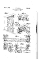
- Figure 1 is a perspective view showing curtains and drapes associated with a window
- Fig. 2 is a horizontal sectional view, partly in plan, showing features of my novel supporting arrangement
- Fig. 3 is a vertical sectional view, partly in elevation and is taken on the line 3-4 of Fig. 2 looking in the direction of the arrows;
- Fig. 4 is a perspective view of a section of mynovel supporting arrangement
- Fig. 5 is a perspective view illustrating a modification of the invention
- Fig. 6 is a horizontal sectional view, partly in plan, illustrating features of the invention as disclosed in Fig. 5;
- Fig. 7 is an elevational view illustrating a detailed feature of the invention.
- C represents a suitable curtain supporting arrangement or cornice which is herein shown as comprising a front section l and side or end sections 2, 2a disposed in substantially parallel relation with respect to each other'and at right angles to said front section I.
- the aforesaid cornice sections are formed from sheet metal and the cornice and sections 2, 2a aresoldered, welded or otherwise suitably secured to the cornice front section I.
- the cornice sections may be of such ornamental configuration as may be suitable or desirable.
- FIG. 2 I have shown spaced members 3, 3a which constitute the vertical side sections of a window or door frame. Disposed at the front of the aforesaid frame are the vertical side members 4, 4a and these are utilized, in a preferred form of the invention, for supporting the aforesaid cornice C.
- pair of spaced members 5 may extend horizontally from the outer, vertical surface I! of each of the members I, 40.
- the members 5 When the members 4, la are formed from wood, the members 5 may be ordinary headed screws which are only partly threaded into said members 4, 4a so that a part of the screw shanks are exposed, Fig. 2. Since the members 5 extend from the respective surfaces lb of the vertical members I, la, it will be obvious that said members 5 are disposed substantially parallel with respect to the front faces 4c of the vertical members 4, la. In other words, the members 5 are disposed substantially parallel with respect to the plane of the window or (1001 frame.
- bracket members 6, fia which are soldered or otherwise suitably secured in vertical relation to the respective As shown, these bracket members are disposed interiorly of the cornice structure and at the extreme ends of the respective cornice end sections 2, 2a.
- bracket members 6, 6a are formed, preferably, from still, non-yielding sheet metal and they are generally square or rectangular when viewed in plan, the arrangement being such that, when the cornice is in position at the top of the window frame, one bracket face 6b takes a position close to and parallel with respect to the adjacent frame or wall surface while another bracket face 6c takes a position close to and parallel with respect to the adjacent vertical member surface lb.
- each bracket is shown as provided with slots 6d of such configuration that the heads of the respective screws 5 pass readily therethrough, these slots being spaced in correspondence with the spacing of the screws 5 as positioned on the aforesaid vertical members 4 and la.
- the face 6c of each bracket is provided with bayonet slots is disposed in aiine'ment with the respective slots 6d and of such dimensionsthat the shanks of the respective screws 5 pass readily therethrough.
- the cornice C may be elevated to substantially its proper position and the bracket slots Gd positioned opposite the heads of the respective'screws 5.
- the length of the cornice is so chosen that the bracket slots 6d may be thus positioned opposite the heads of the respective screws 5 without sepamoved beyond the respective screw heads, the shanks of said screws entering the bayonet slots 6e and seating in the angular sections thereof.
- bracket arrangement of the character described is highly advantageous and practical.
- the brackets when used as described in conjunction with the members 5 support the cornice C in a steady, non-sagging manner even though the weight of the curtains or drapes hanging from said cornice is substantial.
- the cornice may readily and quickly be attached to or detached from the supporting members 5.
- the bracket faces 6b carry sheets or pads I of rubber or other suitable resilient material to thereby prevent marring or scratching of the frame or wall surfaces with which these bracekt faces contact.
- each bar or member 8,811 Disposed interiorly of the cornice C and adjacent the cornice end sections 2, '2a are the respective bars or members 8,811. provided with upwardly facing rack teeth 811. These bars may be supported in horizontal position in any suitable manner.
- metallic brackets 9, 9a may be soldered or welded in each corner of the cornice C, each of these brackets being provided with upwardly extending slots.
- the face 6 of each' of the brackets 6, 6a may be provided with a passage.
- one end of the rack bar 8 may be passed into the passage in the face 6 of the bracket 6 and the other end of said rack bar 8 may be seated in the slot of the bracket 9. In this manner, the rack bar 8 may be firmly seated horizontally at the interior of the cornice end section 2 and, obviously, in a similar manner, the rack bar 8a may be seated adjacent the interior surface of the cornice end section 2a.
- the rack bars 8, 8a are adapted to support, transversely with respect thereto, one or more rods l0 which are horizontally disposed within the cornice C.
- These rods l0 may be of any suitable character although, preferably, they are formed from metallic material such, for example, as sheet metal.
- opposite ends of each bar II] is of inverted U configuration, the U-legs Illa being formed from resilient sheet metal.
- rods l0 may be positioned in such suitable spaced relation on the rack bars 8, 8a as may be desirable.
- These rods carry the various curtains or drapes K, Figs. 1 and 2, which are positioned in front of or at the sides of the window, door or the like.
- an elongated bracket H is soldered or welded to the interior surface of the cornice member I.
- the bracket I l comprises a section which projects laterally from the cornice member I and this lateral section is provided with a plurality of closely spaced holes or perforations Ha.
- a valance V at its upper edge, carries a plurality of spaced hooks I3 and, by proper selection of the holes ll into which the hooks ii are to be inserted, the valance V may be hung in an ornamental manner as well shown in Fig. 1.
- the position taken by the valance may be adjusted within close limits so as to obtain a highly ornamental effect.
- the members 5 for supporting the cornice C are disposed substantially parallel with respect to the plane of the window or door opening. This is a preferred arrangementbut it is to be understood that my invention is not to be limited to this particular arrangement.
- a pair of spaced screws 14 may be disposed at each side of the window or door opening, the screws 14 of each pair being disposed in vertical alinement and all of the screws being disposed substantially at right angles with respect to the plane of the window or door opening.
- the face 60 of the bracket to may be provided with horizontal slots 69 and the faces 6b and 8 of said bracket 6a may be provided with bayonet slots in, Fig. 5.
- the bracket 6, which is to be associated with th pair of screws ll at the left, Fig. 6, has its face 61 provided with horizontal slots 6 these slots corresponding with the above described slots 6g. Further, as indicated, the adjacent surface of the cornice end section 2 is provided with horizontal slots 2b which are alined with the respective slots 61'.
- the faces 6b and 6, of the bracket 6 are provided with bayonet slots 6k, the latter corresponding with the aforesaid bayonet slots 672..
- the cornice In order to associate the bracketed cornice of Fig. 6 with the respective pairs of screws H, the cornice is elevated to approximately its intended position with the horizontal slots Go directly to the right of the respective screws ll of the right hand pair and with the horizontal slots 2b, 67' directly to the right of the respective screws ll of the left hand pair. Thereupon, the cornice assembly is moved to the left, Fig. 6, the screws I passing through the aforesaid horizontal slots and coming to rest, after slight downward movement of the cornice assembly, in the pockets of the respective bayonet slots Sn and 614:. In this manner, said cornice assembly of Fig. 6 is firmly and securely anchored in its intended position.
- pairs of screws 5 need not necessarily be supported by members such as the respective vertical members 4, 4a.
- these screws 5, or equivalent may be supported in any suitable manner so long as they are disposed substantially parallel with respect to the plane of the window or door opening.
- the pairs of screws H, or equivalent may be supported by any suitable members or structure so long as they are disposed substantially perpendicular to the plane of the window or door opening.
- any suitable lamp Ll such, for example, as a neon lamp isisupported by an adjacent wall or frame surface, or in or by the cornice C.
- the lamp Ll may bev scribed is of the indirect lighting type in that the cornice serves as a shield preventing casual observation of the lamp Ll although the rays therefrom pass downwardly to effect illumination of one or more of the curtains K.
- a reflector may be used to direct the rays downwardly in the manner described or upwardly or both downwardly and upwardly at the same time.
- One or more colored glass sections or the like may be interposed in the path of the light beam or beams to obtain such color effects as may be desired.
- a cornice comprising a front section having end sections extending at right angles with respect thereto, of vertically disposed brackets terminally secured to the'respective end sections, each of said brackets having faces meeting to form an angle, said faces being provided, respectively, with slots which merge into each other to form a passage for a shank-like supporting member, the slot in one only of said faces being of bayonet character.
- a cornice comprising a front section having end sections extending at right angles with respect thereto, of a bracket for supporting a valance, means for securing said bracket to the'interior surface of said cornice front section, said bracket being provided with a plurality of closely spaced perforations, said valance being provided with a plurality of hooks spaced substantially further apart than said perforations.
- a cornice comprising a front section having end sections extending at right angles with respect thereto, of vertically disposed brackets terminally secured to the respective'end sections, each of said brackets having faces meeting to form an angle, said faces being provided, respectively, with slots which merge into each other to form a passage for a shank-like supporting member, a bar disposed adjacent each cornice end section, means for securing the bars to said cornice, said bars having closely spaced, upwardly facing rack teeth, and a curtain-supporting rod carried by said bars and being retained in a' selected position by engagement thereof with said rack teeth.
- a cornice comprising a front section having end sections extending at right angles with respect thereto, of vertically disposed brackets terminally secured to the respective end sections, each of said brackets having faces meeting to form an angle, said faces being provided, respectively, with slots which merge into 'each other. to form a passage for a shank-like supporting member, a bar disposed adjacent each cornice end section, means for securing the bars to said cornice, said bars having closely spaced, upwardly'facing rack teeth, a
- each end of said curtain-supporting rod being formed-from spaced members of inverted U configuration, said U members entering between adjacent rack teeth and resiliently engaging surfaces thereof, and a bracket secured'to the interior surface of said cornice front section, said last-mentioned bracket being adapted to support a valance.
Landscapes
- Curtains And Furnishings For Windows Or Doors (AREA)
Description
CURTAIN SUPPORTING ARRANGEMENT Filed Nov. 13, 1953 ATTORN INVENTOR Erwz'nR.Widman ment for curtains,
Patented June 11, 1935 UNITED STATES PATENT OFFICE 10 Claims.
My invention relates to a supporting arrangedrapes or the like.
My invention has particular reference to various novel features and characteristics of a supporting arrangement of the character stated.
Various other objects, advantagesand characteristics of my invention will become apparent from the following detailed description.
My invention resides in the supporting arrangement, features, and details of construction of the character hereinafter described and claimed.
For an understanding of my invention and for an illustration of some of the forms thereof, reference is to be had to the accompanying drawing, in which:
Figure 1 is a perspective view showing curtains and drapes associated with a window;
Fig. 2 is a horizontal sectional view, partly in plan, showing features of my novel supporting arrangement;
Fig. 3 is a vertical sectional view, partly in elevation and is taken on the line 3-4 of Fig. 2 looking in the direction of the arrows;
Fig. 4 is a perspective view of a section of mynovel supporting arrangement;
Fig. 5 is a perspective view illustrating a modification of the invention Fig. 6 is a horizontal sectional view, partly in plan, illustrating features of the invention as disclosed in Fig. 5; and
. Fig. 7 is an elevational view illustrating a detailed feature of the invention.
Referring to the drawing, C represents a suitable curtain supporting arrangement or cornice which is herein shown as comprising a front section l and side or end sections 2, 2a disposed in substantially parallel relation with respect to each other'and at right angles to said front section I. In the form of my invention herein shown, although not necessarily, the aforesaid cornice sections are formed from sheet metal and the cornice and sections 2, 2a aresoldered, welded or otherwise suitably secured to the cornice front section I. Obviously, the cornice sections may be of such ornamental configuration as may be suitable or desirable.
In Fig. 2, I have shown spaced members 3, 3a which constitute the vertical side sections of a window or door frame. Disposed at the front of the aforesaid frame are the vertical side members 4, 4a and these are utilized, in a preferred form of the invention, for supporting the aforesaid cornice C.
To this find, and as shown in Figs. 2 and 3, a
pair of spaced members 5 may extend horizontally from the outer, vertical surface I!) of each of the members I, 40., When the members 4, la are formed from wood, the members 5 may be ordinary headed screws which are only partly threaded into said members 4, 4a so that a part of the screw shanks are exposed, Fig. 2. Since the members 5 extend from the respective surfaces lb of the vertical members I, la, it will be obvious that said members 5 are disposed substantially parallel with respect to the front faces 4c of the vertical members 4, la. In other words, the members 5 are disposed substantially parallel with respect to the plane of the window or (1001 frame.
For securing the cornice C to the members 5, there may be provided a pair of bracket members 6, fia which are soldered or otherwise suitably secured in vertical relation to the respective As shown, these bracket members are disposed interiorly of the cornice structure and at the extreme ends of the respective cornice end sections 2, 2a.
The aforesaid bracket members 6, 6a are formed, preferably, from still, non-yielding sheet metal and they are generally square or rectangular when viewed in plan, the arrangement being such that, when the cornice is in position at the top of the window frame, one bracket face 6b takes a position close to and parallel with respect to the adjacent frame or wall surface while another bracket face 6c takes a position close to and parallel with respect to the adjacent vertical member surface lb.
Referring particularly to Fig. 4, the face 8b of each bracket is shown as provided with slots 6d of such configuration that the heads of the respective screws 5 pass readily therethrough, these slots being spaced in correspondence with the spacing of the screws 5 as positioned on the aforesaid vertical members 4 and la. The face 6c of each bracket is provided with bayonet slots is disposed in aiine'ment with the respective slots 6d and of such dimensionsthat the shanks of the respective screws 5 pass readily therethrough.
with the headed screwsi supported by and projecting in opposite directions from the respective members 4,- la, it will be obvious that the cornice C may be elevated to substantially its proper position and the bracket slots Gd positioned opposite the heads of the respective'screws 5. In this connection, it will be understood that the length of the cornice is so chosen that the bracket slots 6d may be thus positioned opposite the heads of the respective screws 5 without sepamoved beyond the respective screw heads, the shanks of said screws entering the bayonet slots 6e and seating in the angular sections thereof.
when the cornice C is slightly lowered.
It has been demonstrated in practice that a bracket arrangement of the character described is highly advantageous and practical. The brackets when used as described in conjunction with the members 5 support the cornice C in a steady, non-sagging manner even though the weight of the curtains or drapes hanging from said cornice is substantial. Moreover, the cornice may readily and quickly be attached to or detached from the supporting members 5.
Preferably, as shown on the drawing, the bracket faces 6b carry sheets or pads I of rubber or other suitable resilient material to thereby prevent marring or scratching of the frame or wall surfaces with which these bracekt faces contact.
Disposed interiorly of the cornice C and adjacent the cornice end sections 2, '2a are the respective bars or members 8,811. provided with upwardly facing rack teeth 811. These bars may be supported in horizontal position in any suitable manner. For example, metallic brackets 9, 9a may be soldered or welded in each corner of the cornice C, each of these brackets being provided with upwardly extending slots. At the level of these slots, the face 6 of each' of the brackets 6, 6a may be provided with a passage. Accordv ingly, one end of the rack bar 8 may be passed into the passage in the face 6 of the bracket 6 and the other end of said rack bar 8 may be seated in the slot of the bracket 9. In this manner, the rack bar 8 may be firmly seated horizontally at the interior of the cornice end section 2 and, obviously, in a similar manner, the rack bar 8a may be seated adjacent the interior surface of the cornice end section 2a.
The rack bars 8, 8a are adapted to support, transversely with respect thereto, one or more rods l0 which are horizontally disposed within the cornice C. These rods l0 may be of any suitable character although, preferably, they are formed from metallic material such, for example, as sheet metal. In a preferred form of the invention and as shown in Fig. 7, opposite ends of each bar II] is of inverted U configuration, the U-legs Illa being formed from resilient sheet metal. When a rod 10 is to be positioned on the rack bars 8, 8a, these U-legs Illa are moved toward each other and then moved downwardly so as to be positioned, respectively, between adjacent pairs of rack teeth. When thus positioned, the inherent resiliency of said U-legs Illa. causes the rod In to be positively retained in its intended position.
Any desired number of the rods l0 may be positioned in such suitable spaced relation on the rack bars 8, 8a as may be desirable. These rods carry the various curtains or drapes K, Figs. 1 and 2, which are positioned in front of or at the sides of the window, door or the like.
As well shown in Figs. 2, 3 and 4, an elongated bracket H is soldered or welded to the interior surface of the cornice member I. As illustrated, the bracket I l comprises a section which projects laterally from the cornice member I and this lateral section is provided with a plurality of closely spaced holes or perforations Ha. A valance V, at its upper edge, carries a plurality of spaced hooks I3 and, by proper selection of the holes ll into which the hooks ii are to be inserted, the valance V may be hung in an ornamental manner as well shown in Fig. 1. By providing a relatively large number of the perforations Ila compared to the number of the hooks I3, the position taken by the valance may be adjusted within close limits so as to obtain a highly ornamental effect.
In the form of the invention above described, the members 5 for supporting the cornice C are disposed substantially parallel with respect to the plane of the window or door opening. This is a preferred arrangementbut it is to be understood that my invention is not to be limited to this particular arrangement.
Thus as indicated in Figs. 5 and 6, a pair of spaced screws 14 may be disposed at each side of the window or door opening, the screws 14 of each pair being disposed in vertical alinement and all of the screws being disposed substantially at right angles with respect to the plane of the window or door opening.
For association with the pair of screws I4 at the right, Fig. 6, the face 60 of the bracket to may be provided with horizontal slots 69 and the faces 6b and 8 of said bracket 6a may be provided with bayonet slots in, Fig. 5. a
The bracket 6, which is to be associated with th pair of screws ll at the left, Fig. 6, has its face 61 provided with horizontal slots 6 these slots corresponding with the above described slots 6g. Further, as indicated, the adjacent surface of the cornice end section 2 is provided with horizontal slots 2b which are alined with the respective slots 61'. The faces 6b and 6, of the bracket 6 are provided with bayonet slots 6k, the latter corresponding with the aforesaid bayonet slots 672..
In order to associate the bracketed cornice of Fig. 6 with the respective pairs of screws H, the cornice is elevated to approximately its intended position with the horizontal slots Go directly to the right of the respective screws ll of the right hand pair and with the horizontal slots 2b, 67' directly to the right of the respective screws ll of the left hand pair. Thereupon, the cornice assembly is moved to the left, Fig. 6, the screws I passing through the aforesaid horizontal slots and coming to rest, after slight downward movement of the cornice assembly, in the pockets of the respective bayonet slots Sn and 614:. In this manner, said cornice assembly of Fig. 6 is firmly and securely anchored in its intended position.
With the form of my invention illustrated in Figs. 1-4, it shall be understood that the pairs of screws 5 need not necessarily be supported by members such as the respective vertical members 4, 4a. As well, with the form of the invention justnoted, these screws 5, or equivalent, may be supported in any suitable manner so long as they are disposed substantially parallel with respect to the plane of the window or door opening. Similarly, with respect to the form of the invention of Figs. 5 and 6, the pairs of screws H, or equivalent, may be supported by any suitable members or structure so long as they are disposed substantially perpendicular to the plane of the window or door opening.
A further feature of my invention is shown in Fig. 6. As illustrated, any suitable lamp Ll such, for example, as a neon lamp isisupported by an adjacent wall or frame surface, or in or by the cornice C. As indicated, the lamp Ll may bev scribed is of the indirect lighting type in that the cornice serves as a shield preventing casual observation of the lamp Ll although the rays therefrom pass downwardly to effect illumination of one or more of the curtains K. A reflector may be used to direct the rays downwardly in the manner described or upwardly or both downwardly and upwardly at the same time. One or more colored glass sections or the like may be interposed in the path of the light beam or beams to obtain such color effects as may be desired.
While the invention has been described with respect to certain particular preferred examples which give satisfactory results, it will be understood by those skilled in the art after understanding the invention, that various changes and modifications may be made without departing from the spirit and scope of the invention and it is intended therefore in the appended claims to cover all such changes and modifications.
What is claimed as new and desired to be secured by Letters Patent is:
1. The combination with a cornice comprising a front section having end sections extending at right angles with respect thereto, of vertically disposed brackets terminally secured to the respective end sections, each ofsaid brackets having faces meeting to form -an angle, said faces being provided, respectively, with slots which merge into each other to form a passage for a shank-like supporting member.
2. The combination with a cornice comprising a front section having end sections extending at right angles with respect thereto, of vertically disposed brackets terminally secured to the'respective end sections, each of said brackets having faces meeting to form an angle, said faces being provided, respectively, with slots which merge into each other to form a passage for a shank-like supporting member, the slot in one only of said faces being of bayonet character.
3. The combination with a pair of vertically alined, spaced supporting members disposed adjacent each side of a window or door opening and disposed in or parallel with respect to the plane thereof, of a pair of brackets each provided with a pair of slots, each slot being engageable with one of said supporting members, upon movement of said brackets at right angles toward the plane of said window or door opening, and a cornice secured to said brackets.
4. The combination with a cornice having parallel end sections joined by a transverse front section, of a bar disposed adjacent each cornice end 'section, means for securing the bars to said cornice, said bars having closely spaced, upwardly facing rack teeth, and a curtain-supporting rod carried by said bars and being retained in a selected position by engagement thereof with said rack teeth.
5. The combination with a cornice having parallel end sections joined by, a transverse front section, of a bar disposed adjacent each cornice end section, means for securing the bars to said cornice, said bars having closely spaced, upwardly facing rack teeth, and a' curtain-supporting rod carried by said bars and being retained in a selected position by engagement thereof with said rack teeth, each end of said curtain-supporting rod being formed from spaced members of inverted U configuration, said U members en ing between adjacent rack teeth and resiliently engaging surfaces thereof.
6. The combination with a cornice having parallel end sections joined by a transverse front section, of a bracket terminally secured to one of said end sections, the juncture of said last named end section with said front section, and a bar carried by said brackets, said bar being adapted to support one end of a curtain-supporting rod.
7. The combination with a cornice comprising a front section having end sections extending at right angles with respect thereto, of a bracket for supporting a valance, means for securing said bracket to the'interior surface of said cornice front section, said bracket being provided with a plurality of closely spaced perforations, said valance being provided with a plurality of hooks spaced substantially further apart than said perforations.
8. The combination with a cornice comprising a front section having end sections extending at right angles with respect thereto, of vertically disposed brackets terminally secured to the respective'end sections, each of said brackets having faces meeting to form an angle, said faces being provided, respectively, with slots which merge into each other to form a passage for a shank-like supporting member, a bar disposed adjacent each cornice end section, means for securing the bars to said cornice, said bars having closely spaced, upwardly facing rack teeth, and a curtain-supporting rod carried by said bars and being retained in a' selected position by engagement thereof with said rack teeth.
9. The combination with a cornice comprising a front section having end sections extending at right angles with respect thereto, of vertically disposed brackets terminally secured to the respective end sections, each of said brackets having faces meeting to form an angle, said faces being provided, respectively, with slots which merge into 'each other. to form a passage for a shank-like supporting member, a bar disposed adjacent each cornice end section, means for securing the bars to said cornice, said bars having closely spaced, upwardly'facing rack teeth, a
curtain-supporting rod carried by said bars and being retained in a selected position by engagement thereof with said rack teeth, each end of said curtain-supporting rod being formed-from spaced members of inverted U configuration, said U members entering between adjacent rack teeth and resiliently engaging surfaces thereof, and a bracket secured'to the interior surface of said cornice front section, said last-mentioned bracket being adapted to support a valance.
10. The combination with a cornice having parallel end sections joined by a transverse front section, of a bar disposed adjacent each cornice end section, means for securing the bars to said cornice in horizontal position, said bars having spaced, upwardly projecting teeth, and a curtain-supporting rod carried by said bars, the ends of said rod engaging and coacting with said a bracket secured adjacent teeth to thereby prevent casual movement of said
Priority Applications (1)
| Application Number | Priority Date | Filing Date | Title |
|---|---|---|---|
| US697748A US2004262A (en) | 1933-11-13 | 1933-11-13 | Curtain supporting arrangement |
Applications Claiming Priority (1)
| Application Number | Priority Date | Filing Date | Title |
|---|---|---|---|
| US697748A US2004262A (en) | 1933-11-13 | 1933-11-13 | Curtain supporting arrangement |
Publications (1)
| Publication Number | Publication Date |
|---|---|
| US2004262A true US2004262A (en) | 1935-06-11 |
Family
ID=24802369
Family Applications (1)
| Application Number | Title | Priority Date | Filing Date |
|---|---|---|---|
| US697748A Expired - Lifetime US2004262A (en) | 1933-11-13 | 1933-11-13 | Curtain supporting arrangement |
Country Status (1)
| Country | Link |
|---|---|
| US (1) | US2004262A (en) |
Cited By (8)
| Publication number | Priority date | Publication date | Assignee | Title |
|---|---|---|---|---|
| US2478699A (en) * | 1944-12-30 | 1949-08-09 | Lange Morris | Illuminated background |
| US2526806A (en) * | 1949-02-09 | 1950-10-24 | Charbonneau Robert Jean | Window cornice board assembly |
| US2528132A (en) * | 1947-10-03 | 1950-10-31 | Ronald L Gibson | Combined reflector and venetian blind housing |
| US2536947A (en) * | 1949-03-23 | 1951-01-02 | Henry F Lavorgna | Adjustable window valance |
| US2662163A (en) * | 1950-08-10 | 1953-12-08 | William J Mollner | Combination lighting fixture and curtain holder |
| US3007036A (en) * | 1957-08-28 | 1961-10-31 | Gen Electric | Wall lighting unit |
| US6094796A (en) * | 1997-11-06 | 2000-08-01 | Biro; Michael Julius | Manufacturing method for a valance |
| US6659154B2 (en) | 2002-04-26 | 2003-12-09 | Isoteck Corporation | Valance with adjustable mounting features |
-
1933
- 1933-11-13 US US697748A patent/US2004262A/en not_active Expired - Lifetime
Cited By (8)
| Publication number | Priority date | Publication date | Assignee | Title |
|---|---|---|---|---|
| US2478699A (en) * | 1944-12-30 | 1949-08-09 | Lange Morris | Illuminated background |
| US2528132A (en) * | 1947-10-03 | 1950-10-31 | Ronald L Gibson | Combined reflector and venetian blind housing |
| US2526806A (en) * | 1949-02-09 | 1950-10-24 | Charbonneau Robert Jean | Window cornice board assembly |
| US2536947A (en) * | 1949-03-23 | 1951-01-02 | Henry F Lavorgna | Adjustable window valance |
| US2662163A (en) * | 1950-08-10 | 1953-12-08 | William J Mollner | Combination lighting fixture and curtain holder |
| US3007036A (en) * | 1957-08-28 | 1961-10-31 | Gen Electric | Wall lighting unit |
| US6094796A (en) * | 1997-11-06 | 2000-08-01 | Biro; Michael Julius | Manufacturing method for a valance |
| US6659154B2 (en) | 2002-04-26 | 2003-12-09 | Isoteck Corporation | Valance with adjustable mounting features |
Similar Documents
| Publication | Publication Date | Title |
|---|---|---|
| US2974918A (en) | Universal bracket support | |
| US2031718A (en) | Display device for merchandise | |
| US2004262A (en) | Curtain supporting arrangement | |
| US2289451A (en) | Corner shelf | |
| US2848184A (en) | Curtain fixture | |
| US2223674A (en) | Picture frame | |
| US4653712A (en) | Window shelf brackets | |
| US2056874A (en) | Curtain fixture | |
| US1593114A (en) | Curtain-rod bracket | |
| US2171221A (en) | Supporting structure for porcelain enameled pans | |
| US2233430A (en) | Curtain and shade support | |
| US3345678A (en) | Support for draperies and the like | |
| US993753A (en) | Shelf-support. | |
| US2247954A (en) | Adjustable window valance | |
| US2234594A (en) | Drapery support | |
| US2589744A (en) | Simulated window | |
| US1454557A (en) | Combination curtain and shade holder | |
| US1751062A (en) | Combined valance-board support and curtain-rod bracket | |
| US1956501A (en) | Curtain rod holder | |
| US1017765A (en) | Curtain-fixture. | |
| US1344298A (en) | Combined curtain and shade support | |
| US1559081A (en) | Adjustable combination window-shade and curtain-pole holder | |
| US1713299A (en) | Multiple-rod bracket | |
| US1507997A (en) | Curtain-pole and shade bracket | |
| US1609837A (en) | Picture hanger |