US6094796A - Manufacturing method for a valance - Google Patents
Manufacturing method for a valance Download PDFInfo
- Publication number
- US6094796A US6094796A US08/965,679 US96567997A US6094796A US 6094796 A US6094796 A US 6094796A US 96567997 A US96567997 A US 96567997A US 6094796 A US6094796 A US 6094796A
- Authority
- US
- United States
- Prior art keywords
- trim strip
- extending
- central
- remaining portion
- strip
- Prior art date
- Legal status (The legal status is an assumption and is not a legal conclusion. Google has not performed a legal analysis and makes no representation as to the accuracy of the status listed.)
- Expired - Lifetime
Links
Images


Classifications
-
- A—HUMAN NECESSITIES
- A47—FURNITURE; DOMESTIC ARTICLES OR APPLIANCES; COFFEE MILLS; SPICE MILLS; SUCTION CLEANERS IN GENERAL
- A47H—FURNISHINGS FOR WINDOWS OR DOORS
- A47H2/00—Pelmets or the like
-
- A—HUMAN NECESSITIES
- A47—FURNITURE; DOMESTIC ARTICLES OR APPLIANCES; COFFEE MILLS; SPICE MILLS; SUCTION CLEANERS IN GENERAL
- A47H—FURNISHINGS FOR WINDOWS OR DOORS
- A47H2201/00—Means for connecting curtains
- A47H2201/02—Hook-and-loop fasteners
-
- Y—GENERAL TAGGING OF NEW TECHNOLOGICAL DEVELOPMENTS; GENERAL TAGGING OF CROSS-SECTIONAL TECHNOLOGIES SPANNING OVER SEVERAL SECTIONS OF THE IPC; TECHNICAL SUBJECTS COVERED BY FORMER USPC CROSS-REFERENCE ART COLLECTIONS [XRACs] AND DIGESTS
- Y10—TECHNICAL SUBJECTS COVERED BY FORMER USPC
- Y10T—TECHNICAL SUBJECTS COVERED BY FORMER US CLASSIFICATION
- Y10T29/00—Metal working
- Y10T29/49—Method of mechanical manufacture
- Y10T29/49789—Obtaining plural product pieces from unitary workpiece
-
- Y—GENERAL TAGGING OF NEW TECHNOLOGICAL DEVELOPMENTS; GENERAL TAGGING OF CROSS-SECTIONAL TECHNOLOGIES SPANNING OVER SEVERAL SECTIONS OF THE IPC; TECHNICAL SUBJECTS COVERED BY FORMER USPC CROSS-REFERENCE ART COLLECTIONS [XRACs] AND DIGESTS
- Y10—TECHNICAL SUBJECTS COVERED BY FORMER USPC
- Y10T—TECHNICAL SUBJECTS COVERED BY FORMER US CLASSIFICATION
- Y10T29/00—Metal working
- Y10T29/49—Method of mechanical manufacture
- Y10T29/49826—Assembling or joining
- Y10T29/49893—Peripheral joining of opposed mirror image parts to form a hollow body
-
- Y—GENERAL TAGGING OF NEW TECHNOLOGICAL DEVELOPMENTS; GENERAL TAGGING OF CROSS-SECTIONAL TECHNOLOGIES SPANNING OVER SEVERAL SECTIONS OF THE IPC; TECHNICAL SUBJECTS COVERED BY FORMER USPC CROSS-REFERENCE ART COLLECTIONS [XRACs] AND DIGESTS
- Y10—TECHNICAL SUBJECTS COVERED BY FORMER USPC
- Y10T—TECHNICAL SUBJECTS COVERED BY FORMER US CLASSIFICATION
- Y10T83/00—Cutting
- Y10T83/768—Rotatable disc tool pair or tool and carrier
- Y10T83/7684—With means to support work relative to tool[s]
- Y10T83/773—Work-support includes passageway for tool [e.g., slotted table]
-
- Y—GENERAL TAGGING OF NEW TECHNOLOGICAL DEVELOPMENTS; GENERAL TAGGING OF CROSS-SECTIONAL TECHNOLOGIES SPANNING OVER SEVERAL SECTIONS OF THE IPC; TECHNICAL SUBJECTS COVERED BY FORMER USPC CROSS-REFERENCE ART COLLECTIONS [XRACs] AND DIGESTS
- Y10—TECHNICAL SUBJECTS COVERED BY FORMER USPC
- Y10T—TECHNICAL SUBJECTS COVERED BY FORMER US CLASSIFICATION
- Y10T83/00—Cutting
- Y10T83/869—Means to drive or to guide tool
- Y10T83/8773—Bevel or miter cut
Definitions
- This invention relates to a decorative valance for attachment at the top of a window around a mechanism for the attachment and movement of a window covering, and, more particularly, to a manufacturing method combining mitered sections of extruded stock with a heat-formed decorative trim strip to form such a valance.
- Valances, or cornices have been used for many years as interior decorations covering the mechanisms for attachment and movement of window coverings, such as curtains, drapes, shades, and blinds. Such mechanisms are typically adjacent the top of windows, with the window coverings hanging downward therefrom.
- window coverings such as curtains, drapes, shades, and blinds.
- valances where used to cover the cord and pulley arrangements used to operate pull-up curtains developed in Europe in the latter part of the seventeenth century.
- valences Due to the large number of widths and types of windows, and due to the variety of window coverings which must be accommodated, conventional methods for making valences have relied on materials cut to size and assembled for individual windows. For example, early valances were wooden box structures covered with fabric. More recently, buckram has been used, being fastened along the front face and ends of a board mounted to the wall above a window by means of brackets.
- the buckram covering which is composed of a coarse linen or hemp cloth stiffened by sizing, is cut to shape, extending downward from the board to a decorative edge having, for example, a scalloped pattern, and folded at the corners to form return sections extending along the ends of the board to the wall.
- a valance of this type conventionally consists of a front member extending above the window and of a end member extending toward the wall at each end of the front member.
- a particular problem with this type of valance concerns the treatment of the decorative strip at the corners where the front member and the end members are joined.
- One conventional method of dealing with this problem has been to terminate the decorative strip at the corner, so that the portions of the decorative strip extending along the end members of the valance are separate from the portion extending along the front member thereof.
- a problem with this method arises from the fact that the decorative strips do not lie flat; they are bowed so that an aesthetically undesirable large gap is seen between the strip members extending in mutually perpendicular directions away from the corner.
- Another conventional method for dealing with the decorative strip at the valance corners is to provide an underlying corner member providing a gentle curve between the flat surfaces on which the strip is held in the strip is held in the end and front members.
- the strip is curved around each corner member at a generous radius established by the corner member. This generous radius is needed to allow the curvature of the strip.
- One disadvantage of this method is overall appearance of the finished valance is established and therefore limited by the method chosen for handling the corners. The overall appearance is one of straight lines and flat surfaces being joined by curved surfaces having generous radii. This type of appearance was popularized in the mid- to late-1930's, being incorporated into the cover designs of clocks, radios, thermostats, etc.
- valances made with joined extrusions tend to have central members extending rearward toward the wall for attachment to the end members, which are made from stock of differing cross members. What is needed is a method allowing relatively thin extrusions, common with one another, to be joined at mitered edges.
- a first objective of the present invention is to provide a method for manufacturing a valance having a central member, two end members, and a decorative strip formed at square corners to extend along the central member and end members.
- Another objective of the present invention is to provide a method for manufacturing a valance having minimum complexity where the central and end members are joined at corners.
- Another objective of the present invention is to provide a method for manufacturing a valance having a central member and end members formed from common extruded stock.
- Another objective of the present invention is to provide a method for manufacturing a valance suitable to extend within a bay window.
- Another objective of the present invention is to provide a method for manufacturing a valance including downward hanging fabric materials which can be easily removed for cleaning and replaced.
- a method for constructing a valance from materials comprising an elongated structural member having a uniform transverse sectional shape, including an inner surface with a downwardly disposed upper attachment slot and an upwardly disposed lower attachment slot, and an outer surface with a downwardly directed upper trim strip receiving slot and an upwardly directed lower trim strip receiving slot, a trim strip, and first and second "L"-shaped brackets, wherein the method includes steps of:
- trim strip into a central portion essentially equal in length to the central member and first and second end portions extending in an inward direction essentially perpendicular to the central porion;
- a bracket including upper and lower sections, for connecting upper and lower valance frames.
- the upper section has upper and lower tabs for removably engaging features of the upper valance frame.
- the lower section which is pivotally mounted on the upper section, has first and second tabs for removably engaging features of the lower valance frame.
- FIG. 1 is an exploded isometric view of a valance built in accordance with conventional methods
- FIG. 2 is a fragmentary exploded isometric view of a valance built in accordance with the present invention
- FIG. 3 is a transverse cross-sectional view of a frame member within the valance of FIG. 2, together with a trim strip fastened thereto;
- FIG. 4 is a longitudinal cross-sectional view of a die set used to produce an extrusion forming the frame member of FIG. 3;
- FIG. 5 is an end elevational view of a first die within the die set of FIG. 4;
- FIG. 6 is an end elevational view of a second die within the die set of FIG. 4;
- FIG. 7 is an end elevational view of a third die within the die set of FIG. 5;
- FIG. 8 is a perspective view of a sawing station used to mitered edges of members within the valance of FIG. 2;
- FIG. 9 is an isometric view schematically showing a first end member of the valance of FIG. 2 being cut within the sawing station of FIG. 8;
- FIG. 10 is an isometric view schematically showing a second end member of the valance of FIG. 2 being cut within the sawing station of FIG. 8;
- FIG. 11 is an isometric view schematically showing a first end of a central member within the valance of FIG. 2 being cut within the sawing station of FIG. 8;
- FIG. 12 is an isometric view schematically shown a second end of a central member within the valance of FIG. 2 being cut within the sawing station of FIG. 8;
- FIG. 13 is an isometric view of a heating station used in heat forming a trim strip of the valance of FIG. 2;
- FIG. 14 is a fragmentary isometric view of an interconnected pair of the valances of FIG. 2;
- FIG. 15 is a plan view of a valance made according to the present invention to fit within a bay window.
- FIG. 16 is a transverse sectional view of an elongated member which is tormed as part of a frame of a valance.
- FIG. 1 is an exploded isometric view of a valance 10 built in accordance with conventional methods.
- This valance 10 includes a central member 12, a pair of end members 14, a pair of rounded corner members 16, four rounded flange members 18, and a decorative strip 20.
- tabs 22 of rounded corner members 16 are pressed into slots 24 extending along a rear surface of the central member 12, and the decorative strip 20 is slid into slots 26 extending along a central surface 28 of the central member 12.
- the decorative strip 20 is formed around curved surfaces 30 of rounded corner members 16 to extend within slots 32 or each end member 14 as these members are pressed in place, with a tab 34 of a rounded corner member 16 extending into the slots 36 of an adjacent end member 14.
- a pair of rounded flange members 18 are pressed into place from above and below each rounded corner member 16, with a pin 38 from each flange member 18 extending into a slotted hole 40 within the corner m ember 16.
- FIG. 2 is an exploded isometric view of a valance 44 built in accordance with the present invention.
- This valance 44 includes a central member 46, a pair of end members 48, 49, a pair of corner brackets 50, and a decorative strip 52.
- the central member 46 is depicted with a central section removed to show a mounting bracket 53 used to attach the valance 44 to surfaces of the building structure (not shown).
- the central member 46 and the end members 48, 49 are members of a frame generally built to extend adjacent a window.
- the decorative strip 52 is heat-formed at corners 54, which define end strip portions 56 and a central strip portion 58.
- the end members 48, 49 and the central member 46 are similar in transverse crosssection, and may therefore be cut from the same extruded plastic stock, which includes an inner surface 60 and an outer surface 62.
- the inner surface 60 has an upper attachment slot 63, extending within an inward-extending "L"-shaped section 64, and a lower attachment slot 66, extending within an inward-extending "L"-shaped section 68.
- the outer surface 62 includes an outward-extending upper decorative curved portion 70, which returns inward to form an upper trim strip receiving slot 72.
- the outer surface 62 further includes an outward-extending lower decorative curved portion 74, which returns inward to form a lower trim strip receiving slot 76.
- These trim strip receiving slots 72, 76 extend along opposite sides of a planar trim strip receiving surface 77, along which the trim strip 52 extends. To achieve a desired aesthetic effect, upper curved portion 70 extends farther outward than lower curved portion 74.
- the mating edges 78 of central member 46 and of end members 48, 49 are mitered, being individually cut along a plane extending at a 45-degree angle to the planar trim strip receiving surface 77. Cutting these members 46, 48, 49 in this way ensures that a trim strip formed along a line extending perpendicularly between its longitudinal edges will extend within the planar trim strip receiving surfaces of each member.
- the two sides of 50 each corner bracket 51 extend into attachment slots 63, 66 of the central member 46 and of the adjoining end members 48, 49.
- the upper edge of decorative strip 52 extends within upper trim strip receiving slots 72 of the central member 46 and of end members 48, 49.
- the lower edge of decorative strip 52 extends within lower trim strip receiving slots 76 of the central member 46 and of end members 48, 49.
- Mounting bracket 53 incudes an upper tab 79 and a lower tab 80, which are formed in alignment with one another to engage the surfaces of upper attachment slot 63 and lower attachment slot 66, respectively.
- the bracket 53 is brought into engagement with the central member 46, being rotated through an angle in the direction of arrow 81 which is sufficient to allow the movement of tabs 79, 80 past the "L"-shaped structures 64, 68, and being subsequently rotated opposite the direction of arrow 81 so that the tabs 79, 80 are rotated into engagement within the slots 63, 66.
- the bracket 53 also includes a rearward-extending attachment tab 82 having a hole 83 and a slot 83a, which may be used, for example, to attach the bracket 53 to the ceiling of a structure in which the valance 44 is to be placed.
- the bracket 53 also includes additional holes 83b, which may be used to mount the bracket 53 to a vertical surface of another bracket.
- FIG. 3 is a transverse cross sectional view of an elongated member 84 from which the central member 46 and both of the end members 48, 49 (shown in FIG. 2) are made, along with the trim strip 52. These three members 46, 48, and 49 are thus identical in transverse sectional shape.
- the trim strip 52 is naturally bowed outward, as it is shown with solid lines in FIG. 3. However, each heat-formed corner 54 (shown in FIG. 2) forces the trim strip 52 into a flat condition, as indicated by dashed lines 85 in FIG. 3.
- the tolerance for variation in width of the trim strip 52 allows this strip 52 to be brought into engagement within the slots 72, 76 by movement generally in the normal direction of arrow 88, with the flattened end portions being snapped into place. This capability is particularly important, since the central strip portion 58 of preformed trim strip 52 must be brought into place within the trim strip receiving slots 72, 76 of central member 46 in a normal direction while end strip portions 56 are slid within the trim strip receiving slots 72, 76 of end members 48, 49.
- the tolerance thus provided for the engagement of the trim strip 52 within the slots 72, 76 also provides a tolerance for variations in the difference between the length of central strip portion 58 and the length of central member 46.
- the elongated member 84 includes decorative coatings 89 extending along its visible surfaces, which exclude the surface hidden by trim strip 52 and inner surface 60.
- the decorative coating 89 being a thin layer covering the readily visible surfaces of the elongated member 84, may include coloring and texturing agents raising the cost of the material, of which this coating 89 is composed, to a level several times as high as that of the material composing the remaining portion of the elongated member 84 without substantially increasing the cost of the finished product.
- the elongated member 84 may also include one or more decorative adhesive strips 89a, providing, for example, a bright gold or silver finished appearance.
- the decorative adhesive strips 89a may be used in addition to, or in place of, decorative coatings 89. Both the decorative coating 89 and the adhesive strips 89a are applied to the elongated member 84 before it is cut up to form central member 46 and end members 48, 49, with these decorative features 89, 89a being brought into alignment as the members 46, 48, and 49 are subsequently assembled together.
- the valance 44 having been built according to the present invention has a number of advantages over the conventional valance 10, shown in FIG. 1.
- the valance 44 is formed to show the desired appearance of squared corners on the trim strip.
- a single type of extruded stock is used both for the central member 46 and for the end members 48, 49.
- Attachment slots 63, 66 are used both for corner attachment with brackets 51 and for the attachment of the valance to the structure (not shown) in which it is placed, through one or more attachment brackets 53.
- the use of decorative coatings 89 allows wide variations in the appearance of the product without substantially increasing its manufacturing cost.
- FIGS. 4-14 A preferred process for manufacturing the valance shown in FIGS. 2 and 3 will now be discussed, with particular reference being made to FIGS. 4-14.
- This discussion begins with manufacturing the elongated section 84 (shown in FIG. 3) by means of an extrusion process using a die set shown in FIGS. 4-7.
- the elongated section 84 is composed of a thermoplastic material which may be formed by means of the extrusion process, such as polyvinyl chloride (PVC).
- PVC polyvinyl chloride
- FIGS. 4-7 are views of an extrusion die set 90 used to form the elongated section 84 (shown in FIG. 3), with FIG. 4 being a longitudinal cross sectional view of the die set 90, while FIG. 5 is an end elevation of first die 91 therein, FIG. 6 is an end elevation of a second die 92 therein, and FIG. 7 is an end elevation of a third die 93 therein.
- FIGS. 5, 6, 7, are taken in the direction of arrow 94.
- a first softened thermoplastic material is driven into a slot 95 of first die 91, by means of a first extruding machine (not shown), which may be of a type well known to those of skilled in the art of making plastic extrusions. Movement through this first slot 95 forms the thermoplastic material to have an essentially rectangular transverse cross-sectional shape with rounded ends.
- second die 92 includes an aperture 96 having a shape which is approximately the transverse sectional shape desired for the elongated section 84.
- a second softened thermoplastic material is driven into a slot 97 within the second die 92, by means of a second extruding machine (also not shown), which may also be of a type well known to those skilled in the art of making plastic extrusions.
- This second thermoplastic material which is also of a type, such as PVC, capable of being formed into specific shapes through the extrusion process, includes coloring agents determined to produce an aesthetically attractive appearance in the visible portions of the valance made using the elongated section 84.
- the second thermoplastic material flows under pressure from the slot 97 through channels 97a into troughs 97b extending adjacent the portions of the aperture 96 corresponding to surfaces of the elongated extrusion 84 to be covered with decorative coatings 89.
- the first and second thermoplastic materials flow through aperture 96 in the direction of arrow 94, with the second thermoplastic material flowing in a layer extending along the adjacent surfaces of the first material to form the decorative coatings 89, into a chamber 98 within the second die 92. Within this chamber 98, compressive stresses within the extruded material are reduced.
- the extruded material leaving die 92 in the direction of arrow 94 is driven through an aperture 99 in the third die 93.
- This aperture 99 also has a shape which is approximately the transverse sectional shape desired for the elongated section 84.
- the extruded material then flows through aperture 99 in the direction of arrow 94 onto a conveyor system (not shown) on which it is cooled and cut into desired lengths.
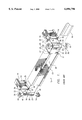
- FIG. 8 is a perspective view of a sawing station 100 used to form the mitered edges 78 of central member 46 and end members 48, 49 of the valance shown in FIG. 2.
- the sawing station 100 includes a rotary saw blade 102 driven in rotation by a motor 104 and movable in the direction of arrow 106 by depressing a handle 108. While a safety guard 110 extends around most of the periphery of saw blade 102, the exposed portion 112 of the saw blade 102 can be moved downward, in the direction of arrow 106, into a slot 114 within a guiding fixture 116.
- the guiding fixture 116 includes a number of longitudinally extending surfaces 118, which are configured for engaging longitudinally extending features of an extruded member (not shown) used to form the central member 46 and the end members 48, 49.
- the extruded member is an elongated member having the transverse sectional shape of central member 46 and end members 48, 49, the reference numerals identifying portions of these members 46, 48, and 49 are used herein to describe features of the extruded member.
- the extruded member, or a portion thereof is placed on the guiding fixture with outer surface 62 facing upward, and with a flat portion 120 of the inner surface 60 planar trim strip receiving surface 77 facing downward and extending along the surface 122 of the fixture 116.
- This inner surface portion 120 is parallel to the trim strip receiving surface 77.
- the "L"-shaped structures 64, 68 extend outside the edges of this surface portion 120.
- the inward-extending edges of curved portions 70, 74 fit, together with "L"-shaped structures 64, 66 extend downward within slots 124, which extend downward from surface 122 of the fixture 116.
- fixture 116 allows the extruded member, or a portion thereof, to be placed on the fixture 116 and moved in the longitudinal direction of arrow 126 and opposite thereto.
- Saw blade 102 forms a cutting plane having an angle 127 of 45 degrees with the guiding surface 122.
- guiding tabs 128 are engaged within the attachment slots 63, 66 of the member being cut. These tabs 128 require that the member being cut must be brought toward the cutting plane in or opposite the direction of arrow 126.
- the fixture 116 also includes a stopping pin 130, which may be placed in any of three holes 132, 134,136 controlling the length of an end member 48, 49 being cut or into a hole 138 controlling length of the central member 46 as it is cut.
- FIGS. 9-12 are isometric views of the sequential cutting operations occurring within the cutting apparatus 100 to form the mitered edges 78 of valance members 46, 48, 49.
- the extruded member is cut into a predetermined-length portion 140.
- the length of this portion 140 is determined according to the type of valance to be constructed and the track length of the window covering with which the valance is to be used. For example, if the valance is being made for a 9 -cm (3.5-inch) IB valance system, which extends, along with the window covering, within a slot in a structure wall, the predetermined length is equal to the track length plus 21.6 cm (8.5 inches).
- the predetermined length is equal to the track length plus 39.4 cm (15.5 inches). If the valance is being made for a 5-cm (2-inch) OB valance system, the predetermined length is equal to the track length plus 26.7 cm (10.5 inches). Since, following the miter cutting process, the ends 142, 144 of the predetermined-length portion 140 become the square ends of the end members 48, 49, these cuts are made precisely, using apparatus of a well-known type, such as a table saw.
- the position chosen for stopping pin 130 is also dependent on the type of valance structure being built, but not on the track length of the window covering. For example, if the valance is being made for a 9-cm (3.5-inch) IB valance system, the stopping pin 130 is placed in the leftmost hole 132. If the valance is being made for a 5-cm (2-inch) OB valance system, the stopping pin 130 is placed in the central hole 134. If the valance is being made for a 9-cm (3.5-inch) OB valance system, the stopping pin 130 is placed in the rightmost hole 136. In any case, the first mitering cut is made, in the configuration of FIG.
- the rotating saw blade 102 is brought downward, in the direction of arrow 106 along the cutting plane 146.
- the end member 48 is removed from the mitering process.
- the first remaining portion 148 from predetermined-length member 144 is rotated, so that the remaining square end 144 is brought into contact with the stopping pin 130, with the remaining portion 148 extending opposite the direction of arrow 126.
- This configuration is shown in FIG. 10.
- the rotating saw blade 102 is lowered, the remaining end member 49 is cut away from the first remaining portion 148.
- the first two mitering cuts separate the end members 48, 49 from opposite ends of the original predetermined-length member 140. So long as these sections are formed from opposite, square-cut ends in this way, it is immaterial which of the end members 48, 49 is cut away first.
- the stopping pin 130 is next placed in the hole 138 controlling the length of central member 46 (shown in FIG. 2) as it is formed in the mitering process.
- the second remaining portion 150 from the operation of FIG. 10, has a surface 152 inclined at a 45-degree angle at each end, but these surfaces 152 are inclined in the wrong direction, decreasing the length of outer surface 62 below that of inner surface 60. Therefore, this second remaining portion 150 is next placed in the apparatus as indicated in FIG. 11, to extend from the stopping pin 130 in the direction of arrow 126.
- a first small scrap portion 154 is removed from a third remaining portion 156.
- the third remaining portion 156 has an end 158 cut to be parallel to its remaining end 152. Therefore this third remaining portion is next placed in the apparatus as indicated in FIG. 7, to extend from the stopping pin in the direction of arrow 126, with the most recently cut end 158 facing away from cutting plane 146.
- a second small scrap portion 160 is removed from the remaining portion, which is at this point formed as the central member 46.
- the process of cutting scrap portions 158,160 may be begun at either end of the second remaining portion 150, so long as a scrap portion 158, 160 is cut from each end of this portion 150.
- FIG. 13 is an isometric view of a heating station 174 used in the forming of trim strip material 176 into the shape of decorative strip 52 (shown in FIG. 2), with heat-formed corners 54 defining end strip portions 56 and a central strip portion 58.
- the trim strip material 176 is composed of a thermoplastic material, such as polyvinyl chloride.
- the heating station 174 includes a heating unit 178 extending centrally from front to rear, having a resistive heater extending to provide a narrow band of heat along an upper surface 180, and a pressure pad 182, which is pivoted downward by means of a handle 184 rotating about a pivot shaft 186.
- the heating station 174 also includes a pair of support tables 187, along which the trim strip material 176 is placed.
- the trim strip material is marked to determine the places at which the corners 54 will be formed.
- a successful method for placing these markings has been determined to be the placement of a flat portion 178 of the front surface 62 of central member 46 above the trim strip material 176, with pencil markings 188 then being made on the trim strip material 176 along each edge 78 of the flat portion 178.
- These pencil markings 188 must also be made with sufficient material remaining at each end of the trim strip material 176 to form an end strip portion 56.
- the trim strip material 176 is placed on the upper surfaces 190 of tables 187, in alignment with a line 192, which in turn extends along these surfaces 190 in a direction perpendicular to the upper heating surface 180. This placement assures that a bend made along the heated portion of the trim strip material 176 is perpendicular to the edges of the trim strip material. Local heating occurs as the trim strip material is held against the upper heating surface 180 by means of the pressure pad 182. Then, before substantial cooling occurs, the trim strip material 176 is removed from the heating station 174 and bent downward at the heated area, placing the heated area in compression to a substantially perpendicular angle, which may, for example, include a ten-degree overbend compensating for the angle through which the material is expected to spring back as it cools.
- This process is next repeated at the other end of the trim strip material 176, with a second end portion 56 to be formed.
- the associated pencil marking 188 is placed about 3 mm (0.125 inch) past the center of heating surface 180, in a direction elongating central portion 58 extending between the corners 54.
- This process begins with inserting a side 50 of a corner bracket 51 into the attachment slots 63, 66, at each end of central member 46.
- the central portion 58 of formed decorative strip 52 is brought into place within the trim strip receiving slots 72, 76 of central member 46.
- this assembly step is facilitated by the fact that the decorative strip is easily bowed; at the ends it is snapped, where stiffness has resulted from the forming operation, the central portion 58 is snapped into place by squeezing it against the central member 46.
- end members 48, 49 are slipped into place with the second legs 50 of corner brackets 51 extending within the attachment slots 63 and 66 of these end members.
- the desired lengths of the end portions 56 of the decorative strip 52 are indicated with pencil markings at the square ends of these end members 48, 49, which are then slipped off the legs 50 of corner brackets 51.
- the end portions 56 of the decorative strip 52 are cut at these pencil markings.
- end members 48, 49 are reassembled onto the legs 50 of corner brackets 51, and with edges of the end portions 56 of the decorative strip 52 extending within trim strip receiving slots 72, 76 of each end member 48, 49.
- attachment brackets 53 may be assembled to the central member 46, being rotated into place in or opposite the direction of arrow 81 so that tabs 80, 82 are brought into attachment slots 63, 66.
- end members 48, 49 and central member 46 While adhesives may be used to secure the attachment of end members 48, 49 and central member 46 to end members 51, they are generally not required because the frictional forces between both the brackets 51 and the end members 48, 49, and between the end portions 56 of decorative trim strip 52 and the end members 48, 49 are sufficient to hold these end members 48, and 49 in place. Furthermore, the shape of decorative trim strip 52 prevents outward movement of corner brackets 51, holding their legs 50 inserted fully within the associated slots 63, 66 of central member 62.
- Each connecting bracket 210 includes an upper segment 212 and a lower segment 214, which is rotatably mounted on the upper segment 212 at a pivot 216.
- the upper segment 212 includes an inward-extending section 217 providing for the inward displacement of the lower frame 204 relative to the upper frame 202.
- the upper segment 212 is brought into engagement with the central member 218 of upper frame 202 by pivoting this segment 212 in or opposite the direction of arrow 220, so that an upper tab 222 is brought into an upper attachment slot 224 of the central member 218, while a lower tab 226 is brought into a lower attachment slot 228 of this member 218.
- the lower segment 214 is brought into engagement with the central member 208 of lower frame 204 by rotation about pivot 216, so that the opposing tabs 230 are individually brought into engagement with an upper attachment slot 232 and a lower attachment slot 234.
- the number of attachment brackets 53 used to hold upper frame 202 in place within the building structure is typically two or more, with the actual number being determined by the length of central member 218.
- the number of connecting brackets 210 is typically two or more, with the actual number being determined by the length of central member 218. Additional connecting brackets 218 may be used to connect the lower frame 204 to a third frame (not shown) extending therebelow.
- FIG. 15 is a partially-exploded plan view of an alternative valance 240 built in accordance with a version of the present invention to fit within a bay window.
- This alternative valance 240 includes a central member 242, a left member 244, a right member 246, and end members 248, 249.
- a corner bracket 51 is used as described above to fasten end member 248 to left member 244, and to fasten end member 249 to right member 246.
- Another version of a corner bracket 250 having opposing sides extending at an oblique angle 252, is used to fasten each of the members 244, 246 to the ends of central member 242.
- the ends 254 of central member 242 and a single end 256 of each member 244, 246 are not cut at the standard miter angle of 45 degrees, but are rather cut at an angle bisecting the planes of the planar trim strip receiving surfaces 77 of the members to be joined. In this way, it is assured that a trim strip 258 formed at corners 260 extending perpendicularly between it longitudinal edges can be snapped or slid into the trim strip receiving slots 72, 76 of each member 242, 244, 246, 248, 249.
- the process for manufacturing the alternative valance 240 is similar to that described above for manufacturing the valance 44.
- the sawing station 100 shown in FIG. 3, must be modified so that the saw blade is presented at a different angle 127, or a separate sawing station must be used for this purpose.
- heat should be applied within the heating station 174 so that the portion of the strip 258 which will be placed in compression by the bend is the portion receiving heat.
- FIG. 16 is a transverse sectional view of an elongated member 262 which is formed as part of a frame of a valance forming an alternative embodiment of the present invention. This embodiment is particularly adapted for supporting hanging fabric materials 264.
- the elongated member 262 is generally similar to the elongated member 84, which has been described in reference to FIGS. 2 and 3, with a difference being the addition of an upwardly-open fabric mounting slot 266, extending longitudinally adjacent the lower attachment slot 66.
- a fabric mounting strip 268 is inserted within the slot 266, so that the fabric materials 264 can hang downward from the frame.
- a hook-type fastening strip 270 is fastened to the inner surface of the fabric mounting strip 268 by means of staples (not shown), while a loop-type fastening strip 272 is fastened to the fabric materials 264 by means of sewing.
- These fastening strips 270, 272 may be composed of materials sold under the trademark VELCRO by Velcro, U.S.A.
- This arrangement allows the fabric materials to be removed easily from the mounting strip 268 and replaced thereon if the fabric materials are to be cleaned or repaired.
- This arrangement can readily be configured in the form of valance 44, as described above in reference to FIG. 2, with the fabric materials descending from the lower frame 204 of valance 200, as described above in reference to FIG.
- the fabric materials may hang down from each section of the frame (such as from the central frame member 46 and end members 49 of the valance 44) or from only some of the sections (such as only from the central frame member 46 of the valance 44. Since the fabric mounting slot 266 is unobtrusive, the elongated member 262 can easily be used in applications not requiring a fabric hanging, providing an additional advantage of upgradability with fabric hangings after installation.
Abstract
Description
Claims (11)
Priority Applications (4)
| Application Number | Priority Date | Filing Date | Title |
|---|---|---|---|
| US08/965,679 US6094796A (en) | 1997-11-06 | 1997-11-06 | Manufacturing method for a valance |
| US09/547,083 US6629481B1 (en) | 1997-11-06 | 2000-04-11 | Apparatus and process for manufacturing a valance |
| US09/546,935 US6234233B1 (en) | 1997-11-06 | 2000-04-11 | Valance with a formed trim strip |
| US10/241,925 US20030010174A1 (en) | 1997-11-06 | 2002-09-12 | Valance with a trim strip and decorative surfaces |
Applications Claiming Priority (1)
| Application Number | Priority Date | Filing Date | Title |
|---|---|---|---|
| US08/965,679 US6094796A (en) | 1997-11-06 | 1997-11-06 | Manufacturing method for a valance |
Related Child Applications (2)
| Application Number | Title | Priority Date | Filing Date |
|---|---|---|---|
| US09/546,935 Division US6234233B1 (en) | 1997-11-06 | 2000-04-11 | Valance with a formed trim strip |
| US09/547,083 Continuation US6629481B1 (en) | 1997-11-06 | 2000-04-11 | Apparatus and process for manufacturing a valance |
Publications (1)
| Publication Number | Publication Date |
|---|---|
| US6094796A true US6094796A (en) | 2000-08-01 |
Family
ID=25510328
Family Applications (4)
| Application Number | Title | Priority Date | Filing Date |
|---|---|---|---|
| US08/965,679 Expired - Lifetime US6094796A (en) | 1997-11-06 | 1997-11-06 | Manufacturing method for a valance |
| US09/546,935 Expired - Fee Related US6234233B1 (en) | 1997-11-06 | 2000-04-11 | Valance with a formed trim strip |
| US09/547,083 Expired - Fee Related US6629481B1 (en) | 1997-11-06 | 2000-04-11 | Apparatus and process for manufacturing a valance |
| US10/241,925 Abandoned US20030010174A1 (en) | 1997-11-06 | 2002-09-12 | Valance with a trim strip and decorative surfaces |
Family Applications After (3)
| Application Number | Title | Priority Date | Filing Date |
|---|---|---|---|
| US09/546,935 Expired - Fee Related US6234233B1 (en) | 1997-11-06 | 2000-04-11 | Valance with a formed trim strip |
| US09/547,083 Expired - Fee Related US6629481B1 (en) | 1997-11-06 | 2000-04-11 | Apparatus and process for manufacturing a valance |
| US10/241,925 Abandoned US20030010174A1 (en) | 1997-11-06 | 2002-09-12 | Valance with a trim strip and decorative surfaces |
Country Status (1)
| Country | Link |
|---|---|
| US (4) | US6094796A (en) |
Cited By (10)
| Publication number | Priority date | Publication date | Assignee | Title |
|---|---|---|---|---|
| US6425210B1 (en) * | 2001-03-01 | 2002-07-30 | Ricci Tools Inc. | Slat tensioning mechanism and frame structure for louver assemblies |
| US6629481B1 (en) * | 1997-11-06 | 2003-10-07 | Isoteck Corporation | Apparatus and process for manufacturing a valance |
| US20030221793A1 (en) * | 2002-05-29 | 2003-12-04 | Bruno Bergeron | Valance having a ridge with an accent color and manufacturing method thereof |
| US6659154B2 (en) | 2002-04-26 | 2003-12-09 | Isoteck Corporation | Valance with adjustable mounting features |
| EP1733660A1 (en) * | 2005-06-15 | 2006-12-20 | Gaetano Gargano | Universal system for curtain holder |
| US20070094970A1 (en) * | 2005-10-14 | 2007-05-03 | Han-Sen Lee | Valence junction fitting |
| US20140124148A1 (en) * | 2012-11-05 | 2014-05-08 | Soundfold Inc. | Fabric hanging and pleating apparatus |
| US20170208980A1 (en) * | 2016-01-25 | 2017-07-27 | Current Products Corp. | Valance System For Window Coverings |
| US10316531B2 (en) * | 2016-07-13 | 2019-06-11 | Draper, Inc. | Trim kit |
| US10392815B1 (en) * | 2017-11-08 | 2019-08-27 | Litania Sports Group, Inc. | Wall pad sleeve |
Families Citing this family (25)
| Publication number | Priority date | Publication date | Assignee | Title |
|---|---|---|---|---|
| US8886701B1 (en) * | 2002-07-15 | 2014-11-11 | Hewlett-Packard Development Company, L.P. | Network based software agent to allow dynamic resource access |
| US6877545B1 (en) * | 2003-03-14 | 2005-04-12 | Donald L. Parkerson | Foam cornice board |
| US7389806B2 (en) * | 2005-02-24 | 2008-06-24 | Lawrence Kates | Motorized window shade system |
| US20070246169A1 (en) * | 2006-04-24 | 2007-10-25 | Li-Ming Cheng | Decorative plate for an upper rail and a lower rail of window shades |
| CN201098919Y (en) * | 2007-09-10 | 2008-08-13 | 亿丰综合工业股份有限公司 | Chamfering fixture equipped on curtain cutting machine |
| TWM336756U (en) * | 2007-11-16 | 2008-07-21 | Nien Made Entpr Co Ltd | Ornament piece for window curtain decoration |
| US20090308543A1 (en) * | 2008-06-13 | 2009-12-17 | Lawrence Kates | Motorized window shade system and mount |
| US9759008B2 (en) | 2012-12-06 | 2017-09-12 | Hunter Douglas Inc. | End cap for a rail for a window covering |
| US9357868B2 (en) | 2012-12-06 | 2016-06-07 | Hunter Douglas Inc. | Skew adjustment mechanism for a window covering |
| JP6461103B2 (en) * | 2014-04-07 | 2019-01-30 | 株式会社ニチベイ | Blind and blind manufacturing method |
| TWM510836U (en) * | 2015-03-10 | 2015-10-21 | Nien Made Entpr Co Ltd | Curtain cutting machine |
| USD878103S1 (en) | 2015-09-01 | 2020-03-17 | Vertilux Limited | Roller shade cassette cover |
| USD982351S1 (en) | 2015-09-01 | 2023-04-04 | Vertilux Limited | Roller shade cassette cover |
| US11395555B2 (en) * | 2016-01-25 | 2022-07-26 | Current Products Corp. | Valance system for window coverings |
| US20190271190A1 (en) * | 2018-03-05 | 2019-09-05 | Tser Wen Chou | Blind decorative board fixing support assembly |
| USD885084S1 (en) | 2018-04-20 | 2020-05-26 | Vertilux Limited | Roller shade cassette cover |
| USD866221S1 (en) * | 2018-04-20 | 2019-11-12 | Vertilux Limited | Valance |
| USD920004S1 (en) | 2018-04-20 | 2021-05-25 | Vertilux Limited | Roller shade cassette cover |
| USD909619S1 (en) | 2019-05-29 | 2021-02-02 | Fry Reglet Corporation | Corner post for a suspended ceiling system |
| USD954467S1 (en) | 2019-10-22 | 2022-06-14 | Vertilux Limited | Side channel |
| USD970254S1 (en) | 2020-03-23 | 2022-11-22 | Vertilux Limited | Round clutch core guard |
| US11332974B2 (en) | 2020-04-03 | 2022-05-17 | Vertilux Limited | Bottom rail bar connectable to a shade in different operative orientations |
| USD940477S1 (en) | 2020-05-19 | 2022-01-11 | Vertilux Limited | Oval bottomrail for a shade structure |
| CN112878554A (en) * | 2021-01-08 | 2021-06-01 | 刘华 | Corner connecting piece of dry-hanging stone curtain wall and forming processing method thereof |
| US11814897B2 (en) | 2021-06-26 | 2023-11-14 | Vertilux Limited | Operating assembly and system for a roller shade |
Citations (19)
| Publication number | Priority date | Publication date | Assignee | Title |
|---|---|---|---|---|
| US653484A (en) * | 1900-01-17 | 1900-07-10 | Fred Mccullough | Curtain-fixture. |
| US2004262A (en) * | 1933-11-13 | 1935-06-11 | Erwin R Widman | Curtain supporting arrangement |
| US2513628A (en) * | 1947-05-21 | 1950-07-04 | Harold G Eaglin | Adjustable drapery cornice |
| US2804952A (en) * | 1955-03-09 | 1957-09-03 | Karl F Nothdurft | Window frame corner clip |
| GB849517A (en) * | 1957-12-16 | 1960-09-28 | Nils Gunnar Karlsson | Improvements in or relating to curtain cornices and to methods of bending the same |
| US3378057A (en) * | 1964-10-02 | 1968-04-16 | Adolph J. Synck | Cornice frame |
| US3429602A (en) * | 1967-04-26 | 1969-02-25 | Alusuisse | Welded light-metal corner construction |
| US3782054A (en) * | 1971-09-15 | 1974-01-01 | Capitol Prod Corp | Corner angle for windows |
| US4240765A (en) * | 1979-04-27 | 1980-12-23 | Offterdinger Hermann F | Corner construction |
| US4254813A (en) * | 1979-06-20 | 1981-03-10 | Hunter Douglas International N.V. | Valance bracket for vertical venetian blind |
| US4646801A (en) * | 1985-12-30 | 1987-03-03 | Hines Thomas E | Picture frame molding holding and cutting apparatus and method of using |
| US4955419A (en) * | 1989-09-22 | 1990-09-11 | Graber Industries, Inc. | Foldable valance |
| US5039049A (en) * | 1990-03-30 | 1991-08-13 | Graber Industries, Inc. | Rod and bracket assembly for window curtains and valances |
| US5042548A (en) * | 1989-12-07 | 1991-08-27 | Home Fashions, Inc. | Cornice for a window covering headrail |
| US5378077A (en) * | 1989-11-24 | 1995-01-03 | Masco Industries, Inc. | Shaped connecting piece for connecting structural profile members |
| US5383508A (en) * | 1993-06-15 | 1995-01-24 | Pavlica; Pamela C. | Valance structure |
| US5465516A (en) * | 1994-03-15 | 1995-11-14 | Miller/Zell, Inc. | Valance assembly |
| US5636674A (en) * | 1994-08-19 | 1997-06-10 | Benthin; Siegfried J. | Valance corner |
| US5704410A (en) * | 1996-10-29 | 1998-01-06 | Kuo; Kun-Rong | Curtain rail and flower rack |
Family Cites Families (19)
| Publication number | Priority date | Publication date | Assignee | Title |
|---|---|---|---|---|
| US3837253A (en) | 1973-03-08 | 1974-09-24 | J Slemmons | Poster frame extrusion cutting guides |
| US3842700A (en) | 1973-10-17 | 1974-10-22 | E Novak | Miter device |
| US4167883A (en) | 1978-05-01 | 1979-09-18 | Hedstrom Robert E | Fixture for sawing mitered members |
| ES484295A1 (en) | 1978-09-20 | 1980-04-01 | Tokico Ltd | Vacuum servo booster |
| US4608898A (en) | 1984-12-11 | 1986-09-02 | Volk Michael J | Saw guide and miter apparatus |
| US5293802A (en) * | 1989-08-11 | 1994-03-15 | Ryobi Limited | Table saw |
| US5259687A (en) * | 1991-05-23 | 1993-11-09 | Home Fashions, Inc. | Modular valance assembly |
| US5269356A (en) | 1992-03-17 | 1993-12-14 | Bartz William R | Device for cutting mating surfaces for mitered joints |
| US5617909A (en) | 1992-09-14 | 1997-04-08 | Duginske; Mark A. | Woodworking machinery jig and fixture system |
| US5283958A (en) | 1992-11-30 | 1994-02-08 | Chang Chin T | Adjustable saw gauge fixture |
| US5720096A (en) * | 1993-04-26 | 1998-02-24 | Black & Decker Inc. | Power tool with locking fence |
| US5483858A (en) * | 1994-06-09 | 1996-01-16 | Ko Shin Electric And Machinery Co., Ltd. | Sawing machine having angle-adjustable clamping mechanism and safety alignment mechanism |
| US5560273A (en) * | 1994-06-09 | 1996-10-01 | Hempe Manufacturing Co., Inc. | Miter box with vertical and horizontal angular positioning devices |
| GB9425390D0 (en) * | 1994-12-12 | 1995-02-15 | Black & Decker Inc | A double bevel table saw |
| US5813306A (en) * | 1995-06-01 | 1998-09-29 | Great Neck Saw Manufacturers, Inc. | Mitre box or similar article |
| US5735054A (en) | 1995-06-02 | 1998-04-07 | Cole; Jerry W. | Fixture for a table saw |
| US5655588A (en) * | 1996-05-07 | 1997-08-12 | 2844788 Canada Ltee | Angled valances |
| US5957023A (en) * | 1997-06-19 | 1999-09-28 | Cheng; Wen-Ho | Adjustable sawing device |
| US6094796A (en) * | 1997-11-06 | 2000-08-01 | Biro; Michael Julius | Manufacturing method for a valance |
-
1997
- 1997-11-06 US US08/965,679 patent/US6094796A/en not_active Expired - Lifetime
-
2000
- 2000-04-11 US US09/546,935 patent/US6234233B1/en not_active Expired - Fee Related
- 2000-04-11 US US09/547,083 patent/US6629481B1/en not_active Expired - Fee Related
-
2002
- 2002-09-12 US US10/241,925 patent/US20030010174A1/en not_active Abandoned
Patent Citations (19)
| Publication number | Priority date | Publication date | Assignee | Title |
|---|---|---|---|---|
| US653484A (en) * | 1900-01-17 | 1900-07-10 | Fred Mccullough | Curtain-fixture. |
| US2004262A (en) * | 1933-11-13 | 1935-06-11 | Erwin R Widman | Curtain supporting arrangement |
| US2513628A (en) * | 1947-05-21 | 1950-07-04 | Harold G Eaglin | Adjustable drapery cornice |
| US2804952A (en) * | 1955-03-09 | 1957-09-03 | Karl F Nothdurft | Window frame corner clip |
| GB849517A (en) * | 1957-12-16 | 1960-09-28 | Nils Gunnar Karlsson | Improvements in or relating to curtain cornices and to methods of bending the same |
| US3378057A (en) * | 1964-10-02 | 1968-04-16 | Adolph J. Synck | Cornice frame |
| US3429602A (en) * | 1967-04-26 | 1969-02-25 | Alusuisse | Welded light-metal corner construction |
| US3782054A (en) * | 1971-09-15 | 1974-01-01 | Capitol Prod Corp | Corner angle for windows |
| US4240765A (en) * | 1979-04-27 | 1980-12-23 | Offterdinger Hermann F | Corner construction |
| US4254813A (en) * | 1979-06-20 | 1981-03-10 | Hunter Douglas International N.V. | Valance bracket for vertical venetian blind |
| US4646801A (en) * | 1985-12-30 | 1987-03-03 | Hines Thomas E | Picture frame molding holding and cutting apparatus and method of using |
| US4955419A (en) * | 1989-09-22 | 1990-09-11 | Graber Industries, Inc. | Foldable valance |
| US5378077A (en) * | 1989-11-24 | 1995-01-03 | Masco Industries, Inc. | Shaped connecting piece for connecting structural profile members |
| US5042548A (en) * | 1989-12-07 | 1991-08-27 | Home Fashions, Inc. | Cornice for a window covering headrail |
| US5039049A (en) * | 1990-03-30 | 1991-08-13 | Graber Industries, Inc. | Rod and bracket assembly for window curtains and valances |
| US5383508A (en) * | 1993-06-15 | 1995-01-24 | Pavlica; Pamela C. | Valance structure |
| US5465516A (en) * | 1994-03-15 | 1995-11-14 | Miller/Zell, Inc. | Valance assembly |
| US5636674A (en) * | 1994-08-19 | 1997-06-10 | Benthin; Siegfried J. | Valance corner |
| US5704410A (en) * | 1996-10-29 | 1998-01-06 | Kuo; Kun-Rong | Curtain rail and flower rack |
Cited By (14)
| Publication number | Priority date | Publication date | Assignee | Title |
|---|---|---|---|---|
| US6629481B1 (en) * | 1997-11-06 | 2003-10-07 | Isoteck Corporation | Apparatus and process for manufacturing a valance |
| US6425210B1 (en) * | 2001-03-01 | 2002-07-30 | Ricci Tools Inc. | Slat tensioning mechanism and frame structure for louver assemblies |
| US6659154B2 (en) | 2002-04-26 | 2003-12-09 | Isoteck Corporation | Valance with adjustable mounting features |
| US20030221793A1 (en) * | 2002-05-29 | 2003-12-04 | Bruno Bergeron | Valance having a ridge with an accent color and manufacturing method thereof |
| US6901641B2 (en) | 2002-05-29 | 2005-06-07 | Isoteck Corporation | Method for manufacturing a valance having a ridge with an accent color |
| EP1733660A1 (en) * | 2005-06-15 | 2006-12-20 | Gaetano Gargano | Universal system for curtain holder |
| US20070094970A1 (en) * | 2005-10-14 | 2007-05-03 | Han-Sen Lee | Valence junction fitting |
| US7575035B2 (en) * | 2005-10-14 | 2009-08-18 | Han-Sen Lee | Valence junction fitting |
| US20140124148A1 (en) * | 2012-11-05 | 2014-05-08 | Soundfold Inc. | Fabric hanging and pleating apparatus |
| US9078538B2 (en) * | 2012-11-05 | 2015-07-14 | Soundfold, Inc. | Fabric hanging and pleating apparatus |
| US20170208980A1 (en) * | 2016-01-25 | 2017-07-27 | Current Products Corp. | Valance System For Window Coverings |
| US10694880B2 (en) * | 2016-01-25 | 2020-06-30 | Current Products Corp. | Valance system for window coverings |
| US10316531B2 (en) * | 2016-07-13 | 2019-06-11 | Draper, Inc. | Trim kit |
| US10392815B1 (en) * | 2017-11-08 | 2019-08-27 | Litania Sports Group, Inc. | Wall pad sleeve |
Also Published As
| Publication number | Publication date |
|---|---|
| US20030010174A1 (en) | 2003-01-16 |
| US6234233B1 (en) | 2001-05-22 |
| US6629481B1 (en) | 2003-10-07 |
Similar Documents
| Publication | Publication Date | Title |
|---|---|---|
| US6094796A (en) | Manufacturing method for a valance | |
| CA1153686A (en) | Vertical blind | |
| US3348603A (en) | Movable panel supports | |
| US4197686A (en) | Fabric wall covering system | |
| US2074482A (en) | Venetian blind | |
| US4930562A (en) | Decoratively covered blind structure | |
| US7124802B2 (en) | Cascade shade | |
| US5673741A (en) | Curtain rod with attachment surfaces | |
| US7513290B2 (en) | Cornice | |
| US5597025A (en) | Sectioned window cornice | |
| JP2006138198A (en) | Customizable step member assembly and method of manufacturing window covering | |
| US5101876A (en) | Louver covering system | |
| US6598650B1 (en) | Hollow, rigid vanes for door and window coverings | |
| US20090064835A1 (en) | Blind cutting machine having a work piece positioning mechanism | |
| CA2643630A1 (en) | Valance apparatus | |
| EP0908597B1 (en) | Drapery system having light controlling vertical vanes | |
| EP0870098B1 (en) | A piece of cloth for decorating a roller blind, a kit of such pieces and a roller blind | |
| US6732783B2 (en) | Mass marketable decorative window treatments | |
| US5927362A (en) | Window cornice assembly | |
| US4426760A (en) | Method of covering surfaces with tensile sheet materials | |
| US5967213A (en) | Window cornice assembly | |
| CA2237749C (en) | Valance assembly | |
| US5890527A (en) | Window cornice assembly | |
| US20060101717A1 (en) | Formed arch | |
| CA2132069C (en) | Multi-channeled louver |
Legal Events
| Date | Code | Title | Description |
|---|---|---|---|
| STCF | Information on status: patent grant |
Free format text: PATENTED CASE |
|
| FEPP | Fee payment procedure |
Free format text: PAYOR NUMBER ASSIGNED (ORIGINAL EVENT CODE: ASPN); ENTITY STATUS OF PATENT OWNER: LARGE ENTITY |
|
| AS | Assignment |
Owner name: ISOTECK CORPORATION, A CORPORATION OF FLORIDA, FLO Free format text: ASSIGNMENT OF ASSIGNORS INTEREST;ASSIGNORS:BIRO, MICHAEL J.;BIRO, WALTER;SWINSCOE, DAVID;REEL/FRAME:011648/0647 Effective date: 20010316 |
|
| FEPP | Fee payment procedure |
Free format text: PETITION RELATED TO MAINTENANCE FEES FILED (ORIGINAL EVENT CODE: PMFP); ENTITY STATUS OF PATENT OWNER: LARGE ENTITY |
|
| REMI | Maintenance fee reminder mailed | ||
| REIN | Reinstatement after maintenance fee payment confirmed | ||
| FP | Lapsed due to failure to pay maintenance fee |
Effective date: 20040801 |
|
| FPAY | Fee payment |
Year of fee payment: 4 |
|
| SULP | Surcharge for late payment | ||
| FEPP | Fee payment procedure |
Free format text: PETITION RELATED TO MAINTENANCE FEES GRANTED (ORIGINAL EVENT CODE: PMFG); ENTITY STATUS OF PATENT OWNER: LARGE ENTITY |
|
| PRDP | Patent reinstated due to the acceptance of a late maintenance fee |
Effective date: 20050217 |
|
| FEPP | Fee payment procedure |
Free format text: PAT HOLDER NO LONGER CLAIMS SMALL ENTITY STATUS, ENTITY STATUS SET TO UNDISCOUNTED (ORIGINAL EVENT CODE: STOL); ENTITY STATUS OF PATENT OWNER: LARGE ENTITY |
|
| REFU | Refund |
Free format text: REFUND - PAYMENT OF MAINTENANCE FEE, 8TH YR, SMALL ENTITY (ORIGINAL EVENT CODE: R2552); ENTITY STATUS OF PATENT OWNER: LARGE ENTITY |
|
| FPAY | Fee payment |
Year of fee payment: 8 |
|
| AS | Assignment |
Owner name: HUNTER DOUGLAS INC., NEW JERSEY Free format text: ASSIGNMENT OF ASSIGNORS INTEREST;ASSIGNOR:ISOTECK CORPORATION;REEL/FRAME:020995/0080 Effective date: 20080512 |
|
| FPAY | Fee payment |
Year of fee payment: 12 |