US1859990A - Metal extrusion press - Google Patents
Metal extrusion press Download PDFInfo
- Publication number
- US1859990A US1859990A US469082A US46908230A US1859990A US 1859990 A US1859990 A US 1859990A US 469082 A US469082 A US 469082A US 46908230 A US46908230 A US 46908230A US 1859990 A US1859990 A US 1859990A
- Authority
- US
- United States
- Prior art keywords
- press
- pot
- mandrel
- closure member
- ram
- Prior art date
- Legal status (The legal status is an assumption and is not a legal conclusion. Google has not performed a legal analysis and makes no representation as to the accuracy of the status listed.)
- Expired - Lifetime
Links
Images
Classifications
-
- B—PERFORMING OPERATIONS; TRANSPORTING
- B21—MECHANICAL METAL-WORKING WITHOUT ESSENTIALLY REMOVING MATERIAL; PUNCHING METAL
- B21C—MANUFACTURE OF METAL SHEETS, WIRE, RODS, TUBES, PROFILES OR LIKE SEMI-MANUFACTURED PRODUCTS OTHERWISE THAN BY ROLLING; AUXILIARY OPERATIONS USED IN CONNECTION WITH METAL-WORKING WITHOUT ESSENTIALLY REMOVING MATERIAL
- B21C25/00—Profiling tools for metal extruding
- B21C25/04—Mandrels
Definitions
- This invention relates to a tube extrusion press with a container which is movable relatively to a stationary hollow ram and 1n which the preliminary perforation of the block is effected by means of a mandrel passed through a closure member of the press pot.
- Such presses are'known. According to a particular known construction of such a press the block is perforated and then the closure member of the press pot is connected to the press'piston which carries the mandrel. The tube having been pressed, the closure member .is then carried along with the perforating perforation not being central, which would I. .result in the thickness of the walls of the pressed tubes not being uniform.
- the present invention overcomes this disadvantage and does so by detachably connecting to the press pot the closure member of the press pot which acts as a guide for the perforating mandrel; By this connection of the closure member to the press pot, the closure member acts as a stripper for the pressed tube when the mandrel is withdrawn from the press pot.
- Figure 2 shows the position of the various parts of the press after the pressing of the tube has been carried out.
- the present case can be moved up and down or to and fro, and into which extends the hollow stationary press ram 3, with the die 4 mounted upon it.
- the open side'of the press pot remote from the press ram 3 is Vclosed by the cylindrical part or closure member 6 vprovided with handles 5.
- the closure member 6 is secured'to the container by a bayonet joint formed of the angular extensions 7 on the container 2 and of the grooves 8 on the closure part 6. After the former has been rotated through a certain angle it can be lifted oit' the press pot 2 for the purpose of inserting a block 9.I l
- the press piston 10 is provided at its end with a recess 11 intoy which the head 12 of the perforating mandrel 13 can beinserted.
- Bolts 14 projecting radially into the recess and diverging outwards serve to engage under the head -12 of the mandrel.
- the recess 11 may be non-circular (see Figures 3 and 4) so that if the head of the mandrel be.corre spondingly shaped, this head after it has been 'inserted into the recess 11 will be carried along when the press piston 1 0 Vrecedes, .and can be detached again by turning it.
- the closure member 6 After the imperforate block 9 has been I placed on the press ram 3, the closure member 6 having been lifted off, the closure member with the mandrel advantageously inserted therein may be again applied in position ⁇ and by turning, it is connected to the press pot, whereupon commences the operative movement of the press piston 10.
- This brings the head 12 of the mandrel 13 into the recess 11 in the press piston.
- the bolts 14 which at rst when the head 12 entered are splayed apart engage under this latter.
- the press piston 10 as it moves onward now forces the mandrel through the block 9, until its front end penetratesv the die 4.
- the press piston 10 as it ⁇ moves onward is now carried along with the press pot also, where' by the press ram 3 penetrates the press pot and the formation of the tube proceeds.
- the tube being formed passes as it lis formed.
- a tube extrusion press comprising a press pot, a hollow press ram co-axial with said press pot, the press pot and ram being relatively movable, a die supported by the ram, a press piston (zo-axially movable in relation to l the ram, a co-axial mandrel supported bythe said press piston and serving for the preliminary perforation of a block of work contained in the press pot, a closure member for said ress pot which acts as a l'de for the man rel and which closure mem v ris detachably connected to the said press pot, and means for engaging said closure member with 3o said press pot.
Landscapes
- Engineering & Computer Science (AREA)
- Mechanical Engineering (AREA)
- Press Drives And Press Lines (AREA)
Description
May 24, 1932- o. -scHLENs-rEDT y 1,859,990
METAL EXTRUS ION PRES S Filed July 19. 1930 Patented May 24, 1932 UUm'ri-:D s'rATEsJPATl-:Nr OFFICE OSWIG SCHLENSTEDT, OF MULHEIM-RUHR-SPELDORF, GERMANY, ASSIGNOR F ONE- HALF TO EYDRAULIK GESELLSCHAFT BURG, GERMANY Application area July 1'9, 1930, serial No.
This invention relates to a tube extrusion press with a container which is movable relatively to a stationary hollow ram and 1n which the preliminary perforation of the block is effected by means of a mandrel passed through a closure member of the press pot.
Such presses are'known. According to a particular known construction of such a press the block is perforated and then the closure member of the press pot is connected to the press'piston which carries the mandrel. The tube having been pressed, the closure member .is then carried along with the perforating perforation not being central, which would I. .result in the thickness of the walls of the pressed tubes not being uniform.
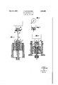
The present invention overcomes this disadvantage and does so by detachably connecting to the press pot the closure member of the press pot which acts as a guide for the perforating mandrel; By this connection of the closure member to the press pot, the closure member acts as a stripper for the pressed tube when the mandrel is withdrawn from the press pot. c A construction example of the invention is diagrammatically illustrated in the Vaccom-v panying drawings in which Figure 1 shows the pressbefore the commencement of the perforation of the block.
Figure 2 shows the position of the various parts of the press after the pressing of the tube has been carried out.
`Figures 3 Aand 4 show details.
In the accompanying drawings 1 denotes the guide casing for the press pot 2, which in MIT BESCHRANKTER H/AFTUNG, 0F DUIS- METAL Ex'rnUsIoN PRESS 469,082, and in Germany August 24, 1929.
the present case can be moved up and down or to and fro, and into which extends the hollow stationary press ram 3, with the die 4 mounted upon it.` The open side'of the press pot remote from the press ram 3 is Vclosed by the cylindrical part or closure member 6 vprovided with handles 5. The closure member 6 is secured'to the container by a bayonet joint formed of the angular extensions 7 on the container 2 and of the grooves 8 on the closure part 6. After the former has been rotated through a certain angle it can be lifted oit' the press pot 2 for the purpose of inserting a block 9.I l The press piston 10 is provided at its end with a recess 11 intoy which the head 12 of the perforating mandrel 13 can beinserted. Bolts 14 projecting radially into the recess and diverging outwards serve to engage under the head -12 of the mandrel. Instead of the construction shown, the recess 11 may be non-circular (see Figures 3 and 4) so that if the head of the mandrel be.corre spondingly shaped, this head after it has been 'inserted into the recess 11 will be carried along when the press piston 1 0 Vrecedes, .and can be detached again by turning it.
1 The operation of the apparatusv is as folows:-
After the imperforate block 9 has been I placed on the press ram 3, the closure member 6 having been lifted off, the closure member with the mandrel advantageously inserted therein may be again applied in position` and by turning, it is connected to the press pot, whereupon commences the operative movement of the press piston 10. This brings the head 12 of the mandrel 13 into the recess 11 in the press piston. At the same time the bolts 14 which at rst when the head 12 entered are splayed apart engage under this latter. The press piston 10 as it moves onward now forces the mandrel through the block 9, until its front end penetratesv the die 4. The press piston 10 as it`moves onward is now carried along with the press pot also, where' by the press ram 3 penetrates the press pot and the formation of the tube proceeds. The tube being formed passes as it lis formed.
throu h thel press ram 3 and out of it.
In igure 2 the-positions of the press piston, the ram and the press pot for the block, are shown in the end potion after the press- Y ing operation has been completed. The piston 10 is now again drawn back and the man- 5 drel 13 is carried with it and thus withdrawn 'irom thedtglbe formed. he work 1iltsel 'is supporte yitswasteen againstt einner end of the closure member 6 and this latter acts therefore -as a stripper of the tube from 10 the mandrel 13. Thereupon the closure member6 can be lifted off the presspot by turning it through a certain angle and the mandrel 13 removed, so that a :Eresh block can be inserted and the cycle of operations can take 15 place again in the manner described.
I claim:
A tube extrusion press comprising a press pot, a hollow press ram co-axial with said press pot, the press pot and ram being relatively movable, a die supported by the ram, a press piston (zo-axially movable in relation to l the ram, a co-axial mandrel supported bythe said press piston and serving for the preliminary perforation of a block of work contained in the press pot, a closure member for said ress pot which acts as a l'de for the man rel and which closure mem v ris detachably connected to the said press pot, and means for engaging said closure member with 3o said press pot.
OSWIG SCHLENSTEDT.
Applications Claiming Priority (1)
| Application Number | Priority Date | Filing Date | Title |
|---|---|---|---|
| DE1859990X | 1929-08-24 |
Publications (1)
| Publication Number | Publication Date |
|---|---|
| US1859990A true US1859990A (en) | 1932-05-24 |
Family
ID=7746437
Family Applications (1)
| Application Number | Title | Priority Date | Filing Date |
|---|---|---|---|
| US469082A Expired - Lifetime US1859990A (en) | 1929-08-24 | 1930-07-19 | Metal extrusion press |
Country Status (1)
| Country | Link |
|---|---|
| US (1) | US1859990A (en) |
Cited By (8)
| Publication number | Priority date | Publication date | Assignee | Title |
|---|---|---|---|---|
| US2913107A (en) * | 1954-11-24 | 1959-11-17 | Biginelli Oreste Flavi Alfredo | Extrusion press for indirect extrusion of hollow parts |
| US2929499A (en) * | 1956-11-01 | 1960-03-22 | United Wire & Supply Corp | Mandrel manipulation apparatus |
| US2941240A (en) * | 1956-05-10 | 1960-06-21 | Jennings Machine Corp | Apparatus for extruding tubing of polytetrafluoroethylene |
| US3074549A (en) * | 1959-12-29 | 1963-01-22 | Baldwin Lima Hamilton Corp | Tool assembly for a metal working press |
| US3381512A (en) * | 1964-08-07 | 1968-05-07 | Lindemann Maschfab Gmbh | Hydraulic extrusion press |
| US3404552A (en) * | 1965-05-17 | 1968-10-08 | Reynolds Metals Co | Billet piercing and extrusion |
| US3411337A (en) * | 1966-10-14 | 1968-11-19 | Reynolds Metals Co | Apparatus for extruding metal tubing |
| US3528275A (en) * | 1965-11-11 | 1970-09-15 | Demag Ag | Method and apparatus for extruding hollow articles |
-
1930
- 1930-07-19 US US469082A patent/US1859990A/en not_active Expired - Lifetime
Cited By (8)
| Publication number | Priority date | Publication date | Assignee | Title |
|---|---|---|---|---|
| US2913107A (en) * | 1954-11-24 | 1959-11-17 | Biginelli Oreste Flavi Alfredo | Extrusion press for indirect extrusion of hollow parts |
| US2941240A (en) * | 1956-05-10 | 1960-06-21 | Jennings Machine Corp | Apparatus for extruding tubing of polytetrafluoroethylene |
| US2929499A (en) * | 1956-11-01 | 1960-03-22 | United Wire & Supply Corp | Mandrel manipulation apparatus |
| US3074549A (en) * | 1959-12-29 | 1963-01-22 | Baldwin Lima Hamilton Corp | Tool assembly for a metal working press |
| US3381512A (en) * | 1964-08-07 | 1968-05-07 | Lindemann Maschfab Gmbh | Hydraulic extrusion press |
| US3404552A (en) * | 1965-05-17 | 1968-10-08 | Reynolds Metals Co | Billet piercing and extrusion |
| US3528275A (en) * | 1965-11-11 | 1970-09-15 | Demag Ag | Method and apparatus for extruding hollow articles |
| US3411337A (en) * | 1966-10-14 | 1968-11-19 | Reynolds Metals Co | Apparatus for extruding metal tubing |
Similar Documents
| Publication | Publication Date | Title |
|---|---|---|
| US3402591A (en) | Apparatus for making drawn and ironed cans or containers | |
| US1859990A (en) | Metal extrusion press | |
| GB836706A (en) | Improvements relating to the production of hollow metal bodies by pressing | |
| US3312098A (en) | Apparatus for forming cup-shaped members | |
| US2778494A (en) | Extrusion apparatus for thin-walled hollow tubing | |
| US2861335A (en) | Method of forming a hollow box in a metal wall | |
| GB951041A (en) | Tube-bending machine | |
| US1955243A (en) | Method of producing seamless tubes by extrusion | |
| GB1162355A (en) | Punching Holes in Elongated Bodies | |
| US3036696A (en) | Method of producing seamless tubular articles | |
| US2225710A (en) | Die for stamping tapered tubiform elements | |
| GB629573A (en) | Hydraulic press for extruding metal | |
| US1934292A (en) | Process and machine for threading the necks of tubes | |
| US2052738A (en) | Vertical hydraulic tube extrusion press | |
| US1802785A (en) | Method of extruding long seamless tubing | |
| US1521065A (en) | Apparatus for manufacturing metal sheets and strips | |
| US130758A (en) | somers | |
| SU523735A1 (en) | The method of separating the tube with internal fins from the forming edge of the needle section | |
| RU2062675C1 (en) | Die set for extruding tubes | |
| DE730486C (en) | Method for producing blocks which are further processed by hollow pressing, in particular those for pressing internal combustion engine pistons | |
| SU412963A1 (en) | ||
| GB190926013A (en) | Improvements in and relating to Hydraulic Squirting Presses. | |
| SU473539A1 (en) | Pipe pressing tool | |
| GB647479A (en) | Improvements in or relating to extruded tubing and methods and apparatus for the production thereof | |
| SU1037991A1 (en) | Tool for prepress broaching of blanks |