US1851616A - Screen - Google Patents
Screen Download PDFInfo
- Publication number
- US1851616A US1851616A US465437A US46543730A US1851616A US 1851616 A US1851616 A US 1851616A US 465437 A US465437 A US 465437A US 46543730 A US46543730 A US 46543730A US 1851616 A US1851616 A US 1851616A
- Authority
- US
- United States
- Prior art keywords
- screen
- roller
- cables
- sheaves
- trained
- Prior art date
- Legal status (The legal status is an assumption and is not a legal conclusion. Google has not performed a legal analysis and makes no representation as to the accuracy of the status listed.)
- Expired - Lifetime
Links
Images


Classifications
-
- E—FIXED CONSTRUCTIONS
- E06—DOORS, WINDOWS, SHUTTERS, OR ROLLER BLINDS IN GENERAL; LADDERS
- E06B—FIXED OR MOVABLE CLOSURES FOR OPENINGS IN BUILDINGS, VEHICLES, FENCES OR LIKE ENCLOSURES IN GENERAL, e.g. DOORS, WINDOWS, BLINDS, GATES
- E06B9/00—Screening or protective devices for wall or similar openings, with or without operating or securing mechanisms; Closures of similar construction
- E06B9/56—Operating, guiding or securing devices or arrangements for roll-type closures; Spring drums; Tape drums; Counterweighting arrangements therefor
- E06B9/68—Operating devices or mechanisms, e.g. with electric drive
-
- E—FIXED CONSTRUCTIONS
- E06—DOORS, WINDOWS, SHUTTERS, OR ROLLER BLINDS IN GENERAL; LADDERS
- E06B—FIXED OR MOVABLE CLOSURES FOR OPENINGS IN BUILDINGS, VEHICLES, FENCES OR LIKE ENCLOSURES IN GENERAL, e.g. DOORS, WINDOWS, BLINDS, GATES
- E06B9/00—Screening or protective devices for wall or similar openings, with or without operating or securing mechanisms; Closures of similar construction
- E06B9/56—Operating, guiding or securing devices or arrangements for roll-type closures; Spring drums; Tape drums; Counterweighting arrangements therefor
- E06B9/58—Guiding devices
Definitions
- Fig. 6 is av section taken on line'Gf-Gof particularly to roller screens for windows, or Fig. 5.
- Fig. 7 is a section taken on line 7 7 of A primary object of the invention is to pro- Fig. 1.
- Fig. 8 is an elevation of a window screen g55 of the character described. which embodies another ⁇ form of the inven- Another primary obj ect of the invention is tion,r the view being taken looking'iromy the to provide improved means for mounting the inside of the window frame.
- f 4 'i roller of the screen so that it may be rela V Fig.
- FIG. 9 is an enlarged section takenon line tively long to permit the use of a screen near- 9,-9 of Fig. 8,l and f l Q ly as wide as the window opening.
- Figyl() isanl enlarged section taken on4 line
- One form of the invention is embodied '1D-'10 of Fig. 8.
- v j 'Y in a window screen comprising aroller ro- Referring to the drawings, wherein I have tatably mounted in the upper end ofy the winshown a.
- ein-V ,lJ dow frame a screen or mesh trained over bodied in a roller screen for a1windo ⁇ w, the s A' the roller so that both ends of the screen may screen proper or mesh is designated by the be alined with each other when the screen is reference character 10, 'and is trained over a not in use; sheaves or pulleys mounted in the roller 11 mounted in the upper end of a winlower ends of the window traine; ⁇ cables at- ⁇ dow frame 12.
- ⁇ Cables 13 and v14 have their I tached to the ends of the screen'and trained ends attached to the ends ofthe screen or y70 i over the sheaves or pulleys; and turnbuckles mesh and are trained vover sheaves or in the cables for tensioning the screen longi* pulleys 15 and 16, respectively, which are rotudinally.
- the roller 11 is preferably tubular in form. 75
- FIG. 1 Another form 'of the invention is embodied 21S best llustratedin Figs. 3 and A plug 19 in window screen construction in substantial- 1 rigidly secured in one end of the roller 11 ly the same manner as that construction deyis provided with a project-ing pin ⁇ 20 rotatascribed above but arranged so that the cables bly journaled in an apertured disk 21 secured are 001109211611 llliglllde m'embels lll Which the t() Window frame Screws 2277.01-
- a plug 23 is rigidly .secured in Many Othef Obleete elle advantages W1 the otherend ol'theroller ⁇ 11.
- the plug 23 a'PPee aethle deeelpten Progfeesesv refer" being spacedfrom'that'end ofthe roller, as ence bemg had to the aecompanymg draw shown in Fig. 3. Projecting outwardly from ings wherein: i the plufr 23 is a pin 24 which is rotatablv 85 Figure l ,is .an elevation @.f a Window Screen" j ournaled ina U-shaped bearing bracket 25.
- FIG. 3 is an enlarged vertical longitudinal Sectiontaken through the upper end of the screcnand the means for rotatably journaling i.; it, the roller being shown partly in elevalese in Width than the Width OfitherWildOW tion j opening.
- u U 0 Y Fig. 4 is a Section taken 0n line 1 -,.4 of The roller 11 Isprovided withaslot or notch Fig. 3. 28 adjacent the plug 23 so that the roller may Fig. 5 is a Section taken on line 5-5 of be mounted between the members 21 and26,
- each sheet metalguide 31 comprises integral flanges 34 and 35 'proj ectin'g'inwards from the-sides Yof the ⁇ Win-dow opening, the flanges v35beingbent'to provide a bracket portion 36 through Which the screws v 32 project.
- a Yreinforcing rbar 239 is ;.pro,vided atf'eachV end of the screen or mesh 10.
- Fmch reinforcing-,bar-BQ is fpre'ferawhich is also formed fromfsheet imetal rand ,comprises anges -42 ande3, the flanges 42 and V4,3 being adaptedV to clampatheendofthe n'screen -between jrther'n Iand the langes of ithe anglefmember 40.
- y Rivets 44 preferably sel.cure "the flange D42 to A ⁇ the .angle member A'40, v
- the imember;.41 alsopreferably Y,comprises :a ,Hangesi forming anextension of .thexflange .bcrf .This construction.
- the ⁇ space betweenfithe ,relier ,11 .and the ripper.crossnnember-of tlie fname 12 may be closed by an Vangle iron 47, or the equivalent.
- Apparatus 'of 'the :kind idescribedzcomi prising fa roller., :a iscreen vitrained y'over the roller, sheaves, cables attached to the vends .of the screen and rtrained .over vthe .1sheaves, y'and kturnbuckles :in .the cables -lforttensiioning ⁇ the SCITEGIL means trained over Ythe sheaves ...and attached :to the rends of the screen.
- Apparatus ott the kind described ⁇ "com- .l v vprisin'g a iroller, 'la yscreen :trained over AtheY froller, sheaves, ⁇ and lcables includingtension Infarollerscreen,;airollerhavingarnotch -in onefend Pthereo'f l'and .provided vwith a lpi'n in said end, substantially the-entire VFlength odi' said pinfb'eing'With-ifn said roller, a bearing bracket ⁇ :tor jvournallfing Esaid fpin, said V-bearing kbra'cket 'being adapted kLto ⁇ pass through saidnotchrwhen said rollerfis being Y :assembled with said bracket, and'meansfor rotatably journalling the other 'end of ⁇ the roller.V I A Y 4.
- Apparatus of the kind described comprising a rotatably ournaled roller, a screen trained over said roller, cables attached to both ends of the screen, means constrained to move With the cables for tensioning the screen sheaves over Which said cables are trained, and guide members for the side edges of said screen, said guide members forming housings for said cables.
- Apparatus of the kind described comprising a rotatably ournaled roller, a screen trained over said roller, cables attached to both ends of the screen, means carried by the cables for tensioning them, sheaves over which said cables are trained, and guide members for the side edges of ⁇ said screen, said guide members Vorming housings for said cables.
- Apparatus of the kind described comprising a rotatably journaled roller, a screen trained over said roller, cables attached to both ends of the screen, turn-buckles for vtensioning said cables, sheaves over which said cables are trained, and guide members for the side edges of said screen, said guide-members forming housings for said cables.
- Apparatus of the kind described comprising a roller, a screen trained over the roller, cables attached to the ends of said screen, and turn-buckles secured to said cables for tensioning the screen.
Landscapes
- Engineering & Computer Science (AREA)
- Structural Engineering (AREA)
- Architecture (AREA)
- Civil Engineering (AREA)
- Overhead Projectors And Projection Screens (AREA)
- Operating, Guiding And Securing Of Roll- Type Closing Members (AREA)
- Displays For Variable Information Using Movable Means (AREA)
Description
March 29, 1932; C, BOCK 4 1,851,616
SCREEN l Filed July 2, 195o :s sheets-sheet 1 m 2 -d//l47 March 29, 193.2.
c: BocK 1,851,616
SCREEN Filed July 2, 1930 3 Sheets-Sheet 2 'i Br-WMM 44 l A 40/ LW w@ I 56' [i J5 [J March 29, 1932. c. B'OCK SCREEN Filed July 2, .9
5 Sheets-Sheet 5 PatentedMar.z9,1932 I l i l `1,851,616
' UNITED STATES PATENT CHARLES BOCH, or CHICAGO, ILLINOIS, AsSIGNoH To ANDREW` HorrIvIAN MFG. C0.,
or CHICAGO, ILLINCIS, A CORPORATION on ILLINOIS f SCZREE'BTV Application led July 2, 1930.y Serial No..465,437.
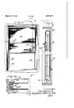
The invention relates to screens, and more Fig. 6 is av section taken on line'Gf-Gof particularly to roller screens for windows, or Fig. 5. y 'y the like. Fig. 7 isa section taken on line 7 7 of A primary object of the invention is to pro- Fig. 1. I vide improved means for tensioning a screen Fig. 8 is an elevation of a window screen g55 of the character described. which embodies another `form of the inven- Another primary obj ect of the invention is tion,r the view being taken looking'iromy the to provide improved means for mounting the inside of the window frame. f 4 'i roller of the screen so that it may be rela V Fig. 9 is an enlarged section takenon line tively long to permit the use of a screen near- 9,-9 of Fig. 8,l and f l Q ly as wide as the window opening. 1 Figyl() isanl enlarged section taken on4 line One form of the invention is embodied '1D-'10 of Fig. 8. v j 'Y in a window screen comprising aroller ro- Referring to the drawings, wherein I have tatably mounted in the upper end ofy the winshown a. preferred form of the invention ein-V ,lJ dow frame; a screen or mesh trained over bodied in a roller screen for a1windo`w, the s A' the roller so that both ends of the screen may screen proper or mesh is designated by the be alined with each other when the screen is reference character 10, 'and is trained over a not in use; sheaves or pulleys mounted in the roller 11 mounted in the upper end of a winlower ends of the window traine;` cables at- `dow frame 12. `Cables 13 and v14 have their I tached to the ends of the screen'and trained ends attached to the ends ofthe screen or y70 i over the sheaves or pulleys; and turnbuckles mesh and are trained vover sheaves or in the cables for tensioning the screen longi* pulleys 15 and 16, respectively, which are rotudinally. Improved means for journaling tatably journaled in brackets 17 mounted in the roller so that the screen may be nearly the lowerend ofthe frame 12.
...-5. as Wide as the window opening. The roller 11 is preferably tubular in form. 75
j Another form 'of the invention is embodied 21S best llustratedin Figs. 3 and A plug 19 in window screen construction in substantial- 1 rigidly secured in one end of the roller 11 ly the same manner as that construction deyis provided with a project-ing pin `20 rotatascribed above but arranged so that the cables bly journaled in an apertured disk 21 secured are 001109211611 llliglllde m'embels lll Which the t() Window frame Screws 2277.01-
eide edges 0f the s efeei 01 mesh ride equivalent. A plug 23 is rigidly .secured in Many Othef Obleete elle advantages W1 the otherend ol'theroller` 11. the plug 23 a'PPee aethle deeelpten Progfeesesv refer" being spacedfrom'that'end ofthe roller, as ence bemg had to the aecompanymg draw shown in Fig. 3. Projecting outwardly from ings wherein: i the plufr 23 is a pin 24 which is rotatablv 85 Figure l ,is .an elevation @.f a Window Screen" j ournaled ina U-shaped bearing bracket 25. menaienteinen; einer preferably formed We a disk 2@ j ing-from thev inside of the window frame. Cue ,Eg hhwuldogl .fragile 12'd tglljlte y.. Fig. 2 is an enlarged section taken onV line no e ,e pm 1S lspose W1 m e 90 Q Q of Fg'l roller 11 and that the `length ,of the roller 11 is nearly equal'to the 'width of thewindow f opening. rThis construction permits the use of ascreen or mesh10 which is only slightly Fig. 3 is an enlarged vertical longitudinal Sectiontaken through the upper end of the screcnand the means for rotatably journaling i.; it, the roller being shown partly in elevalese in Width than the Width OfitherWildOW tion j opening. u U 0 Y Fig. 4 is a Section taken 0n line 1 -,.4 of The roller 11 Isprovided withaslot or notch Fig. 3. 28 adjacent the plug 23 so that the roller may Fig. 5 is a Section taken on line 5-5 of be mounted between the members 21 and26,
.zo Fig. 2. or removed from between them by passing 100 VV 2o bly fabricated :from `anangle member y40- Y formedi-from 'sheetmetalfanda member 41,
' the bearing member 25 through the slot or notch 28. y
As best shown in Fig. 7, the side edges of the screen or mesh 10 ride in grooves 30 formed in sheet metal members 31 which are rigidlycsecuredgto ithe frame 4V12 by screws 32, or the-equivalent.
It will be noted that each sheet metalguide 31 comprises integral flanges 34 and 35 'proj ectin'g'inwards from the-sides Yof the `Win-dow opening, the flanges v35beingbent'to provide a bracket portion 36 through Which the screws v 32 project. e
` At each ofthe four corners ofthescreenor mesh 10, a substantially U-shaped metallic clipf38fis:providedathe clipsf3-8 being.- adapted to ride in the slots or grooves 30 (see Righi).
. A Yreinforcing rbar 239 is ;.pro,vided atf'eachV end of the screen or mesh 10. (See Figs. 2 V-andti.) ,Fmch reinforcing-,bar-BQ is fpre'ferawhich is also formed fromfsheet imetal rand ,comprises anges -42 ande3, the flanges 42 and V4,3 being adaptedV to clampatheendofthe n'screen -between jrther'n Iand the langes of ithe anglefmember 40.y Rivets 44 preferably sel.cure "the flange D42 to A`the .angle member A'40, v The imember;.41alsopreferably Y,comprises :a ,Hangesi forming anextension of .thexflange .bcrf .This construction. isemployeditogive a neat ffnished appearance .to -thereirrorcing .bainv l Y -.U-shaped .clips 38 #preferably prdject'into .the -space between the vflanges .42 fand :the .angle .memberr40- vThe cables 13 :and14are .preferably tsecured u.togthe reinforcing .bars 39V instead of .fdireetlyto theendsofathe screenvorfmesh 10.
` `lurnhuckles 46 provided in the cables land 14 lbe manipulated to tension thescreen K -so that litY will .not buckle when Ait is drawn up or down'. It W'i'll'be readily Vunderstood that this Vconstruction fis exceedingly advantageous as. lany slack in lth'e screen resulting 'from continued use thereof -may'be'taken up. 'With such 'constructiomfthe tW'ideiedges of jthe screen W'ill not tend to 7Work 'out off't'he 'slots Yor grooves V30 and'thescreen Will'have-a neaftl `appearance at 'afl'lftimes Y `When the screen is rin suse,-rthe 'lower fend thereof may `be pushed upwards ifuntil j-t .is 'alined with the .upper `:edge 'thereof which l @moves downward Iwhen "the vupper fedge is moved upward. 'The screen will then only cover the `upper :balai -of the Window opening.
The `space betweenfithe ,relier ,11 .and the ripper.crossnnember-of tlie fname 12 may be closed by an Vangle iron 47, or the equivalent.
:Referring now to :Figs 8 to 1.0, inclusive, wherein Tlf l.have shown kanother preferred `form of `theinvent-icm the screen proper or ,mesh is designatedby the reference character V and is trained over a roller "61 mounted in :sheet metalguide members 72 vertically disposed in the frame 62 and secured thereinwardly'. extending 'flanges .f73betweenwvhich the side edges of the mesh 60 project, -the space Within1the;guidermenibers62 being rel- :atively large'to accommodate fcables .64 :and
65 which also travelifmtliegrooves f? 'llind'ow screens :embodying this form of fthe .inventioniare neat and :attractive :as'the cables/are-znotiexp'ose.d.
Y /Vhileihave shown and idisscribed certain embodiments :of Vmy finvention, it is ,to tbe :un-
. dersteod that it is `capable iof l.many modifications." Glianges, itlierefore, :in 7the construction fandarrangement .may be made Without departing strom the fspirit and ,scope .fofthe liirventionzasidisclosediin'theappen-ded claims,
ziniwhich )it 'is fmyv intention to claim Tall `aiovfeltyrinherent iin invention `fas broadly :as
Asshowniin Fig..the'inneriendsofzthe posslble mime, o hepmol' i :What -I regardfas zn'ew, and .desire 1to secirre 'fby Letters Rai-tennis:
f1. Apparatus 'of 'the :kind idescribedzcomi ,prising fa roller., :a iscreen vitrained y'over the roller, sheaves, cables attached to the vends .of the screen and rtrained .over vthe .1sheaves, y'and kturnbuckles :in .the cables -lforttensiioning `the SCITEGIL means trained over Ythe sheaves ...and attached :to the rends of the screen.
f2. Apparatus :ott the kind described `"com- .l v vprisin'g a iroller, 'la yscreen :trained over AtheY froller, sheaves, `and lcables includingtension Infarollerscreen,;airollerhavingarnotch -in onefend Pthereo'f l'and .provided vwith a lpi'n in said end, substantially the-entire VFlength odi' said pinfb'eing'With-ifn said roller, a bearing bracket `:tor jvournallfing Esaid fpin, said V-bearing kbra'cket 'being adapted kLto `pass through saidnotchrwhen said rollerfis being Y :assembled with said bracket, and'meansfor rotatably journalling the other 'end of `the roller.V I A Y 4. 'Apparatus of vthe hind vdeseribeiil comfnisingorotatably journaledflroller, a-recitan'gular screen trained over said Vroller, clip members secured to the corners of the screen, reinforcing barsextendingfb'etween fthe clips, sheaves, cables trained over the sheavesIand 'attached to said ibars, and'meansor tensioning the screen longitudinally.l
5. Apparatus of the kind described comprising a rotatably ournaled roller, a screen trained over said roller, cables attached to both ends of the screen, means constrained to move With the cables for tensioning the screen sheaves over Which said cables are trained, and guide members for the side edges of said screen, said guide members forming housings for said cables.
6. Apparatus of the kind described comprising a rotatably ournaled roller, a screen trained over said roller, cables attached to both ends of the screen, means carried by the cables for tensioning them, sheaves over which said cables are trained, and guide members for the side edges of `said screen, said guide members Vorming housings for said cables.
7 Apparatus of the kind described comprising a rotatably journaled roller, a screen trained over said roller, cables attached to both ends of the screen, turn-buckles for vtensioning said cables, sheaves over which said cables are trained, and guide members for the side edges of said screen, said guide-members forming housings for said cables.
8. Apparatus of the kind described comprising a roller, a screen trained over the roller, cables attached to the ends of said screen, and turn-buckles secured to said cables for tensioning the screen. Y
In witness whereof, I hereunto aiX my signature, this 20th day 'of June,'1930.
CHARLES BOCK.
Priority Applications (1)
| Application Number | Priority Date | Filing Date | Title |
|---|---|---|---|
| US465437A US1851616A (en) | 1930-07-02 | 1930-07-02 | Screen |
Applications Claiming Priority (1)
| Application Number | Priority Date | Filing Date | Title |
|---|---|---|---|
| US465437A US1851616A (en) | 1930-07-02 | 1930-07-02 | Screen |
Publications (1)
| Publication Number | Publication Date |
|---|---|
| US1851616A true US1851616A (en) | 1932-03-29 |
Family
ID=23847804
Family Applications (1)
| Application Number | Title | Priority Date | Filing Date |
|---|---|---|---|
| US465437A Expired - Lifetime US1851616A (en) | 1930-07-02 | 1930-07-02 | Screen |
Country Status (1)
| Country | Link |
|---|---|
| US (1) | US1851616A (en) |
-
1930
- 1930-07-02 US US465437A patent/US1851616A/en not_active Expired - Lifetime
Similar Documents
| Publication | Publication Date | Title |
|---|---|---|
| EP0363454B1 (en) | Covering for masking an opening | |
| EP0377778A1 (en) | Louver blind with vertical louver slats | |
| DE112014004253T5 (en) | Insect slider grille installation structure comprising a rail frame with a removable segment structure | |
| US1851616A (en) | Screen | |
| EP0254896A2 (en) | Roll-screen for mobil-home window | |
| DE102004003067B4 (en) | Device for connecting a roller blind to a winding shaft | |
| DE2501147C3 (en) | Gatherable slat blinds | |
| EP1167680A2 (en) | Suspension springs for roller shutter | |
| CH150758A (en) | Equipment for the demonstration of interchangeable advertisements for daylight and night advertising. | |
| DE2407116C2 (en) | Gatherable slat blinds | |
| DE69912967T2 (en) | WINDOW BLINDS FOR DECORATION AND SUN PROTECTION | |
| DE2238177C3 (en) | Gatherable slat blinds | |
| US1355608A (en) | Screen, curtain, and the like | |
| DE1207826B (en) | Automatic clamping device for a pull cord of slat blinds or the like. | |
| DE202011000025U1 (en) | Anti-glare blinds | |
| AT129893B (en) | Showcase for X-ray images. | |
| DE1683248A1 (en) | Lamellar curtain | |
| AT241781B (en) | Roller curtain | |
| DE85535C (en) | ||
| FI70623B (en) | SPEED MECHANISM | |
| DE20319143U1 (en) | Vertical or Venetian blind has slats made up of three strips, cord being fastened to central strip to adjust its inclination and side strips being more translucent than central strip. | |
| DE69804168T2 (en) | Arrangement of poster boxes | |
| DE19706192B4 (en) | Device for shading window or door openings or for cladding machines u. like. | |
| DE478424C (en) | Device for simulating the change in the appearance of a display area | |
| DE202006017200U1 (en) | shutters |