US1851562A - Wrench - Google Patents
Wrench Download PDFInfo
- Publication number
- US1851562A US1851562A US542301A US54230131A US1851562A US 1851562 A US1851562 A US 1851562A US 542301 A US542301 A US 542301A US 54230131 A US54230131 A US 54230131A US 1851562 A US1851562 A US 1851562A
- Authority
- US
- United States
- Prior art keywords
- shank
- sleeve
- wrench
- jaw
- teeth
- Prior art date
- Legal status (The legal status is an assumption and is not a legal conclusion. Google has not performed a legal analysis and makes no representation as to the accuracy of the status listed.)
- Expired - Lifetime
Links
- 208000012260 Accidental injury Diseases 0.000 description 2
- 208000014674 injury Diseases 0.000 description 2
- 238000010276 construction Methods 0.000 description 1
- 238000004519 manufacturing process Methods 0.000 description 1
- 235000013372 meat Nutrition 0.000 description 1
- 210000003813 thumb Anatomy 0.000 description 1
Images
Classifications
-
- B—PERFORMING OPERATIONS; TRANSPORTING
- B25—HAND TOOLS; PORTABLE POWER-DRIVEN TOOLS; MANIPULATORS
- B25B—TOOLS OR BENCH DEVICES NOT OTHERWISE PROVIDED FOR, FOR FASTENING, CONNECTING, DISENGAGING OR HOLDING
- B25B13/00—Spanners; Wrenches
- B25B13/10—Spanners; Wrenches with adjustable jaws
- B25B13/12—Spanners; Wrenches with adjustable jaws the jaws being slidable
- B25B13/14—Spanners; Wrenches with adjustable jaws the jaws being slidable by rack and pinion, worm or gear
Definitions
- An object of this-invention is to provide a from the fixed jaw being limitedby the -stop wrench of the quick adjusting type which is of simple and durable construction, econom- 1 ical" to manufacture, and 'which may be quickly and conveniently adjusted. Another object is to provide a Wrench designedto minimize the danger of accidental disengagement of the movableja-w from its adjusted or locked position, and further to pro vide means affording a protection against accidental injury to the spring mechanism which normally holds the movable jaw in locked or adjusted position.
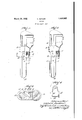
- Fig. 1 is a side elevation of the wrench with the movable jaw in operative position
- Fig. 2 is a view similar to Fig. 1 showing the movable jaw moved from its operative Fig. 3 3-3 of Fig. 1';
- Fig. 4 is acomposite view of the spr ng .member.
- the improved wrench shown therein comprises a shank 10 having a ribbed portion 11 providing a longitudinally extending abutment, and a fixed jaw 12 integral with one end of the shank.
- the sleeve 18 slidably mounted on the shank 10 is integral with the movablejaw 14: and carries theworm or thumb screw 15 which engages the teeth 16 on the shank.
- sleeve is provided with a flaring opening or bore, as shown in Figs. 1 and 3, which permits a rocking movement on the shank todisengage the worm 15 from the teeth 16 thereby permitting the sleeve to be moved 5 freely along the shank, its movement away is an enlarged section on the line pin 17.
- the sleeve is provided with an opening18' and a slot 19 adjacent to the rib ll of the shank.
- the benteup end 21 of the U-shaped 5o spring is anchored in opening. 18 and its opposite end 22,.disposed in slot 19, yield- "ingly'engages the rib llfirrespective of the.
- the wrench herein shown and described is free from projecting parts and consequentlythe danger of accidental disengagement of the movable jaw from its locked or adjusted position isgreatl 7 1y minimized.
- the spring member 20 being housed between the sleeve and shank is afforded a substantial protection against accidental injury.
- the springfQO is of such simple an'detiicient design that itmay be manufactured economically, assembled with facility and, in emergency, replaced by an-improvised spring. r
- v v 1 A wrenchof the character described comprising a shank having teeth on' one of its longitudinal edges, a fixed-jaw integral with one end of the shank, a longitudinally exi tending abutment on saidshank, sleeve slidably mounted on said shank andpro- Q vided with an opening and a slottedp'on. l tion adjacent to said abutment, a movable I 1 jaw integral with said sleeve, a worm car- I ried by the sleeve and engageable with the 9,
- said sleeve having a rocking mQVementon said shank to' disengage the Worm from the teeth therebyto permitthe sleeve to be moved longitudinally of said shank, and means normally wholding thewonn and teeth in operative engagement, said means comprising a U-shaped spring having bent-11p end portions, one of said ends being anchored in the opening in said sleeve andthe other end disposed in said slot and yielding-1y engaging saidabutment vlrrespect ve of the relative 13051 61011 ofxsmd sleei e andshank.
Landscapes
- Engineering & Computer Science (AREA)
- Mechanical Engineering (AREA)
- Details Of Spanners, Wrenches, And Screw Drivers And Accessories (AREA)
Description
- March 29, 1932. BUTLER 1,851,562
WRENCH Filed June 5, 1931 V J II/l I 70 Z-;w27zZ07 Z0697? fiZdZZe 7 Patented Mar. 29, 1932: i
UNITED STATES PATENT OF 'Ep ROBERT BUTLER, or nosroinivrnssnonusnrrs Wanner: Applicationfiled June; 5, 1931. Serial No. 542,301."
An object of this-invention is to provide a from the fixed jaw being limitedby the -stop wrench of the quick adjusting type which is of simple and durable construction, econom- 1 ical" to manufacture, and 'which may be quickly and conveniently adjusted. Another object is to provide a Wrench designedto minimize the danger of accidental disengagement of the movableja-w from its adjusted or locked position, and further to pro vide means affording a protection against accidental injury to the spring mechanism which normally holds the movable jaw in locked or adjusted position.
; positlon;
Further ob'eots and advantages will be apparent from a consideration of the following description and accompanying drawings which exemplify one embodiment of this invention chosen for the purpose of illustration.
In the drawings:
Fig. 1 is a side elevation of the wrench with the movable jaw in operative position;
Fig. 2 is a view similar to Fig. 1 showing the movable jaw moved from its operative Fig. 3 3-3 of Fig. 1'; and
Fig. 4 is acomposite view of the spr ng .member.
' Referring tothe drawings, the improved wrench shown therein comprises a shank 10 having a ribbed portion 11 providing a longitudinally extending abutment, and a fixed jaw 12 integral with one end of the shank. The sleeve 18 slidably mounted on the shank 10 is integral with the movablejaw 14: and carries theworm or thumb screw 15 which engages the teeth 16 on the shank. The
, sleeve is provided with a flaring opening or bore, as shown in Figs. 1 and 3, which permits a rocking movement on the shank todisengage the worm 15 from the teeth 16 thereby permitting the sleeve to be moved 5 freely along the shank, its movement away is an enlarged section on the line pin 17. 1
The sleeve is provided with an opening18' and a slot 19 adjacent to the rib ll of the shank. The benteup end 21 of the U-shaped 5o spring is anchored in opening. 18 and its opposite end 22,.disposed in slot 19, yield- "ingly'engages the rib llfirrespective of the.
relative position of the sleeve-and shankand normally holds the worm 15 in operativeen: x
able jaw in adjusted positionandpermitting 6;}
a fine adjustment from thatposition.
It willbe noted that the wrench herein shown and described is free from projecting parts and consequentlythe danger of accidental disengagement of the movable jaw from its locked or adjusted position isgreatl 7 1y minimized. Furthermore the spring member 20 being housed between the sleeve and shank is afforded a substantial protection against accidental injury. The springfQO is of such simple an'detiicient design that itmay be manufactured economically, assembled with facility and, in emergency, replaced by an-improvised spring. r
Iclaim; v v 1 A wrenchof the character described comprising a shank having teeth on' one of its longitudinal edges, a fixed-jaw integral with one end of the shank, a longitudinally exi tending abutment on saidshank, sleeve slidably mounted on said shank andpro- Q vided with an opening and a slottedp'on. l tion adjacent to said abutment, a movable I 1 jaw integral with said sleeve, a worm car- I ried by the sleeve and engageable with the 9,
this 3d day ofJnne, I931.
teeth on said shank, said sleeve having a rocking mQVementon said shank to' disengage the Worm from the teeth therebyto permitthe sleeve to be moved longitudinally of said shank, and means normally wholding thewonn and teeth in operative engagement, said means comprising a U-shaped spring having bent-11p end portions, one of said ends being anchored in the opening in said sleeve andthe other end disposed in said slot and yielding-1y engaging saidabutment vlrrespect ve of the relative 13051 61011 ofxsmd sleei e andshank.
Slgned by meat Boston, Massachusetts,
K0131 331 BUTLE'iij 'f f
Priority Applications (1)
| Application Number | Priority Date | Filing Date | Title |
|---|---|---|---|
| US542301A US1851562A (en) | 1931-06-05 | 1931-06-05 | Wrench |
Applications Claiming Priority (1)
| Application Number | Priority Date | Filing Date | Title |
|---|---|---|---|
| US542301A US1851562A (en) | 1931-06-05 | 1931-06-05 | Wrench |
Publications (1)
| Publication Number | Publication Date |
|---|---|
| US1851562A true US1851562A (en) | 1932-03-29 |
Family
ID=24163205
Family Applications (1)
| Application Number | Title | Priority Date | Filing Date |
|---|---|---|---|
| US542301A Expired - Lifetime US1851562A (en) | 1931-06-05 | 1931-06-05 | Wrench |
Country Status (1)
| Country | Link |
|---|---|
| US (1) | US1851562A (en) |
-
1931
- 1931-06-05 US US542301A patent/US1851562A/en not_active Expired - Lifetime
Similar Documents
| Publication | Publication Date | Title |
|---|---|---|
| US1851562A (en) | Wrench | |
| US1110220A (en) | Wrench. | |
| US1048298A (en) | Wrench. | |
| US1126678A (en) | Wrench. | |
| US1396981A (en) | Wrench | |
| US1428805A (en) | Wrench | |
| US1085198A (en) | Plier-wrench. | |
| US888338A (en) | Wrench. | |
| US952634A (en) | Monkey-wrench. | |
| US636673A (en) | Wrench. | |
| US1468415A (en) | Quick-adjusting wrench | |
| US1029944A (en) | Wrench. | |
| US2804793A (en) | Worm-latch means for a slidable side-jaw wrench | |
| US754137A (en) | Wrench. | |
| US1198243A (en) | Pipe-wrench. | |
| US1128983A (en) | Wrench. | |
| US1072283A (en) | Wrench. | |
| US838173A (en) | Wrench. | |
| US910961A (en) | Wrench. | |
| US887006A (en) | Wrench. | |
| US806497A (en) | Wrench. | |
| US1349852A (en) | Adjustable wrench | |
| US1166655A (en) | Wrench. | |
| US1114423A (en) | Wrench. | |
| US781515A (en) | Wrench. |