US1851336A - Incinerator - Google Patents
Incinerator Download PDFInfo
- Publication number
- US1851336A US1851336A US239273A US23927327A US1851336A US 1851336 A US1851336 A US 1851336A US 239273 A US239273 A US 239273A US 23927327 A US23927327 A US 23927327A US 1851336 A US1851336 A US 1851336A
- Authority
- US
- United States
- Prior art keywords
- hearth
- chamber
- grate
- combustion
- incinerator
- Prior art date
- Legal status (The legal status is an assumption and is not a legal conclusion. Google has not performed a legal analysis and makes no representation as to the accuracy of the status listed.)
- Expired - Lifetime
Links
Images
Classifications
-
- F—MECHANICAL ENGINEERING; LIGHTING; HEATING; WEAPONS; BLASTING
- F23—COMBUSTION APPARATUS; COMBUSTION PROCESSES
- F23G—CREMATION FURNACES; CONSUMING WASTE PRODUCTS BY COMBUSTION
- F23G5/00—Incineration of waste; Incinerator constructions; Details, accessories or control therefor
- F23G5/008—Incineration of waste; Incinerator constructions; Details, accessories or control therefor adapted for burning two or more kinds, e.g. liquid and solid, of waste being fed through separate inlets
Definitions
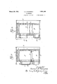
- Fig. 3 is a similarsectionV along the line i f VV
- the furnace" incinerator is I formed with front and rear walls l0, l1, respectively-,and
- a roof l2'isf provided, as is a suitable bottom or lbase 135'-Projecting upwardly from the bottom'lis a partition wall 14C between whichA and the end Wallsr 11 extends a gratefl overlying the ash pit 16.
- Inth'e side wall'lQ lnadditionto the clean- *n out openingl'? is ay charging opening QOflocatik ed abovefandv adjacentthegrate l5, asuitable door or other closure 2l being provided; -EX- 1 Jtending upwardly and forwardlyjfromthe l partition wall Mis; a'hearthQ preferably vof Y archedconstruction-andformed-ofrefractory 'f Y ioloeirs, ⁇ this heartli'leading to a vertical guard fw'all Qdi-also formed 'of refractory, 4and termiy ⁇ natinfgisome i distancey 'belowrzthelroofl 12. ⁇ A
- vaV 'n. ⁇ THoMPsom orA 1Nnw"YoRx, N.Y.', ⁇ AssIGNoRQBYyMnsNE.ssIeNMnnrs, To. MoRsE ..BoULGnnnnsrnuoron co., A CORPORATION; vor; DELAWARE 'baHeIwall'BQ resting uponthe'support32'y arch ⁇ and .extends between the side walls Y'18 posehhereinafter described. s also-pro- Vhearth25 and baiiie wall ⁇ 32. Y
- guard wallidipartition wall 14 end kwall yInV the operation of. mygimproved ator, the Y lighterfand more! combustible :ref-'S usevis charged upon theygrate 1,5, ⁇ and the; f
- 1Q vand bottomjil* form what Iterm a sec.y ondary cmbustionchamber, which, it will bey noted@ itylocateldvin large part' directly vbe-Y4 Y ineath the hearth Y25.
- This secondaryY com-V blustion chamber is likewise fof ample size, vparticular]yl'as contrasted with the crossfsec-V. tionalarea of ythe fines;3925 36.Y y i moist. and reluctantly combustible material; f
- the guard wellwiecreasng the f capacity of such hearth and preventing tumbling of refuse down through the duct 35.
- an incinei'ator having end, side and roof Walls, a grate located therein,vaii"inclined hearth also-located therein leading upward fromr one end of said grate, said hearth being provided with associated walls to forni a primary combustion chamber:overlying-*said hearth and grate and with a secondary combustion and settling ychamberdirectly underlying and in contact mith'isaidf'hearth, the latter forming alroof therefor, yandra ⁇ verticalwbaliie.
- said Yincinerator being further provided'with a primary combustion chamberof substan- /rtial volume overlyingsaid hearth and grate,
- an incincrator having end, side and roof walls,'a grate located therein, an yinclined hearth leading upward from one endof said grate also located therein, said incineratorbeing further provided with a primary conibiistioiichamber of silb- Staiitial volume overlying said hearth and ⁇ grate fand with a secondary combustion and settling chamber of substantial size directly underlying and in rContact with said. hearth,r
- an yincinerator having end, side and roof walls"q a grate located there-r in, an inclined hearth leading upward fromA one endr of said grate'also located therein,
- said incinerator being further provided with withA said hearth, the'latter' forming a roofi therefor, and ak vertical baffle wall spacedy i, fchamber.
- An incinerator comprising inf: combination a walled yenclosure having therein a grate n for burning dry 'combustibles,anupwardly,y inclined hearthhavingitsv lower ,endadjoiny y ing; one edge of said grate andleading upward therefrom Iandadapted to receive moist refuse, said' enclosure providing aY primary combustion space of substantial volumeabove .said grate and hearth, a secondary combusi tionchamber directly below andin ⁇ Contact with saidhearth having'a cross sectional area substantially as large as that of said primary space to permita ⁇ slow velocity'off ⁇ gases kthrough saidsecondary 'chambennnd a relat -in cross section as compared Vwith saidpri-k tively ,shortl passage substantially y restricted mary and secondary combustion ichambers andV leading downwardly from an ⁇ end of said,
Landscapes
- Engineering & Computer Science (AREA)
- Mechanical Engineering (AREA)
- General Engineering & Computer Science (AREA)
Description
March 29, 1932; s. H. THOMPSON INCINERATOR Filed Dec. i2, 1927 2 Sheets-sheet 1 March 29, 1932. s, H, THOMPSON l2. 1927 2 Sheets-Sheet 2 INCINERATOR Filed Dec.
"N1 MNB Patented i Mar. 29,1932
INCINEBA'rorL f I 'Application mea -necemberia i927; seria; No. 23,2713.
v This invention relates to'improvements in incinerators and has among its objects to provide a new andy improved apparatus comprisingV aY tgrate Vfor;relatively dry 'refuse A. and a hearthA for moistfrefus'e such as garbage or the like,=a primary "combustion chamber over-V lying the ygrate.andhe'arth and afsec'ond com- .bustion and settling chamber directlyjunderlying the hearth, all arranged with restricted lilies leading to'and from the .asecondcomf bustion chamber whereby acompachcicient n whichrf in` the embodiment illustrated is yian I' incinerator or refuse destructoris obtained with ample gas travel and settlingspace; Vand f one whichwill. conveniently and readily han- 5 dlewetfvand Idryirefuse in fair-'relative proportions.` s Y p, Y This applicationis in-part af'substitutlon formy application Serial blo-137,873: Y
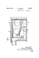
' These and other objects will'be morefully set forth anddescribed in the following speci-- f iication and illustrated inthe accompanying drawings, inwhichv Fig.'` l isa vertical longitudinal section-` 'through an inoinerator embodying my-invenu .tion;`y 'f f Fig. l2( `isa ltransverse verticalsection along the line 2 2 'of Fi,`g.1;andV i.
Fig. 3 is a similarsectionV along the line i f VV The furnace" incinerator is I formed with front and rear walls l0, l1, respectively-,and
Access may be had to the latter through an l opening 1'? for inspection or removal of ashes,l
Vcinde'rs orfthe like.
, Inth'e side wall'lQ lnadditionto the clean- *n out openingl'? is ay charging opening QOflocatik ed abovefandv adjacentthegrate l5, asuitable door or other closure 2l being provided; -EX- 1 Jtending upwardly and forwardlyjfromthe l partition wall Mis; a'hearthQ preferably vof Y archedconstruction-andformed-ofrefractory 'f Y ioloeirs,` this heartli'leading to a vertical guard fw'all Qdi-also formed 'of refractory, 4and termiy `natinfgisome i distancey 'belowrzthelroofl 12.` A
Glean-outopenings `337 l34,zu2e fvidedirgthe side wall- 19 andfare provided :with'suitable closures to permit ready access: to the interioro-the'incinerator beneathithe I charging opening 28is provided inV the side Y wall 19 above the hearth 25. vIt will be apf i parentthat thecharging openings 2O,v 28;;Inay
end terlninat-ing short llor" the bottomxl; but .below the/upper end yofthe hearth/2 5.; is vaV 'n.{THoMPsom orA=1Nnw"YoRx, N.Y.',`AssIGNoRQBYyMnsNE.ssIeNMnnrs, To. MoRsE ..BoULGnnnnsrnuoron co., A CORPORATION; vor; DELAWARE 'baHeIwall'BQ resting uponthe'support32'y arch `and .extends between the side walls Y'18 posehhereinafter described. s also-pro- Vhearth25 and baiiie wall`32. Y
v:Inv the embodimentshown, Vthe baffle wall?,
isfspacedasufiiciently.from theV guardiwall "2.6 5to`V` provide a flueV y35extemling substan# ftially 'crosstheffurnace kot"restricted'iarea, i i Y asrontrasted withthe combustion chambers, and this baffle 1wall32l is vsimilarly. located )with respect to 'thefront end y'wall 10 to pro-.S` vide ya second .'restrictedfiiue 36 which also extends substantiallycacross thefurnace and a f which leadstoy theoutlet chamber duct 38.` f i f It will bev apparent that in the structure described aboi'fe, the grate 15d.' hearthy 25,
guard wallidipartition wall 14, end kwall yInV the operation of. mygimproved ator, the Y lighterfand more! combustible :ref-'S usevis charged upon theygrate 1,5,` and the; f
1Q vand bottomjil* form what Iterm a sec.y ondary cmbustionchamber, which, it will bey noted@ itylocateldvin large part' directly vbe-Y4 Y ineath the hearth Y25. This secondaryY com-V blustion chamberis likewise fof ample size, vparticular]yl'as contrasted with the crossfsec-V. tionalarea of ythe fines;3925 36.Y y i moist. and reluctantly combustible material; f
`such as wet garbageyisfrcharged upongthe hearth-25, the guard wellwiecreasng the f capacity of such hearth and preventing tumbling of refuse down through the duct 35.
Upon combustion of the material on grate 15, the gases of such combustion eX- pand in primary combustion chamber A and flow "overk the refuse on the hearth 25, the inclination ofwhich assists in the subjection y of such refuse to the action of the gases from l the combustion of the material on grate 15.
The gases, ytogether A with any generated'froin the moist refuse on 'the' hearth 26 low through flue y at some velocity into the s econdary combustion chamber B wherein expansion of such gases lis permitted, `thus checking the velocity thereof, and permitting completion `ofcombustion and.Y the :set-
orf -any solids suspendedvby Vthe :gas
prior-.ato discharge through-the stack. This .=action also obviatesfthe :pick-up o'fisolids by il@4 4cembustion occurring in the :chamber B :di-
the outflowing ,gases. `The gaseswand Aany rectly heat the overlyinghearthfQ .and iinerease the destructive effect on the refuse charged thereon. iFlue-,S beingfiaga-in rela- -r `truely restricted permits exit upwardly at substantial velocity, Yunder the chimney i draft, ,ef the completely burned gaseslrom r yItvvill be obvious that the secondary 'cham-berB. t
;I1t will thus be notedt-hat the combustion takes 4place and the vgases v therefrom flow .both above and gbelowethe wetfor relatively 'DOD-Qombustible material on hearth ,-25 @and greatly ,expedite its `,destri-,lction and incinerationwand the ample seconda-ry chamber B `th,e chamber -B`orms -anelbow as shown in Fig. 1, and serves to directtheV flowing gases of combustion toward the interior of such chamber ,directly beneath the hearth25 `and above the bottoni of chamber B" so lthat any tendency to pick up Vsolids is further dirscouraged. The down-Ward flow to the chamber A and the upward Yflow therefrom contribute to the efficacy of the settling iii chamber B. Where they passages 35, 36,'are extended across the width of the furnace, as
',iiiustrated, the `full width of the" chambers A and B is utilized Vwith ciencv.
co/n sequent effi- Ithe apparatus illuspermits the efectnationof .complete combus- .,tionfandfidestruction of noxious ,gases :and
trated and described may be modified and varied Without departure` from the spirit of my invention, and I do not wishV to be restricted to such embodiment as shown and described except as defined in the appended claims. i
llVhat Iclaim is:
,1. In combination, an incinei'ator having end, side and roof Walls, a grate located therein,vaii"inclined hearth also-located therein leading upward fromr one end of said grate, said hearth being provided with associated walls to forni a primary combustion chamber:overlying-*said hearth and grate and with a secondary combustion and settling ychamberdirectly underlying and in contact mith'isaidf'hearth, the latter forming alroof therefor, yandra `verticalwbaliie. wall spaced from oney endof said'hearthand-extending `betweenisaid side Walls and coacting Withithe hearth end Ato providc'a verti cally extending ductiofrelatively short lengthfand restricted area leadin g downwardly :to said secondary chamber, said baille vWall also 'being spaced fram -one of the walls ofsaid incinerator ito provide :on its lopposite side an upwardly directed, relatively restricted outlet duct from ,said-secondarychamber, aside wall of said incineratm having vanl opening leading into said 'secondary chamber to permit .removal 'of the material which has settled therein.
2.111 icornbination, :an incinerator Lhaving end, side and roof walls, afgrate locatedtherein, :ian inclined hearth vleading upward from oneend'of `said grate also located therein,
said Yincinerator being further provided'with a primary combustion chamberof substan- /rtial volume overlyingsaid hearth and grate,
and rwith `a :secondary f combustion -and .settling chamber directly underlying and fin contact withv said hearth, the latter `forming a roof therefor, a fverticalbaiie Wall spaced `from one v:end of said hearth and coacting therewith to provide a relatively shortduct lef substantially restricted cross section as 4compared with both said chambers leading yto said secondarychamber `to causo a sudden increase andfdecrease in the velocity of the gases as they enterand leave said duct there- Iby to secure mixing ofthe `gases and settling of-solid particles insaid secondary chamber, said `vertical baille Wall terminating above the :bottom of said incinerator but below said Ahearth and provided 'with a short deflecting Elbow projecting into said 'secondary chamf er.
' ,3. In combination, an incincrator having end, side and roof walls,'a grate located therein, an yinclined hearth leading upward from one endof said grate also located therein, said incineratorbeing further provided with a primary conibiistioiichamber of silb- Staiitial volume overlying said hearth and` grate fand with a secondary combustion and settling chamber of substantial size directly underlying and in rContact with said. hearth,r
the latter forming a roof therefor, avertical baiiie wall spaced from one end of saidhearth and coacting therewith to providea relative ly short duct of substantially restricted area Y as Compared'withboth saidcha'mbers leading downwardlyto said secondary chamber, said baffle wall 'aise beingspaced from one ofthe Walls of said furnace to provideY on its opposite side an' upwardly directed,relative vly restricted outlet flue from said secondary chamber, saidy secondary' chamber being closed against the entrance or escape of gases except throughsaid ductand flue,anda door invone of saidlside walls' leading to said settlingcharnberto permit the removal of material which hasisettled therein. Y
4.-' In combination, an yincinerator having end, side and roof walls"q a grate located there-r in, an inclined hearth leading upward fromA one endr of said grate'also located therein,
' said incinerator being further provided with withA said hearth, the'latter' forming a roofi therefor, and ak vertical baffle wall spacedy i, fchamber.
a primary combustion chambery of substantial volume overlyingv said hearth and grate and 'with a secondary combustionmand settling chamber directly underlying` and in contact from one end of :said `hearthand extending below .said hearth but terminatingY short' of from'one of the'wa'lls of said furnace to pro- Y' said secondary combustion chamber',I where-'f` by said*r gases are well mixed and solid-partiof said secondary chamber leading therefrom for the yescape of gases of i'combustion, said? Y secondary chamber Vbeingl closed against the entranceor escape of gases except through said passage and sald flue, and said enclosure V,cles are permitted to settle out in said secondarycombustion chamber, anda verticalsiiue of restrictedcross sectioncompared with that .76
having a door ,1n its wall leadlngtosaid sece ondary combustion chamber to permit the 1 removal of ,the Qmaterial"which has settled therein.
6, In combination',l anfincinerator yhaving endyside and roof walls,a grate in said incinyeratol-,a hearth inclinedupwardly from one y end of said grate and provided ,with a'guard v wally atits upper end, said incinerator having a primary combustion chamber of substantial ing and in Contact with Ysaid hearth, the latter forminga roof for said secondary chamber, a'relativelyshort duct restricted in cross section as kcompared with that of. said chambers leading from said primary chamber at a side of said hearthremote from said grate to said secondary chamber whereby the heatand 851,-' volume overlying vrsaid hearth and grate, and. having a secondary'combustion and settling* f chamber ofisubstantial size directly underly- 95 ,i flames fromA ysaid grate are brought into close- Y contact with said hearth in passing to said v i duct, andaduct leading from said secondary 'i chamberat the end of said incinerator opposite said grate. Y
InL testimony whereof, I have Vvsigned", myk
name to this specification. Y
' SAMUEL n. rnoixnesoiv.y
vide an outlet duct from, saidsecondary'Y 5. An incinerator comprising inf: combination a walled yenclosure having therein a grate n for burning dry 'combustibles,anupwardly,y inclined hearthhavingitsv lower ,endadjoiny y ing; one edge of said grate andleading upward therefrom Iandadapted to receive moist refuse, said' enclosure providing aY primary combustion space of substantial volumeabove .said grate and hearth, a secondary combusi tionchamber directly below andin `Contact with saidhearth having'a cross sectional area substantially as large as that of said primary space to permita `slow velocity'off` gases kthrough saidsecondary 'chambennnd a relat -in cross section as compared Vwith saidpri-k tively ,shortl passage substantially y restricted mary and secondary combustion ichambers andV leading downwardly from an` end of said,
hearth remote from said grateand. entering the topr of said secondary combustioncham-y ber and arranged Atoeflect Yasudden echange;V
in Avelocity of the gases bothk on .rleaving Vsaid' primarycombustion chamber and on entering
Priority Applications (1)
| Application Number | Priority Date | Filing Date | Title |
|---|---|---|---|
| US239273A US1851336A (en) | 1927-12-12 | 1927-12-12 | Incinerator |
Applications Claiming Priority (1)
| Application Number | Priority Date | Filing Date | Title |
|---|---|---|---|
| US239273A US1851336A (en) | 1927-12-12 | 1927-12-12 | Incinerator |
Publications (1)
| Publication Number | Publication Date |
|---|---|
| US1851336A true US1851336A (en) | 1932-03-29 |
Family
ID=22901419
Family Applications (1)
| Application Number | Title | Priority Date | Filing Date |
|---|---|---|---|
| US239273A Expired - Lifetime US1851336A (en) | 1927-12-12 | 1927-12-12 | Incinerator |
Country Status (1)
| Country | Link |
|---|---|
| US (1) | US1851336A (en) |
-
1927
- 1927-12-12 US US239273A patent/US1851336A/en not_active Expired - Lifetime
Similar Documents
| Publication | Publication Date | Title |
|---|---|---|
| US2929342A (en) | Incinerator | |
| US2010460A (en) | Incinerator | |
| US2564713A (en) | Coal coking and burning magazine stove | |
| US2725950A (en) | Centrifuge furnace | |
| US2592491A (en) | Garbage incinerating unit | |
| US2114257A (en) | Incinerator | |
| US3043249A (en) | Incinerators | |
| US1851336A (en) | Incinerator | |
| US1137232A (en) | Incinerator. | |
| US1859300A (en) | Industrial incinerator | |
| US2678009A (en) | Incinerator | |
| US3043247A (en) | Incinerators | |
| US490582A (en) | Furnace for burning garbage | |
| US2959140A (en) | Smokeless and odorless incinerator | |
| US1762579A (en) | Incinerator | |
| JPS59205517A (en) | Waste incinerator | |
| US1435297A (en) | Incinerator | |
| US1608312A (en) | Incinerator | |
| US1558683A (en) | Incinerator | |
| US3274960A (en) | Incinerator | |
| US1318666A (en) | qagiipiwsta | |
| US1653282A (en) | Refuse furnace | |
| US3707931A (en) | Furnace for the combustion of solids | |
| US2508458A (en) | Incinerator provided with drying chamber | |
| US2937603A (en) | Incinerators |