US12021424B2 - Coil, and stator, rotor, and motor equipped with same, and manufacturing method for coil - Google Patents
Coil, and stator, rotor, and motor equipped with same, and manufacturing method for coil Download PDFInfo
- Publication number
- US12021424B2 US12021424B2 US17/607,923 US202017607923A US12021424B2 US 12021424 B2 US12021424 B2 US 12021424B2 US 202017607923 A US202017607923 A US 202017607923A US 12021424 B2 US12021424 B2 US 12021424B2
- Authority
- US
- United States
- Prior art keywords
- coil
- recess
- bent portion
- conductive wire
- bent
- Prior art date
- Legal status (The legal status is an assumption and is not a legal conclusion. Google has not performed a legal analysis and makes no representation as to the accuracy of the status listed.)
- Active, expires
Links
Images


Classifications
-
- H—ELECTRICITY
- H02—GENERATION; CONVERSION OR DISTRIBUTION OF ELECTRIC POWER
- H02K—DYNAMO-ELECTRIC MACHINES
- H02K3/00—Details of windings
- H02K3/04—Windings characterised by the conductor shape, form or construction, e.g. with bar conductors
-
- H—ELECTRICITY
- H02—GENERATION; CONVERSION OR DISTRIBUTION OF ELECTRIC POWER
- H02K—DYNAMO-ELECTRIC MACHINES
- H02K1/00—Details of the magnetic circuit
- H02K1/06—Details of the magnetic circuit characterised by the shape, form or construction
- H02K1/12—Stationary parts of the magnetic circuit
- H02K1/14—Stator cores with salient poles
- H02K1/146—Stator cores with salient poles consisting of a generally annular yoke with salient poles
-
- H—ELECTRICITY
- H02—GENERATION; CONVERSION OR DISTRIBUTION OF ELECTRIC POWER
- H02K—DYNAMO-ELECTRIC MACHINES
- H02K1/00—Details of the magnetic circuit
- H02K1/06—Details of the magnetic circuit characterised by the shape, form or construction
- H02K1/22—Rotating parts of the magnetic circuit
- H02K1/24—Rotor cores with salient poles ; Variable reluctance rotors
-
- H—ELECTRICITY
- H02—GENERATION; CONVERSION OR DISTRIBUTION OF ELECTRIC POWER
- H02K—DYNAMO-ELECTRIC MACHINES
- H02K15/00—Processes or apparatus specially adapted for manufacturing, assembling, maintaining or repairing of dynamo-electric machines
- H02K15/04—Processes or apparatus specially adapted for manufacturing, assembling, maintaining or repairing of dynamo-electric machines of windings prior to their mounting into the machines
- H02K15/043—Processes or apparatus specially adapted for manufacturing, assembling, maintaining or repairing of dynamo-electric machines of windings prior to their mounting into the machines winding flat conductive wires or sheets
- H02K15/0431—Concentrated windings
-
- H02K15/045—
-
- H—ELECTRICITY
- H02—GENERATION; CONVERSION OR DISTRIBUTION OF ELECTRIC POWER
- H02K—DYNAMO-ELECTRIC MACHINES
- H02K15/00—Processes or apparatus specially adapted for manufacturing, assembling, maintaining or repairing of dynamo-electric machines
- H02K15/08—Forming windings by laying conductors into or around core parts
- H02K15/095—Forming windings by laying conductors into or around core parts by laying conductors around salient poles
-
- H—ELECTRICITY
- H02—GENERATION; CONVERSION OR DISTRIBUTION OF ELECTRIC POWER
- H02K—DYNAMO-ELECTRIC MACHINES
- H02K3/00—Details of windings
- H02K3/04—Windings characterised by the conductor shape, form or construction, e.g. with bar conductors
- H02K3/18—Windings for salient poles
-
- H—ELECTRICITY
- H02—GENERATION; CONVERSION OR DISTRIBUTION OF ELECTRIC POWER
- H02K—DYNAMO-ELECTRIC MACHINES
- H02K3/00—Details of windings
- H02K3/04—Windings characterised by the conductor shape, form or construction, e.g. with bar conductors
- H02K3/28—Layout of windings or of connections between windings
-
- H—ELECTRICITY
- H02—GENERATION; CONVERSION OR DISTRIBUTION OF ELECTRIC POWER
- H02K—DYNAMO-ELECTRIC MACHINES
- H02K3/00—Details of windings
- H02K3/46—Fastening of windings on the stator or rotor structure
- H02K3/52—Fastening salient pole windings or connections thereto
- H02K3/521—Fastening salient pole windings or connections thereto applicable to stators only
- H02K3/522—Fastening salient pole windings or connections thereto applicable to stators only for generally annular cores with salient poles
-
- H—ELECTRICITY
- H02—GENERATION; CONVERSION OR DISTRIBUTION OF ELECTRIC POWER
- H02K—DYNAMO-ELECTRIC MACHINES
- H02K2213/00—Specific aspects, not otherwise provided for and not covered by codes H02K2201/00 - H02K2211/00
- H02K2213/03—Machines characterised by numerical values, ranges, mathematical expressions or similar information
Definitions
- the present disclosure relates to a coil and a stator, a rotor, and a motor that are equipped with the coil, and a manufacturing method for the coil.
- PTL 1 discloses a coil including a plurality of turns in which a flat square wire, that is, a winding wire having an insulating film applied to a surface of a conductor having a rectangular cross-section, is wound.
- the coil has, in each turn: straight portions in which the winding wire is disposed straight; and curved portions in each of which the winding wire is disposed in a curved manner to be connected to the straight portions.
- An object of the present disclosure is to provide a coil in which damage to a conductive wire is suppressed, to provide a stator, a rotor, and a motor that include the coil, and to provide a manufacturing method for the coil while increasing a space factor.
- a coil according to the present disclosure includes: n turns of spirally wound conductive wire having a rectangular cross-section, where n is an integer of 2 or more, the n turns of spirally wound conductive wire being stacked in a first direction.
- a k-th turn, where k is an integer and 1 ⁇ k ⁇ n, of the coil includes at least a straight portion and a corner portion extending from an end part of the straight portion, an outer peripheral surface of the corner portion has at least a first bent portion formed to be bent toward an inner peripheral side and a second bent portion formed to be bent toward an outer peripheral side, and a curvature of the first bent portion is different from a curvature of the second bent portion.
- a manufacturing method for a coil includes at least the following steps: a wire rod preparing step for preparing a conductive wire having a first surface and a second surface opposed to the first surface; a recess forming step including: forming, in the first surface of the conductive wire, first recesses directed toward the second surface at predetermined intervals along a longitudinal direction of the conductive wire; and forming, on the second surface, a second recess and a third recess that are directed toward the first surface on respective ones of both sides of a position opposed to each of the first recesses; and a winding step of winding the conductive wire around a wound member having a rectangular cross-section, wherein the first surface of the conductive wire is in contact with a surface of the wound member, and corner portions of the wound member are each contained in one of the first recesses.
- the coil of the present disclosure can suppress a local stress concentration on the conductive wire of the coil. Therefore, damage to the conductive wire can be suppressed.
- the manufacturing method for a coil of the present disclosure it is possible to form, in the coil, the first bent portion, the second bent portion, the third bent portion, and the recessed portion.
- FIG. 1 is a schematic diagram of a motor according to a first exemplary embodiment.
- FIG. 2 is a perspective view showing a coil according to the first exemplary embodiment.
- FIG. 3 is a cross-sectional view taken along line III-III in FIG. 2 .
- FIG. 4 is a schematic cross-sectional view, in an axial direction, of a salient pole to which the coil is attached.
- FIG. 5 is an enlarged view of the part surrounded by the two-dot chain line in FIG. 4 .
- FIG. 6 is a cross-sectional view taken along line VI-VI in FIG. 5 .
- FIG. 7 A is an explanatory view of a wire rod preparing step in a coil manufacturing process.
- FIG. 7 B is an explanatory view of a recess forming step.
- FIG. 7 C is a schematic cross-sectional view taken along line VIIC-VIIC in FIG. 7 B .
- FIG. 7 D is an explanatory view of a winding step.
- FIG. 7 E is a process explanatory view in a case where the recess forming step and the winding step are successively performed.
- FIG. 8 A is a schematic cross-sectional view of a coil wire rod according to a first modification.
- FIG. 8 B is a schematic cross-sectional view of a coil wire rod according to the first modification.
- FIG. 9 is an explanatory view of a coil manufacturing process according to a second modification.
- FIG. 10 is a plan view of a coil wire rod according to a third modification.
- FIG. 11 A is a schematic cross-sectional view of a motor according to a second exemplary embodiment.
- FIG. 11 B is a schematic cross-sectional view taken along line XIB-XIB in FIG. 11 A .
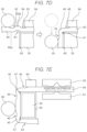
- FIG. 12 A is a schematic cross-sectional view, in the axial direction, of a salient pole to which another coil is attached.
- FIG. 12 B is a schematic cross-sectional view, in the axial direction, of a salient pole to which still another coil is attached.
- FIG. 1 is a schematic diagram of a motor according to a first exemplary embodiment.
- a radial direction of motor 100 or stator 10 may be referred to as a “radial direction”
- an outer circumferential direction may be referred to as a “circumferential direction”
- an extending direction of shaft 71 (the direction perpendicular to the paper surface in FIG. 1 ) may be referred to as an “axial direction”.
- the radial direction is referred to as a first direction in some cases.
- a center side of motor 100 is referred to as an inner side
- an outer peripheral side is referred to as an outer side, in some cases.
- motor 100 includes stator 10 and rotor 70 .
- Motor 100 includes other components than the above components, for example, components such as a bearing that pivotally supports a frame and the shaft; however, illustration and description of those components are omitted for convenience of description.
- Stator 10 includes: an annular yoke 20 ; a plurality of salient poles 30 connected to an inner periphery of yoke 20 and provided at equal intervals along the inner periphery; and coils 40 housed in slots provided between the salient poles 30 adjacent to each other in the circumferential direction.
- Stator 10 is disposed on radially outside the rotor 70 with a predetermined gap between stator 10 and rotor 70 . Slots are the spaces between salient poles 30 adjacent to each other in the circumferential direction.
- Yoke 20 and salient poles 30 are each formed by, for example, stacking electromagnetic steel sheets containing silicon and the like and then by punching the stacked electromagnetic steel sheets.
- the yoke 20 is formed by the following process: a plurality of divided yokes 21 each having salient pole 30 connected to its inner periphery are arranged in one direction and connected to each other; and the connected yokes 21 are bent to form an annular shape, and both ends of the connected yokes 21 are coupled to each other.
- Across-sectional shape of each salient pole 30 in the axial direction is a rectangular shape, in other words, a quadrangular shape (see FIG. 4 ).
- coil 40 is a component formed of n turns of wound conductive wire 50 (see FIG. 3 ), where n is an integer of 2 or more. Coils 40 are housed in the slots, each being attached to one of the plurality of salient poles 30 via insulator 60 (see FIGS. 4 to 6 ).
- a winding wire may be wound around each salient pole 30 to which insulator 60 is attached, for example.
- coils 40 previously wound in accordance with the shape of salient pole 30 may be attached from a radially outer end of respective ones of salient poles 30 . In this case, salient poles 30 to which coils 40 are mounted are connected to divided yokes 21 .
- coils 40 each may be referred to as coil U 1 to coil U 4 , coil V 1 to coil V 4 , and coil W 1 to coil W 4 , in some cases.
- Rotor 70 includes: shaft 71 ; substantially cylindrical rotor core 72 in which shaft 71 is contained at an axial center and in which a plurality of permanent magnets 73 are contained on the outer peripheral side; and the plurality of permanent magnets 73 disposed to face stator 10 in such a manner that N poles and S poles of the permanent magnets 73 are alternately arranged along an outer circumferential direction of rotor core 72 .
- a material, a shape, and a quality of material of permanent magnets 73 can be appropriately changed depending on an output of motor 100 and the like.
- rotor core 72 is also formed by processing stacked electromagnetic steel sheets.
- Coils U 1 to U 4 , V 1 to V 4 , and W 1 to W 4 are each connected in series.
- Three phase currents of U, V, and W having 120° phase differences in electric angle are respectively supplied to coils U 1 to U 4 , V 1 to V 4 , and W 1 to W 4 to excite the coils, thereby generating a rotating magnetic field in stator 10 .
- the rotating magnetic field and the magnetic field generated by permanent magnets 73 provided in rotor 70 causes an interaction between them, and a rotational torque is thus generated in rotor 70 .
- shaft 71 Being supported by a bearing (not shown), shaft 71 rotates about an axial line that passes through a center of shaft 71 and extends in the axial direction.
- FIG. 2 is a perspective view showing coil 40 according to the first exemplary embodiment.
- FIG. 3 is a cross-sectional view taken along line III-III in FIG. 2 .
- FIG. 4 is a schematic cross-sectional view, in the axial direction, of a salient pole to which coil 40 is attached.
- FIG. 5 is an enlarged view of the part surrounded by the two-dot chain line in FIG. 4 .
- FIG. 6 is a cross-sectional view taken along line VI-VI in FIG. 5 .
- FIGS. 4 and 5 each illustrate a cross-section of a k-th turn of coil 40 , where k is an integer and 1 ⁇ k ⁇ n.
- FIG. 6 illustrates only a part of salient pole 30 around which coil 40 is wound.
- coil 40 has conductive wire 50 (see FIG. 3 ) spirally wound therearound.
- Coil 40 is a component configured with conductive wire 50 stacked n turns in a predetermined first direction, in this case, in the radial direction.
- Coil 40 has led-out portions 41 at both ends thereof. Led-out portions 41 are used for connection with another coil 40 or connection with an electric wire (not illustrated) drawn from outside of motor 100 .
- conductive wire 50 of coil 40 is configured with metal wire 51 made of conductive metal and insulating film 52 covering a surface of the metal wire.
- a cross-section of metal wire 51 is substantially rectangular, and corner portions thereof are rounded. This configuration is to suppress concentration of a stress on insulating film 52 at a corner portion of metal wire 51 and to thereby suppress damage to insulating film 52 and suppress lowering of strength of insulating film 52 below a required strength.
- insulating film 52 enamel or the like is used, for example.
- insulation film 52 is not limited to this example, and other insulating resin materials may be used.
- Material of metal wire 51 is preferably a low resistivity material such as copper, a copper-based alloy, aluminum, or an aluminum-based alloy.
- first surface 50 a corresponds to an inner peripheral surface of coil 40
- second surface 50 b corresponds to an outer peripheral surface of coil 40 .
- Coil 40 has an axial direction dimension La of about 15 mm to 100 mm, a circumferential direction dimension Wa of about 4 mm to 90 mm, and a radial direction dimension Ha of about 10 mm to 150 mm.
- Conductive wire 50 has a thickness Tb of about 0.1 mm to 5 mm and a width Wb of about 1 mm to 20 mm.
- the k-th turn of coil 40 has a square annular shape in accordance with the cross-sectional shapes of salient pole 30 and insulator 60 .
- Insulator 60 has, on a part to which coil 40 is attached, a shape that is along the outer peripheral surface of salient pole 30 , in other words, insulator 60 has a rectangular cylindrical shape.
- Insulator 60 is a component made of an insulating resin and electrically insulates coil 40 from salient pole 30 .
- the k-th turn of coil 40 has first straight portion 42 a , second straight portion 42 b , third straight portion 42 c , and fourth straight portion 42 d , and has first corner portion 43 a , second corner portion 43 b , third corner portion 43 c , and fourth corner portion 43 d respectively extending from ends of first straight portion 42 a , second straight portion 42 b , third straight portion 42 c , and fourth straight portion 42 d .
- first straight portion 42 a , second straight portion 42 b , third straight portion 42 c , and fourth straight portion 42 d may be collectively referred to as straight portion 42
- first corner portion 43 a , second corner portion 43 b , third corner portion 43 c , and fourth corner portion 43 d may be collectively referred to as corner portion 43 .
- First straight portion 42 a and third straight portion 42 c are provided to face each other at a predetermined interval in the circumferential direction.
- Second straight portion 42 b and fourth straight portion 42 d are provided to face each other at a predetermined interval in the axial direction.
- the direction in which first straight portion 42 a and third straight portion 42 c face each other is substantially orthogonal to the direction in which second straight portion 42 b and fourth straight portion 42 d face each other.
- the expression “substantially orthogonal” means being orthogonal, taking into account manufacturing tolerances or assembly tolerances of the components constituting motor 100 , and does not mean being strictly orthogonal.
- the expression “substantially the same” or “substantially identical” means the same or identical, taking into account manufacturing tolerances or assembly tolerances of components constituting motor 100 , and does not mean being exactly the same or identical.
- First corner portion 43 a couples first straight portion 42 a and fourth straight portion 42 d to each other.
- Second corner portion 43 b couples first straight portion 42 a and second straight portion 42 b to each other.
- Third corner portion 43 c couples second straight portion 42 b and third straight portion 42 c to each other.
- Fourth corner portion 43 d couples third straight portion 42 c and fourth straight portion 42 d to each other.
- first bent portion 44 , second bent portion 45 , and third bent portion 46 are formed on an outer peripheral surface of each of first corner portion 43 a , second corner portion 43 b , third corner portion 43 c , and fourth corner portion 43 d .
- first bent portion 44 and third bent portion 46 are formed on the outer peripheral surface of first corner portion 43 a .
- First bent portion 44 and third bent portion 46 are bent toward the inner peripheral side.
- First bent portion 44 and third bent portion 46 have a concave shape when viewed on a cross-section in the axial direction.
- Second bent portion 45 is formed on the outer peripheral surface of first corner portion 43 a .
- Second bent portion 45 is bent toward the outer peripheral side.
- Second bent portion 45 has a convex shape when viewed on the cross-section in the axial direction.
- Third bent portion 46 is formed on a side opposite to first bent portion 44 with second bent portion 45 interposed therebetween.
- a curvature C 1 of first bent portion 44 , a curvature C 2 of second bent portion 45 , and a curvature C 3 of third bent portion 46 are different from each other (see FIG. 5 ).
- First bent portion 44 , second bent portion 45 , and third bent portion 46 formed on each of the outer peripheral surfaces of second corner portion 43 b , third corner portion 43 c , and fourth corner portion 43 d also have the same shapes.
- Recessed portion 47 directed to an outer peripheral surface of second bent portion 45 is formed in an inner peripheral surface of second bent portion 45 formed on each of first corner portion 43 a , second corner portion 43 b , third corner portion 43 c , and fourth corner portion 43 d .
- the four corner portions of salient pole 30 are contained, via insulator 60 , in respective ones of recessed portions 47 formed in first corner portion 43 a , second corner portion 43 b , third corner portion 43 c , and fourth corner portion 43 d.
- the k-th turn of coil 40 is configured such that a line width We between second bent portion 45 and recessed portion 47 is 90% or more of the line width Wb of straight portion 42 .
- a thickness T bi on the inner peripheral side and a thickness T bo on the outer peripheral side of the k-th turn are substantially equal to each other.
- the thickness T bi on the inner peripheral side and the thickness T bo on the outer peripheral side of the k-th turn are substantially equal to each other also at second corner portion 43 b , third corner portion 43 c , and fourth corner portion 43 d.
- coil 40 is a so-called edgewise winding coil, and conductive wire 50 is bent on first surfaces 50 a and second surfaces 50 b , which are short sides.
- FIG. 7 A is an explanatory view of a wire rod preparing step in a coil manufacturing process.
- FIG. 7 B is an explanatory view of a recess forming step.
- FIG. 7 C is a schematic cross-sectional view taken along line VIIC-VIIC in FIG. 7 B .
- FIG. 7 D is an explanatory view of a winding step.
- FIG. 7 E is a process explanatory view in a case where a recess forming step and the winding step are successively performed.
- coil wire rod 80 is prepared (wire rod preparing step).
- Coil wire rod 80 is conductive wire 50 before being spirally wound.
- Coil wire rod 80 has a cross-sectional structure illustrated in FIG. 3 , that is, a substantially rectangular cross-section.
- First surface 80 a , second surface 80 b , third surface 80 c , and fourth surface 80 d illustrated in FIGS. 7 A to 7 E respectively correspond to first surface 50 a , second surface 50 b , third surface 50 c , and fourth surface 50 d illustrated in FIG. 3 .
- coil wire rod 80 is set on recess formation first jig 91 such that first surface 80 a , which is one side surface of coil wire rod 80 , faces recess formation first jig 91 .
- Coil wire rod 80 is set such that second surface 80 b of coil wire rod 80 , which faces first surface 80 a , faces recess formation second jig 92 .
- Widths of first surface 80 a and second surface 80 b are substantially equal to the thickness Tb of conductive wire 50 illustrated in FIG. 3 .
- the widths of third surface 80 c and fourth surface 80 d are substantially equal to the width Wb of conductive wire 50 illustrated in FIG. 3 .
- Recess formation first jig 91 and recess formation second jig 92 are positioned relatively to each other so as to sandwich coil wire rod 80 .
- Holding plates 93 are brought into contact with third surface 80 c and fourth surface 80 d of coil wire rod 80 so as to fixedly sandwich coil wire rod 80 .
- recess formation first jig 91 and recess formation second jig 92 respectively come into contact with and press against first surface 80 a and second surface 80 b of coil wire rod 80 .
- recess formation first jig 91 is provided with first protrusion 91 a .
- Recess formation second jig 92 is provided with second protrusion 92 a and third protrusion 92 b .
- first recess 81 that corresponds to a shape of first protrusion 91 a and is directed toward second surface 80 b .
- second recess 82 that corresponds to a shape of second protrusion 92 a and is directed toward first surface 80 a
- third recess 83 that corresponds to a shape of third protrusion 92 b and is directed toward first surface 80 a (recess forming step).
- second recess 82 and third recess 83 are formed on both sides of first recess 81 .
- first recess 81 , second recess 82 , and third recess 83 are simultaneously formed, a part of coil wire rod 80 positioned between second recess 82 and third recess 83 is lifted on a first surface 80 a side, whereby first protrusion 84 is formed.
- first surface 80 a side of coil wire rod 80 is sandwiched by holding plates 93 , coil wire rod 80 is deformed, so that coil wire rod 80 becomes thicker on a second surface 80 b side.
- a part of coil wire rod 80 sandwiched by holding plates 93 , in other words, a part where first recess 81 , second recess 82 , and third recess 83 are formed is made thicker on the second surface 80 b side.
- first recess 81 , second recess 82 , and third recess 83 are formed, holding plates 93 , recess formation first jig 91 , and recess formation second jig 92 are separated from coil wire rod 80 . Then, coil wire rod 80 is fed in a longitudinal direction of coil wire rod 80 by a predetermined distance, and the recess forming step is executed again. By repeating such a process, a plurality of sets of first recesses 81 , second recesses 82 , third recesses 83 , and first protrusions 84 are formed along the longitudinal direction of coil wire rod 80 at predetermined intervals.
- first surface 80 a of coil wire rod 80 is brought into contact with a surface of insulator 60 attached to salient pole 30 , and guide 94 is brought into contact with the vicinity of third recess 83 on second surface 80 b , whereby coil wire rod 80 is sandwiched and fixed.
- salient pole 30 and guide 94 are prevented from being caught on first recess 81 , second recess 82 , third recess 83 , and first protrusion 84 .
- bending jig 95 is brought into contact with the vicinity of second recess 82 on second surface 80 b to press coil wire rod 80 , and coil wire rod 80 is wound around the surface of insulator 60 (winding step).
- first recess 81 is deformed into recessed portion 47 illustrated in FIGS. 2 to 5
- second recess 82 and third recess 83 are respectively deformed into first bent portion 44 and third bent portion 46 illustrated in FIGS. 2 to 5
- the first protrusion 84 is deformed to become second bent portion 45 .
- a part not in contact with the corner portion of insulator 60 becomes above-described straight portion 42 .
- a part of coil wire rod 80 sandwiched by holding plates 93 in the recess forming step in other words, a part where first recess 81 , second recess 82 , and third recess 83 are to be formed is extended on the second surface 80 b side in the winding step.
- the thickness on the first surface 80 a side and the thickness on the second surface 80 b side that is, the thickness T bi on the inner peripheral side and the thickness T bo on the outer peripheral side illustrated in FIG. 6 are substantially equal.
- first bent portion 44 , second bent portion 45 , third bent portion 46 , and recessed portion 47 are formed, guide 94 and bending jig 95 are separated from coil wire rod 80 , coil wire rod 80 is fed in the longitudinal direction of coil wire rod 80 by a predetermined distance, and the winding step is executed again. For example, by repeating this step four times, first corner portion 43 a , second corner portion 43 b , third corner portion 43 c , and fourth corner portion 43 d of the k-th turn of coil 40 are formed. By further repeating a series of the steps, coil 40 having n turns of spirally wound and stacked coil wire rod 80 is finally formed.
- recess formation first jig 91 , recess formation second jig 92 , holding plates 93 , guide 94 , and bending jig 95 may be disposed at predetermined positions along the longitudinal direction of coil wire rod 80 , and coil 40 may be formed by repeatedly executing the recess forming step and the winding step while successively feeding coil wire rod 80 in the longitudinal direction.
- coil 40 is cut apart from coil wire rod 80 .
- a plurality of coils 40 may be divided by a unit of one coil or by a unit of a plurality of coils after the plurality of coils 40 are formed on one coil wire rod 80 .
- coil wire rod 80 is wound around another member having a rectangular cross-section corresponding to the shape of salient pole 30 , and coil wire rod 80 having been wound is removed from the another member after the winding step is completed.
- salient pole 30 salient pole 30 to which insulator 60 is attached, and the above-mentioned another member may be collectively referred to as a “wound member”.
- coil 40 is configured such that conductive wire 50 having a substantially rectangular cross-section is wound spirally and is stacked n turns in the radial direction (first direction).
- the k-th turn of coil 40 has at least straight portion 42 and corner portion 43 extending from the end part of straight portion 42 .
- first bent portion 44 bent toward the inner peripheral side
- second bent portion 45 bent toward the outer peripheral side
- third bent portion 46 bent toward the inner peripheral side on the opposite side of first bent portion 44 with second bent portion 45 between first bent portion 44 and third bent portion 46 .
- the curvature C 1 of first bent portion 44 , the curvature C 2 of second bent portion 45 , and the curvature C 3 of third bent portion 46 are different from each other.
- salient pole 30 of stator 10 around which coil 40 is wound has a rectangular prism shape whose cross-section is rectangular.
- coil 40 When coil 40 is mounted along the outer peripheral surface of salient pole 30 , stress concentrates on conductive wire 50 constituting coil 40 at a part being in contact with the corner portion thereof, and there is a possibility that insulating film 52 gets damaged or that a required strength cannot be secured.
- insulator 60 is attached to salient pole 30 , since insulator 60 has a rectangular cylindrical shape corresponding to the shape of salient pole 30 , there is a possibility that insulation properties of coil 40 are similarly deteriorated at the corner portion.
- first bent portion 44 , second bent portion 45 , and third bent portion 46 are different from each other. Therefore, a degree of stress applied to first bent portion 44 , second bent portion 45 , and third bent portion 46 are different from each other. As a result, the stress can be more effectively dispersed.
- coil 40 is configured by winding conductive wire 50 of a so-called flat square wire having a substantially rectangular cross-section. Therefore, when coil 40 is attached to salient pole 30 of stator 10 , the space factor in the slot is increased.
- At least two of first bent portion 44 , second bent portion 45 , and third bent portion 46 may be made to have different curvatures. Also with this arrangement, the stress is dispersed on first bent portion 44 , second bent portion 45 , and third bent portion 46 , and the damage of conductive wire 50 can be suppressed, so that the decrease in the strength of insulating film 52 and consequently the decrease in the insulation properties of coil 40 can be suppressed.
- Recessed portion 47 directed toward the outer peripheral side is formed on the inner peripheral surface of second bent portion 45 of coil 40 .
- coil 40 when coil 40 is wound around the wound member, the corner portion of the wound member is contained in recessed portion 47 .
- the line width We between second bent portion 45 and recessed portion 47 is preferably 90% or more of the line width Wb of straight portion 42 .
- coil 40 With such a configuration of coil 40 , it is possible to suppress a local increase in resistance of coil 40 . Therefore, it is possible to reduce heat generation when a current flows through coil 40 . As a result, for example, it is possible to suppress loss caused by the current flowing through coil 40 when motor 100 is driven, whereby the efficiency of motor 100 is improved.
- the thickness of the k-th turn in the radial direction is substantially same between the outer peripheral side and the inner peripheral side. That is, as illustrated in FIG. 6 , the thickness T bi on the inner peripheral side and the thickness T bo on the outer peripheral side are substantially equal.
- conductive wire 50 preferably includes spirally wound metal wire 51 and insulating film 52 covering metal wire 51 .
- a manufacturing method for a coil includes at least the following steps: a wire rod preparing step for preparing coil wire rod 80 (conductive wire 50 ) having a first surface 80 a and second surface 80 b opposed to first surface 80 a ; a recess forming step including: forming, in first surface 80 a of coil wire rod 80 , first recesses 81 directed toward second surface 80 b at predetermined intervals along a longitudinal direction of coil wire rod 80 ; and forming, on the second surface 80 b , second recess 82 and third recess 83 that are directed toward first surface 80 a on respective ones of both sides of a position opposed to each of first recesses 81 ; and a winding step of winding coil wire rod 80 around a wound member having a rectangular cross-section, wherein first surface 80 a of coil wire rod 80 is in contact with a surface of the wound member, and corner portions of wound member are each contained in one of first recesses 81 .
- Stator 10 is stator 10 for motor 100 , and includes at least annular yoke 20 , the plurality of salient poles 30 connected to the inner periphery of yoke 20 , and coils 40 attached to respective ones of the plurality of salient poles 30 .
- stator 10 With such a configuration of stator 10 , it is possible to suppress a decrease in insulation between salient poles 30 and coils 40 . In addition, the space factor in the slot and consequently the efficiency of motor 100 is increased.
- Recessed portion 47 is formed, toward the outer peripheral surface, in the inner peripheral surface of second bent portion 45 formed on each of first corner portion 43 a , second corner portion 43 b , third corner portion 43 c , and fourth corner portion 43 d .
- the four corner portions of salient pole 30 are contained in respective ones of recessed portions 47 formed in first corner portion 43 a , second corner portion 43 b , third corner portion 43 c , and fourth corner portion 43 d.
- stator 10 With such a configuration of stator 10 , it is possible to suppress damage to conductive wire 50 of coil 40 . Furthermore, it is possible to suppress a decrease in insulation between salient pole 30 and coil 40 caused by local concentration of stress on insulating film 52 of coil 40 at the corner portions of salient pole 30 . Furthermore, it is possible to wind a winding wire along the outer peripheral surface of salient pole 30 or insulator 60 attached to salient pole 30 . Therefore, coil 40 and consequently motor 100 can be downsized.
- Motor 100 includes at least stator 10 and rotor 70 that is disposed radially inside stator 10 with a predetermined interval therebetween.
- FIGS. 8 A and 8 B are schematic cross-sectional views of a coil wire rod according to a first modification.
- FIG. 8 A illustrates a cross-section of a part corresponding to the straight portion of the coil.
- FIG. 8 B illustrates a cross-section of a part corresponding to the corner portion.
- the same parts as those in the first exemplary embodiment are denoted by the same reference marks, and the detailed description thereof will be omitted.
- FIGS. 8 A and 8 B show cross-sections at the end of the wire rod preparing step shown in the first exemplary embodiment. Therefore, it can also be said that FIG. 8 B illustrates a cross-section of a part where the first to third recesses are to be formed.
- the cross-section of the part corresponding to straight portion 42 of coil 40 is the same as the cross-section illustrated in FIG. 3 .
- the thickness Tc on first surface 80 a side is thinner than the thickness Tb on second surface 80 b side.
- first recess 81 , second recess 82 , and third recess 83 are to be formed is thickened on the second surface 80 b side.
- coil wire rod 80 is not sufficiently deformed in some cases, so that coil wire rod 80 will not be thickened on the second surface 80 b side.
- the inner peripheral side is thinner than the outer peripheral side at corner portion 43 of coil 40 in some cases, so that it will be difficult to sufficiently increase the space factor of coil 40 .
- the second surface 80 b side of such part is stretched in the winding step.
- the thickness on first surface 80 a side and the thickness on second surface 80 b side that is, the thickness T bi on the inner peripheral side and the thickness T bo on the outer peripheral side can be made substantially equal to each other.
- coil wire rod 80 illustrated in FIGS. 8 A and 8 B can be easily obtained by shaping metal wire 51 using a predetermined jig in a step of stretching and shaping metal wire 51 .
- the first surface 80 a side of the part of the conductive wire 50 where first recess 81 , second recess 82 , and third recess 83 are to be formed can be thinned by pressing or cutting.
- FIG. 9 is an explanatory view of a coil manufacturing process according to a second modification.
- the same parts as those in the first exemplary embodiment are denoted by the same reference marks, and the detailed description thereof will be omitted.
- first recess 81 corresponding to recessed portion 47 is formed in coil wire rod 80 , if first recess 81 is formed symmetrically with respect to an axis in the width direction of coil wire rod 80 , in other words, with respect to axis AA substantially orthogonal to the longitudinal direction of coil wire rod 80 and passing through a bottom portion of first recess 81 , coil wire rod 80 is stretched in the vicinity of first recess 81 in the winding step.
- the finally formed recessed portion 47 can have an asymmetric shape. In such a case, it is necessary to give an allowance to a gap between first recess 81 and the wound member including salient pole 30 so that the corner portion of salient pole 30 and recessed portion 47 are not strongly in contact with each other.
- this measure can make the line width Wc between second bent portion 45 and recessed portion 47 narrower at corner portion 43 , so that the resistance of coil 40 can increase.
- first recess 81 is formed so as to be asymmetric with respect to axis AA in the width direction of coil wire rod 80 , so that the gap between first recess 81 and the corner portion of the wound member is reduced at the end of the winding step.
- the present modification can make smaller a size of recessed portion 47 of coil 40 corresponding to first recess 81 . Therefore, it is possible to suppress a local increase in resistance of coil 40 caused by a decrease in the above-described line width Wc at corner portion 43 of coil 40 . As a result, it is possible to suppress the loss caused by the current flowing through coil 40 when motor 100 is driven, and it is thereby possible to increase the efficiency of motor 100 . In addition, the size of recessed portion 47 can be reduced. As a result, coil 40 can be downsized.
- FIG. 10 is a plan view of a coil wire rod according to a third modification. Specifically, FIG. 10 illustrates the coil wire rod at the end of the recess forming step.
- the same parts as those in the first exemplary embodiment are denoted by the same reference marks, and the detailed description thereof will be omitted.
- first recess 81 , second recess 82 , third recess 83 , and first protrusion 84 are formed.
- a distance A between a bottom of second recess 82 and a bottom of third recess 83 and a distance B between the bottom of third recess 83 and a top of first protrusion 84 along a line width direction of coil wire rod 80 correspond to the size of corner portion 43 of coil 40 formed when coil wire rod 80 (conductive wire 50 ) is wound.
- first recess 81 , second recess 82 , third recess 83 , and first protrusion 84 are formed such that both the distances A and B are also approximately doubled.
- the distances A and B may not be changed in direct proportion to the line width of coil wire rod 80 .
- First recess 81 , second recess 82 , third recess 83 , and the first protrusion 84 may be formed such that as the line width of coil wire rod 80 becomes wider, both the distance A and the distance B become accordingly longer.
- FIG. 11 A is a schematic cross-sectional view of a motor according to a second exemplary embodiment.
- FIG. 11 B is a schematic cross-sectional view taken along line XIB-XIB in FIG. 11 A .
- motor 300 includes frame 110 , end plate 120 , bearings 210 , 220 , rotor 130 , stator 190 , and brushes 180 .
- a radial direction of motor 300 is referred to as a “radial direction”
- an outer circumferential direction is referred to as a “circumferential direction”
- a direction in which shaft 140 extends is referred to as an “axial direction”.
- the center side of motor 300 is referred to as radially inside, and the outer peripheral side is referred to as radially outside.
- Frame 110 is a bottomed semi-cylindrical metal member having an opening in an upper part.
- End plate 120 is a plate-shaped member made of a molded resin material.
- End plate 120 includes: a substantially disk-shaped base portion 121 ; through hole 122 provided at a center of base portion 121 ; brush holder 123 formed on an inner surface of base portion 121 ; and bearing holder 124 formed on an outer surface of base portion 121 .
- End plate 120 is disposed on frame 110 to cover the opening.
- Rotor 130 is contained in a space defined by frame 110 and end plate 120 .
- Shaft 140 is disposed through through hole 122 of end plate 120 and protrudes from end plate 120 to the outside of frame 110 , and shaft 140 is rotatably supported by bearings 210 , 220 .
- Rotor 130 includes shaft 140 , armature 150 , commutator 160 , and insulator 170 .
- Armature 150 includes armature core 151 , a plurality of salient poles 152 , and armature windings (coils) 153 .
- Shaft 140 is press-fitted in a through hole (not shown) provided at an axial center of armature core 151 , whereby armature 150 is fixedly attached to an outer peripheral surface of shaft 140 .
- armature core 151 On armature core 151 , the plurality of salient poles 152 protruding radially outward are disposed at predetermined intervals in the circumferential direction.
- Armature windings 153 are attached to respective ones of the plurality of salient poles 152 via an insulator 170 made of an insulating resin. Armature windings 153 drawn from armature core 151 are connected (not shown) to commutator 160 .
- Armature core 151 and salient poles 152 are formed by punching a plurality of stacked electromagnetic steel sheets. Armature core 151 and salient poles 152 constitute magnetic paths through which magnetic flux generated in armature windings 153 passes.
- Shaft 140 is provided at an axial center of rotor 130 . Passing through the centers of armature core 151 and commutator 160 , shaft 140 is connected thereto.
- Insulator 170 attached to the salient pole 152 also has a rectangular cylindrical shape corresponding to an outer shape of salient pole 152 .
- Armature winding 153 attached to each of salient poles 152 has the same shape as coil 40 illustrated in FIGS. 2 to 6 . That is, armature winding 153 is coil 40 configured such that conductive wire 50 having a substantially rectangular cross-section is wound spirally and is stacked n turns in the radial direction (first direction). The k-th turn of coil 40 has at least straight portion 42 and corner portion 43 extending from the end part of straight portion 42 .
- first bent portion 44 bent toward the inner peripheral side
- second bent portion 45 bent toward the outer peripheral side
- third bent portion 46 bent toward the inner peripheral side and located on the opposite side of first bent portion 44 with second bent portion 45 between first bent portion 44 and third bent portion 46 .
- At least two of first bent portion 44 , second bent portion 45 , and third bent portion 46 have different curvatures from each other.
- recessed portion 47 directed toward the outer peripheral surface is formed in the inner peripheral surface of second bent portion 45 formed on each of first corner portion 43 a , second corner portion 43 b , third corner portion 43 c , and fourth corner portion 43 d .
- the four corner portions of salient pole 152 are contained in respective ones of recessed portions 47 formed in first corner portion 43 a , second corner portion 43 b , third corner portion 43 c , and fourth corner portion 43 d.
- Commutator 160 is fixedly attached to the outer peripheral surface of shaft 140 along the axial direction at a predetermined interval from armature 150 .
- Stator 190 includes frame 110 and a plurality of permanent magnets 191 disposed on an inner peripheral surface of frame 110 in the circumferential direction at predetermined intervals. Permanent magnets 191 adjacent to each other in the circumferential direction are disposed to have different polarities. Frame 110 also functions as a yoke constituting a magnetic circuit with permanent magnets 191 .
- Brushes 180 are made of a carbon brush material such as graphite containing a solid lubricant. Brushes 180 are held in brush holder 123 provided on an inner surface of end plate 120 . Brushes 180 are pressed against commutator 160 by brush springs (not shown).
- Electric power is supplied to motor 300 from outside through electric wires (not shown) drawn out from an electric wire drawing port (not shown) provided in end plate 120 .
- an armature current flows through armature windings 153 via brushes 180 and commutator 160 .
- An interaction occurs between a magnetic field generated by permanent magnets 191 of stator 190 and a magnetic field generated by the armature current flowing through armature windings 153 , whereby a rotational torque is generated in rotor 130 .
- Shaft 140 is supported by bearings 210 , 220 , and rotor 130 rotates about an axial line that passes through an axial center of shaft 140 and extends in the axial direction.
- brushes 180 and commutator 160 cyclically repeat contact and separation, and directions of the armature currents flowing through armature windings 153 are changed in accordance with this cycle.
- shaft 140 can continuously rotate in the clockwise direction or the counterclockwise direction.
- rotor 130 is rotor 130 of motor 300 , and includes: at least shaft 140 rotatably provided about a predetermined axial line; the plurality of salient poles 152 provided on an outer peripheral side of shaft 140 and extending in the radial direction of motor 300 ; and armature windings (coils) 153 attached to respective ones of the plurality of salient poles 152 .
- Motor 300 includes at least: rotor 130 ; and stator 190 disposed radially outside rotor 130 with a predetermined interval from rotor 130 .
- first recess 81 described in the second modification may be formed on coil wire rod 80 (conductive wire 50 ), and then, coil wire rod 80 (conductive wire 50 ) may be spirally wound to form armature winding (coil) 153 described in the second exemplary embodiment.
- coil 40 may have a configuration other than the configuration in which metal wire 51 having insulating film 52 formed on the surface thereof is wound as described in the first exemplary embodiment.
- coil 40 may be constituted by conductive wire 50 on which insulating film 52 is formed after metal wire 51 is wound.
- coil 40 may be constituted by a conductive wire on which insulating film 52 is formed while metal wire 51 is being wound.
- insulating film 52 may be omitted, and metal wire 51 may be used as conductive wire 50 .
- coil 40 is configured by winding metal wire 51 .
- coil 153 described in the second exemplary embodiment may be configured with conductive wire 50 made in such a manner that insulating film 52 is formed after or while metal wire 51 is wound.
- insulating film 52 may be omitted, and metal wire 51 may be used as conductive wire 50 .
- insulating paper may be used instead of insulator 60 or insulator 170 .
- the distance between each corner portion of salient pole 30 or salient pole 152 and coil 40 or coil 153 is shorter.
- the stress applied by the corner portion to coil 40 or coil 153 is larger. Therefore, when coil 40 or coil 153 of the present disclosure is applied to stator 190 or rotor 130 , it is possible to suppress damage to conductive wire 50 constituting coil 40 or coil 153 .
- a capacity of the slot provided in at least one of stator 190 and rotor 130 can be increased as compared with the case of using the rectangular tube-shaped insulator 60 or insulator 170 . Therefore, the space factor of coil 40 or coil 153 and consequently the efficiency of motor 100 or 300 can be increased.
- FIG. 12 A is a schematic cross-sectional view, in the axial direction, of a salient pole to which another type of coil is attached.
- FIG. 12 B is a schematic cross-sectional view, in the axial direction, of a salient pole to which still another type of coil is attached.
- first bent portion 44 , second bent portion 45 , and third bent portion 46 are provided at each corner portion 43 of coil 40 .
- third bent portion 46 may be omitted.
- first bent portion 44 may be omitted.
- first bent portion 44 or third bent portion 46 bent toward the inner peripheral side there are formed at least: first bent portion 44 or third bent portion 46 bent toward the inner peripheral side; and second bent portion 45 bent toward the outer peripheral side.
- the curvature C 1 of first bent portion 44 needs to be different from the curvature C 2 of second bent portion 45
- the curvature C 3 of third bent portion 46 needs to be different from the curvature C 2 of second bent portion 45 .
- the stress can be dispersed at each bent portion on the outer peripheral side of corner portion 43 , so that the same effect as that of the first exemplary embodiment can be obtained.
- coil 153 described in the second exemplary embodiment is configured in the same manner as the configuration illustrated FIG. 12 A or 12 B , the same effect is provided.
- each of first bent portion 44 , second bent portion 45 , and third bent portion 46 does not need to have a uniform curvature.
- a plurality of portions having different curvatures may be formed in first bent portion 44 .
- the motor to which coil 40 or coil 153 of the present disclosure can be applied is not limited to motor 100 or motor 300 described in the first exemplary embodiment or the second exemplary embodiment.
- the coil of the present disclosure may be applied to an outer-rotor type brushless motor.
- a plurality of salient poles are provided on a stator disposed at the axial center of the motor, and the coils of the present disclosure are attached to respective ones of the plurality of salient poles.
- the coil of the present disclosure increases its space factor in the stator or the rotor, and at the same time, secures its insulation. Therefore, the coil is useful, for example, for application to a motor used in an in-vehicle application or an industrial application.
Landscapes
- Engineering & Computer Science (AREA)
- Power Engineering (AREA)
- Manufacturing & Machinery (AREA)
- Manufacture Of Motors, Generators (AREA)
- Windings For Motors And Generators (AREA)
- Insulation, Fastening Of Motor, Generator Windings (AREA)
Applications Claiming Priority (3)
| Application Number | Priority Date | Filing Date | Title |
|---|---|---|---|
| JP2019111731 | 2019-06-17 | ||
| JP2019-111731 | 2019-06-17 | ||
| PCT/JP2020/020070 WO2020255614A1 (ja) | 2019-06-17 | 2020-05-21 | コイル及びそれを備えたステータ、ロータ、モータ並びにコイルの製造方法 |
Publications (2)
| Publication Number | Publication Date |
|---|---|
| US20220320932A1 US20220320932A1 (en) | 2022-10-06 |
| US12021424B2 true US12021424B2 (en) | 2024-06-25 |
Family
ID=74037086
Family Applications (1)
| Application Number | Title | Priority Date | Filing Date |
|---|---|---|---|
| US17/607,923 Active 2041-05-10 US12021424B2 (en) | 2019-06-17 | 2020-05-21 | Coil, and stator, rotor, and motor equipped with same, and manufacturing method for coil |
Country Status (5)
| Country | Link |
|---|---|
| US (1) | US12021424B2 (https=) |
| EP (1) | EP3985840A4 (https=) |
| JP (1) | JP7442050B2 (https=) |
| CN (1) | CN113939979B (https=) |
| WO (1) | WO2020255614A1 (https=) |
Families Citing this family (6)
| Publication number | Priority date | Publication date | Assignee | Title |
|---|---|---|---|---|
| US11811282B2 (en) * | 2018-10-18 | 2023-11-07 | Panasonic Intellectual Property Management Co., Ltd. | Coil device having a core with plate shaped coil bodies |
| KR20220028784A (ko) * | 2020-08-31 | 2022-03-08 | 현대모비스 주식회사 | 코일 어셈블리 및 이를 구비한 모터 |
| JP7841375B2 (ja) * | 2022-07-14 | 2026-04-07 | 株式会社デンソー | 回転電機の製造方法 |
| JP2024082752A (ja) * | 2022-12-09 | 2024-06-20 | ミネベアミツミ株式会社 | モータ用コイル、ステータ及びモータ |
| JP2024084384A (ja) * | 2022-12-13 | 2024-06-25 | ミネベアミツミ株式会社 | モータ用コイル及びモータ |
| WO2024122647A1 (ja) * | 2022-12-09 | 2024-06-13 | ミネベアミツミ株式会社 | モータ用コイル、ステータ及びモータ |
Citations (6)
| Publication number | Priority date | Publication date | Assignee | Title |
|---|---|---|---|---|
| JP2004080860A (ja) | 2002-08-12 | 2004-03-11 | Sumitomo Electric Ind Ltd | モーター部品とその製造方法 |
| US20110048092A1 (en) * | 2009-04-24 | 2011-03-03 | Toyota Jidosha Kabushiki Kaisha | Apparatus for producing motor coil |
| US8122593B2 (en) * | 2008-03-05 | 2012-02-28 | Denso Corporation | Weaving machine for coil assembly of rotary electric machine |
| JP5246020B2 (ja) | 2009-05-07 | 2013-07-24 | 住友電気工業株式会社 | コイル、コイルの製造方法、コイル成形体、及びリアクトル |
| JP2015228476A (ja) * | 2014-06-03 | 2015-12-17 | 株式会社デンソー | コイル装置およびコイル装置の製造方法 |
| US9287743B2 (en) * | 2009-06-29 | 2016-03-15 | Toyota Jidosha Kabushiki Kaisha | Multilayered wound coil, stator, and manufacturing method therefor |
Family Cites Families (16)
| Publication number | Priority date | Publication date | Assignee | Title |
|---|---|---|---|---|
| JPS5246020B2 (https=) | 1972-02-29 | 1977-11-21 | ||
| JPS56124220A (en) * | 1980-03-05 | 1981-09-29 | Hitachi Ltd | Manufacture of flat-braided winding for electric machine |
| JP3673330B2 (ja) * | 1996-07-24 | 2005-07-20 | 本田技研工業株式会社 | 電動機用ステータの製造方法 |
| JP2002222724A (ja) * | 2001-01-25 | 2002-08-09 | San-Ei Electronic Industries Co Ltd | コイルの製造方法 |
| JP2008160946A (ja) * | 2006-12-21 | 2008-07-10 | Toyota Motor Corp | コイル製造方法、及びモータの固定子 |
| JP2008178199A (ja) * | 2007-01-17 | 2008-07-31 | Toyota Motor Corp | コイル製造方法、モータのコイル、及びモータの固定子 |
| JP4626623B2 (ja) * | 2007-03-12 | 2011-02-09 | トヨタ自動車株式会社 | 平角材のエッジワイズ曲げ加工方法、及び加工装置 |
| JP4831125B2 (ja) * | 2008-05-21 | 2011-12-07 | トヨタ自動車株式会社 | 巻線方法、巻線装置、及び固定子 |
| JP5989401B2 (ja) * | 2012-05-23 | 2016-09-07 | トヨタ自動車株式会社 | エッジワイズコイル巻線方法及び巻線装置 |
| JP5939088B2 (ja) * | 2012-08-30 | 2016-06-22 | 株式会社デンソー | 回転電機 |
| CN104737422B (zh) * | 2012-10-16 | 2017-05-24 | 三菱电机株式会社 | 旋转电机的电枢 |
| CN104412494B (zh) * | 2012-10-31 | 2017-03-08 | 三菱电机株式会社 | 旋转电机的线圈以及旋转电机 |
| JP5729368B2 (ja) * | 2012-10-31 | 2015-06-03 | トヨタ自動車株式会社 | セグメントコイルの製造方法 |
| JP5737273B2 (ja) * | 2012-11-15 | 2015-06-17 | 株式会社デンソー | 固定子巻線、および、固定子巻線の製造方法 |
| JP2016076316A (ja) * | 2014-10-02 | 2016-05-12 | トヨタ自動車株式会社 | 絶縁平角導線 |
| JP2018098407A (ja) * | 2016-12-15 | 2018-06-21 | 東芝産業機器システム株式会社 | 巻線及びその製造装置、並びに巻線の製造方法 |
-
2020
- 2020-05-21 WO PCT/JP2020/020070 patent/WO2020255614A1/ja not_active Ceased
- 2020-05-21 US US17/607,923 patent/US12021424B2/en active Active
- 2020-05-21 EP EP20825862.4A patent/EP3985840A4/en active Pending
- 2020-05-21 JP JP2021527487A patent/JP7442050B2/ja active Active
- 2020-05-21 CN CN202080042393.6A patent/CN113939979B/zh active Active
Patent Citations (6)
| Publication number | Priority date | Publication date | Assignee | Title |
|---|---|---|---|---|
| JP2004080860A (ja) | 2002-08-12 | 2004-03-11 | Sumitomo Electric Ind Ltd | モーター部品とその製造方法 |
| US8122593B2 (en) * | 2008-03-05 | 2012-02-28 | Denso Corporation | Weaving machine for coil assembly of rotary electric machine |
| US20110048092A1 (en) * | 2009-04-24 | 2011-03-03 | Toyota Jidosha Kabushiki Kaisha | Apparatus for producing motor coil |
| JP5246020B2 (ja) | 2009-05-07 | 2013-07-24 | 住友電気工業株式会社 | コイル、コイルの製造方法、コイル成形体、及びリアクトル |
| US9287743B2 (en) * | 2009-06-29 | 2016-03-15 | Toyota Jidosha Kabushiki Kaisha | Multilayered wound coil, stator, and manufacturing method therefor |
| JP2015228476A (ja) * | 2014-06-03 | 2015-12-17 | 株式会社デンソー | コイル装置およびコイル装置の製造方法 |
Non-Patent Citations (2)
| Title |
|---|
| International Search Report of PCT application No. PCT/JP2020/020070 dated Aug. 25, 2020. |
| JP-2015228476-A machine translation Dec. 16, 2023. * |
Also Published As
| Publication number | Publication date |
|---|---|
| CN113939979A (zh) | 2022-01-14 |
| JPWO2020255614A1 (https=) | 2020-12-24 |
| EP3985840A4 (en) | 2022-08-10 |
| US20220320932A1 (en) | 2022-10-06 |
| WO2020255614A1 (ja) | 2020-12-24 |
| EP3985840A1 (en) | 2022-04-20 |
| CN113939979B (zh) | 2023-11-07 |
| JP7442050B2 (ja) | 2024-03-04 |
Similar Documents
| Publication | Publication Date | Title |
|---|---|---|
| US12021424B2 (en) | Coil, and stator, rotor, and motor equipped with same, and manufacturing method for coil | |
| US6984909B2 (en) | Motor | |
| CN110492630B (zh) | 旋转电机 | |
| US8941280B2 (en) | DC motor with concentrated windings having connecting wires run through armature slots | |
| US12046972B2 (en) | Motor and stator bus bar | |
| US20190372408A1 (en) | Rotating electric machine | |
| JPWO2020255614A5 (https=) | ||
| BG60932B1 (bg) | Електрически двигател за постоянен ток | |
| US11545880B2 (en) | Segmented stator laminations | |
| US8604659B2 (en) | Stator with insulation for an electric motor, insulation for a stator, and electric power tool | |
| CN113544944A (zh) | 发电电动机及其制造方法 | |
| US20150162786A1 (en) | Transverse flux stator geometry | |
| CN112640274A (zh) | 轴向磁通电机 | |
| CN111316539A (zh) | 绝缘体、包括该绝缘体的定子以及包括该绝缘体的电动机 | |
| US20220311299A1 (en) | Stator and motor | |
| CN108028558B (zh) | 旋转电机以及旋转电机的制造方法 | |
| JP3574581B2 (ja) | 小型モータ | |
| KR102761028B1 (ko) | 축 방향 자속 전기 기계 | |
| US12308718B2 (en) | Molded coil, stator, and rotary electric machine | |
| WO2024000243A9 (zh) | 分段式定子芯、电机和用于制造电机的定子组件的方法 | |
| WO2022264494A1 (ja) | 回転電機および回転電機の製造方法 | |
| JP2009296745A (ja) | 多極アキシャルギャップ型コンデンサ電動機とその製造方法 | |
| JP4548381B2 (ja) | インシュレータ、回転電機およびその製造方法ならびに電動車両 | |
| JPH11285187A (ja) | 永久磁石同期電動機の磁石固定方法 | |
| JP4607823B2 (ja) | 交流回転電機 |
Legal Events
| Date | Code | Title | Description |
|---|---|---|---|
| AS | Assignment |
Owner name: PANASONIC INTELLECTUAL PROPERTY MANAGEMENT CO., LTD., JAPAN Free format text: ASSIGNMENT OF ASSIGNORS INTEREST;ASSIGNORS:SAKAGUCHI, HIROKI;NAKAMURA, YOSHIHARU;KOYAMA, SHOICHI;AND OTHERS;SIGNING DATES FROM 20210930 TO 20211012;REEL/FRAME:059465/0607 |
|
| STPP | Information on status: patent application and granting procedure in general |
Free format text: DOCKETED NEW CASE - READY FOR EXAMINATION |
|
| STPP | Information on status: patent application and granting procedure in general |
Free format text: NON FINAL ACTION MAILED |
|
| STPP | Information on status: patent application and granting procedure in general |
Free format text: RESPONSE TO NON-FINAL OFFICE ACTION ENTERED AND FORWARDED TO EXAMINER |
|
| STPP | Information on status: patent application and granting procedure in general |
Free format text: NOTICE OF ALLOWANCE MAILED -- APPLICATION RECEIVED IN OFFICE OF PUBLICATIONS |
|
| STPP | Information on status: patent application and granting procedure in general |
Free format text: PUBLICATIONS -- ISSUE FEE PAYMENT RECEIVED |
|
| STPP | Information on status: patent application and granting procedure in general |
Free format text: PUBLICATIONS -- ISSUE FEE PAYMENT VERIFIED |
|
| STCF | Information on status: patent grant |
Free format text: PATENTED CASE |