US12018386B2 - Magnetic material including α″-Fe16(NxZ1-x)2 or a mixture of α″-Fe16Z2 and α″-Fe16N2, where Z includes at least one of C, B, or O - Google Patents
Magnetic material including α″-Fe16(NxZ1-x)2 or a mixture of α″-Fe16Z2 and α″-Fe16N2, where Z includes at least one of C, B, or O Download PDFInfo
- Publication number
- US12018386B2 US12018386B2 US16/949,038 US202016949038A US12018386B2 US 12018386 B2 US12018386 B2 US 12018386B2 US 202016949038 A US202016949038 A US 202016949038A US 12018386 B2 US12018386 B2 US 12018386B2
- Authority
- US
- United States
- Prior art keywords
- iron
- carbon
- nitrogen
- ribbons
- soft magnetic
- Prior art date
- Legal status (The legal status is an assumption and is not a legal conclusion. Google has not performed a legal analysis and makes no representation as to the accuracy of the status listed.)
- Active, expires
Links
- 239000000696 magnetic material Substances 0.000 title claims abstract description 117
- 229910000920 Fe16N2 Inorganic materials 0.000 title claims abstract description 73
- 229910052796 boron Inorganic materials 0.000 title claims abstract description 43
- 239000000203 mixture Substances 0.000 title claims description 149
- 238000000034 method Methods 0.000 claims abstract description 169
- 238000002074 melt spinning Methods 0.000 claims abstract description 54
- XEEYBQQBJWHFJM-UHFFFAOYSA-N Iron Chemical compound [Fe] XEEYBQQBJWHFJM-UHFFFAOYSA-N 0.000 claims description 615
- IJGRMHOSHXDMSA-UHFFFAOYSA-N Atomic nitrogen Chemical compound N#N IJGRMHOSHXDMSA-UHFFFAOYSA-N 0.000 claims description 188
- QMQXDJATSGGYDR-UHFFFAOYSA-N methylidyneiron Chemical compound [C].[Fe] QMQXDJATSGGYDR-UHFFFAOYSA-N 0.000 claims description 187
- OKTJSMMVPCPJKN-UHFFFAOYSA-N Carbon Chemical compound [C] OKTJSMMVPCPJKN-UHFFFAOYSA-N 0.000 claims description 162
- 229910052742 iron Inorganic materials 0.000 claims description 159
- 229910052799 carbon Inorganic materials 0.000 claims description 158
- 229910052757 nitrogen Inorganic materials 0.000 claims description 111
- 239000000843 powder Substances 0.000 claims description 102
- SEQUALWBCFCDGP-UHFFFAOYSA-N [C].[N].[Fe] Chemical compound [C].[N].[Fe] SEQUALWBCFCDGP-UHFFFAOYSA-N 0.000 claims description 101
- 238000005121 nitriding Methods 0.000 claims description 98
- QGZKDVFQNNGYKY-UHFFFAOYSA-N Ammonia Chemical compound N QGZKDVFQNNGYKY-UHFFFAOYSA-N 0.000 claims description 71
- 239000000463 material Substances 0.000 claims description 64
- YYXHRUSBEPGBCD-UHFFFAOYSA-N azanylidyneiron Chemical compound [N].[Fe] YYXHRUSBEPGBCD-UHFFFAOYSA-N 0.000 claims description 53
- 238000002844 melting Methods 0.000 claims description 41
- 230000008018 melting Effects 0.000 claims description 41
- 238000005255 carburizing Methods 0.000 claims description 40
- XSQUKJJJFZCRTK-UHFFFAOYSA-N Urea Chemical compound NC(N)=O XSQUKJJJFZCRTK-UHFFFAOYSA-N 0.000 claims description 37
- 238000000137 annealing Methods 0.000 claims description 30
- 229910021529 ammonia Inorganic materials 0.000 claims description 29
- 239000007788 liquid Substances 0.000 claims description 23
- 230000001590 oxidative effect Effects 0.000 claims description 21
- OAKJQQAXSVQMHS-UHFFFAOYSA-N Hydrazine Chemical compound NN OAKJQQAXSVQMHS-UHFFFAOYSA-N 0.000 claims description 20
- 239000004202 carbamide Substances 0.000 claims description 19
- 239000011148 porous material Substances 0.000 claims description 17
- 229910001018 Cast iron Inorganic materials 0.000 claims description 16
- 239000002243 precursor Substances 0.000 claims description 16
- 150000001408 amides Chemical class 0.000 claims description 15
- 238000000498 ball milling Methods 0.000 claims description 15
- PAWQVTBBRAZDMG-UHFFFAOYSA-N 2-(3-bromo-2-fluorophenyl)acetic acid Chemical compound OC(=O)CC1=CC=CC(Br)=C1F PAWQVTBBRAZDMG-UHFFFAOYSA-N 0.000 claims description 9
- 239000002019 doping agent Substances 0.000 claims description 7
- 238000002386 leaching Methods 0.000 claims description 7
- QJGQUHMNIGDVPM-UHFFFAOYSA-N nitrogen group Chemical group [N] QJGQUHMNIGDVPM-UHFFFAOYSA-N 0.000 claims description 4
- 229910052710 silicon Inorganic materials 0.000 claims description 3
- 229910052782 aluminium Inorganic materials 0.000 claims description 2
- 229910052804 chromium Inorganic materials 0.000 claims description 2
- 229910052802 copper Inorganic materials 0.000 claims description 2
- 229910052733 gallium Inorganic materials 0.000 claims description 2
- 229910052732 germanium Inorganic materials 0.000 claims description 2
- 229910052748 manganese Inorganic materials 0.000 claims description 2
- 229910052719 titanium Inorganic materials 0.000 claims description 2
- 229910052720 vanadium Inorganic materials 0.000 claims description 2
- 229910052725 zinc Inorganic materials 0.000 claims description 2
- 229910052726 zirconium Inorganic materials 0.000 claims description 2
- 229910052758 niobium Inorganic materials 0.000 claims 1
- 230000005415 magnetization Effects 0.000 description 55
- 238000002441 X-ray diffraction Methods 0.000 description 41
- 239000000523 sample Substances 0.000 description 38
- 238000010586 diagram Methods 0.000 description 28
- 125000004429 atom Chemical group 0.000 description 22
- 238000002360 preparation method Methods 0.000 description 22
- 230000003647 oxidation Effects 0.000 description 20
- 238000007254 oxidation reaction Methods 0.000 description 20
- 238000003801 milling Methods 0.000 description 19
- 230000009467 reduction Effects 0.000 description 19
- 235000013877 carbamide Nutrition 0.000 description 17
- 229910001337 iron nitride Inorganic materials 0.000 description 17
- VNWKTOKETHGBQD-UHFFFAOYSA-N methane Chemical compound C VNWKTOKETHGBQD-UHFFFAOYSA-N 0.000 description 16
- 230000008569 process Effects 0.000 description 16
- 238000010791 quenching Methods 0.000 description 16
- 230000000171 quenching effect Effects 0.000 description 16
- 238000006722 reduction reaction Methods 0.000 description 16
- CURLTUGMZLYLDI-UHFFFAOYSA-N Carbon dioxide Chemical compound O=C=O CURLTUGMZLYLDI-UHFFFAOYSA-N 0.000 description 14
- 125000004433 nitrogen atom Chemical group N* 0.000 description 14
- 238000004626 scanning electron microscopy Methods 0.000 description 14
- 238000004611 spectroscopical analysis Methods 0.000 description 14
- XLYOFNOQVPJJNP-UHFFFAOYSA-N water Substances O XLYOFNOQVPJJNP-UHFFFAOYSA-N 0.000 description 13
- 229910021398 atomic carbon Inorganic materials 0.000 description 12
- 239000012768 molten material Substances 0.000 description 12
- 239000000155 melt Substances 0.000 description 9
- UGFAIRIUMAVXCW-UHFFFAOYSA-N Carbon monoxide Chemical compound [O+]#[C-] UGFAIRIUMAVXCW-UHFFFAOYSA-N 0.000 description 8
- 229910002092 carbon dioxide Inorganic materials 0.000 description 8
- 239000001569 carbon dioxide Substances 0.000 description 8
- 229910002091 carbon monoxide Inorganic materials 0.000 description 8
- 229910052760 oxygen Inorganic materials 0.000 description 8
- 229910001566 austenite Inorganic materials 0.000 description 7
- 125000004432 carbon atom Chemical group C* 0.000 description 7
- 239000013078 crystal Substances 0.000 description 7
- 239000011888 foil Substances 0.000 description 7
- QVGXLLKOCUKJST-UHFFFAOYSA-N atomic oxygen Chemical compound [O] QVGXLLKOCUKJST-UHFFFAOYSA-N 0.000 description 6
- 238000001816 cooling Methods 0.000 description 6
- 230000001747 exhibiting effect Effects 0.000 description 6
- 229910002804 graphite Inorganic materials 0.000 description 6
- 239000010439 graphite Substances 0.000 description 6
- 229910000734 martensite Inorganic materials 0.000 description 6
- 239000001301 oxygen Substances 0.000 description 6
- 239000002245 particle Substances 0.000 description 6
- UFHFLCQGNIYNRP-UHFFFAOYSA-N Hydrogen Chemical compound [H][H] UFHFLCQGNIYNRP-UHFFFAOYSA-N 0.000 description 5
- 230000015572 biosynthetic process Effects 0.000 description 5
- 229910001873 dinitrogen Inorganic materials 0.000 description 5
- 229910017389 Fe3N Inorganic materials 0.000 description 4
- CKUAXEQHGKSLHN-UHFFFAOYSA-N [C].[N] Chemical compound [C].[N] CKUAXEQHGKSLHN-UHFFFAOYSA-N 0.000 description 4
- 229910045601 alloy Inorganic materials 0.000 description 4
- 239000000956 alloy Substances 0.000 description 4
- 239000003575 carbonaceous material Substances 0.000 description 4
- 229910001567 cementite Inorganic materials 0.000 description 4
- 238000009826 distribution Methods 0.000 description 4
- UQSXHKLRYXJYBZ-UHFFFAOYSA-N iron oxide Inorganic materials [Fe]=O UQSXHKLRYXJYBZ-UHFFFAOYSA-N 0.000 description 4
- 229910000831 Steel Inorganic materials 0.000 description 3
- 238000013019 agitation Methods 0.000 description 3
- 239000012267 brine Substances 0.000 description 3
- 238000000576 coating method Methods 0.000 description 3
- 239000002826 coolant Substances 0.000 description 3
- 239000001307 helium Substances 0.000 description 3
- 229910052734 helium Inorganic materials 0.000 description 3
- SWQJXJOGLNCZEY-UHFFFAOYSA-N helium atom Chemical compound [He] SWQJXJOGLNCZEY-UHFFFAOYSA-N 0.000 description 3
- 239000005457 ice water Substances 0.000 description 3
- 235000013980 iron oxide Nutrition 0.000 description 3
- -1 iron-carbon ribbons) Chemical compound 0.000 description 3
- 239000003921 oil Substances 0.000 description 3
- 239000008188 pellet Substances 0.000 description 3
- 230000035699 permeability Effects 0.000 description 3
- HPALAKNZSZLMCH-UHFFFAOYSA-M sodium;chloride;hydrate Chemical compound O.[Na+].[Cl-] HPALAKNZSZLMCH-UHFFFAOYSA-M 0.000 description 3
- 239000010935 stainless steel Substances 0.000 description 3
- 229910001220 stainless steel Inorganic materials 0.000 description 3
- 239000010959 steel Substances 0.000 description 3
- 239000000126 substance Substances 0.000 description 3
- DLFVBJFMPXGRIB-UHFFFAOYSA-N Acetamide Chemical compound CC(N)=O DLFVBJFMPXGRIB-UHFFFAOYSA-N 0.000 description 2
- XKRFYHLGVUSROY-UHFFFAOYSA-N Argon Chemical compound [Ar] XKRFYHLGVUSROY-UHFFFAOYSA-N 0.000 description 2
- KXDAEFPNCMNJSK-UHFFFAOYSA-N Benzamide Chemical compound NC(=O)C1=CC=CC=C1 KXDAEFPNCMNJSK-UHFFFAOYSA-N 0.000 description 2
- ZOXJGFHDIHLPTG-UHFFFAOYSA-N Boron Chemical compound [B] ZOXJGFHDIHLPTG-UHFFFAOYSA-N 0.000 description 2
- 230000008901 benefit Effects 0.000 description 2
- 239000011248 coating agent Substances 0.000 description 2
- 239000000470 constituent Substances 0.000 description 2
- 238000009792 diffusion process Methods 0.000 description 2
- 239000007789 gas Substances 0.000 description 2
- 238000010438 heat treatment Methods 0.000 description 2
- 239000012535 impurity Substances 0.000 description 2
- 150000002500 ions Chemical class 0.000 description 2
- VBMVTYDPPZVILR-UHFFFAOYSA-N iron(2+);oxygen(2-) Chemical class [O-2].[Fe+2] VBMVTYDPPZVILR-UHFFFAOYSA-N 0.000 description 2
- 230000004044 response Effects 0.000 description 2
- 239000007787 solid Substances 0.000 description 2
- 239000006104 solid solution Substances 0.000 description 2
- 230000009466 transformation Effects 0.000 description 2
- 229910017112 Fe—C Inorganic materials 0.000 description 1
- ZHNUHDYFZUAESO-UHFFFAOYSA-N Formamide Chemical compound NC=O ZHNUHDYFZUAESO-UHFFFAOYSA-N 0.000 description 1
- 229910002651 NO3 Inorganic materials 0.000 description 1
- 239000000853 adhesive Substances 0.000 description 1
- 230000001070 adhesive effect Effects 0.000 description 1
- 239000003570 air Substances 0.000 description 1
- 239000012080 ambient air Substances 0.000 description 1
- 125000003277 amino group Chemical group 0.000 description 1
- 229910052786 argon Inorganic materials 0.000 description 1
- 239000007833 carbon precursor Substances 0.000 description 1
- 150000001732 carboxylic acid derivatives Chemical class 0.000 description 1
- 150000001735 carboxylic acids Chemical class 0.000 description 1
- 238000006243 chemical reaction Methods 0.000 description 1
- 238000005056 compaction Methods 0.000 description 1
- 239000001257 hydrogen Substances 0.000 description 1
- 229910052739 hydrogen Inorganic materials 0.000 description 1
- 125000002887 hydroxy group Chemical group [H]O* 0.000 description 1
- 229910052741 iridium Inorganic materials 0.000 description 1
- GKOZUEZYRPOHIO-UHFFFAOYSA-N iridium atom Chemical compound [Ir] GKOZUEZYRPOHIO-UHFFFAOYSA-N 0.000 description 1
- 229910052749 magnesium Inorganic materials 0.000 description 1
- 238000005259 measurement Methods 0.000 description 1
- 238000002156 mixing Methods 0.000 description 1
- 150000004767 nitrides Chemical group 0.000 description 1
- 125000004430 oxygen atom Chemical group O* 0.000 description 1
- 238000010587 phase diagram Methods 0.000 description 1
- 238000007517 polishing process Methods 0.000 description 1
- 238000002203 pretreatment Methods 0.000 description 1
- 230000005855 radiation Effects 0.000 description 1
- 229910052761 rare earth metal Inorganic materials 0.000 description 1
- 150000002910 rare earth metals Chemical class 0.000 description 1
- 238000011946 reduction process Methods 0.000 description 1
- 239000011347 resin Substances 0.000 description 1
- 229920005989 resin Polymers 0.000 description 1
- 239000010703 silicon Substances 0.000 description 1
- 239000007921 spray Substances 0.000 description 1
- 239000007858 starting material Substances 0.000 description 1
- 229910000859 α-Fe Inorganic materials 0.000 description 1
Images


Classifications
-
- B—PERFORMING OPERATIONS; TRANSPORTING
- B22—CASTING; POWDER METALLURGY
- B22D—CASTING OF METALS; CASTING OF OTHER SUBSTANCES BY THE SAME PROCESSES OR DEVICES
- B22D23/00—Casting processes not provided for in groups B22D1/00 - B22D21/00
-
- C—CHEMISTRY; METALLURGY
- C22—METALLURGY; FERROUS OR NON-FERROUS ALLOYS; TREATMENT OF ALLOYS OR NON-FERROUS METALS
- C22C—ALLOYS
- C22C38/00—Ferrous alloys, e.g. steel alloys
- C22C38/001—Ferrous alloys, e.g. steel alloys containing N
-
- C—CHEMISTRY; METALLURGY
- C23—COATING METALLIC MATERIAL; COATING MATERIAL WITH METALLIC MATERIAL; CHEMICAL SURFACE TREATMENT; DIFFUSION TREATMENT OF METALLIC MATERIAL; COATING BY VACUUM EVAPORATION, BY SPUTTERING, BY ION IMPLANTATION OR BY CHEMICAL VAPOUR DEPOSITION, IN GENERAL; INHIBITING CORROSION OF METALLIC MATERIAL OR INCRUSTATION IN GENERAL
- C23C—COATING METALLIC MATERIAL; COATING MATERIAL WITH METALLIC MATERIAL; SURFACE TREATMENT OF METALLIC MATERIAL BY DIFFUSION INTO THE SURFACE, BY CHEMICAL CONVERSION OR SUBSTITUTION; COATING BY VACUUM EVAPORATION, BY SPUTTERING, BY ION IMPLANTATION OR BY CHEMICAL VAPOUR DEPOSITION, IN GENERAL
- C23C8/00—Solid state diffusion of only non-metal elements into metallic material surfaces; Chemical surface treatment of metallic material by reaction of the surface with a reactive gas, leaving reaction products of surface material in the coating, e.g. conversion coatings, passivation of metals
- C23C8/02—Pretreatment of the material to be coated
-
- C—CHEMISTRY; METALLURGY
- C23—COATING METALLIC MATERIAL; COATING MATERIAL WITH METALLIC MATERIAL; CHEMICAL SURFACE TREATMENT; DIFFUSION TREATMENT OF METALLIC MATERIAL; COATING BY VACUUM EVAPORATION, BY SPUTTERING, BY ION IMPLANTATION OR BY CHEMICAL VAPOUR DEPOSITION, IN GENERAL; INHIBITING CORROSION OF METALLIC MATERIAL OR INCRUSTATION IN GENERAL
- C23C—COATING METALLIC MATERIAL; COATING MATERIAL WITH METALLIC MATERIAL; SURFACE TREATMENT OF METALLIC MATERIAL BY DIFFUSION INTO THE SURFACE, BY CHEMICAL CONVERSION OR SUBSTITUTION; COATING BY VACUUM EVAPORATION, BY SPUTTERING, BY ION IMPLANTATION OR BY CHEMICAL VAPOUR DEPOSITION, IN GENERAL
- C23C8/00—Solid state diffusion of only non-metal elements into metallic material surfaces; Chemical surface treatment of metallic material by reaction of the surface with a reactive gas, leaving reaction products of surface material in the coating, e.g. conversion coatings, passivation of metals
- C23C8/06—Solid state diffusion of only non-metal elements into metallic material surfaces; Chemical surface treatment of metallic material by reaction of the surface with a reactive gas, leaving reaction products of surface material in the coating, e.g. conversion coatings, passivation of metals using gases
- C23C8/08—Solid state diffusion of only non-metal elements into metallic material surfaces; Chemical surface treatment of metallic material by reaction of the surface with a reactive gas, leaving reaction products of surface material in the coating, e.g. conversion coatings, passivation of metals using gases only one element being applied
- C23C8/10—Oxidising
- C23C8/12—Oxidising using elemental oxygen or ozone
-
- C—CHEMISTRY; METALLURGY
- C23—COATING METALLIC MATERIAL; COATING MATERIAL WITH METALLIC MATERIAL; CHEMICAL SURFACE TREATMENT; DIFFUSION TREATMENT OF METALLIC MATERIAL; COATING BY VACUUM EVAPORATION, BY SPUTTERING, BY ION IMPLANTATION OR BY CHEMICAL VAPOUR DEPOSITION, IN GENERAL; INHIBITING CORROSION OF METALLIC MATERIAL OR INCRUSTATION IN GENERAL
- C23C—COATING METALLIC MATERIAL; COATING MATERIAL WITH METALLIC MATERIAL; SURFACE TREATMENT OF METALLIC MATERIAL BY DIFFUSION INTO THE SURFACE, BY CHEMICAL CONVERSION OR SUBSTITUTION; COATING BY VACUUM EVAPORATION, BY SPUTTERING, BY ION IMPLANTATION OR BY CHEMICAL VAPOUR DEPOSITION, IN GENERAL
- C23C8/00—Solid state diffusion of only non-metal elements into metallic material surfaces; Chemical surface treatment of metallic material by reaction of the surface with a reactive gas, leaving reaction products of surface material in the coating, e.g. conversion coatings, passivation of metals
- C23C8/06—Solid state diffusion of only non-metal elements into metallic material surfaces; Chemical surface treatment of metallic material by reaction of the surface with a reactive gas, leaving reaction products of surface material in the coating, e.g. conversion coatings, passivation of metals using gases
- C23C8/08—Solid state diffusion of only non-metal elements into metallic material surfaces; Chemical surface treatment of metallic material by reaction of the surface with a reactive gas, leaving reaction products of surface material in the coating, e.g. conversion coatings, passivation of metals using gases only one element being applied
- C23C8/20—Carburising
- C23C8/22—Carburising of ferrous surfaces
-
- C—CHEMISTRY; METALLURGY
- C23—COATING METALLIC MATERIAL; COATING MATERIAL WITH METALLIC MATERIAL; CHEMICAL SURFACE TREATMENT; DIFFUSION TREATMENT OF METALLIC MATERIAL; COATING BY VACUUM EVAPORATION, BY SPUTTERING, BY ION IMPLANTATION OR BY CHEMICAL VAPOUR DEPOSITION, IN GENERAL; INHIBITING CORROSION OF METALLIC MATERIAL OR INCRUSTATION IN GENERAL
- C23C—COATING METALLIC MATERIAL; COATING MATERIAL WITH METALLIC MATERIAL; SURFACE TREATMENT OF METALLIC MATERIAL BY DIFFUSION INTO THE SURFACE, BY CHEMICAL CONVERSION OR SUBSTITUTION; COATING BY VACUUM EVAPORATION, BY SPUTTERING, BY ION IMPLANTATION OR BY CHEMICAL VAPOUR DEPOSITION, IN GENERAL
- C23C8/00—Solid state diffusion of only non-metal elements into metallic material surfaces; Chemical surface treatment of metallic material by reaction of the surface with a reactive gas, leaving reaction products of surface material in the coating, e.g. conversion coatings, passivation of metals
- C23C8/06—Solid state diffusion of only non-metal elements into metallic material surfaces; Chemical surface treatment of metallic material by reaction of the surface with a reactive gas, leaving reaction products of surface material in the coating, e.g. conversion coatings, passivation of metals using gases
- C23C8/08—Solid state diffusion of only non-metal elements into metallic material surfaces; Chemical surface treatment of metallic material by reaction of the surface with a reactive gas, leaving reaction products of surface material in the coating, e.g. conversion coatings, passivation of metals using gases only one element being applied
- C23C8/24—Nitriding
- C23C8/26—Nitriding of ferrous surfaces
-
- C—CHEMISTRY; METALLURGY
- C23—COATING METALLIC MATERIAL; COATING MATERIAL WITH METALLIC MATERIAL; CHEMICAL SURFACE TREATMENT; DIFFUSION TREATMENT OF METALLIC MATERIAL; COATING BY VACUUM EVAPORATION, BY SPUTTERING, BY ION IMPLANTATION OR BY CHEMICAL VAPOUR DEPOSITION, IN GENERAL; INHIBITING CORROSION OF METALLIC MATERIAL OR INCRUSTATION IN GENERAL
- C23C—COATING METALLIC MATERIAL; COATING MATERIAL WITH METALLIC MATERIAL; SURFACE TREATMENT OF METALLIC MATERIAL BY DIFFUSION INTO THE SURFACE, BY CHEMICAL CONVERSION OR SUBSTITUTION; COATING BY VACUUM EVAPORATION, BY SPUTTERING, BY ION IMPLANTATION OR BY CHEMICAL VAPOUR DEPOSITION, IN GENERAL
- C23C8/00—Solid state diffusion of only non-metal elements into metallic material surfaces; Chemical surface treatment of metallic material by reaction of the surface with a reactive gas, leaving reaction products of surface material in the coating, e.g. conversion coatings, passivation of metals
- C23C8/06—Solid state diffusion of only non-metal elements into metallic material surfaces; Chemical surface treatment of metallic material by reaction of the surface with a reactive gas, leaving reaction products of surface material in the coating, e.g. conversion coatings, passivation of metals using gases
- C23C8/28—Solid state diffusion of only non-metal elements into metallic material surfaces; Chemical surface treatment of metallic material by reaction of the surface with a reactive gas, leaving reaction products of surface material in the coating, e.g. conversion coatings, passivation of metals using gases more than one element being applied in one step
- C23C8/30—Carbo-nitriding
- C23C8/32—Carbo-nitriding of ferrous surfaces
-
- C—CHEMISTRY; METALLURGY
- C23—COATING METALLIC MATERIAL; COATING MATERIAL WITH METALLIC MATERIAL; CHEMICAL SURFACE TREATMENT; DIFFUSION TREATMENT OF METALLIC MATERIAL; COATING BY VACUUM EVAPORATION, BY SPUTTERING, BY ION IMPLANTATION OR BY CHEMICAL VAPOUR DEPOSITION, IN GENERAL; INHIBITING CORROSION OF METALLIC MATERIAL OR INCRUSTATION IN GENERAL
- C23C—COATING METALLIC MATERIAL; COATING MATERIAL WITH METALLIC MATERIAL; SURFACE TREATMENT OF METALLIC MATERIAL BY DIFFUSION INTO THE SURFACE, BY CHEMICAL CONVERSION OR SUBSTITUTION; COATING BY VACUUM EVAPORATION, BY SPUTTERING, BY ION IMPLANTATION OR BY CHEMICAL VAPOUR DEPOSITION, IN GENERAL
- C23C8/00—Solid state diffusion of only non-metal elements into metallic material surfaces; Chemical surface treatment of metallic material by reaction of the surface with a reactive gas, leaving reaction products of surface material in the coating, e.g. conversion coatings, passivation of metals
- C23C8/06—Solid state diffusion of only non-metal elements into metallic material surfaces; Chemical surface treatment of metallic material by reaction of the surface with a reactive gas, leaving reaction products of surface material in the coating, e.g. conversion coatings, passivation of metals using gases
- C23C8/34—Solid state diffusion of only non-metal elements into metallic material surfaces; Chemical surface treatment of metallic material by reaction of the surface with a reactive gas, leaving reaction products of surface material in the coating, e.g. conversion coatings, passivation of metals using gases more than one element being applied in more than one step
-
- C—CHEMISTRY; METALLURGY
- C23—COATING METALLIC MATERIAL; COATING MATERIAL WITH METALLIC MATERIAL; CHEMICAL SURFACE TREATMENT; DIFFUSION TREATMENT OF METALLIC MATERIAL; COATING BY VACUUM EVAPORATION, BY SPUTTERING, BY ION IMPLANTATION OR BY CHEMICAL VAPOUR DEPOSITION, IN GENERAL; INHIBITING CORROSION OF METALLIC MATERIAL OR INCRUSTATION IN GENERAL
- C23C—COATING METALLIC MATERIAL; COATING MATERIAL WITH METALLIC MATERIAL; SURFACE TREATMENT OF METALLIC MATERIAL BY DIFFUSION INTO THE SURFACE, BY CHEMICAL CONVERSION OR SUBSTITUTION; COATING BY VACUUM EVAPORATION, BY SPUTTERING, BY ION IMPLANTATION OR BY CHEMICAL VAPOUR DEPOSITION, IN GENERAL
- C23C8/00—Solid state diffusion of only non-metal elements into metallic material surfaces; Chemical surface treatment of metallic material by reaction of the surface with a reactive gas, leaving reaction products of surface material in the coating, e.g. conversion coatings, passivation of metals
- C23C8/80—After-treatment
-
- H—ELECTRICITY
- H01—ELECTRIC ELEMENTS
- H01F—MAGNETS; INDUCTANCES; TRANSFORMERS; SELECTION OF MATERIALS FOR THEIR MAGNETIC PROPERTIES
- H01F1/00—Magnets or magnetic bodies characterised by the magnetic materials therefor; Selection of materials for their magnetic properties
- H01F1/01—Magnets or magnetic bodies characterised by the magnetic materials therefor; Selection of materials for their magnetic properties of inorganic materials
- H01F1/03—Magnets or magnetic bodies characterised by the magnetic materials therefor; Selection of materials for their magnetic properties of inorganic materials characterised by their coercivity
- H01F1/032—Magnets or magnetic bodies characterised by the magnetic materials therefor; Selection of materials for their magnetic properties of inorganic materials characterised by their coercivity of hard-magnetic materials
- H01F1/04—Magnets or magnetic bodies characterised by the magnetic materials therefor; Selection of materials for their magnetic properties of inorganic materials characterised by their coercivity of hard-magnetic materials metals or alloys
- H01F1/047—Alloys characterised by their composition
-
- H—ELECTRICITY
- H01—ELECTRIC ELEMENTS
- H01F—MAGNETS; INDUCTANCES; TRANSFORMERS; SELECTION OF MATERIALS FOR THEIR MAGNETIC PROPERTIES
- H01F1/00—Magnets or magnetic bodies characterised by the magnetic materials therefor; Selection of materials for their magnetic properties
- H01F1/01—Magnets or magnetic bodies characterised by the magnetic materials therefor; Selection of materials for their magnetic properties of inorganic materials
- H01F1/03—Magnets or magnetic bodies characterised by the magnetic materials therefor; Selection of materials for their magnetic properties of inorganic materials characterised by their coercivity
- H01F1/032—Magnets or magnetic bodies characterised by the magnetic materials therefor; Selection of materials for their magnetic properties of inorganic materials characterised by their coercivity of hard-magnetic materials
- H01F1/04—Magnets or magnetic bodies characterised by the magnetic materials therefor; Selection of materials for their magnetic properties of inorganic materials characterised by their coercivity of hard-magnetic materials metals or alloys
- H01F1/06—Magnets or magnetic bodies characterised by the magnetic materials therefor; Selection of materials for their magnetic properties of inorganic materials characterised by their coercivity of hard-magnetic materials metals or alloys in the form of particles, e.g. powder
- H01F1/065—Magnets or magnetic bodies characterised by the magnetic materials therefor; Selection of materials for their magnetic properties of inorganic materials characterised by their coercivity of hard-magnetic materials metals or alloys in the form of particles, e.g. powder obtained by a reduction
-
- H—ELECTRICITY
- H01—ELECTRIC ELEMENTS
- H01F—MAGNETS; INDUCTANCES; TRANSFORMERS; SELECTION OF MATERIALS FOR THEIR MAGNETIC PROPERTIES
- H01F1/00—Magnets or magnetic bodies characterised by the magnetic materials therefor; Selection of materials for their magnetic properties
- H01F1/01—Magnets or magnetic bodies characterised by the magnetic materials therefor; Selection of materials for their magnetic properties of inorganic materials
- H01F1/03—Magnets or magnetic bodies characterised by the magnetic materials therefor; Selection of materials for their magnetic properties of inorganic materials characterised by their coercivity
- H01F1/12—Magnets or magnetic bodies characterised by the magnetic materials therefor; Selection of materials for their magnetic properties of inorganic materials characterised by their coercivity of soft-magnetic materials
- H01F1/14—Magnets or magnetic bodies characterised by the magnetic materials therefor; Selection of materials for their magnetic properties of inorganic materials characterised by their coercivity of soft-magnetic materials metals or alloys
- H01F1/147—Alloys characterised by their composition
Definitions
- the disclosure relates to soft magnetic materials and techniques for forming soft magnetic materials.
- Magnetic materials including both hard magnetic materials and soft magnetic materials, are used in many different applications.
- Soft magnetic materials possess relatively low coercivity, while hard magnetic materials possess relatively high coercivity.
- soft magnetic materials may be used in transformer and inductor cores, magnetic recording write heads, microwave devices, magnetic shielding, and the like.
- the disclosure describes soft magnetic materials including ⁇ ′′-Fe 16 (N x Z 1-x ) 2 or ⁇ ′-Fe 8 (N x Z 1-x ), or a mixture of at least one of ⁇ ′′-Fe 16 N 2 or ⁇ ′-Fe 8 N and at least one of ⁇ ′′-Fe 16 Z 2 or ⁇ ′-Fe 8 Z, where Z includes at least one of C, B, or O, and x is a number greater than zero and less than one and techniques for forming such materials.
- the soft magnetic materials may be formed using a technique that includes melt spinning of a molten iron-containing material.
- the molten iron-containing material may include elemental Fe, and Fe-based alloy, an Fe—Z mixture, an iron-N mixture, or an iron-Z—N mixture.
- the melt-spun ribbons may include elemental Fe, an Fe-based alloy, an Fe—Z mixture, an Fe—N mixture, or an Fe—Z—N mixture.
- the melt-spun ribbons may be further processed, such as by introducing nitrogen atoms, Z atoms, or both, to form a material that includes Fe, Z, and N.
- the material that includes Fe, Z, and N may be the soft magnetic material that includes ⁇ ′-Fe 16 (N x Z 1-x ) 2 or ⁇ ′-Fe 8 (N x Z 1-x ), or a mixture of at least one of ⁇ ′-Fe 16 N 2 or ⁇ ′-Fe 8 N and at least one of ⁇ ′-Fe 16 Z 2 or ⁇ ′-Fe 8 Z, where Z includes at least one of C, B, or O, and x is a number greater than zero and less than one, or may be annealed to form the soft magnetic material.
- the soft magnetic material then may be consolidated with other soft magnetic material to form a bulk soft magnet.
- the disclosure describes a method that includes forming a soft magnetic material by a technique comprising melt spinning, wherein the soft magnetic material comprises at least one of at least one of an ⁇ ′′-Fe 16 (N x Z 1-x ) 2 phase domain or an ⁇ ′-Fe 8 (N x Z 1-x ), wherein Z includes at least one of C, B, or O, and wherein x is a number greater than zero and less than one; or at least one of an ⁇ ′-Fe 16 N 2 phase domain or an ⁇ ′-Fe 8 N phase domain, and at least one of an ⁇ ′′-Fe 16 Z 2 phase domain or an ⁇ ′-Fe 8 Z phase domain.
- FIG. 1 is a flow diagram illustrating an example technique for forming a soft magnetic material that includes ⁇ ′′-Fe 16 (N x Z 1-x ) 2 or ⁇ ′-Fe 8 (N x Z 1-x ), or a mixture of at least one of ⁇ ′′-Fe 16 N 2 or ⁇ ′-Fe 8 N and at least one of ⁇ ′′-Fe 6 Z 2 or ⁇ ′-Fe 8 Z, where Z includes at least one of C, B, or O, and x is a number greater than zero and less than one.
- FIG. 2 is a flow diagram illustrating an example technique for nitriding an iron-carbon material to form a soft magnetic material that includes ⁇ ′′-Fe 16 (N x Z 1-x ) 2 or ⁇ ′-Fe 8 (N x Z 1-x ), or a mixture of at least one of ⁇ ′′-Fe 16 N 2 or ⁇ ′-Fe 8 N and at least one of ⁇ ′′-Fe 16 Z 2 or ⁇ ′-Fe 8 Z, where Z includes at least one of C, B, or O, and x is a number greater than zero and less than one.
- FIG. 3 is a flow diagram illustrating an example technique for forming a soft magnetic material that includes ⁇ ′′-Fe 16 (N x Z 1-x ) 2 or ⁇ ′-Fe 8 (N x Z 1-x ), or a mixture of at least one of ⁇ ′′-Fe 16 N 2 or ⁇ ′-Fe 8 N and at least one of ⁇ ′-Fe 16 Z 2 or ⁇ ′-Fe 8 Z, where Z includes at least one of C, B, or O, and x is a number greater than zero and less than one.
- FIG. 4 is a flow diagram illustrating an example technique for forming a soft magnetic material that includes ⁇ ′-Fe 16 (N x Z 1-x ) 2 or ⁇ ′-Fe 8 (N x Z 1-x ), or a mixture of at least one of ⁇ ′-Fe 16 N 2 or ⁇ ′-Fe 8 N and at least one of ⁇ ′-Fe 16 Z 2 or ⁇ ′-Fe 8 Z, where Z includes at least one of C, B, or O, and x is a number greater than zero and less than one.
- FIG. 5 is a flow diagram illustrating an example technique for carburizing and nitriding an iron material to form a soft magnetic material that includes ⁇ ′-Fe 16 (N x Z 1-x ) 2 or ⁇ ′-Fe 8 (N x Z 1-x ), or a mixture of at least one of ⁇ ′-Fe 16 N 2 or ⁇ ′-Fe 8 N and at least one of ⁇ ′-Fe 16 Z 2 or ⁇ ′-Fe 8 Z, where Z includes at least one of C, B, or O, and x is a number greater than zero and less than one.
- FIG. 6 is a flow diagram illustrating an example technique for forming a soft magnetic material that includes ⁇ ′-Fe 16 (N x Z 1-x ) 2 or ⁇ ′-Fe 8 (N x Z 1-x ), or a mixture of at least one of ⁇ ′-Fe 16 N 2 or ⁇ ′-Fe 8 N and at least one of ⁇ ′-Fe 16 Z 2 or ⁇ ′-Fe 8 Z, where Z includes at least one of C, B, or O, and x is a number greater than zero and less than one.
- FIG. 7 is a flow diagram illustrating an example technique for forming a soft magnetic material that includes ⁇ ′-Fe 16 (N x Z 1-x ) 2 or ⁇ ′-Fe 8 (N x Z 1-x ), or a mixture of at least one of ⁇ ′-Fe 16 N 2 or ⁇ ′-Fe 8 N and at least one of ⁇ ′-Fe 16 Z 2 or ⁇ ′-Fe 8 Z, where Z includes at least one of C, B, or O, and x is a number greater than zero and less than one.
- FIG. 8 is a flow diagram illustrating an example technique for carburizing an iron-nitrogen material to form a soft magnetic material that includes ⁇ ′′-Fe 16 (N x Z 1-x ) 2 or ⁇ ′-Fe 8 (N x Z 1-x ), or a mixture of at least one of ⁇ ′′-Fe 16 N 2 or ⁇ ′-Fe 8 N and at least one of ⁇ ′′-Fe 16 Z 2 or ⁇ ′-Fe 8 Z, where Z includes at least one of C, B, or O, and x is a number greater than zero and less than one.
- FIG. 9 is a flow diagram illustrating an example technique for forming a soft magnetic material that includes ⁇ ′′-Fe 16 (N x Z 1-x ) 2 or ⁇ ′-Fe 8 (N x Z 1-x ), or a mixture of at least one of ⁇ ′′-Fe 16 N 2 or ⁇ ′-Fe 8 N and at least one of ⁇ ′′-Fe 6 Z 2 or ⁇ ′-Fe 8 Z, where Z includes at least one of C, B, or O, and x is a number greater than zero and less than one.
- FIG. 10 is a conceptual diagram that shows an ⁇ ′′-Fe 16 X 2 unit cell, where X is at least one of N, C, B, or O.
- FIG. 11 is a conceptual diagram illustrating a magnetic material including domains of ⁇ ′′-Fe 6 N 2 and domains of ⁇ ′′-Fe 16 Z 2 , where Z includes at least one of C, B, or O.
- FIG. 12 is a photograph of iron-carbon ribbons including about 6 atomic percent carbon.
- FIG. 13 is a zoomed-in view of an iron-carbon ribbon.
- FIG. 14 is an x-ray diffraction plot for iron-carbon ribbons having different carbon content.
- FIG. 15 is a conceptual diagram illustrating a location within an iron-carbon ribbon at which the data shown in FIGS. 16 A- 16 E was measured.
- FIGS. 16 A- 16 C are scanning electron microscopy wavelength-dispersive spectrometry images of an example iron-carbon ribbon at the location illustrated in FIG. 15 .
- FIGS. 16 D and 16 E are scanning electron microscopy energy-dispersive spectrometry images of an example iron-carbon ribbon at the location illustrated in FIG. 15 .
- FIG. 17 is a plot of chemical composition of the iron-carbon ribbon at the location shown in FIG. 15 , generated using scanning electron microscopy energy-dispersive spectrometry.
- FIG. 18 is an image of the iron-carbon ribbon of FIG. 15 .
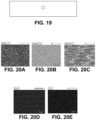
- FIG. 19 is a conceptual diagram illustrating a location within an iron-carbon ribbon at which the data shown in FIGS. 20 A- 20 E was measured.
- FIGS. 20 A- 20 C are scanning electron microscopy wavelength-dispersive spectrometry images of an example iron-carbon ribbon at the location illustrated in FIG. 19 .
- FIGS. 20 D and 20 E are scanning electron microscopy energy-dispersive spectrometry images of an example iron-carbon ribbon at the location illustrated in FIG. 19 .
- FIG. 21 is an image of the iron-carbon ribbon of FIG. 19 .
- FIG. 22 is a conceptual diagram illustrating a location within an iron-carbon ribbon at which the data shown in FIGS. 23 A- 23 E was measured.
- FIGS. 23 A- 23 C are scanning electron microscopy wavelength-dispersive spectrometry images of an example iron-carbon ribbon at the location illustrated in FIG. 22 .
- FIGS. 23 D and 23 E are scanning electron microscopy energy-dispersive spectrometry images of an example iron-carbon ribbon at the location illustrated in FIG. 22 .
- FIG. 24 is an image of the iron-carbon ribbon of FIG. 22 .
- FIG. 25 is a plot of carbon and oxygen concentration as a function of position for the iron-carbon ribbon associated with FIGS. 15 - 24 .
- FIG. 26 is a histogram of particle size after ball milling of iron-carbon ribbons to form iron-carbon powder.
- FIG. 27 shows three scanning electron micrography images of iron-carbon powder.
- FIG. 28 is an x-ray diffraction plot for iron-carbon-nitrogen material showing formation of iron nitride martensite phase.
- FIG. 29 is a plot of magnetization versus magnetic field for the iron-carbon-nitrogen material of FIG. 28 .
- FIG. 30 is an x-ray diffraction plot for iron-carbon-nitrogen ribbons having different carbon content.
- FIG. 31 is an x-ray diffraction plot for an iron-carbon-nitrogen ribbon including 6 atomic percent carbon showing formation of iron nitride martensite.
- FIG. 32 is a plot of magnetization versus magnetic field for the iron-carbon-nitrogen ribbon of FIG. 31 .
- FIG. 33 is an x-ray diffraction plot for iron-carbon-nitrogen ribbons after nitriding for different lengths of time.
- FIG. 34 is an x-ray diffraction plot for a soft magnetic material that includes iron, carbon, and nitrogen.
- FIG. 35 is an x-ray diffraction plot for an iron-carbon-nitrogen material including 6 atomic percent carbon after melt spinning, after ball milling, and after nitriding.
- FIG. 36 is a plot of magnetization versus magnetic field for the iron-carbon nitrogen powder of FIG. 35 .
- FIG. 37 is an x-ray diffraction plot for an iron-carbon-nitrogen ribbon including 6 atomic percent carbon after preparation that include oxidizing and reducing.
- FIG. 38 is a plot of magnetization versus magnetic field for the iron-carbon nitrogen ribbon of FIG. 37 .
- FIG. 39 is an x-ray diffraction plot for an iron-carbon-nitrogen ribbon including 6 atomic percent carbon after preparation that did not include oxidizing and reducing.
- FIG. 40 is a plot of magnetization versus magnetic field for the iron-carbon-nitrogen ribbon of FIG. 39 .
- FIG. 41 is an image of an example FeC ribbon including about 13 atomic percent carbon after nitriding.
- FIG. 42 is an x-ray diffraction plot for a sample prepared from an iron-carbon mixture including about 9 atomic percent carbon after oxidation, reduction, and nitriding.
- FIG. 43 is a plot of magnetization versus magnetic field for the iron-carbon nitrogen ribbon of FIG. 42 .
- FIG. 44 is an x-ray diffraction plot for a sample prepared from an iron-carbon mixture including about 11 atomic percent carbon after oxidation, reduction, and nitriding.
- FIG. 45 is a plot of magnetization versus magnetic field for the iron-carbon nitrogen ribbon of FIG. 44 .
- FIG. 46 is an x-ray diffraction plot for a sample prepared from an iron-carbon mixture including about 13 atomic percent carbon after oxidation, reduction, and nitriding.
- FIG. 47 is a plot of magnetization versus magnetic field for an iron-carbon nitrogen ribbon formed from an iron-carbon mixture including about 11 atomic percent after oxidation, reduction, and nitriding.
- FIG. 48 is a plot of magnetization versus magnetic field for an iron-carbon nitrogen ribbon formed from an iron-carbon mixture including about 11 atomic percent after oxidation, reduction, and nitriding.
- FIG. 49 is a plot of magnetization versus magnetic field for an iron-carbon nitrogen ribbon formed from an iron-carbon mixture including about 13 atomic percent after oxidation, reduction, and nitriding.
- FIG. 50 is a plot of magnetization versus magnetic field for an iron-carbon nitrogen ribbon formed from an iron-carbon mixture including about 13 atomic percent after oxidation, reduction, and nitriding.
- FIG. 51 is a plot of magnetization versus magnetic field for an iron-carbon nitrogen ribbon formed from an iron-carbon mixture including about 13 atomic percent after oxidation, reduction, and nitriding.
- FIG. 52 is a plot of magnetization versus magnetic field for an iron-carbon nitrogen ribbon formed from an iron-carbon mixture including about 13 atomic percent after oxidation, reduction, and nitriding.
- FIG. 53 is an x-ray diffraction plot for an iron-carbon-nitrogen ribbon including 13 atomic percent carbon after preparation that included arc melting of an iron-carbon mixture, melt spinning, and nitriding in ammonia at 150° C. for 10 hours.
- FIG. 54 is a plot of magnetization versus magnetic field for the iron-carbon nitrogen ribbon of FIG. 53 .
- FIG. 55 is an x-ray diffraction plot for an iron-carbon-nitrogen ribbon including 13 atomic percent carbon after preparation that included arc melting of an iron-carbon mixture, melt spinning, and nitriding in ammonia at 150° C. for 10 hours.
- FIG. 56 is a plot of magnetization versus magnetic field for the iron-carbon nitrogen ribbon of FIG. 55 .
- FIG. 57 is an x-ray diffraction plot for an iron-carbon-nitrogen ribbon including 9 atomic percent carbon after preparation that included arc melting of an iron-carbon mixture, melt spinning, and nitriding in ammonia at 150° C. for 10 hours.
- FIG. 58 is a plot of magnetization versus magnetic field for the iron-carbon nitrogen ribbon of FIG. 57 .
- FIG. 59 is an x-ray diffraction plot for an iron-carbon-nitrogen ribbon including 11 atomic percent carbon after preparation that included arc melting of an iron-carbon mixture, melt spinning, and nitriding in ammonia at 150° C. for 10 hours.
- FIG. 60 is a plot of magnetization versus magnetic field for the iron-carbon nitrogen ribbon of FIG. 59 .
- FIG. 61 is an x-ray diffraction plot for an iron-carbon-nitrogen ribbon including 11 atomic percent carbon after preparation that included arc melting of an iron-carbon mixture, melt spinning, and a high temperature nitriding process, with no liquid nitrogen quenching.
- FIG. 62 is an x-ray diffraction plot for an iron-carbon-nitrogen ribbon including 11 atomic percent carbon after preparation that included arc melting of an iron-carbon mixture, melt spinning, and a high temperature nitriding process, with liquid nitrogen quenching after water cooling.
- FIG. 63 is an x-ray diffraction plot for an iron-carbon-nitrogen ribbon including 13 atomic percent carbon after preparation that included arc melting of an iron-carbon mixture, melt spinning, and a high temperature nitriding process, with no liquid nitrogen quenching.
- FIG. 64 is an x-ray diffraction plot for an iron-carbon-nitrogen ribbon including 13 atomic percent carbon after preparation that included arc melting of an iron-carbon mixture, melt spinning, and a high temperature nitriding process, with liquid nitrogen quenching after water cooling.
- the disclosure describes magnetic materials including ⁇ ′′-Fe 16 (N x Z 1-x ) 2 or ⁇ ′-Fe 8 (N x Z 1-x ), or a mixture of at least one of ⁇ ′′-Fe 16 N 2 or ⁇ ′-Fe 8 N and at least one of ⁇ ′′-Fe 16 Z 2 or ⁇ ′-Fe 8 Z, where Z includes at least one of C, B, or O, and x is a number greater than zero and less than one and techniques for forming such materials.
- the magnetic material including ⁇ ′′-Fe 16 (N x Z 1-x ) 2 or ⁇ ′-Fe 8 (N x Z 1-x ), or a mixture of at least one of ⁇ ′′-Fe 16 N 2 or ⁇ ′-Fe 8 N and at least one of ⁇ ′′-Fe 16 Z 2 or ⁇ ′-Fe 8 Z may include a relatively high magnetic saturation, such as greater than about 219 emu/gram, greater than about 242 emu/gram, or greater than about 250 emu/gram.
- the magnetic material including ⁇ ′′-Fe 16 (N x Z 1-x ) 2 or ⁇ ′-Fe 8 (N x Z 1-x ), or a mixture of at least one of ⁇ ′′-Fe 16 N 2 or ⁇ ′-Fe 8 N and at least one of ⁇ ′′-Fe 16 Z 2 or ⁇ ′-Fe 8 Z may include a relatively low coercivity.
- the coercivity of the magnetic material may be less than about 10 Oersted.
- magnetic materials with a coercivity of less than about 10 Oersted may be referred to as soft magnetic materials.
- the combination of relatively high magnetic saturation and relatively low coercivity may make the magnetic material an attractive soft magnetic material for use in transformer and inductor cores, magnetic recording media write heads, microwave devices, magnetic shielding, and the like.
- the magnetic material including ⁇ ′′-Fe 16 (N x Z 1-x ) 2 or ⁇ ′-Fe 8 (N x Z 1-x ), or a mixture of at least one of ⁇ ′′-Fe 16 N 2 or ⁇ ′-Fe 8 N and at least one of ⁇ ′′-Fe 16 Z 2 or ⁇ ′-Fe 8 Z also may possess high magnetic permeability, high frequency response, and the like.
- the soft magnetic materials may be formed using a technique that includes melt spinning of a molten iron-containing material.
- the molten iron-containing material may include elemental Fe, an Fe-based alloy, an Fe—Z mixture, an Fe—N mixture, or an Fe—Z—N mixture.
- the melt-spun material may include elemental Fe, an Fe-based alloy, an Fe—Z mixture, an Fe—N mixture, or an Fe—Z—N mixture.
- the melt-spun material may facilitate further processing of the material to form the soft magnetic material described herein.
- the melt-spun material may facilitate further processing to introduce Fe atoms, Z atoms, or both, to the material due to nano-pores formed in the surface and/or interior of melt-spun ribbons after heat treatment.
- the melt-spun material may be further processed to result in a material including Fe, Z, and N, such as by introducing N atoms, Z atoms, or both.
- the material that includes Fe, Z, and N may in some examples be annealed to form the soft magnetic material that includes ⁇ ′′-Fe 16 (N x Z 1-x ) 2 or ⁇ ′-Fe 8 (N x Z 1-x ), or a mixture of at least one of ⁇ ′′-Fe 16 N 2 or ⁇ ′-Fe 8 N and at least one of ⁇ ′′-Fe 16 Z 2 or ⁇ ′-Fe 8 Z, where Z includes at least one of C, B, or O, and x is a number greater than zero and less than one.
- N and/or Z introduction may be performed at conditions that directly result in the soft magnetic material.
- FIG. 1 is a flow diagram illustrating an example technique for forming a soft magnetic material that includes ⁇ ′′-Fe 16 (N x Z 1-x ) 2 or ⁇ ′-Fe 8 (N x Z 1-x ), or a mixture of at least one of ⁇ ′′-Fe 16 N 2 or ⁇ ′-Fe 8 N and at least one of ⁇ ′′-Fe 16 Z 2 or ⁇ ′-Fe 8 Z, where Z includes at least one of C, B, or O, and x is a number greater than zero and less than one, from a precursor that includes iron and carbon (and/or boron and/or oxygen).
- the following description primarily describes examples in which carbon is used. However, it will be appreciated that similar techniques may be used for boron and/or oxygen.
- the technique of FIG. 1 includes forming a molten mixture including iron and carbon ( 12 ).
- a precursor that includes iron and carbon may be melted in an arc melting furnace.
- the precursor may include, for example, cast iron.
- Cast iron generally includes between about 1.8 weight percent (wt. %) and about 4 wt. % carbon in iron, such as between 2.5 wt. % and about 4 wt. %.
- cast iron powder, pellets, or ingots may be mixed with elemental iron to arrive at a desired carbon concentration.
- the desired carbon concentration may be between about 0.01 atomic percent (at. %) and about 12 at. % carbon, such as between about 2 at. % and about 10 at. % or between about 4 at. % and about 8 at.
- cast iron pellets or powder may be at least partially encapsulated in an iron foil (e.g., an elemental iron foil), where a thickness of the iron foil is selected to result in the desired concentration.
- the iron foil may have a thickness of at least about 100 micrometers.
- the precursor that includes iron and carbon may be placed in the arc melting furnace (or other furnace used to melt the precursor).
- the arc melting furnace may heat the mixture including iron and carbon at a temperature above about 1500° C., or above about 1600° C., or above about 2000° C.
- the precursor then may be mixed to form a molten mixture in which the carbon is substantially homogeneously mixed throughout the iron.
- the molten mixture may be flipped a plurality of times (e.g., about 6 to 10 times) to approach a homogeneous composition.
- the molten mixture may be melt spun to form iron-carbon ribbons ( 14 ).
- the melt spinning parameters may be selected to form ribbons having a selected size (e.g., thickness).
- the melt spinner may be configured with a gap distance of about 0.3 mm and a wheel speed of about 50 Hz.
- the operating temperature of the melt spinner may be selected based on the Fe—C phase diagram.
- the melt spinner may be operated at a temperature of between about 1,300° C. and about 1,500° C.
- the resulting ribbons include a mixture of iron and carbon (e.g., iron-carbon ribbons), and the mixture may be substantially homogeneous (e.g., a concentration of carbon varies by less than about 2 at. % throughout the volume of the ribbons.
- the ribbons may have a thickness between about 30 micrometers and about 60 micrometers.
- the ribbons may include alpha phase iron carbide and gamma phase iron carbide.
- the iron-carbon ribbons then may be nitrided to introduce nitrogen and form iron-nitrogen-carbon ribbons ( 20 ).
- the iron-carbon ribbons may optionally be reduced ( 18 ), and, if reduced, may optionally be oxidized ( 16 ).
- the iron-carbon ribbons may be exposed to a reducing environment ( 18 ) to reduce or substantially eliminate oxides in the iron-carbon ribbons.
- the oxides may be from the precursor material or may form during subsequent processing and/or handling.
- the oxides may include iron oxides, and may affect magnetic properties of the soft magnetic material.
- the oxides may be removed by exposing the iron-carbon ribbons to a reducing environment.
- the reducing environment may include gaseous hydrogen or another reducing gas.
- the reducing environment may include an elevated temperature, such as a temperature between about 300° C. and about 400° C., such as about 350° C.
- the reduction process may be performed for any suitable time, such as at least one hour, or about 2 hours.
- the iron-carbon ribbon prior to exposing the iron-carbon ribbon to the reducing environment ( 18 ), the iron-carbon ribbon optionally may be exposed to an oxidizing environment ( 16 ).
- the oxidizing environment may cause oxides to form on and/or in the iron-carbon ribbon, such as iron oxides. Exposure to the reducing environment ( 18 ) then may remove most or all of these oxides, leaving nano-pores in the surface and/or interior of the iron-carbon ribbon. This may facilitate nitriding of the iron-carbon ribbons to form iron-carbon-nitrogen ribbons.
- the oxidizing environment may include an oxidizing gas, such as air or oxygen, and a high temperature, such as between about 900° C. and about 1000° C., for a sufficient time to form a desired concentration of oxides.
- the time may be about 30 minutes.
- the oxidation ( 16 ) may be omitted and the iron-carbon ribbons may be exposed to the reducing environment ( 18 ).
- the iron-carbon ribbons may be nitrided ( 20 ).
- the iron-carbon ribbons may be exposed to a source of atomic nitrogen, such as nitrogen (N 2 ), gaseous ammonia (NH 3 ), ammonium nitrate (NH 4 NO 3 ; solid), an amide (liquid or solid), or hydrazine (liquid).
- Amides include a C—N—H bond and hydrazine includes an N—N bond.
- Ammonium nitrate, amides and hydrazine may serve as a nitrogen donor for forming the powder including iron nitride.
- Example amides include carbamide ((NH2) 2 CO; also referred to as urea), methanamide (Formula 1), benzamide (Formula 2), and acetamide (Formula 3), although any amide may be used.
- amides may be derived from carboxylic acids by replacing the hydroxyl group of a carboxylic acid with an amine group. Amides of this type may be referred to as acid amides.
- the iron-carbon ribbons and the source of atomic nitrogen also may be heated to decompose the source of atomic nitrogen and enable the nitrogen atoms to diffuse into the iron-carbon ribbons.
- FIG. 2 is a flow diagram illustrating one example technique for nitriding an iron-carbon material to form a soft magnetic material that includes ⁇ ′′-Fe 16 (N x Z 1-x ) 2 or ⁇ ′-Fe 8 (N x Z 1-x ), or a mixture of at least one of ⁇ ′′-Fe 16 N 2 or ⁇ ′-Fe 8 N and at least one of ⁇ ′′-Fe 16 Z 2 or ⁇ ′-Fe 8 Z, where Z includes at least one of C, B, or O, and x is a number greater than zero and less than one.
- the iron-carbon ribbons are exposed to a source of atomic nitrogen at a relatively high temperature ( 22 ).
- the source of atomic nitrogen may be any of the sources mentioned above.
- the relatively high temperature may be between about 600° C. and about 1000° C., such as between about 650° C. and about 900° C., about 600° C., or about 660° C. for at least about 30 minutes, such as about 45 minutes, about 1.5 hours, or about 2 hours.
- the nitriding process forms iron-carbon-nitrogen ribbons.
- the nitrogen may be diffused into the iron-carbon ribbon so that a collective concentration of nitrogen and carbon is between about 8 atomic percent (at. %) and about 14 at. %, such as about 11 at. %.
- the concentration of nitrogen and carbon in iron may be an average concentration and may vary throughout the volume of the iron-carbon-nitrogen ribbon.
- the atomic ratio of iron to the combination of nitrogen plus carbon is between about 11.5:1 (iron:nitrogen+carbon) and about 5.65:1 (iron:nitrogen+carbon).
- the atomic ratio of iron to the combination of nitrogen and carbon may be about 9:1 (iron:nitrogen+carbon), about 8:1 (iron:nitrogen+carbon), or about 6.65:1 (iron:nitrogen+carbon).
- the iron-carbon-nitrogen ribbons may be quenched to room temperature by a quenching medium, such as water, ice water, oil, or brine.
- a quenching medium such as water, ice water, oil, or brine.
- the iron-carbon-nitrogen ribbons then are cryo-treated using a cryogenic coolant, such as liquid nitrogen or liquid helium ( 24 ).
- the cryo-treatment may facilitate formation of martensite phase iron nitride, iron carbide, and/or iron-nitride-carbide.
- the iron-carbon-nitrogen ribbons may be annealed ( 26 ).
- the annealing technique may be performed using a crucible heating stage, a plasma arc lamp, a radiation heat source, such as an infrared heat lamp, an oven, or a closed retort.
- the annealing technique may facilitate magnetic material including at least one of ⁇ ′′-Fe 16 (N x Z 1-x ) 2 phase (where Z includes at least one of C, B, or O) or a mixture of ⁇ ′′-Fe 16 N 2 phase and ⁇ ′′-Fe 16 Z 2 phase.
- the annealing technique allows diffusion of N+ ions, C+ ions, or both within iron to form at least one of ⁇ ′′-Fe 16 N 2 , ⁇ ′′-Fe 16 C 2 , or ⁇ ′′-Fe 16 (N x C 1-x ) 2 .
- annealing at relatively low temperatures allows transformation of partial Fe 8 N disordered phase into ⁇ ′′-Fe 16 N 2 ordered phase.
- annealing at relatively low temperatures is expected to allow transformation of partial Fe 8 C disordered phase into ⁇ ′′-Fe 16 C 2 ordered phase and partial Fe 8 (N x C 1-x ) disordered phase into ⁇ ′′-Fe 16 (N x C 1-x ) 2 ordered phase.
- the annealing technique may be carried out at a temperature below about 300° C., such as between about 120° C. and about 300° C., between about 120° C. and about 220° C., or between about 150° C. and about 220° C.
- the annealing technique may be performed in a nitrogen (N 2 ) or argon (Ar) atmosphere, or in a vacuum or near-vacuum.
- the temperature and duration of the annealing step may be selected based on, for example, a size of the ribbons and diffusion coefficient of nitrogen atoms in iron and carbon atoms in iron at the annealing temperature. Based on these factors, the temperature and duration may be selected to provide sufficient time for nitrogen atoms and carbon atoms to diffuse to locations within the iron-carbon-nitrogen ribbons to form Fe 16 N 2 domains, ⁇ ′′-Fe 16 C 2 domains, and/or ⁇ ′′-Fe 16 (N x C 1-x ) 2 domains.
- the temperature and duration of the annealing technique may be selected based on a desired volume fraction of the respective phase domains in the ribbons. For example, at a selected temperature, a longer annealing technique may result in a higher volume fraction of ⁇ ′′-Fe 16 N 2 , ⁇ ′′-Fe 16 C 2 , and/or ⁇ ′′-Fe 16 (N x C 1-x ) 2 . Similarly, for a given annealing technique duration, a higher temperature may result in a higher volume fraction of ⁇ ′′-Fe 16 N 2 , ⁇ ′′-Fe 16 C 2 , and/or ⁇ ′′-Fe 16 (N x C 1-x ) 2 .
- the additional volume fraction of ⁇ ′′-Fe 16 N 2 , ⁇ ′′-Fe 16 C 2 , and/or ⁇ ′′-Fe 16 (N x C 1-x ) 2 may be limited or eliminated, as the volume fraction of ⁇ ′′-Fe 16 N 2 , ⁇ ′′-Fe 16 C 2 , and/or ⁇ ′′-Fe 16 (N x C 1-x ) 2 reaches a relatively stable value.
- a relatively stable value For example, at a temperature of about 150° C., after about 20 hours, the volume fraction of ⁇ ′′-Fe 16 N 2 reaches a stable value.
- the duration of the annealing step may be at least about 5 hours, such as at least about 20 hours, or between about 5 hours and about 100 hours, or between about 5 hours and about 80 hours or between about 20 hours and about 80 hours, or about 40 hours.
- FIG. 3 is a flow diagram illustrating an example technique for forming a soft magnetic material that includes ⁇ ′′-Fe 16 (N x Z 1-x ) 2 or ⁇ ′-Fe 8 (N x Z 1-x ), or a mixture of at least one of ⁇ ′′-Fe 16 N 2 or ⁇ ′-Fe 8 N and at least one of ⁇ ′′-Fe 16 Z 2 or ⁇ ′-Fe 8 Z, where Z includes at least one of C, B, or O, and x is a number greater than zero and less than one.
- the technique of FIG. 3 includes forming a molten mixture including iron and carbon ( 12 ) and melt spinning the molten mixture including iron and carbon to form iron-carbon ribbons ( 14 ). These steps may be similar to or the same as the corresponding steps described in FIG. 1 . Once the iron-carbon ribbons are formed, the may be ball milled to form iron-carbon powder ( 32 ).
- a milling apparatus may be manipulated to cause agitation of milling media, such as milling spheres, which impact the iron-carbon ribbon and eventually wear the iron-carbon ribbon into powder.
- the milling media may be formed of a sufficiently hard material, such as steel, stainless steel, or the like.
- the material from which the milling media are formed may not chemically react with the iron-carbon ribbon or powder.
- the milling media may have an average diameter between about 5 millimeters (mm) and about 20 mm.
- the iron-carbon powder may have a relatively small average diameter.
- the average diameter may be on the order of hundreds of nanometers, such as between about 100 nm and about 1 micrometer, or between about 300 nm and about 500 nm.
- the iron-carbon powder then may be nitrided ( 38 ).
- the powder optionally may be oxidized to form oxides in and/or on the iron-carbon powder ( 34 ), and/or may be exposed to a reducing atmosphere to reduce any oxides present in the iron-carbon powder ( 36 ).
- Each of these steps may be similar to or substantially the same as the corresponding steps described with reference to FIG. 1 .
- the oxidation ( 34 ) may be omitted and the iron-carbon ribbons may be exposed to the reducing environment ( 36 ).
- the iron-carbon powder may be nitrided using a high temperature technique as described with reference to FIG. 2 or may be nitrided using a relatively low temperature technique.
- the iron-carbon powder may be exposed to a source of atomic nitrogen at a temperature between about 120° C. and about 200° C.
- the nitriding temperature may be between about 140° C. and about 170° C.
- the source of atomic nitrogen may be any of the sources described above with reference to FIGS. 1 and 2 .
- the source of atomic nitrogen is ammonia.
- the iron-carbon-nitrogen powder then may optionally be annealed, as described with reference to FIG. 2 .
- the nitriding at the relatively low temperature may directly form the soft magnetic material described herein and annealing may be omitted.
- FIG. 4 is a flow diagram illustrating an example technique for forming a soft magnetic material that includes ⁇ ′′-Fe 16 (N x Z 1-x ) 2 or ⁇ ′-Fe(N x Z 1-x ), or a mixture of at least one of ⁇ ′′-Fe 6 N 2 or ⁇ ′-Fe 8 N and at least one of ⁇ ′′-Fe 6 Z 2 or ⁇ ′-Fe 8 Z, where Z includes at least one of C, B, or O, and x is a number greater than zero and less than one.
- the technique of FIG. 4 then includes carburizing and nitriding the iron ribbons ( 50 ).
- the carburizing and nitriding are performed together using a source of both carbon and nitrogen atoms.
- urea may be a source of both carbon and nitrogen atoms.
- the carburizing and nitriding are performed together using separate source of carbon and nitrogen atoms.
- the source of nitrogen atoms may be any of the sources described herein, including, for example, diatomic nitrogen (N 2 ), ammonia, ammonium nitrate, an amide (such as urea), or hydrazine.
- the source of carbon atoms may include, for example, carbon monoxide (CO), carbon dioxide (CO 2 ), or methane (CH 4 ), graphite, urea, or the like.
- the carburizing and the nitriding may be performed separately (e.g., sequentially), with either carburizing or nitriding being performed first.
- the iron-containing ribbons may be heated, for example, in a furnace, an autoclave, or the like. Pressure exerted in an autoclave may stabilize ⁇ ′′-Fe 16 (N x Z 1-x ) 2 or ⁇ ′-Fe(N x Z 1-x ), or a mixture of at least one of ⁇ ′′-Fe 6 N 2 or ⁇ ′-Fe 8 N and at least one of ⁇ ′′-Fe 6 Z 2 or ⁇ ′-Fe 8 Z, where Z includes at least one of C, B, or O.
- FIG. 5 is a flow diagram illustrating an example technique for carburizing and nitriding an iron-containing material at relatively high temperatures to form a soft magnetic material that includes ⁇ ′-Fe 16 (N x Z 1-x ) 2 or ⁇ ′-Fe(N x Z 1-x ), or a mixture of at least one of ⁇ ′′-Fe 6 N 2 or ⁇ ′-Fe 8 N and at least one of ⁇ ′′-Fe 6 Z 2 or ⁇ ′-Fe 8 Z, where Z includes at least one of C, B, or O, and x is a number greater than zero and less than one.
- the iron-containing ribbons are exposed to a source of atomic nitrogen and a source of atomic carbon at a relatively high temperature ( 52 ). As described above, this may occur simultaneously or sequentially.
- the sources of atomic nitrogen and atomic carbon may be any of the sources mentioned above.
- the relatively high temperature may be between about 600° C. and about 1000° C., such as between about 650° C. and about 900° C., about 600° C., or about 660° C. for at least about 30 minutes, such as about 45 minutes, about 1.5 hours, or about 2 hours.
- the carburizing and nitriding processes form iron-carbon-nitrogen ribbons.
- the nitrogen and carbon may be diffused into the iron-containing ribbons so that a collective concentration of nitrogen and carbon is between about 8 atomic percent (at. %) and about 14 at. %, such as about 11 at. %.
- the concentration of nitrogen and carbon in iron may be an average concentration and may vary throughout the volume of the iron-carbon-nitrogen ribbon.
- the atomic ratio of iron to the combination of nitrogen plus carbon is between about 11.5:1 (iron:nitrogen+carbon) and about 5.65:1 (iron:nitrogen+carbon).
- the atomic ratio of iron to the combination of nitrogen and carbon may be about 9:1 (iron:nitrogen+carbon), about 8:1 (iron:nitrogen+carbon), or about 6.65:1 (iron:nitrogen+carbon).
- the carbon concentration is about 6 at. %.
- the iron-carbon-nitrogen ribbons may be quenched to room temperature by a quenching medium, such as water, ice water, oil, or brine.
- a quenching medium such as water, ice water, oil, or brine.
- the iron-carbon-nitrogen ribbons then are cryo-treated using a cryogenic coolant, such as liquid nitrogen or liquid helium ( 24 ). This step may be similar to or substantially the same as the corresponding step described with reference to FIG. 2 .
- the iron-carbon-nitrogen ribbons may be annealed ( 26 ). This step may be similar to or substantially the same as the corresponding step described with reference to FIG. 2 .
- FIG. 6 is a flow diagram illustrating an example technique for forming a soft magnetic material that includes ⁇ ′′-Fe 16 (N x Z 1-x ) 2 or ⁇ ′-Fe 8 (N x Z 1-x ), or a mixture of at least one of ⁇ ′′-Fe 16 N 2 or ⁇ ′-Fe 8 N and at least one of ⁇ ′′-Fe 16 Z 2 or ⁇ ′-Fe 8 Z, where Z includes at least one of C, B, or O, and x is a number greater than zero and less than one.
- the technique of FIG. 6 includes forming a molten mixture including iron ( 42 ) and melt spinning the molten mixture including iron to form iron-containing ribbons ( 44 ). These steps may be similar to or the same as the corresponding steps described in FIG. 4 . Once the iron-containing ribbons are formed, the ribbons may be ball milled to form iron-containing powder ( 62 ).
- a milling apparatus may be manipulated to cause agitation of milling media, such as milling spheres, which impact the iron-containing ribbon and eventually wear the iron-containing ribbon into powder.
- the milling media may be formed of a sufficiently hard material, such as steel, stainless steel, or the like.
- the material from which the milling media are formed may not chemically react with the iron-containing ribbon or powder.
- the milling media may have an average diameter between about 5 millimeters (mm) and about 20 mm.
- the iron-containing powder may have a relatively small average diameter.
- the average diameter may be on the order of hundreds of nanometers, such as between about 100 nm and about 1 micrometer, or between about 300 nm and about 500 nm.
- the iron-containing powder then may be carburized and nitrided ( 68 ).
- the powder optionally may be oxidized to form oxides in and/or on the iron-containing powder ( 64 ), and/or may be exposed to a reducing atmosphere to reduce any oxides present in the iron-containing powder ( 66 ).
- Each of these steps may be similar to or substantially the same as the corresponding steps described with reference to FIGS. 1 and 4 .
- the iron-containing powder may be carburized and nitrided using a high temperature technique as described with reference to FIG. 5 or may be carburized and nitrided using a relatively low temperature technique.
- the iron-containing powder may be exposed to a source of atomic nitrogen and a source of atomic carbon (simultaneously or sequentially).
- the iron-containing powder may be exposed to the source of atomic nitrogen at a temperature between about 120° C. and about 200° C., such as between about 140° C. and about 170° C.
- the iron-containing powder may be exposed to the source of atomic carbon at a temperature between about 700° C. and about 1100° C., such as between about 700° C. and about 750° C., or between about 960° C. and about 1100° C.
- the source of atomic nitrogen may be any of the sources described above with reference to FIGS. 1 and 2
- the source of atomic carbon may be any of the sources described above with reference to FIGS. 4 and 5 .
- the source of atomic nitrogen is ammonia, or the source of both atomic nitrogen and atomic carbon is urea.
- the iron-carbon-nitrogen powder then may optionally be annealed, as described with reference to FIGS. 2 and 5 .
- the carburizing and nitriding at the relatively low temperature may directly form the soft magnetic material described herein and annealing may be omitted.
- FIG. 7 is a flow diagram illustrating an example technique for forming a soft magnetic material that includes ⁇ ′′-Fe 16 (N x Z 1-x ) 2 or ⁇ ′-Fe 8 (N x Z 1-x ), or a mixture of at least one of ⁇ ′-Fe 16 N 2 or ⁇ ′-Fe 8 N and at least one of ⁇ ′-Fe 16 Z 2 or ⁇ ′-Fe 8 Z, where Z includes at least one of C, B, or O, and x is a number greater than zero and less than one.
- FIG. 7 includes forming a molten mixture including iron and nitrogen ( 72 ), melt spinning the molten mixture including iron and nitrogen to form iron-nitrogen ribbons ( 74 ), optionally oxidizing the iron-nitrogen ribbons ( 76 ), and optionally reducing the iron-nitrogen ribbons ( 78 ).
- Each of these steps may be similar to or substantially the same as corresponding steps described above with reference to FIGS. 1 - 3 , except that the material is an iron-nitrogen material, not an iron-carbon material.
- the technique of FIG. 7 then includes carburizing the iron-nitrogen ribbons ( 80 ) by exposing the iron-nitrogen ribbons to a source of carbon atoms.
- the source of carbon atoms may include, for example, carbon monoxide (CO), carbon dioxide (CO 2 ), or methane (CH 4 ), graphite, urea, or the like.
- the iron-nitrogen ribbons may be heated, for example, in a furnace, an autoclave, or the like. Pressure exerted in an autoclave may stabilize ⁇ ′-Fe 16 (N x Z 1-x ) 2 or ⁇ ′-Fe 8 (N x Z 1-x ), or a mixture of at least one of ⁇ ′-Fe 16 N 2 or ⁇ ′-Fe 8 N and at least one of ⁇ ′-Fe 16 Z 2 or ⁇ ′-Fe 8 Z, where Z includes at least one of C, B, or 0.
- the carburizing may be performed at a relatively high temperature, such as between about 960° C. and about 1100° C., or a relatively lower temperature, such as between about 700° C. and about 750° C.
- FIG. 8 is a flow diagram illustrating an example technique for carburizing an iron-nitrogen material at relatively high temperatures to form a soft magnetic material that includes ⁇ ′′-Fe 16 (N x Z 1-x ) 2 or ⁇ ′-Fe 8 (N x Z 1-x ), or a mixture of at least one of ⁇ ′′-Fe 16 N 2 or ⁇ ′-Fe 8 N and at least one of ⁇ ′′-Fe 16 Z 2 or ⁇ ′-Fe 8 Z, where Z includes at least one of C, B, or O, and x is a number greater than zero and less than one.
- the iron-nitrogen ribbons are exposed to a source of atomic carbon at a relatively high temperature ( 82 ).
- the iron-nitrogen material may be exposed to the source of atomic carbon for at least about 30 minutes, such as about 45 minutes, about 1.5 hours, or about 2 hours.
- the carburizing process forms iron-carbon-nitrogen ribbons.
- the carbon may be diffused into the iron-nitrogen ribbons so that a collective concentration of nitrogen and carbon is between about 8 atomic percent (at. %) and about 14 at. %, such as about 11 at. %.
- the concentration of nitrogen and carbon in iron may be an average concentration and may vary throughout the volume of the iron-carbon-nitrogen ribbon.
- the atomic ratio of iron to the combination of nitrogen plus carbon is between about 11.5:1 (iron:nitrogen+carbon) and about 5.65:1 (iron:nitrogen+carbon).
- the atomic ratio of iron to the combination of nitrogen and carbon may be about 9:1 (iron:nitrogen+carbon), about 8:1 (iron:nitrogen+carbon), or about 6.65:1 (iron:nitrogen+carbon).
- the carbon concentration is about 6 at. %.
- the iron-carbon-nitrogen ribbons may be quenched to room temperature by a quenching medium, such as water, ice water, oil, or brine.
- a quenching medium such as water, ice water, oil, or brine.
- the iron-carbon-nitrogen ribbons then are cryo-treated using a cryogenic coolant, such as liquid nitrogen or liquid helium ( 24 ). This step may be similar to or substantially the same as the corresponding step described with reference to FIGS. 2 and 5 .
- the iron-carbon-nitrogen ribbons may be annealed ( 26 ). This step may be similar to or substantially the same as the corresponding step described with reference to FIGS. 2 and 5 .
- FIG. 9 is a flow diagram illustrating an example technique for forming a soft magnetic material that includes ⁇ ′′-Fe 16 (N x Z 1-x ) 2 or ⁇ ′-Fe 8 (N x Z 1-x ), or a mixture of at least one of ⁇ ′′-Fe 16 N 2 or ⁇ ′-Fe 8 N and at least one of ⁇ ′′-Fe 16 Z 2 or ⁇ ′-Fe 8 Z, where Z includes at least one of C, B, or O, and x is a number greater than zero and less than one.
- the technique of FIG. 7 the technique of FIG.
- a milling apparatus may be manipulated to cause agitation of milling media, such as milling spheres, which impact the iron-containing ribbon and eventually wear the iron-containing ribbon into powder.
- the milling media may be formed of a sufficiently hard material, such as steel, stainless steel, or the like.
- the material from which the milling media are formed may not chemically react with the iron-containing ribbon or powder.
- the milling media may have an average diameter between about 5 millimeters (mm) and about 20 mm.
- the iron-containing powder may have a relatively small average diameter.
- the average diameter may be on the order of hundreds of nanometers, such as between about 100 nm and about 1 micrometer, or between about 300 nm and about 500 nm.
- the iron-nitrogen powder then may be carburized ( 98 ).
- the powder optionally may be oxidized to form oxides in and/or on the iron-nitrogen powder ( 94 ), and/or may be exposed to a reducing atmosphere to reduce any oxides present in the iron-nitrogen powder ( 96 ).
- Each of these steps may be similar to or substantially the same as the corresponding steps described with reference to FIGS. 1 , 4 , and 7 .
- the iron-nitrogen powder may be carburized using a high temperature technique as described with reference to FIG. 8 or may be carburized using a relatively low temperature technique.
- the iron-nitrogen powder may be exposed to a source of atomic carbon at a temperature between about 700° C. and about 750° C.
- the source of atomic carbon may be any of the sources described above with reference to FIGS. 4 and 5 .
- the source of atomic carbon is methane.
- the iron-carbon-nitrogen powder then may optionally be annealed, as described with reference to FIGS. 2 , 5 , and 8 .
- the carburizing at the relatively low temperature may directly form the soft magnetic material described herein and annealing may be omitted.
- FIG. 10 is a conceptual diagram that shows an ⁇ ′′-Fe 16 X 2 unit cell.
- the X atoms are aligned along the (002) (iron) crystal planes.
- the X atoms may include at least one of N, C, B, or O.
- the iron nitride unit cell is distorted such that the length of the unit cell along the ⁇ 001> axis is approximately 6.28 angstroms ( ⁇ ) while the length of the unit cell along the ⁇ 010> and ⁇ 100> axes is approximately 5.72 ⁇ .
- the ⁇ ′′-Fe 16 N 2 unit cell may be referred to as a bct unit cell when in the strained state.
- the ⁇ 001> axis may be referred to as the c-axis of the unit cell.
- the c-axis may be the magnetic easy axis of the ⁇ ′′-Fe 6 N 2 unit cell. In other words, ⁇ ′′-Fe 6 N 2 crystals exhibit magnetic anisotropy.
- ⁇ ′′-Fe 6 N 2 has high saturation magnetization and magnetic anisotropy constant.
- the high saturation magnetization and magnetic anisotropy constants result in a magnetic energy product that may be higher than rare earth magnets. Additionally, iron and nitrogen are abundant elements, and thus are relatively inexpensive and easy to procure.
- ⁇ ′′-Fe 16 N 2 may be about 1.6 ⁇ 10 7 erg/cm 3 .
- ⁇ ′′-Fe 16 N 2 also has a relatively high theoretical magnetic saturation moment of about 2.3 Bohr magnetons per iron atom B/Fe.
- ⁇ ′′-Fe 6 Z 2 may be a hard magnetic material when the Z atoms are ordered within the iron crystal lattice.
- the Z atoms (C, B, or O) in ordered ⁇ ′′-Fe 6 Z 2 may be positioned at octahedral interstitial sites within the iron crystal.
- the lattice parameters may be different than the lattice parameters of ⁇ ′′-Fe 16 N 2 .
- the presence of carbon atoms is expected to reduce the distance between the C atoms and the surrounding Fe atoms lying in the (002) (iron) crystal planes from 3.74 Angstroms to 3.68 Angstroms. This is expected to increase p-d mixing, which is expected to increase bandwidth and lower the density of states. This is expected to reduce the magnetocrystalline anisotropy of ⁇ ′′-Fe 16 C 2 to a negative value. Similar results may be expected for B and O atoms.
- Ordered ⁇ ′′-Fe 16 Z 2 may exhibit magnetocrystalline anisotropy with a magnetic easy axis lying in the a-b plane (e.g., [100]; perpendicular to the c-axis).
- the direction of magnetocrystalline anisotropy in ⁇ ′′-Fe 6 Z 2 may be substantially perpendicular to the direction of magnetocrystalline anisotropy in ⁇ ′′-Fe 16 N 2 .
- the magnetocrystalline anisotropy in ordered ⁇ ′′-Fe 16 C 2 may be about ⁇ 1.4 ⁇ 10 7 erg/cm 3 .
- ⁇ ′′-Fe 16 C 2 also has a relatively high theoretical magnetic saturation moment of about 2.1 ⁇ B /Fe.
- a magnetic material including a volume ratio of ⁇ ′′-Fe 6 N 2 to ⁇ ′′-Fe 16 C 2 of about 4.667:5.333 may have a magnetic anisotropy of about 0 (e.g., less than about 10 Oersteds) and a theoretical magnetic saturation moment of about 2.2 ⁇ B /Fe.
- a mixture of predetermined volumes of ⁇ ′′-Fe 6 N 2 domains and ⁇ ′′-Fe 16 C 2 domains may produce a soft magnetic material with a magnetocrystalline anisotropy value of near zero and a relatively high magnetic saturation moment. Similar results may be expected when B, O, or both are substituted for C, based on the similar atomic radii of C, B, and O.
- FIG. 11 is a conceptual diagram illustrating a soft magnetic material 100 including domains of ⁇ ′′-Fe 16 N 2 102 and domains of ⁇ ′′-Fe 16 Z 2 104 , where Z includes at least one of C, B, or O.
- discrete domains of ⁇ ′′-Fe 16 N 2 102 may be present, along with discrete domains of ⁇ ′′-Fe 16 Z 2 104 .
- the easy axes of the domains of ⁇ ′′-Fe 16 N 2 102 are illustrated as being oriented substantially vertically in FIG.
- the respective easy axes of the respective domains of ⁇ ′′-Fe 16 N 2 102 may be substantially randomly distributed.
- the respective easy axes of the respective domains of ⁇ ′′-Fe 16 Z 2 104 may be substantially randomly distributed. This also may lead to a soft magnetic material 100 with high saturation magnetization and low magnetocrystalline anisotropy.
- soft magnetic material 100 including a mixture of domains of ⁇ ′′-Fe 16 N 2 12 and domains of ⁇ ′′-Fe 16 Z 2 104 may not include only domains of ⁇ ′′-Fe 16 N 2 102 and domains of ⁇ ′′-Fe 16 Z 2 104 .
- soft magnetic material 100 may include at least one Fe 16 (N x Z 1-x ) 2 phase domain in addition to domains of ⁇ ′′-Fe 16 N 2 102 and domains of ⁇ ′′-Fe 16 Z 2 104 .
- the size of the domains may be between about 1 nm and about 100 micrometers. The average domain size distribution may influence the permeability of the material as evidenced by the slope of the hysteresis loop.
- soft magnetic material 100 including a mixture of domains of ⁇ ′′-Fe 16 N 2 102 and domains of ⁇ ′′-Fe 16 Z 2 104 may include other iron phases, other iron nitride phases, other iron carbide phases, or other phases including other constituents (e.g., dopants or impurities) present in the soft magnetic material.
- Dopants may include, for example, Cu, Co, Ti, Mn, Al, V, Cr, Zn, Ga, Ge, Zr, nNb, Mo, P, Si, Mg, or the like.
- Dopants may be used to fine tune the microstructure and magnetocrystalline anisotropy of the soft magnetic material.
- the dopants may be present in an amount between about 0.1 atomic percent and about 15 atomic percent.
- the structure shown in FIG. 11 may be formed by low temperature carburizing and/or nitriding an iron-containing material, and/or annealing a material including a mixture of iron, carbon, and nitrogen in selected ratios to convert the mixture of iron, carbon, and nitrogen to domains of ⁇ ′′-Fe 6 N 2 102 and domains of ⁇ ′′-Fe 16 Z 2 104 .
- the structure shown in FIG. 11 may be formed by low temperature carburizing and/or nitriding an iron-containing material, and/or annealing a material including a mixture of iron, carbon, and nitrogen in selected ratios to convert the mixture of iron, carbon, and nitrogen to domains of ⁇ ′′-Fe 6 N 2 102 and domains of ⁇ ′′-Fe 16 Z 2 104 .
- 11 may be formed by first forming particles (e.g., ribbons or powder) including ⁇ ′′-Fe 6 N 2 and particles including ⁇ ′′-Fe 6 Z 2 (e.g., using melt spinning and/or milling), then consolidating the ribbons or particles to form the material including domains of ⁇ ′′-Fe 16 N 2 102 and domains of ⁇ ′′-Fe 16 Z 2 104 .
- particles e.g., ribbons or powder
- particles including ⁇ ′′-Fe 6 Z 2 e.g., using melt spinning and/or milling
- a material may include one or more crystals of ⁇ ′′-Fe 16 (N x Z 1-x ) 2 , where Z includes at least one of C, B, or O, and x is a number greater than 0 and less than 1.
- the iron, nitrogen, and Z atoms form a crystalline structure in which some interstitial locations are filled by nitrogen atoms and some interstitial locations are filled by Z atoms.
- FIG. 10 illustrates an example ⁇ ′′-Fe 6 X 2 unit cell, as described above. The unit cell in FIG.
- X atoms 1 X atom is fully in the unit cell, and 4 X atoms are partially in the unit cell).
- ⁇ ′′-Fe 16 (N x Z 1-x ) 2 at least some of the X atoms may be N atoms, and at least some of the X atoms may be Z (C, B, or O) atoms.
- ⁇ ′′-Fe 16 (N x Z 1-x ) 2 may not include some N atoms and some Z atoms in each unit cell (e.g., some unit cells may include only N atoms and some unit cells may include only Z atoms), when averaged over the volume of the soft magnetic material, the ratio of Fe to N to Z atoms may be expressed by the chemical formula Fe 16 (N x Z 1-x ) 2 , where x is greater than 0 and less than 1.
- X may be about 0.5 or about 0.4667.
- the soft magnetic material including Fe 16 (N x Z 1-x ) 2 may not include only Fe 16 (N x Z 1-x ) 2 .
- the soft magnetic material may include at least one ⁇ ′′-Fe 6 N 2 phase domain or at least one ⁇ ′′-Fe 6 Z 2 domain in addition to at least one Fe 16 (N x Z 1-x ) 2 phase domain.
- the soft magnetic material including Fe 16 (N x Z 1-x ) 2 may include other iron phases, other iron nitride phases, other iron carbide phases, or other phase including other constituents (e.g., dopants or impurities) present in the soft magnetic material.
- a soft magnetic material including at least one ⁇ ′′-Fe 16 (N x Z 1-x ) 2 phase domain may include at least about 35 volume percent ⁇ ′′-Fe 16 (N x Z 1-x ) 2 phase domain(s).
- the soft magnetic material may include at least about 40 volume percent, at least about 50 volume percent, or at least about 60 volume percent ⁇ ′′-Fe 16 (N x Z 1-x ) 2 phase domain(s).
- a soft magnetic material including a mixture of ⁇ ′′-Fe 16 N 2 and ⁇ ′′-Fe 16 Z 2 may include at least about 35 volume percent of the combination of ⁇ ′′-Fe 16 N 2 and ⁇ ′′-Fe 16 Z 2 phase domains.
- the soft magnetic material may include at least about 40 volume percent, at least about 50 volume percent, or at least about 60 volume percent of the combination of ⁇ ′′-Fe 16 N 2 and ⁇ ′′-Fe 16 Z 2 phase domains.
- the soft magnetic material including Fe 16 (N x Z 1-x ) 2 or a mixture of ⁇ ′′-Fe 16 N 2 and ⁇ ′′-Fe 16 Z 2 may have a saturation magnetization of at least about 219 emu/gram, which is the saturation magnetization of pure iron.
- the soft magnetic material including Fe 16 (N x Z 1-x ) 2 or a mixture of ⁇ ′′-Fe 16 N 2 and ⁇ ′′-Fe 16 Z 2 may have a saturation magnetization of at least about 242 emu/gram, which is the saturation magnetization of Fe 65 Co 35 .
- the soft magnetic material including Fe 16 (N x Z 1-x ) 2 or a mixture of ⁇ ′′-Fe 16 N 2 and ⁇ ′′-Fe 16 Z 2 may have a saturation magnetization of at least about 250 emu/gram.
- the soft magnetic material including Fe 16 (N x Z 1-x ) 2 or a mixture of ⁇ ′′-Fe 16 N 2 and ⁇ ′′-Fe 16 Z 2 may have a soft magnetic coercivity of less than or equal to about 10 Oersteds.
- the soft magnetic material including ⁇ ′′-Fe 16 (N x Z 1-x ) 2 or a mixture of ⁇ ′′-Fe 16 N 2 and ⁇ ′′-Fe 16 Z 2 also may possess high magnetic permeability, high frequency response, or the like.
- the soft magnetic materials described herein may be formed into bulk soft magnetic materials by assembling multiple ribbons, powders, or the like.
- the ribbons, powders, or the like may be assembled using compaction, resins or adhesives, or the like.
- the ribbons, powders, or the like may be assembled in a relatively low temperature process, e.g., a process performed at less than about 200° C., to reduce or substantially avoid affecting the magnetic properties of the soft magnetic materials.
- the bulk soft magnetic material may be formed with any desired shape during the assembly process, e.g., depending on the final use of the bulk soft magnetic material.
- the soft magnetic materials that are assembled into bulk soft magnetic materials may include oxide coatings or shells.
- the material is oxidized and, optionally, reduced.
- the oxidation may form an oxide (e.g., iron oxide) outer layer or shell, which may be left (i.e., not reduced) or may be not fully reduced (i.e., reduction is performed, but at conditions that result in some oxide remaining).
- the material may be oxidized after forming the soft magnetic material including ⁇ ′′-Fe 6 (N x Z 1-x ) 2 or a mixture of ⁇ ′′-Fe 16 N 2 and ⁇ ′′-Fe 6 Z 2 , e.g., using an intentional reaction process or by exposing the material to ambient air.
- the oxide coating or shell may be useful when the bulk soft magnetic material is used in some applications, e.g., high frequency electromagnetic applications.
- a powder including a soft magnetic material including ⁇ ′′-Fe 16 (N x Z 1-x ) 2 or a mixture of ⁇ ′′-Fe 16 N 2 and ⁇ ′′-Fe 16 Z 2 may be used for electromagnetic shielding.
- the powder may be spray coated on a component with any selected shape to form an electromagnetic shield for all or part of the component.
- a method comprising: forming a soft magnetic material by a technique comprising melt spinning, wherein the soft magnetic material comprises at least one of: at least one of an ⁇ ′′-Fe 6 (N x Z 1-x ) 2 phase domain or an ⁇ ′-Fe 8 (N x Z 1-x ), wherein Z includes at least one of C, B, or O, and wherein x is a number greater than zero and less than one; or at least one of an ⁇ ′′-Fe 16 N 2 phase domain or an ⁇ ′-Fe 8 N phase domain, and at least one of an ⁇ ′′-Fe 16 Z 2 phase domain or an ⁇ ′-Fe 8 Z phase domain.
- Clause 2 The method of clause 1, wherein forming the soft magnetic material by the technique comprising melt spinning comprises: forming a molten mixture comprising iron and carbon; melt spinning the molten mixture comprising iron and carbon to form iron-carbon ribbons; and nitriding the iron-carbon ribbons to form an iron-carbon-nitrogen material.
- Clause 3 The method of clause 2, wherein nitriding the iron-carbon ribbons comprises exposing the iron-carbon ribbons to a nitrogen source at a temperature of between about 650° C. and about 900° C.
- Clause 4 The method of clause 3, wherein the nitrogen source comprises at least one of ammonia, ammonium nitrate, urea, an amide, or hydrazine.
- Clause 5 The method of any one of clauses 2 to 4, further comprising cryo-treating the iron-carbon-nitrogen material in liquid nitrogen.
- Clause 6 The method of any one of clauses 2 to 5, further comprising annealing the iron-carbon-nitrogen material in a nitrogen-containing atmosphere at a temperature between about 100° C. and about 210° C. for between about 5 hours and about 100 hours.
- Clause 7 The method of any one of clauses 2 to 6, further comprising, prior to nitriding the iron-carbon ribbons, exposing the iron-carbon ribbons to a reducing atmosphere to reduce a concentration of oxides in the iron-carbon ribbon.
- Clause 8 The method of clause 7, further comprising, prior to exposing the iron-carbon ribbons to the reducing atmosphere, exposing the iron-carbon ribbons to an oxidizing atmosphere to form oxides in the iron-carbon ribbons, wherein exposing the iron-carbon ribbons to the reducing atmosphere removes at least some of the oxides and forms pores in the iron-carbon ribbons.
- Clause 9 The method of any one of clauses 2 to 8, further comprising, prior to nitriding the iron-carbon ribbons, leaching some carbon from at least a surface of the iron-carbon ribbons to create porosity in the iron-carbon ribbons.
- Clause 10 The method of clause 1, wherein forming the soft magnetic material by the technique comprising melt spinning comprises: forming a molten mixture comprising iron and carbon; melt spinning the molten mixture comprising iron and carbon to form iron-carbon ribbons; ball milling the iron-carbon ribbons to form iron-carbon powder; and nitriding the iron-carbon powder.
- Clause 11 The method of clause 10, wherein nitriding the iron-carbon powder comprises exposing the iron-carbon powder to a nitrogen source at a temperature between about 100° C. and about 210° C. for between about 5 hours and about 100 hours.
- Clause 12 The method of clause 11, wherein the nitrogen source comprises at least one of ammonia, ammonium nitrate, urea, an amide, or hydrazine.
- Clause 13 The method of any one of clauses 10 to 12, further comprising, prior to nitriding the iron-carbon powder, exposing the iron-carbon powder to a reducing atmosphere to reduce a concentration of oxides in the iron-carbon powder.
- Clause 14 The method of clause 13, further comprising, prior to exposing the iron-carbon powder to the reducing atmosphere, exposing the iron-carbon powder to an oxidizing atmosphere to form oxides in the iron-carbon powder, wherein exposing the iron-carbon powder to the reducing atmosphere removes at least some of the oxides and forms pores in the iron-carbon powder.
- Clause 15 The method of any one of clauses 10 to 14, further comprising, prior to nitriding the iron-carbon powder, leaching some carbon from at least a surface of the iron-carbon powder to create porosity in the iron-carbon powder.
- Clause 16 The method of any one of claims 2 to 15 , wherein forming the molten mixture comprising iron and carbon comprises melting cast iron.
- Clause 17 The method of clause 16, wherein the cast iron is encapsulated in elemental iron.
- Clause 18 The method of any one of clauses 2 to 17, wherein the molten mixture comprises a substantially homogeneous distribution of carbon.
- Clause 19 The method of clause 1, wherein forming the soft magnetic material by the technique comprising melt spinning comprises: forming a molten mixture comprising iron; melt spinning the molten mixture comprising iron and carbon to form iron ribbons; and carburizing and nitriding the iron ribbons to form an iron-carbon-nitrogen material.
- Clause 20 The method of clause 19, wherein carburizing and nitriding the iron ribbons comprises exposing the iron ribbons to a nitrogen source at a temperature of between about 650° C. and about 900° C.
- Clause 21 The method of clause 20, wherein the nitrogen source comprises at least one of ammonia, ammonium nitrate, urea, an amide, or hydrazine.
- Clause 22 The method of any one of clauses 19 to 21, wherein carburizing and nitriding the iron ribbons comprises exposing the iron ribbons to a carbon source.
- Clause 23 The method of clause 22, wherein the carbon source comprises at least one of urea, graphite, carbon monoxide, carbon dioxide, or methane.
- Clause 24 The method of clause 19, wherein carburizing and nitriding the iron ribbons comprises exposing the iron ribbons to a carbon-nitrogen source.
- Clause 25 The method of clause 24, wherein the carbon-nitrogen source comprises a carbamide.
- Clause 26 The method of any one of clauses 19 to 25, further comprising cryo-treating the iron-carbon-nitrogen material in liquid nitrogen.
- Clause 27 The method of any one of claims 19 to 26 , further comprising annealing the iron-carbon-nitrogen material in a nitrogen-containing atmosphere at a temperature between about 100° C. and about 210° C. for between about 5 hours and about 100 hours.
- Clause 28 The method of any one of clauses 19 to 27, further comprising, prior to carburizing and nitriding the iron ribbons, exposing the iron ribbons to a reducing atmosphere to reduce a concentration of oxides in the iron ribbon.
- Clause 29 The method of clause 28, further comprising, prior to exposing the iron ribbons to the reducing atmosphere, exposing the iron ribbons to an oxidizing atmosphere to form oxides in the iron ribbons, wherein exposing the iron ribbons to the reducing atmosphere removes at least some of the oxides and forms pores in the iron ribbons.
- Clause 30 The method of any one of clauses 19 to 29, further comprising, prior to carburizing and nitriding the iron ribbons, leaching some carbon from at least a surface of the iron ribbons to create porosity in the iron ribbons.
- Clause 31 The method of clause 1, wherein forming the soft magnetic material by the technique comprising melt spinning comprises: forming a molten mixture comprising iron; melt spinning the molten mixture comprising iron to form iron ribbons; ball milling the iron ribbons to form iron powder; and carburizing and nitriding the iron powder to form an iron-carbon-nitrogen material.
- Clause 32 The method of clause 31, wherein nitriding the iron-carbon powder comprises exposing the iron-carbon powder to a nitrogen source at a temperature between about 100° C. and about 210° C. for between about 5 hours and about 100 hours.
- Clause 33 The method of clause 32, wherein the nitrogen source comprises ammonia, ammonium nitrate, urea, an amide, or hydrazine.
- Clause 34 The method of any one of clauses 31 to 33, wherein carburizing and nitriding the iron ribbons comprises exposing the iron ribbons to a carbon source.
- Clause 35 The method of clause 34, wherein the carbon source comprises at least one of urea, graphite, carbon monoxide, carbon dioxide, or methane.
- Clause 36 The method of clause 31, wherein carburizing and nitriding the iron ribbons comprises exposing the iron ribbons to a carbon-nitrogen source.
- Clause 37 The method of clause 36, wherein the carbon-nitrogen source comprises a carbamide.
- Clause 38 The method of any one of clauses 31 to 37, further comprising, prior to carburizing and nitriding the iron powder, exposing the iron powder to a reducing atmosphere to reduce a concentration of oxides in the iron powder.
- Clause 39 The method of clause 38, further comprising, prior to exposing the iron powder to the reducing atmosphere, exposing the iron powder to an oxidizing atmosphere to form oxides in the iron powder, wherein exposing the iron powder to the reducing atmosphere removes at least some of the oxides and forms pores in the iron powder.
- Clause 40 The method of clause 1, wherein forming the soft magnetic material by the technique comprising melt spinning comprises: forming a molten mixture comprising iron and nitrogen; melt spinning the molten mixture comprising iron and nitrogen to form iron-nitrogen ribbons; and carburizing the iron-nitrogen ribbons to form an iron-carbon-nitrogen material.
- Clause 41 The method of clause 40, wherein nitriding the iron-nitrogen ribbons comprises exposing the iron-nitrogen ribbons to a carbon source.
- Clause 42 The method of clause 41, wherein the carbon source comprises at least one of urea, graphite, carbon monoxide, carbon dioxide, or methane.
- Clause 43 The method of any one of clauses 40 to 42, further comprising cryo-treating the iron-carbon-nitrogen in liquid nitrogen.
- Clause 44 The method of any one of clauses 40 to 43, further comprising annealing the iron-carbon-nitrogen material in a nitrogen-containing atmosphere at a temperature between about 100° C. and about 210° C. for between about 5 hours and about 100 hours.
- Clause 45 The method of any one of clauses 40 to 44, further comprising, prior to carburizing the iron-nitrogen ribbons, exposing the iron-nitrogen ribbons to a reducing atmosphere to reduce a concentration of oxides in the iron-nitrogen ribbon.
- Clause 46 The method of clause 45, further comprising, prior to exposing the iron-nitrogen ribbons to the reducing atmosphere, exposing the iron-nitrogen ribbons to an oxidizing atmosphere to form oxides in the iron-nitrogen ribbons, wherein exposing the iron-nitrogen ribbons to the reducing atmosphere removes at least some of the oxides and forms pores in the iron-nitrogen ribbons.
- Clause 47 The method of any one of clause 40 to 46, further comprising, prior to carburizing the iron-nitrogen ribbons, leaching some nitrogen from at least a surface of the iron-nitrogen ribbons to create porosity in the iron-nitrogen ribbons.
- Clause 48 The method of clause 1, wherein forming the soft magnetic material by the technique comprising melt spinning comprises: forming a molten mixture comprising iron and nitrogen; melt spinning the molten mixture comprising iron and nitrogen to form iron-nitrogen ribbons; ball milling the iron-nitrogen ribbons to form iron-nitrogen powder; and carburizing the iron-nitrogen powder.
- Clause 49 The method of clause 48, wherein carburizing the iron-nitrogen powder comprises exposing the iron-carbon powder to a carbon source.
- Clause 50 The method of clause 49, wherein the carbon source comprises at least one of urea, graphite, carbon monoxide, carbon dioxide, or methane.
- Clause 51 The method of any one of clauses 48 to 50, further comprising, prior to carburizing the iron-nitrogen powder, exposing the iron-nitrogen powder to a reducing atmosphere to reduce a concentration of oxides in the iron-nitrogen powder.
- Clause 52 The method of clause 51, further comprising, prior to exposing the iron-nitrogen powder to the reducing atmosphere, exposing the iron-nitrogen powder to an oxidizing atmosphere to form oxides in the iron-nitrogen powder, wherein exposing the iron-nitrogen powder to the reducing atmosphere removes at least some of the oxides and forms pores in the iron-nitrogen powder.
- Clause 53 The method of any one of clauses 48 to 52, further comprising, prior to carburizing the iron-nitrogen powder, leaching some carbon from at least a surface of the iron-nitrogen powder to create porosity in the iron-nitrogen powder.
- Clause 54 The method of any one of claims 40 to 53 , wherein the molten mixture comprises a substantially homogeneous distribution of nitrogen.
- Cast iron ingots with known carbon concentrations were wrapped in pure iron foils with selected thicknesses to achieve a desired carbon concentration.
- the ingots were melted in an arc melting machine (a SP-MSM20-7 compact vacuum arc melting system, available from MTI Corporation) at a temperature of about 1600° C. at 700 mTorr. Between 6 and 10 flips of the molten material were made to approach a homogeneous composition.
- the molten material was then melt spun using a Melt Spinner SC, available from Edmund Buhler GmbH.
- the gap distance was set at 0.3 mm and the wheel speed was about 50 Hz.
- the melting temperature was between about 1300° C. and about 1500° C., depending on the carbon content.
- FIGS. 12 and 13 The resulting ribbons are shown in FIGS. 12 and 13 .
- the ribbons had a thickness between about 30 micrometers and about 60 micrometers.
- the ribbons exhibited strong ⁇ -Fe(C) peaks when the carbon concentration was high (e.g., about 8 atomic percent).
- the ⁇ -Fe(C) peaks overlapped the ⁇ -Fe(C) at lower carbon concentrations (e.g., 4.5 atomic percent).
- FIG. 14 is an x-ray diffraction plot for iron-carbon ribbons having different carbon content (4.5 atomic percent, 6 atomic percent, and 8 atomic percent carbon).
- FIG. 15 is a conceptual diagram illustrating a location within an iron-carbon ribbon at which the data shown in FIGS. 16 A- 16 E was measured.
- the iron-carbon ribbon had a nominal carbon content of 6 atomic percent.
- FIGS. 16 A- 16 C are scanning electron microscopy wavelength-dispersive spectrometry images of an example iron-carbon ribbon at the location illustrated in FIG. 15 collected using a JEOL JXA-8350FPlus Electron Probe Microanalyzer, available from JEOL USA, Inc., Peabody Massachusetts
- FIGS. 16 D and 16 E are scanning electron microscopy energy-dispersive spectrometry images of an example iron-carbon ribbon at the location illustrated in FIG. 15 collected using the JEOL JXA-8350FPlus Electron Probe Microanalyzer.
- the carbon content at this portion of the iron-carbon ribbon was about 7.861 atomic percent.
- FIG. 17 is a plot of chemical composition of the iron-carbon ribbon at the location shown in FIG. 15 , generated using scanning electron microscopy energy-dispersive spectrometry. Silicon was present due to the polishing process and iridium was detected because of its presence in the coating before SEM-WDS measurement.
- FIG. 18 is an image of the iron-carbon ribbon of FIG. 15 .
- FIG. 19 is a conceptual diagram illustrating a location within an iron-carbon ribbon at which the data shown in FIGS. 20 A- 20 E was measured.
- the iron-carbon ribbon is the same ribbon as shown in FIG. 18 .
- FIGS. 20 A- 20 C are scanning electron microscopy wavelength-dispersive spectrometry images of an example iron-carbon ribbon at the location illustrated in FIG. 19 collected using the JEOL JXA-8350FPlus Electron Probe Microanalyzer.
- FIGS. 20 D and 20 E are scanning electron microscopy energy-dispersive spectrometry images of an example iron-carbon ribbon at the location illustrated in FIG. 19 collected using the JEOL JXA-8350FPlus Electron Probe Microanalyzer.
- FIGS. 16 A- 16 C there was some clustering of carbon at this location of the iron-carbon ribbon.
- the carbon content at this portion of the iron-carbon ribbon was between about 5.7 and 6 atomic percent.
- FIG. 21 is an image of the iron-carbon ribbon of FIG. 19 .
- FIG. 22 is a conceptual diagram illustrating a location within an iron-carbon ribbon at which the data shown in FIGS. 23 A- 23 E was measured.
- FIGS. 23 A- 23 C are scanning electron microscopy wavelength-dispersive spectrometry images of an example iron-carbon ribbon at the location illustrated in FIG. 22 collected using the JEOL JXA-8350FPlus Electron Probe Microanalyzer.
- FIGS. 23 D and 23 E are scanning electron microscopy energy-dispersive spectrometry images of an example iron-carbon ribbon at the location illustrated in FIG. 22 collected using the JEOL JXA-8350FPlus Electron Probe Microanalyzer.
- FIGS. 23 A- 23 C there was some carbon clustering at this location of the iron-carbon ribbon, but less than near the center of the ribbon. The carbon content at this portion of the iron-carbon ribbon was about 7.4778 atomic percent.
- FIG. 24 is an image of the iron-carbon ribbon of FIG. 22 .
- FIG. 25 is a plot of carbon and oxygen concentration as a function of position for the iron-carbon ribbon associated with FIGS. 15 - 24 .
- the oxygen content was relatively low (about 1 atomic percent) and substantially constant as a function of position across the iron-carbon ribbon.
- the carbon concentration was within about 2 atomic percent (between about 6 and about 8 atomic percent) across the iron-carbon ribbon.
- FIG. 26 is a histogram of particle size after ball milling of iron-carbon ribbons to form iron-carbon powder. As shown in FIG. 26 , the powder size distribution was centered in the range of 344 nm to 486 nm.
- FIG. 27 shows three scanning electron micrography images of iron-carbon powder after ball milling. As shown in FIG. 27 , the particles are largely agglomerated.
- FIG. 28 is an x-ray diffraction plot for iron-carbon-nitrogen material after quenching and after annealing showing formation of iron nitride martensite phase. Quenching was performed in water and/or liquid nitrogen for a time between 15 and 30 minutes, and annealing was performed at a temperature of 150° C. for 2 hours in nitrogen gas.
- FIG. 29 is a plot of magnetization versus magnetic field for the iron-carbon-nitrogen material of FIG. 28 after water quenching and annealing at 150° C. for 2 hours in nitrogen gas. As shown in FIG. 29 , the saturation magnetization increased after annealing from about 150 emu/g to about 190 emu/g and the coercivity increased from about 84 Oersted to about 91 Oersted.
- FIG. 30 is an x-ray diffraction plot for iron-carbon-nitrogen ribbons having different carbon content.
- the iron-carbon-nitrogen ribbons were formed by nitriding iron-carbon ribbons having 4.5 atomic percent, 6 atomic percent, and 8 atomic percent carbon at 660° C. at 90 sccm H2 and 10 sccm NH3 for 2 hours, followed by water cooling and liquid nitrogen cryo-treatment.
- the ribbon with higher carbon content exhibits less residual bcc iron and more fcc structure Fe—N solid solution.
- the wide peak at 43 may be an overlapping peak of ⁇ -(Fe, N) solid solution and martensite.
- FIG. 31 is an x-ray diffraction plot for an iron-carbon-nitrogen ribbon including 6 atomic percent carbon showing formation of iron nitride martensite after annealing at 150° C. for 2 hours in nitrogen gas.
- FIG. 32 is a plot of magnetization versus magnetic field for the iron-carbon-nitrogen ribbon of FIG. 31 after water quenching and after annealing. As shown in FIG. 32 , the saturation magnetization increased after annealing from about 150 emu/g to about 190 emu/g and the coercivity increased from about 84 Oersted to about 91 Oersted.
- FIG. 33 is an x-ray diffraction plot for iron-carbon-nitrogen ribbons after nitriding for 30 minutes, 45 minutes, or 90 minutes at 600° C. with 92 sccm NH3 and 8 sccm H2, followed by 30 minutes exposure to nitrogen gas at 600° C., water quenching, and annealing at 150° C. for 2 hours in nitrogen gas.
- the peak of Fe 8 N at (0 0 4) become broader and stronger after annealing, particularly for the sample nitrided for 30 minutes.
- FIG. 34 is an x-ray diffraction plot for a soft magnetic material that includes iron, carbon, and nitrogen.
- the ⁇ ′-Fe 8 NC peaks locate at about 43 for (101), about 44.6° for (110), about 57° for (213), and 65° for (200).
- FIG. 35 is an x-ray diffraction plot for an iron-carbon-nitrogen material including 8 atomic percent carbon after melt spinning, after ball milling, and after nitriding.
- FIG. 36 is a plot of magnetization versus magnetic field for the iron-carbon-nitrogen powder of FIG. 35 before and after nitriding. As shown in FIG. 36 , the iron-carbon-nitrogen powder had a saturation magnetization of 138.82 emu/g and a coercivity of about 80 Oersteds before nitriding and a saturation magnetization of about 220.82 emu/g and a coercivity of about 8 Oersteds after low temperature nitriding in ammonia at about 150° C.
- FIG. 37 is an x-ray diffraction plot for an iron-carbon-nitrogen ribbon including 6 atomic percent carbon after preparation that included oxidizing at 975° C. for 30 minutes and reducing at 350° C. for 2 hours in hydrogen gas. The sample was then nitrided in ammonia at 150° C. for 10 hours.
- FIG. 38 is a plot of magnetization versus magnetic field for the iron-carbon nitrogen ribbon of FIG. 37 . As shown in FIG. 38 , the sample exhibiting a saturation magnetization of about 161 emu/g and a coercivity of about 800 Oersteds.
- FIG. 39 is an x-ray diffraction plot for an iron-carbon-nitrogen ribbon including 6 atomic percent carbon after preparation that did not include oxidizing and reducing.
- FIG. 40 is a plot of magnetization versus magnetic field for the iron-carbon-nitrogen ribbon of FIG. 39 . As shown in FIG. 40 , the sample exhibiting a saturation magnetization of about 170 emu/g and a coercivity of about 3.5 Oersteds.
- FIG. 41 is an image of an example FeCN ribbon including about 13 atomic percent carbon after nitriding. As shown in FIG. 41 , areas of the ribbon were shiny, which could represent unoxidized or unnitrided iron.
- FIG. 42 is an x-ray diffraction plot for a sample prepared from an iron-carbon mixture including about 9 atomic percent carbon after oxidation, reduction, and nitriding (0831Fe9C). As shown in FIG. 42 , the sample exhibited clear Fe 8 N peaks.
- FIG. 43 is a plot of magnetization versus magnetic field for the iron-carbon nitrogen ribbon of FIG. 42 . This sample exhibited relatively large coercivity (about 746 Oersted) and a saturation magnetization of about 142 emu/g.
- FIG. 44 is an x-ray diffraction plot for a sample prepared from an iron-carbon mixture including about 11 atomic percent carbon after oxidation, reduction, and nitriding (0831Fe11C). As shown in FIG. 44 , the sample exhibited clear Fe 8 N peaks.
- FIG. 45 is a plot of magnetization versus magnetic field for the iron-carbon nitrogen ribbon of FIG. 44 . This sample exhibited smaller coercivity (about 18 Oersted) and a saturation magnetization of about 203 emu/g.
- FIG. 46 is an x-ray diffraction plot for a sample prepared from an iron-carbon mixture including about 13 atomic percent carbon after oxidation, reduction, and nitriding (0831Fe13C). As shown in FIG. 46 , the sample exhibited clear Fe 8 N peaks.
- FIG. 47 is a plot of magnetization versus magnetic field for an iron-carbon nitrogen ribbon formed from an iron-carbon mixture including about 11 atomic percent after oxidation, reduction, and nitriding (0926Fe11C). This sample exhibited similar coercivity to the sample with similar carbon content that was oxidized for 30 minutes (about 25 Oersted) and a saturation magnetization of about 195 emu/g.
- FIG. 48 is a plot of the same data as FIG. 47 at different magnification.
- FIG. 49 a plot of magnetization versus magnetic field for an iron-carbon nitrogen ribbon formed from an iron-carbon mixture including about 13 atomic percent after oxidation, reduction, and nitriding (0831Fe13C). This sample exhibited smaller coercivity (about 18 Oersted) and a saturation magnetization of about 184 emu/g.
- FIG. 50 is a plot of the same data as FIG. 49 at different magnification.
- FIG. 51 a plot of magnetization versus magnetic field for an iron-carbon nitrogen ribbon formed from an iron-carbon mixture including about 13 atomic percent after oxidation, reduction, and nitriding (0926Fe13C). This sample exhibited smaller coercivity (about 8 Oersted) and a higher saturation magnetization of about 200 emu/g that the sample (0831Fe13C) that was oxidized for a shorter time.
- FIG. 52 is a plot of the same data as FIG. 51 at different magnification.
- FIG. 53 is an x-ray diffraction plot for an iron-carbon-nitrogen ribbon including 13 atomic percent carbon after preparation that included arc melting of an iron-carbon mixture, melt spinning, and nitriding in ammonia at 150° C. for 10 hours.
- Cast iron ingots with known carbon concentrations were wrapped in pure iron foils with selected thicknesses to achieve a desired carbon concentration.
- the ingots were melted in an arc melting machine (a SP-MSM20-7 compact vacuum arc melting system, available from MTI Corporation) at a temperature of about 1600° C. at 700 mTorr. Between 6 and 10 flips of the molten material were made to approach a homogeneous composition.
- FIG. 54 is a plot of magnetization versus magnetic field for the iron-carbon nitrogen ribbon of FIG. 53 . As shown in FIG. 54 , the sample exhibiting a saturation magnetization of about 188 emu/g and a coercivity of about 7 Oersteds.
- FIG. 55 is an x-ray diffraction plot for an iron-carbon-nitrogen ribbon including 13 atomic percent carbon after preparation that included arc melting of an iron-carbon mixture, melt spinning, and nitriding in ammonia at 150° C. for 10 hours.
- Cast iron ingots with known carbon concentrations were wrapped in pure iron foils with selected thicknesses to achieve a desired carbon concentration.
- the ingots were melted in an arc melting machine (a SP-MSM20-7 compact vacuum arc melting system, available from MTI Corporation) at a temperature of about 1600° C. at 700 mTorr. Between 6 and 10 flips of the molten material were made to approach a homogeneous composition.
- FIG. 56 is a plot of magnetization versus magnetic field for the iron-carbon nitrogen ribbon of FIG. 55 . As shown in FIG. 56 , the sample exhibiting a saturation magnetization of about 176 emu/g and a coercivity of about 12 Oersteds.
- FIG. 57 is an x-ray diffraction plot for an iron-carbon-nitrogen ribbon including 9 atomic percent carbon after preparation that included arc melting of an iron-carbon mixture, melt spinning, and nitriding in ammonia at 150° C. for 10 hours.
- Cast iron ingots with known carbon concentrations were wrapped in pure iron foils with selected thicknesses to achieve a desired carbon concentration.
- the ingots were melted in an arc melting machine (a SP-MSM20-7 compact vacuum arc melting system, available from MTI Corporation) at a temperature of about 1600° C. at 700 mTorr. Between 6 and 10 flips of the molten material were made to approach a homogeneous composition.
- FIG. 58 is a plot of magnetization versus magnetic field for the iron-carbon nitrogen ribbon of FIG. 57 . As shown in FIG. 58 , the sample exhibiting a saturation magnetization of about 142 emu/g and a coercivity of about 762 Oersteds.
- FIG. 59 is an x-ray diffraction plot for an iron-carbon-nitrogen ribbon including 11 atomic percent carbon after preparation that included arc melting of an iron-carbon mixture, melt spinning, and nitriding in ammonia at 150° C. for 10 hours.
- Cast iron ingots with known carbon concentrations were wrapped in pure iron foils with selected thicknesses to achieve a desired carbon concentration.
- the ingots were melted in an arc melting machine (a SP-MSM20-7 compact vacuum arc melting system, available from MTI Corporation) at a temperature of about 1600° C. at 700 mTorr. Between 6 and 10 flips of the molten material were made to approach a homogeneous composition.
- FIG. 60 is a plot of magnetization versus magnetic field for the iron-carbon nitrogen ribbon of FIG. 59 . As shown in FIG. 60 , the sample exhibiting a saturation magnetization of about 198 emu/g and a coercivity of about 12 Oersteds.
- FIG. 61 is an x-ray diffraction plot for an iron-carbon-nitrogen ribbon including 11 atomic percent carbon after preparation that included arc melting of an iron-carbon mixture, melt spinning, and a high temperature nitriding process.
- Cast iron ingots with known carbon concentrations were wrapped in pure iron foils with selected thicknesses to achieve a desired carbon concentration.
- the ingots were melted in an arc melting machine (a SP-MSM20-7 compact vacuum arc melting system, available from MTI Corporation) at a temperature of about 1600° C. at 700 mTorr. Between 6 and 10 flips of the molten material were made to approach a homogeneous composition.
- the molten material was then melt spun using a Melt Spinner SC, available from Edmund Buhler GmbH.
- the gap distance was set at 0.3 mm and the wheel speed was about 50 Hz.
- the melting temperature was between about 1300° C. and about 1500° C., depending on the carbon content.
- Iron-carbon-nitrogen ribbons were then formed by nitriding iron-carbon ribbons at 660° C. at 80 sccm H 2 and 20 sccm NH3 for 2 hours, followed by water cooling and, optionally, liquid nitrogen cryo-treatment.
- FIG. 61 is an x-ray diffraction plot for an iron-carbon-nitrogen ribbon including 11 atomic percent carbon after preparation that included arc melting of an iron-carbon mixture, melt spinning, and a high temperature nitriding process, with no liquid nitrogen quenching.
- FIG. 62 is an x-ray diffraction plot for an iron-carbon-nitrogen ribbon including 11 atomic percent carbon after preparation that included arc melting of an iron-carbon mixture, melt spinning, and a high temperature nitriding process, with liquid nitrogen quenching after water cooling.
- FIG. 63 is an x-ray diffraction plot for an iron-carbon-nitrogen ribbon including 13 atomic percent carbon after preparation that included arc melting of an iron-carbon mixture, melt spinning, and a high temperature nitriding process, with no liquid nitrogen quenching.
- FIG. 64 is an x-ray diffraction plot for an iron-carbon-nitrogen ribbon including 13 atomic percent carbon after preparation that included arc melting of an iron-carbon mixture, melt spinning, and a high temperature nitriding process, with liquid nitrogen quenching after water cooling.
- the coercivity was about 100 Oersteds and a low magnetic saturation. However, the coercivity was larger than samples formed using the low temperature nitriding process.
Landscapes
- Chemical & Material Sciences (AREA)
- Engineering & Computer Science (AREA)
- Mechanical Engineering (AREA)
- Materials Engineering (AREA)
- Metallurgy (AREA)
- Organic Chemistry (AREA)
- Chemical Kinetics & Catalysis (AREA)
- Power Engineering (AREA)
- Physics & Mathematics (AREA)
- Electromagnetism (AREA)
- Dispersion Chemistry (AREA)
- Soft Magnetic Materials (AREA)
Abstract
Description

| TABLE 1 | |||
| Sample | Pre-Treatment | Reduction | Nitriding |
| 0831Fe9C | Oxidized at 975° C. | 350° C. for 2 | 150° C. for 10 hours |
| for 30 minutes | hours in 100 | in ammonia at 60 | |
| scccm H2 | sccm NH3 | ||
| 0831Fe11C | Oxidized at 975° C. | 350° C. for 2 | 150° C. for 10 hours |
| for 30 minutes | hours in 100 | in ammonia at 60 | |
| scccm H2 | sccm NH3 | ||
| 0831Fe13C | Oxidized at 975° C. | 350° C. for 2 | 150° C. for 10 hours |
| for 30 minutes | hours in 100 | in ammonia at 60 | |
| scccm H2 | sccm NH3 | ||
| 0926Fe9C | Oxidized at 975° C. | 350° C. for 2 | 150° C. for 10 hours |
| for 1 hour | hours in 100 | in ammonia at 60 | |
| scccm H2 | sccm NH3 | ||
| 0926Fe11C | Oxidized at 975° C. | 350° C. for 2 | 150° C. for 10 hours |
| for 1 hour | hours in 100 | in ammonia at 60 | |
| scccm H2 | sccm NH3 | ||
| 0926Fe13C | Oxidized at 975° C. | 350° C. for 2 | 150° C. for 10 hours |
| for 1 hour | hours in 100 | in ammonia at 60 | |
| scccm H2 | sccm NH3 | ||
Claims (23)
Priority Applications (1)
| Application Number | Priority Date | Filing Date | Title |
|---|---|---|---|
| US16/949,038 US12018386B2 (en) | 2019-10-11 | 2020-10-09 | Magnetic material including α″-Fe16(NxZ1-x)2 or a mixture of α″-Fe16Z2 and α″-Fe16N2, where Z includes at least one of C, B, or O |
Applications Claiming Priority (2)
| Application Number | Priority Date | Filing Date | Title |
|---|---|---|---|
| US201962914230P | 2019-10-11 | 2019-10-11 | |
| US16/949,038 US12018386B2 (en) | 2019-10-11 | 2020-10-09 | Magnetic material including α″-Fe16(NxZ1-x)2 or a mixture of α″-Fe16Z2 and α″-Fe16N2, where Z includes at least one of C, B, or O |
Publications (2)
| Publication Number | Publication Date |
|---|---|
| US20210123126A1 US20210123126A1 (en) | 2021-04-29 |
| US12018386B2 true US12018386B2 (en) | 2024-06-25 |
Family
ID=75585707
Family Applications (1)
| Application Number | Title | Priority Date | Filing Date |
|---|---|---|---|
| US16/949,038 Active 2042-07-02 US12018386B2 (en) | 2019-10-11 | 2020-10-09 | Magnetic material including α″-Fe16(NxZ1-x)2 or a mixture of α″-Fe16Z2 and α″-Fe16N2, where Z includes at least one of C, B, or O |
Country Status (1)
| Country | Link |
|---|---|
| US (1) | US12018386B2 (en) |
Families Citing this family (2)
| Publication number | Priority date | Publication date | Assignee | Title |
|---|---|---|---|---|
| JP7768773B2 (en) * | 2022-01-06 | 2025-11-12 | 株式会社日立製作所 | Soft magnetic iron alloy plate, iron core using said soft magnetic iron alloy plate, and rotating electric machine |
| JP2023154178A (en) * | 2022-04-06 | 2023-10-19 | 株式会社日立製作所 | Soft magnetic iron alloy plate, method for manufacturing the soft magnetic iron alloy plate, iron core and rotating electric machine using the soft magnetic iron alloy plate |
Citations (88)
| Publication number | Priority date | Publication date | Assignee | Title |
|---|---|---|---|---|
| JPS61143557A (en) | 1984-12-18 | 1986-07-01 | Kawasaki Steel Corp | Magnetic material having high saturation magnetic moment |
| JPS61157634A (en) | 1984-12-28 | 1986-07-17 | Kawasaki Steel Corp | Manufacture of high silicon thin steel strip having high saturation magnetization |
| JPS62232101A (en) | 1986-04-02 | 1987-10-12 | Hitachi Ltd | Manufacture of iron nitride magnetic material |
| JPS63132701A (en) | 1986-11-25 | 1988-06-04 | Kawasaki Steel Corp | Steel sheet for painting and its production |
| JPH02173209A (en) | 1988-12-26 | 1990-07-04 | Kawasaki Steel Corp | Cold rolling method for grain oriented silicon steel sheet |
| JPH02212320A (en) | 1989-02-14 | 1990-08-23 | Mitsubishi Steel Mfg Co Ltd | Method for manufacturing iron nitride with high magnetism |
| JPH03100124A (en) | 1989-09-13 | 1991-04-25 | Nippon Steel Corp | Production of cr-ni stainless steel sheet excellent in surface quality |
| US5032947A (en) | 1989-07-12 | 1991-07-16 | James C. M. Li | Method of improving magnetic devices by applying AC or pulsed current |
| US5068147A (en) | 1988-04-28 | 1991-11-26 | Matsushita Electric Industrial Co., Ltd. | Soft magnetic thin film comprising alternate layers of iron carbide with either iron, iron nitride or iron carbon-nitride |
| JPH04217305A (en) | 1990-12-19 | 1992-08-07 | Nkk Corp | Manufacture of iron-nitride-based high-density sintered body |
| US5137588A (en) | 1990-08-09 | 1992-08-11 | Siemens Aktiengesellschaft | Process for the production of an anisotropic magnetic material based upon the sm-fe-n system |
| EP0509361A2 (en) | 1991-04-16 | 1992-10-21 | Oki Electric Industry Co., Ltd. | Magnetic recording apparatus and magnetic recording medium with a film to be vertically magnetized sandwiched with soft magnetic films |
| JPH05269503A (en) | 1992-03-25 | 1993-10-19 | Kawasaki Steel Corp | Manufacturing method of steel plate for aperture grill |
| JPH05311390A (en) | 1992-05-14 | 1993-11-22 | Kawasaki Steel Corp | Method for producing Fe16N2 iron nitride having high saturation magnetization |
| JPH05326239A (en) | 1992-05-18 | 1993-12-10 | Mitsubishi Materials Corp | Production of fe-n or fe-si-n based soft magnetic powder having high saturation flux density |
| JPH0696947A (en) | 1992-09-11 | 1994-04-08 | Hitachi Ltd | Thin belt-like iron nitride material |
| US5330554A (en) | 1991-08-30 | 1994-07-19 | Aisin Seiki Kabushiki Kaisha | Method for producing iron-nitride powders |
| JPH06267722A (en) | 1993-03-10 | 1994-09-22 | Nippon Steel Corp | Magnetic material and manufacturing method thereof |
| JPH06311390A (en) | 1993-04-26 | 1994-11-04 | Mitsubishi Electric Corp | Video signal processor |
| EP0633581A1 (en) | 1993-07-06 | 1995-01-11 | Sumitomo Special Metal Co., Ltd. | R-Fe-B permanent magnet materials and process of producing the same |
| US5449417A (en) | 1988-10-04 | 1995-09-12 | Hitachi Metals, Ltd. | R-Fe-B magnet alloy, isotropic bonded magnet and method of producing same |
| US5617275A (en) | 1994-05-02 | 1997-04-01 | Sanyo Electric Co., Ltd. | Thin film head having a core comprising Fe-N-O in a specific atomic composition ratio |
| CN1156516A (en) | 1994-07-18 | 1997-08-06 | 高桥研 | Magnetic thin film and its manufacturing method |
| EP0994493A2 (en) | 1998-10-14 | 2000-04-19 | Hitachi Metals, Ltd. | R-T-B sintered permanent magnet |
| US6053989A (en) * | 1997-02-27 | 2000-04-25 | Fmc Corporation | Amorphous and amorphous/microcrystalline metal alloys and methods for their production |
| JP2000176513A (en) | 1998-12-17 | 2000-06-27 | Nippon Steel Corp | Roll for temper rolling, temper rolling method and temper rolled metal sheet |
| US6139765A (en) | 1993-11-11 | 2000-10-31 | Seiko Epson Corporation | Magnetic powder, permanent magnet produced therefrom and process for producing them |
| US6217672B1 (en) | 1997-09-24 | 2001-04-17 | Yide Zhang | Magnetic annealing of magnetic alloys in a dynamic magnetic field |
| JP2001135508A (en) | 1999-11-04 | 2001-05-18 | Seiko Epson Corp | Cooling roll, manufacturing method of magnet material, ribbon-shaped magnet material, magnet powder, and bonded magnet |
| JP2001176715A (en) | 1999-12-21 | 2001-06-29 | Toyota Central Res & Dev Lab Inc | High saturation magnetization Fe-N based magnetic material |
| US6319485B1 (en) | 1998-05-22 | 2001-11-20 | Dowa Mining Co., Ltd. | Magnetic material and production method thereof |
| WO2001093286A1 (en) | 2000-05-31 | 2001-12-06 | Migaku Takahashi | Magnetic thin film, production method therefor, evaluation method therefor and magnetic head using it, magnetic refcording device and magnetic device |
| US20020117102A1 (en) | 2000-12-27 | 2002-08-29 | Tadashi Takahashi | Iron nitride thin film and methods for production thereof |
| US6457629B1 (en) | 1999-10-04 | 2002-10-01 | Solidica, Inc. | Object consolidation employing friction joining |
| JP2002334695A (en) | 2001-03-09 | 2002-11-22 | Canon Inc | Secondary battery and method of manufacturing secondary battery |
| US20020191354A1 (en) | 2001-03-30 | 2002-12-19 | Kabushiki Kaisha Toshiba | Magnetoresistance effect element, magnetic head and magnetic reproducing apparatus |
| US6778358B1 (en) | 2002-05-01 | 2004-08-17 | Western Digital (Fremont), Inc. | Magnetically soft, high saturation magnetization laminates of iron-cobalt-nitrogen and iron-nickel |
| JP2004319923A (en) | 2003-04-21 | 2004-11-11 | Hitachi Maxell Ltd | Iron nitride magnetic powder |
| US20040247859A1 (en) | 2003-02-19 | 2004-12-09 | Yuji Sasaki | Magnetic recording medium |
| CN1621549A (en) | 2003-11-27 | 2005-06-01 | 同和矿业株式会社 | Iron nitride magnetic powder and method of producing the powder |
| JP2005183932A (en) | 2003-11-27 | 2005-07-07 | Dowa Mining Co Ltd | Iron nitride magnetic powder and method for producing the same |
| US20050208320A1 (en) | 2004-03-17 | 2005-09-22 | Kenji Masada | Iron nitride magnetic powder and method of producing the powder |
| US20060105170A1 (en) | 2002-08-29 | 2006-05-18 | Isis Innovation Limited | Magnetic particle and process for preparation |
| US20060112873A1 (en) | 2003-01-29 | 2006-06-01 | Tdk Corporation | Magnetic garnet single crystal film formation substrate, optical element and production method of the same |
| JP2006155894A (en) | 2003-02-19 | 2006-06-15 | Hitachi Maxell Ltd | Magnetic recording cartridge |
| EP1675133A2 (en) | 2004-12-27 | 2006-06-28 | Shin-Etsu Chemical Co., Ltd. | Nd-Fe-B rare earth permanent magnet material |
| JP2007070669A (en) | 2005-09-06 | 2007-03-22 | Osaka Univ | Boron nitride and boron nitride film forming method, and film, substrate, and device obtained by the method |
| JP2007273038A (en) | 2006-03-31 | 2007-10-18 | Fujifilm Corp | Magnetic recording medium |
| US20080166584A1 (en) | 2007-01-05 | 2008-07-10 | International Business Machines Corporation | Formation of nanostructures comprising compositionally modulated ferromagnetic layers by pulsed ecd |
| JP2008311518A (en) | 2007-06-15 | 2008-12-25 | Hitachi Maxell Ltd | Iron nitride magnetic powder manufacturing method, iron nitride magnetic powder, and magnetic recording medium |
| US20090042063A1 (en) | 2007-07-03 | 2009-02-12 | Hitachi Maxell, Ltd. | Magnetic recording medium |
| US20090087688A1 (en) | 2007-09-28 | 2009-04-02 | Fujifilm Corporation | Iron nitride powder, method of manufacturing the same, and magnetic recording medium |
| JP2009259402A (en) | 2009-08-11 | 2009-11-05 | Hitachi Maxell Ltd | Magnetic recording medium and magnetic tape cartridge |
| US20100035086A1 (en) | 2008-08-05 | 2010-02-11 | Hitachi Maxell. Ltd. | Iron nitride magnetic powder and magnetic recording medium comprising the same |
| US20100104767A1 (en) | 2006-11-01 | 2010-04-29 | Toyota Jidosha Kabushiki Kaisha | Production method for nanocomposite magnet |
| US20100288964A1 (en) | 2009-05-18 | 2010-11-18 | Ronald Pirich | Multiferroic Nanoscale Thin Film Materials, Method of its Facile Syntheses and Magnetoelectric Coupling at Room Temperature |
| US20110059005A1 (en) | 2007-05-04 | 2011-03-10 | Sankar Suryanarayan G | Iron nitride powders for use in magnetic, electromagnetic, and microelectronic devices |
| US20110074531A1 (en) | 2009-09-29 | 2011-03-31 | Minebea Co., Ltd. | Anisotropic rare earth-iron based resin bonded magnet |
| WO2011049080A1 (en) | 2009-10-22 | 2011-04-28 | 戸田工業株式会社 | Ferromagnetic particle powder, method for producing same, anisotropic magnet and bonded magnet |
| US20120090543A1 (en) | 2010-10-18 | 2012-04-19 | Electronics And Telecommunications Research Institute | Thin film depositing apparatus |
| US20120145944A1 (en) | 2009-09-30 | 2012-06-14 | Matahiro Komuro | Magnetic material and motor obtained using same |
| US20120153212A1 (en) | 2007-12-21 | 2012-06-21 | Liu J Ping | Bulk Nanocomposite Magnets and Methods of Making Bulk Nanocomposite Magnets |
| JP2012190156A (en) | 2011-03-09 | 2012-10-04 | Toyota Motor Corp | Management apparatus and management system |
| JP2012193409A (en) | 2011-03-16 | 2012-10-11 | Teijin Ltd | Iron fine particle and production method therefor |
| WO2012159096A2 (en) | 2011-05-18 | 2012-11-22 | The Regents Of The University Of California | Nanostructured high-strength permanent magnets |
| JP2012246174A (en) | 2011-05-27 | 2012-12-13 | Sumitomo Electric Ind Ltd | Method for manufacturing iron nitride material, and iron nitride material |
| TW201249564A (en) | 2011-01-21 | 2012-12-16 | Toda Kogyo Corp | Ferromagnetic granular powder and method for manufacturing same, as well as anisotropic magnet, bonded magnet, and pressed-powder magnet |
| WO2013026007A2 (en) | 2011-08-17 | 2013-02-21 | Regents Of The University Of Minnesota | Iron nitride permanent magnet and technique for forming iron nitride permanent magnet |
| WO2013042721A1 (en) | 2011-09-22 | 2013-03-28 | 戸田工業株式会社 | Method for manufacturing ferromagnetic iron nitride powder, anisotropic magnet, bond magnet, and compressed-powder magnet |
| JP2013069926A (en) | 2011-09-22 | 2013-04-18 | Toda Kogyo Corp | Method for manufacturing ferromagnetic iron nitride grain powder, anisotropic magnet, bond magnet and powder-compact magnet |
| JP2013080922A (en) | 2011-09-22 | 2013-05-02 | Toda Kogyo Corp | Method for manufacturing ferromagnetic iron nitride particle powder, anisotropic magnet, bonded magnet, and compressed-powder magnet |
| JP2013102122A (en) | 2011-10-17 | 2013-05-23 | Sumitomo Electric Ind Ltd | Magnetic member and manufacturing method for magnetic member |
| US20130126775A1 (en) | 2011-11-17 | 2013-05-23 | Hitachi Chemical Company, Ltd. | Alcoholic Solution and Sintered Magnet |
| US20130140076A1 (en) | 2010-05-10 | 2013-06-06 | Korea Institute Of Machinery & Materials | Waveband electromagnetic wave absorber and method for manufacturing same |
| WO2013090895A1 (en) | 2011-12-15 | 2013-06-20 | Case Western Reserve University | Transformation enabled nitride magnets absent rare earths and a process of making the same |
| CN103339694A (en) | 2011-03-28 | 2013-10-02 | 日立金属株式会社 | Composite soft magnetic powder, manufacturing method thereof, and powder magnetic core using same |
| US20140008446A1 (en) | 2011-09-14 | 2014-01-09 | William N. Carr | Compact multi-band antenna |
| WO2014124135A2 (en) | 2013-02-07 | 2014-08-14 | Regents Of The University Of Minnesota | Iron nitride permanent magnet and technique for forming iron nitride permanent magnet |
| WO2014210027A1 (en) | 2013-06-27 | 2014-12-31 | Regents Of The University Of Minnesota | Iron nitride materials and magnets including iron nitride materials |
| WO2015148810A1 (en) | 2014-03-28 | 2015-10-01 | Regents Of The Univesity Of Minnesota | Iron nitride magnetic material including coated nanoparticles |
| US20150380158A1 (en) | 2014-06-30 | 2015-12-31 | Regents Of The University Of Minnesota | Applied magnetic field synthesis and processing of iron nitride magnetic materials |
| WO2016022685A1 (en) | 2014-08-08 | 2016-02-11 | Regents Of The University Of Minnesota | Forming iron nitride hard magnetic materials using chemical vapor deposition or liquid phase epitaxy |
| WO2016022711A1 (en) | 2014-08-08 | 2016-02-11 | Regents Of The University Of Minnesota | Multilayer iron nitride hard magnetic materials |
| US20160042849A1 (en) | 2014-08-08 | 2016-02-11 | Regents Of The University Of Minnesota | MAGNETIC MATERIAL INCLUDING a"-Fe16(NxZ1-x)2 OR A MIXTURE OF a"-Fe16Z2 AND a"-Fe16N2, WHERE Z INCLUDES AT LEAST ONE OF C, B, OR O |
| US20160042846A1 (en) | 2014-08-08 | 2016-02-11 | Regents Of The University Of Minnesota | INDUCTOR INCLUDING alpha"-Fe16Z2 OR alpha"-Fe16(NxZ1-x)2, WHERE Z INCLUDES AT LEAST ONE OF C, B, OR O |
| WO2016122712A1 (en) | 2015-01-26 | 2016-08-04 | Regents Of The University Of Minnesota | Applied magnetic field synthesis and processing of iron nitride magnetic materials |
| WO2016122987A1 (en) | 2015-01-26 | 2016-08-04 | Regents Of The University Of Minnesota | Iron nitride powder with anisotropic shape |
| WO2016122971A1 (en) | 2015-01-26 | 2016-08-04 | Regents Of The University Of Minnesota | Preservation of strain in iron nitride magnet |
-
2020
- 2020-10-09 US US16/949,038 patent/US12018386B2/en active Active
Patent Citations (113)
| Publication number | Priority date | Publication date | Assignee | Title |
|---|---|---|---|---|
| JPS61143557A (en) | 1984-12-18 | 1986-07-01 | Kawasaki Steel Corp | Magnetic material having high saturation magnetic moment |
| JPS61157634A (en) | 1984-12-28 | 1986-07-17 | Kawasaki Steel Corp | Manufacture of high silicon thin steel strip having high saturation magnetization |
| JPS62232101A (en) | 1986-04-02 | 1987-10-12 | Hitachi Ltd | Manufacture of iron nitride magnetic material |
| JPS63132701A (en) | 1986-11-25 | 1988-06-04 | Kawasaki Steel Corp | Steel sheet for painting and its production |
| US5068147A (en) | 1988-04-28 | 1991-11-26 | Matsushita Electric Industrial Co., Ltd. | Soft magnetic thin film comprising alternate layers of iron carbide with either iron, iron nitride or iron carbon-nitride |
| US5449417A (en) | 1988-10-04 | 1995-09-12 | Hitachi Metals, Ltd. | R-Fe-B magnet alloy, isotropic bonded magnet and method of producing same |
| JPH02173209A (en) | 1988-12-26 | 1990-07-04 | Kawasaki Steel Corp | Cold rolling method for grain oriented silicon steel sheet |
| JPH02212320A (en) | 1989-02-14 | 1990-08-23 | Mitsubishi Steel Mfg Co Ltd | Method for manufacturing iron nitride with high magnetism |
| US5032947A (en) | 1989-07-12 | 1991-07-16 | James C. M. Li | Method of improving magnetic devices by applying AC or pulsed current |
| JPH03100124A (en) | 1989-09-13 | 1991-04-25 | Nippon Steel Corp | Production of cr-ni stainless steel sheet excellent in surface quality |
| US5137588A (en) | 1990-08-09 | 1992-08-11 | Siemens Aktiengesellschaft | Process for the production of an anisotropic magnetic material based upon the sm-fe-n system |
| JPH04217305A (en) | 1990-12-19 | 1992-08-07 | Nkk Corp | Manufacture of iron-nitride-based high-density sintered body |
| EP0509361A2 (en) | 1991-04-16 | 1992-10-21 | Oki Electric Industry Co., Ltd. | Magnetic recording apparatus and magnetic recording medium with a film to be vertically magnetized sandwiched with soft magnetic films |
| US5330554A (en) | 1991-08-30 | 1994-07-19 | Aisin Seiki Kabushiki Kaisha | Method for producing iron-nitride powders |
| JPH05269503A (en) | 1992-03-25 | 1993-10-19 | Kawasaki Steel Corp | Manufacturing method of steel plate for aperture grill |
| JPH05311390A (en) | 1992-05-14 | 1993-11-22 | Kawasaki Steel Corp | Method for producing Fe16N2 iron nitride having high saturation magnetization |
| JPH05326239A (en) | 1992-05-18 | 1993-12-10 | Mitsubishi Materials Corp | Production of fe-n or fe-si-n based soft magnetic powder having high saturation flux density |
| JPH0696947A (en) | 1992-09-11 | 1994-04-08 | Hitachi Ltd | Thin belt-like iron nitride material |
| JPH06267722A (en) | 1993-03-10 | 1994-09-22 | Nippon Steel Corp | Magnetic material and manufacturing method thereof |
| JPH06311390A (en) | 1993-04-26 | 1994-11-04 | Mitsubishi Electric Corp | Video signal processor |
| EP0633581A1 (en) | 1993-07-06 | 1995-01-11 | Sumitomo Special Metal Co., Ltd. | R-Fe-B permanent magnet materials and process of producing the same |
| TW272293B (en) | 1993-07-06 | 1996-03-11 | Sumitomo Spec Metals | |
| US6139765A (en) | 1993-11-11 | 2000-10-31 | Seiko Epson Corporation | Magnetic powder, permanent magnet produced therefrom and process for producing them |
| US5617275A (en) | 1994-05-02 | 1997-04-01 | Sanyo Electric Co., Ltd. | Thin film head having a core comprising Fe-N-O in a specific atomic composition ratio |
| CN1156516A (en) | 1994-07-18 | 1997-08-06 | 高桥研 | Magnetic thin film and its manufacturing method |
| US6053989A (en) * | 1997-02-27 | 2000-04-25 | Fmc Corporation | Amorphous and amorphous/microcrystalline metal alloys and methods for their production |
| US6217672B1 (en) | 1997-09-24 | 2001-04-17 | Yide Zhang | Magnetic annealing of magnetic alloys in a dynamic magnetic field |
| US6319485B1 (en) | 1998-05-22 | 2001-11-20 | Dowa Mining Co., Ltd. | Magnetic material and production method thereof |
| EP0994493A2 (en) | 1998-10-14 | 2000-04-19 | Hitachi Metals, Ltd. | R-T-B sintered permanent magnet |
| JP2000176513A (en) | 1998-12-17 | 2000-06-27 | Nippon Steel Corp | Roll for temper rolling, temper rolling method and temper rolled metal sheet |
| US6457629B1 (en) | 1999-10-04 | 2002-10-01 | Solidica, Inc. | Object consolidation employing friction joining |
| JP2001135508A (en) | 1999-11-04 | 2001-05-18 | Seiko Epson Corp | Cooling roll, manufacturing method of magnet material, ribbon-shaped magnet material, magnet powder, and bonded magnet |
| JP2001176715A (en) | 1999-12-21 | 2001-06-29 | Toyota Central Res & Dev Lab Inc | High saturation magnetization Fe-N based magnetic material |
| US6841259B1 (en) | 2000-05-31 | 2005-01-11 | Migaku Takahashi | Magnetic thin film, production method therefor, evaluation method therefor and magnetic head using it, magnetic recording device and magnetic device |
| WO2001093286A1 (en) | 2000-05-31 | 2001-12-06 | Migaku Takahashi | Magnetic thin film, production method therefor, evaluation method therefor and magnetic head using it, magnetic refcording device and magnetic device |
| US20020117102A1 (en) | 2000-12-27 | 2002-08-29 | Tadashi Takahashi | Iron nitride thin film and methods for production thereof |
| JP2002334695A (en) | 2001-03-09 | 2002-11-22 | Canon Inc | Secondary battery and method of manufacturing secondary battery |
| US20020197530A1 (en) | 2001-03-09 | 2002-12-26 | Atsushi Tani | Alkaline rechargeable battery and process for the production thereof |
| US20020191354A1 (en) | 2001-03-30 | 2002-12-19 | Kabushiki Kaisha Toshiba | Magnetoresistance effect element, magnetic head and magnetic reproducing apparatus |
| US6778358B1 (en) | 2002-05-01 | 2004-08-17 | Western Digital (Fremont), Inc. | Magnetically soft, high saturation magnetization laminates of iron-cobalt-nitrogen and iron-nickel |
| US20060105170A1 (en) | 2002-08-29 | 2006-05-18 | Isis Innovation Limited | Magnetic particle and process for preparation |
| US20060112873A1 (en) | 2003-01-29 | 2006-06-01 | Tdk Corporation | Magnetic garnet single crystal film formation substrate, optical element and production method of the same |
| US20040247859A1 (en) | 2003-02-19 | 2004-12-09 | Yuji Sasaki | Magnetic recording medium |
| US7238439B2 (en) | 2003-02-19 | 2007-07-03 | Hitachi Maxell, Ltd. | Magnetic recording medium containing particles with a core containing a Fe16N2 phase |
| JP2006155894A (en) | 2003-02-19 | 2006-06-15 | Hitachi Maxell Ltd | Magnetic recording cartridge |
| JP2004319923A (en) | 2003-04-21 | 2004-11-11 | Hitachi Maxell Ltd | Iron nitride magnetic powder |
| JP2005183932A (en) | 2003-11-27 | 2005-07-07 | Dowa Mining Co Ltd | Iron nitride magnetic powder and method for producing the same |
| CN1621549A (en) | 2003-11-27 | 2005-06-01 | 同和矿业株式会社 | Iron nitride magnetic powder and method of producing the powder |
| EP1548760A2 (en) | 2003-11-27 | 2005-06-29 | Dowa Mining Co., Ltd. | Iron nitride magnetic powder and method of producing the powder |
| US20050208320A1 (en) | 2004-03-17 | 2005-09-22 | Kenji Masada | Iron nitride magnetic powder and method of producing the powder |
| EP1675133A2 (en) | 2004-12-27 | 2006-06-28 | Shin-Etsu Chemical Co., Ltd. | Nd-Fe-B rare earth permanent magnet material |
| TWI303072B (en) | 2004-12-27 | 2008-11-11 | Shinetsu Chemical Co | |
| JP2007070669A (en) | 2005-09-06 | 2007-03-22 | Osaka Univ | Boron nitride and boron nitride film forming method, and film, substrate, and device obtained by the method |
| JP2007273038A (en) | 2006-03-31 | 2007-10-18 | Fujifilm Corp | Magnetic recording medium |
| US20100104767A1 (en) | 2006-11-01 | 2010-04-29 | Toyota Jidosha Kabushiki Kaisha | Production method for nanocomposite magnet |
| US20080166584A1 (en) | 2007-01-05 | 2008-07-10 | International Business Machines Corporation | Formation of nanostructures comprising compositionally modulated ferromagnetic layers by pulsed ecd |
| US20110059005A1 (en) | 2007-05-04 | 2011-03-10 | Sankar Suryanarayan G | Iron nitride powders for use in magnetic, electromagnetic, and microelectronic devices |
| JP2008311518A (en) | 2007-06-15 | 2008-12-25 | Hitachi Maxell Ltd | Iron nitride magnetic powder manufacturing method, iron nitride magnetic powder, and magnetic recording medium |
| US20090042063A1 (en) | 2007-07-03 | 2009-02-12 | Hitachi Maxell, Ltd. | Magnetic recording medium |
| US20090087688A1 (en) | 2007-09-28 | 2009-04-02 | Fujifilm Corporation | Iron nitride powder, method of manufacturing the same, and magnetic recording medium |
| US20120153212A1 (en) | 2007-12-21 | 2012-06-21 | Liu J Ping | Bulk Nanocomposite Magnets and Methods of Making Bulk Nanocomposite Magnets |
| US20100035086A1 (en) | 2008-08-05 | 2010-02-11 | Hitachi Maxell. Ltd. | Iron nitride magnetic powder and magnetic recording medium comprising the same |
| US20100288964A1 (en) | 2009-05-18 | 2010-11-18 | Ronald Pirich | Multiferroic Nanoscale Thin Film Materials, Method of its Facile Syntheses and Magnetoelectric Coupling at Room Temperature |
| JP2009259402A (en) | 2009-08-11 | 2009-11-05 | Hitachi Maxell Ltd | Magnetic recording medium and magnetic tape cartridge |
| US20110074531A1 (en) | 2009-09-29 | 2011-03-31 | Minebea Co., Ltd. | Anisotropic rare earth-iron based resin bonded magnet |
| US20120145944A1 (en) | 2009-09-30 | 2012-06-14 | Matahiro Komuro | Magnetic material and motor obtained using same |
| WO2011049080A1 (en) | 2009-10-22 | 2011-04-28 | 戸田工業株式会社 | Ferromagnetic particle powder, method for producing same, anisotropic magnet and bonded magnet |
| CN102576591A (en) | 2009-10-22 | 2012-07-11 | 户田工业株式会社 | Ferromagnetic particle powder, method for producing same, anisotropic magnet and bonded magnet |
| KR20120091091A (en) | 2009-10-22 | 2012-08-17 | 도호쿠 다이가쿠 | Ferromagnetic particle powder, method for producing same, anisotropic magnet and bonded magnet |
| EP2492927A1 (en) | 2009-10-22 | 2012-08-29 | Toda Kogyo Corporation | Ferromagnetic particle powder, method for producing same, anisotropic magnet and bonded magnet |
| US20160189836A1 (en) | 2009-10-22 | 2016-06-30 | Toda Kogyo Corporation | Ferromagnetic particles and process for producing the same, anisotropic magnet and bonded magnet |
| US20130140076A1 (en) | 2010-05-10 | 2013-06-06 | Korea Institute Of Machinery & Materials | Waveband electromagnetic wave absorber and method for manufacturing same |
| US20120090543A1 (en) | 2010-10-18 | 2012-04-19 | Electronics And Telecommunications Research Institute | Thin film depositing apparatus |
| US20140001398A1 (en) | 2011-01-21 | 2014-01-02 | Tohoku University | Ferromagnetic particles and process for producing the same, and anisotropic magnet, bonded magnet and compacted magnet |
| TW201249564A (en) | 2011-01-21 | 2012-12-16 | Toda Kogyo Corp | Ferromagnetic granular powder and method for manufacturing same, as well as anisotropic magnet, bonded magnet, and pressed-powder magnet |
| EP2666563A1 (en) | 2011-01-21 | 2013-11-27 | Toda Kogyo Corporation | Ferromagnetic granular powder and method for manufacturing same, as well as anisotropic magnet, bonded magnet, and pressed-powder magnet |
| JP2012190156A (en) | 2011-03-09 | 2012-10-04 | Toyota Motor Corp | Management apparatus and management system |
| JP2012193409A (en) | 2011-03-16 | 2012-10-11 | Teijin Ltd | Iron fine particle and production method therefor |
| CN103339694A (en) | 2011-03-28 | 2013-10-02 | 日立金属株式会社 | Composite soft magnetic powder, manufacturing method thereof, and powder magnetic core using same |
| EP2696356A1 (en) | 2011-03-28 | 2014-02-12 | Hitachi Metals, Ltd. | Composite soft magnetic powder, method for producing same, and powder magnetic core using same |
| WO2012159096A2 (en) | 2011-05-18 | 2012-11-22 | The Regents Of The University Of California | Nanostructured high-strength permanent magnets |
| JP2012246174A (en) | 2011-05-27 | 2012-12-13 | Sumitomo Electric Ind Ltd | Method for manufacturing iron nitride material, and iron nitride material |
| WO2013026007A2 (en) | 2011-08-17 | 2013-02-21 | Regents Of The University Of Minnesota | Iron nitride permanent magnet and technique for forming iron nitride permanent magnet |
| CN103827986A (en) | 2011-08-17 | 2014-05-28 | 明尼苏达大学董事会 | Iron nitride permanent magnet and technique for forming iron nitride permanent magnet |
| US20140299810A1 (en) | 2011-08-17 | 2014-10-09 | Regents Of The University Of Minnesota | Iron nitride permanent magnet and technique for forming iron nitride permanent magnet |
| US20140008446A1 (en) | 2011-09-14 | 2014-01-09 | William N. Carr | Compact multi-band antenna |
| WO2013042721A1 (en) | 2011-09-22 | 2013-03-28 | 戸田工業株式会社 | Method for manufacturing ferromagnetic iron nitride powder, anisotropic magnet, bond magnet, and compressed-powder magnet |
| JP2013069926A (en) | 2011-09-22 | 2013-04-18 | Toda Kogyo Corp | Method for manufacturing ferromagnetic iron nitride grain powder, anisotropic magnet, bond magnet and powder-compact magnet |
| JP2013080922A (en) | 2011-09-22 | 2013-05-02 | Toda Kogyo Corp | Method for manufacturing ferromagnetic iron nitride particle powder, anisotropic magnet, bonded magnet, and compressed-powder magnet |
| US20140294657A1 (en) | 2011-09-22 | 2014-10-02 | Tohoku University | Process for producing ferromagnetic iron nitride particles, anisotropic magnet, bonded magnet and compacted magnet |
| JP2013102122A (en) | 2011-10-17 | 2013-05-23 | Sumitomo Electric Ind Ltd | Magnetic member and manufacturing method for magnetic member |
| US20130126775A1 (en) | 2011-11-17 | 2013-05-23 | Hitachi Chemical Company, Ltd. | Alcoholic Solution and Sintered Magnet |
| WO2013090895A1 (en) | 2011-12-15 | 2013-06-20 | Case Western Reserve University | Transformation enabled nitride magnets absent rare earths and a process of making the same |
| US20140290434A1 (en) | 2011-12-15 | 2014-10-02 | Case Western Reserve University | Transformation Enabled Nitride Magnets Absent Rare Earths and a Process of Making the Same |
| TW201447934A (en) | 2013-02-07 | 2014-12-16 | Univ Minnesota | Iron nitride permanent magnet and technology for forming permanent magnet of iron nitride |
| WO2014124135A2 (en) | 2013-02-07 | 2014-08-14 | Regents Of The University Of Minnesota | Iron nitride permanent magnet and technique for forming iron nitride permanent magnet |
| US20150380135A1 (en) | 2013-02-07 | 2015-12-31 | Regents Of The University Of Minnesota | Iron nitride permanent magnet and technique for forming iron nitride permanent magnet |
| US9715957B2 (en) | 2013-02-07 | 2017-07-25 | Regents Of The University Of Minnesota | Iron nitride permanent magnet and technique for forming iron nitride permanent magnet |
| WO2014210027A1 (en) | 2013-06-27 | 2014-12-31 | Regents Of The University Of Minnesota | Iron nitride materials and magnets including iron nitride materials |
| CN105849834A (en) | 2013-06-27 | 2016-08-10 | 明尼苏达大学董事会 | Iron nitride materials and magnets containing iron nitride materials |
| US20160141082A1 (en) | 2013-06-27 | 2016-05-19 | Regents Of The University Of Minnesota | Iron nitride materials and magnets including iron nitride materials |
| WO2015148810A1 (en) | 2014-03-28 | 2015-10-01 | Regents Of The Univesity Of Minnesota | Iron nitride magnetic material including coated nanoparticles |
| US20170186518A1 (en) | 2014-03-28 | 2017-06-29 | Regents Of The University Of Minnesota | Iron nitride magnetic material including coated nanoparticles |
| US20150380158A1 (en) | 2014-06-30 | 2015-12-31 | Regents Of The University Of Minnesota | Applied magnetic field synthesis and processing of iron nitride magnetic materials |
| WO2016022685A1 (en) | 2014-08-08 | 2016-02-11 | Regents Of The University Of Minnesota | Forming iron nitride hard magnetic materials using chemical vapor deposition or liquid phase epitaxy |
| US20160042846A1 (en) | 2014-08-08 | 2016-02-11 | Regents Of The University Of Minnesota | INDUCTOR INCLUDING alpha"-Fe16Z2 OR alpha"-Fe16(NxZ1-x)2, WHERE Z INCLUDES AT LEAST ONE OF C, B, OR O |
| US20160042849A1 (en) | 2014-08-08 | 2016-02-11 | Regents Of The University Of Minnesota | MAGNETIC MATERIAL INCLUDING a"-Fe16(NxZ1-x)2 OR A MIXTURE OF a"-Fe16Z2 AND a"-Fe16N2, WHERE Z INCLUDES AT LEAST ONE OF C, B, OR O |
| WO2016022711A1 (en) | 2014-08-08 | 2016-02-11 | Regents Of The University Of Minnesota | Multilayer iron nitride hard magnetic materials |
| US20170243680A1 (en) | 2014-08-08 | 2017-08-24 | Regents Of The University Of Minnesota | Multilayer iron nitride hard magnetic materials |
| US10072356B2 (en) | 2014-08-08 | 2018-09-11 | Regents Of The University Of Minnesota | Magnetic material including α″-Fe16(NxZ1-x)2 or a mixture of α″-Fe16Z2 and α″-Fe16N2, where Z includes at least one of C, B, or O |
| WO2016122712A1 (en) | 2015-01-26 | 2016-08-04 | Regents Of The University Of Minnesota | Applied magnetic field synthesis and processing of iron nitride magnetic materials |
| WO2016122987A1 (en) | 2015-01-26 | 2016-08-04 | Regents Of The University Of Minnesota | Iron nitride powder with anisotropic shape |
| WO2016122971A1 (en) | 2015-01-26 | 2016-08-04 | Regents Of The University Of Minnesota | Preservation of strain in iron nitride magnet |
Non-Patent Citations (279)
| Title |
|---|
| "2014 Titans of Technology—Jian-Ping Wang," Minneapolis/St. Paul Business Journal, Sep. 19, 2014, 18 pp. |
| "Annual Energy Outlook 2015, with projects to 2040," U.S. Energy Information Administration, Apr. 2015, 154 pp. |
| "International Energy Outlook 2013," U.S. Energy Information Administration, Jul. 2013, 312 pp. |
| "Nanocrystalline soft magnetic material, FINEMET," Materials Magic, Hiatchi Metals, Apr. 2005, 12 pp. |
| "New Compound Opens Way to EV Magnet without Rare Earths," Nikkei.com Morning Edition, Mar. 4, 2011, 1 pp. |
| Abdellateef et al., "Magnetic Properties and Structure of the a″-Fe16N2 Films," Journal of Magnetism and Magnetic Materials, vol. 256, Nos. 1-3, Jan. 11, 2003, pp. 214-220. |
| Al-Omari et al., "Magnetic Properties of Nanostructured CoSm/FeCo Films," Physical Review B, vol. 52, No. 5, Aug. 1, 1995, pp. 3441-3447. |
| Amato et al., "Exchange-Spring Behavior of Hard/Soft Magnetic Multilayers: Optimization Study of the Nanostructure," Physica B: Condensed Matter, vol. 275, Nos. 1-3, Jan. 2000, pp. 120-123. |
| Anisimov et al., "Band Theory and Mott Insulators: Hubbard U Instead of Stoner I," Physical Review B, vol. 44, No. 3, Jul. 15, 1991, pp. 943-954. |
| Anisimov et al., "Band-Structure Description of Mott Insulators (NiO, MnO, FeO, CoO)," Journal of Physics: Condensed Matter, vol. 2, No. 17, Apr. 30, 1990, pp. 3973-3987. |
| Anisimov et al., "Density-Functional Calculation of Effective Coulomb Interactions in Metals," Physical Review B, vol. 43, No. 10, Apr. 1, 1991, pp. 7570-7574. |
| Anisimov et al., "First-Principles Calculations of the Electronic Structure and Spectra of Strongly Correlated Systems: the LDA+U Method," Journal of Physics: Condensed Matter, vol. 9, No. 4, Jan. 27, 1997, pp. 767-808. |
| Aoshima et al., "Preparation and Characterization of Fe—N Nanoparticles by Gas Flow Sputtering," Japanese Journal of Applied Physics, vol. 47, No. 1, Jan. 22, 2008, 4 pp. |
| Atiq et al., "Preparation and the Influence of Co, Pt and Cr Additions on the Saturation Magnetization of a″-Fe16N2 Thin Films," Journal of Alloys and Compounds, vol. 479, Feb. 23, 2009, pp. 755-758. |
| Bae et al., "Cost Effective Parallel-Branch Spiral Inductor with Enhanced Quality Factor and Resonance Frequency," Electronics and Telecommunications Research Institute, 2007, pp. 87-90. (Applicant points out, in accordance with MPEP 609.04(a), that the year of publication, 2007, is sufficiently earlier than the effective U.S. filing date, Aug. 8, 2014, so that the particular month of publication is not in issue.). |
| Bao et al., "Synthesis and Properties of a″-Fe16N2 in Magnetic Particles," Journal of Applied Physics, vol. 75, No. 10, May 15, 1994, pp. 5870-5872. |
| Barman et al., "Structural and Electronic Properties of Ni2MnGa," Physical Review B, vol. 72, Nov. 8, 2005, 7 pp. |
| Becke, "Density-Functional Exchange-Energy Approximation With Correct Asymptotic Behavior," Physical Review A General Physics, vol. 38, No. 6, Sep. 15, 1988, 4 pp. |
| Bland et al., "Ferromagnetic Moments in Metastable Magnetic Films by Spin-Polarized-Neutron Reflection," Physical Review Letters, vol. 58, No. 12, Mar. 23, 1987, pp. 1244-1247. |
| Bland et al., "Layer Selective Magnetometry in Ultrathin Magnetic Structures by Polarised Neutron Reflection," Journal of Magnetism and Magnetic Materials, vol. 165, Jun. 1997, pp. 46-51. |
| Blöchl, "Projector Augmented-Wave Method," Physical Review B, vol. 50, No. 24, Dec. 15, 1994, pp. 17953-17979. |
| Blundell et al., "Polarized Neutron Reflection as a Probe of Magnetic Films and Multilayers," Physical Review B, vol. 46, No. 6, Aug. 1, 1992, pp. 3391-3400. |
| Bogaerts et al., "Monte Carlo simulation of an analytical glow discharge: motion of electrons, ions and fast neutrals in the cathode dark space," Elsevier, Spectrochimica Acta, vol. 50B, No. 1, Jan. 1995, 20 pp. |
| Borchers et al., "Observation of Antiparallel Magnetic Order in Weakly Coupled Co/Cu Multilayers," Physical Review Letters, vol. 82, No. 13, Mar. 29, 1999, pp. 2796-2799. |
| Borsa et al., "Phase Identification of Iron Nitrides and Iron Oxy-Nitrides with M?ssbauer Spectroscopy," Hyperfine Interactions, vol. 151/152, Dec. 2003, pp. 31-48. |
| Bozorth, "Atomic Moments of Ferromagnetic Alloys," The Physical Review, vol. 79, No. 5, Sep. 1, 1950. pp. 887. |
| Brady et al., "Alloy Design of Intermetallics for Protective Scale Formation and for use as Precursors for Complex Ceramic Phase Surfaces," Intermetallics, vol. 12, Apr. 1, 2004, pp. 779-789. |
| Brady et al., "Pre-Oxidized and Nitrided Stainless Steel Alloy Foil for Proton Exchange Membrane Fuel Cell Bipolar Plates: Part 1. Corrosion, Interfacial Contact Resistance, and Surface Structure," Journal of Power Sources, vol. 195, Mar. 20, 2010, pp. 5610-5618. |
| Brady et al., "The Formation of Protective Nitride Surfaces for PEM Fuel Cell Metallic Bipolar Plates," Journal of the Minerals, Aug. 2006, pp. 50-57. |
| Brewer et al., "Epitaxial Fe16N2 Films Grown on Si(001) by Reactive Sputtering," Journal of Applied Physics, vol. 79, No. 8, Apr. 15, 1996, pp. 5321-5323. |
| Brewer et al., "Magnetic and Physical Microstructure of Fe16N2 Films Grown Epitaxially on Si(001)," Journal of Applied Physics, vol. 81, No. 8, Apr. 15, 1997, pp. 4128-4130. |
| Brown et al., "The Crystal Structure and Phase Transitions of the Magnetic Shape Memory Compound Ni2MnGa," Journal of Physics: Condensed Matter, vol. 14, No. 43, Oct. 18, 2002, pp. 10159-10171. |
| Bruno, "Tight-Binding Approach to the Orbital Magnetic Moment and Magnetocrystalline Anisotropy of Transition-Metal Monolayers," Physical Review B, vol. 39, No. 1, Jan. 1, 1989, pp. 865-868. |
| Buschbeck et al., "Full Tunability of Strain Along the fcc-bcc Bain Path in Epitaxial Films and Consequences for Magnetic Properties," Physical Review Letters, vol. 103, Nov. 20, 2009, 4 pp. |
| Campo et al., "Extended DFT + U + V Method With On-Site and Inter-Site Electronic Interactions," Journal of Physics: Condensed Matter, vol. 22, Jan. 19, 2010 (online), 12 pp. |
| Campos et al., "Evaluation of the Diffusion Coefficient of Nitrogen in Fe4N1-x Nitride Layers During Microwave Post-Discharge Nitriding," Applied Surface Science, vol. 249, Dec. 30, 2004, pp. 54-59. |
| Casoli et al., "Exchange-Coupled FePt/Fe Bilayers with Perpendicular Magnetization," IEEE Transactions on Magnetics, vol. 41, No. 10, Oct. 2005, pp. 3877-3879. |
| Ceperley et al., "Ground State of the Electron Gas by a Stochastic Method," Physical Review Letters, vol. 45, No. 7, Aug. 18, 1980, pp. 566-569. |
| Chakhalian et al., "Magnetism at the Interface Between Ferromagnetic and Superconducting Oxides," Nature Physics, vol. 2, Apr. 1, 2006, pp. 244-248. |
| Chakrabarti et al., "Influence of Ni Doping on the Electronic Structure of Ni2MnGa," Physical Review B vol. 72, Aug. 5, 2005, 4 pp. |
| Chen et al., "Modeling of On-Chip Differential Inductors and Transformers/Baluns," IEEE Transactions on Electron Devices, vol. 54, No. 2, Feb. 2007, pp. 369-371. |
| Cheng et al., "Tempering of Iron-Carbon-Nitrogen Martensites," Metallurgical Transactions A: Physical Metallurgy and Materials Science, vol. 23A, No. 4, Apr. 1992, pp. 1129-1145. |
| Chikazumi, "Physics of Ferromagnetism," Oxford Science Publications, Ed. 2, 1999, pp. 199-203. (Applicant points out, in accordance with MPEP 609.04(a), that the year of publication, 1997, is sufficiently earlier than the effective U.S. filing date, so that the particular month of publication is not in issue.). |
| Cho, "The Best Refrigerator Magnet Ever?," Science/AAAD News, Science Now, Mar. 19, 2010, retrieved from the internet http://news.sciencemag.org/physics/2010/03/best-refrigerator-magnet-ever?sms_ss=email, 2 pp. |
| Chu et al., "Opportunities and Challenges for a Sustainable Energy Future," Nature, vol. 488, No. 7411, Aug. 16, 2012, pp. 294-303. |
| Cococcioni et al., "Linear Response Approach to the Calculation of the Effective Interaction Parameters in the LDA+U Method," Physical Review B, vol. 71, Jan. 18, 2005, 16 pp. |
| Coey et al., "Magnetic nitrides," Journal of Magnetism and Magnetic Materials, vol. 200, Mar. 10, 1999, pp. 405-420. |
| Coey et al., "The Magnetization of a″-Fe16N2," Journal of Physics: Condensed Matter, vol. 6, 1994, pp. 23-28. Per MPEP 609.09(a), Applicant points out that the year of publication, 1994, is sufficiently earlier than the effective U.S. filing date, Aug. 5, 2015, and any foreign priority date so that the particular month of publication is not in issue. |
| Coey et al., "The Magnetization of a″-Fe16N2," Journal of Physics: Condensed Matter, vol. 6, Sep. 27, 1993, pp. 23-28. |
| Coey, "Magic Moments in Magnetism," Physics World, vol. 6, No. 8, Aug. 1993, pp. 25-26. |
| Coey, "Permanent Magnet Applications" Journal of Magnetism and Magnetic Materials, vol. 248, Apr. 24, 2002, pp. 441-456. |
| Coey, "The Magnetization of Bulk a″-Fe16N2 (Invited)," Journal of Applied Physics, vol. 76, No. 19, Nov. 15, 1994, pp. 6632-6636. |
| Cook, "Strain Induced Martensite Formation in Stainless Steel," Metallurgical Transactions A, vol. 18A, No. 2, Feb. 1987, pp. 201-210. |
| Croat, "Current Status of Rapidly Solidified Nd—Fe—B Permanent Magnets," IEEE Transactions on Magnetics, vol. 25, No. 5, Sep. 1989, pp. 3550-3554. |
| Cui et al., "Phase Transformation and Magnetic Anisotropy of an Iron-Palladium Ferromagnetic Shape-Memory Alloy," Acta Materialia, vol. 52, No. 1, Jan. 5, 2004, 35-47. |
| Davies et al., "Anisotropy Dependence of Irreversible Switching in Fe/SmCo and FeNi/FePt Exchange Spring Magnet Films," Applied Physics Letters, vol. 86, No. 26, Jun. 27, 2005, 3 pp. |
| Davison et al., "Shock Compression of Solids," Physics Reports, vol. 55, No. 4, Apr. 1979, pp. 255-379. |
| Dong et al., "Shape Memory and Ferromagnetic Shape Memory Effects in Single-Crystal Ni2MnGa Thin Films," Journal of Applied Physics, vol. 95, No. 5, Mar. 1, 2004, pp. 2593-2600. |
| Du, "A Reevaluation of the Fe—N and Fe—C—N Systems," Journal of Phase Equilibria, vol. 14, No. 6, Aug. 24, 1993, pp. 682-693. |
| Dudarev et al., "Electron-Energy-Loss Spectra and the Structural Stability of Nickel Oxide: An LSDA+U Study," Physical Review B, vol. 57, No. 3, Jan. 15, 1998, pp. 1505-1509. |
| Entel et al., "Ab Initio Modeling of Martensitic Transformation (MT) in Magnetic Shape Memory Alloys," Journal of Magnetism and Magnetic Materials, vol. 310, Nov. 27, 2006, pp. 2761-2763. |
| Fan et al., "Ferromagnetism at the Interfaces of Antiferromagnetic FeRh Epilayers," Physical Review B, vol. 82, Nov. 12, 2010, 5 pp. |
| Felcher, "Magnetic Depth Profiling Studies by Polarized Neutron Reflection," Physica B: Condensed Matter, vol. 192, Nos. 1 & 2, Oct. 1993, pp. 137-149. |
| Felcher, "Neutron Reflection as a Probe of Surface Magnetism," Physical Review B: Condensed Matter, vol. 24, No. 3, Aug. 1, 1981, pp. 1595-1598. |
| Ferguson et al., "The Tempering of Fe—C—N Martensite" Scripta Metallurgica, vol. 18, No. 11, Nov. 1984, pp. 1189-1194. |
| Fernando et al., "Magnetic Moment of Iron in Metallic Environments," Physical Review B, vol. 61, No. 1, Jan. 1, 2000, pp. 375-381. |
| Fidler et al., "Recent Developments in Hard Magnetic Bulk Materials," Journal of Physics: Condensed Matter, vol. 16, Jan. 23, 2004, pp. 455-470. |
| Floris et al., "Vibrational Properties of MnO and NiO from DFT + U-Based Density Functional Perturbation Theory," Physical Review B Condensed Matter, vol. 84, Oct. 2011, 6 pp. |
| Frisk, "A New Assessment of the Fe—N Phase Diagram" Calphad, vol. 11, No. 2, 1987, pp. 127-134. (Applicant points out, in accordance with MPEP 609.04(a), that the year of publication, 1987, is sufficiently earlier than the effective U.S. filing date, Aug. 8, 2014, so that the particular month of publication is not in issue.). |
| Fullerton et al., "Structure and Magnetic Properties of Exchange-Spring Sm—Co/Co Superlattices," Applied Physics Letters vol. 72, No. 3, Jan. 19, 1998, pp. 380-382. |
| Gagnoud et al., "Electromagnetic Modelling of Induction Melting Devices in Cold Crucible," IEEE Transactions on Magnetics, vol. 24, No. 1, Jan. 1988, 5 pp. |
| Galanakis et al., "Spin-Polarization and Electronic Properties of Half-Metallic Heusler Alloys Calculated from First Principles," Journal of Physics: Condensed Matter, vol. 19, No. 31, Jul. 3, 2007 (online), 16 pp. |
| Gao et al., "Exchange-coupling interaction and effective anisotropy in nanocomposite permanent materials," Chinese Science Bulletin, vol. 47, No. 14, Jul. 2002, 4 pp. |
| Gao et al., "Quantitative Correlation of Phase Structure With the Magnetic Moment in rf Sputtered Fe—N Films," Journal of Applied Physics, vol. 73, No. 10, May 15, 1993, pp. 6579-6581. |
| Gaunt, "The Magnetic Properties of Platinum Cobalt Near the Equiatomic Composition Part II. Mechanism of Magnetic Hardening," The Philosophical Magazine, vol. 13, No. 123, Mar. 1966, pp. 579-588. |
| Giannozzi et al., "Quantum Espresso: A Modular and Open-Source Software Project for Quantum Simulations of Materials," Journal of Physics: Condensed Matter, vol. 21, Sep. 1, 2009, pp. 1-19. |
| Godlevsky et al., "Soft Tetragonal Distortions in Ferromagnetic Ni2MnGa and Related Materials from First Principles," Physical Review B, vol. 63, Mar. 2, 2001, 5 pp. |
| Gong et al., "Mechanically Alloyed Nanocomposite Magnets," Journal of Applied Physics, vol. 75, No. 10, May 15, 1994, pp. 6649-6651. |
| Grimsditch et al., "Exchange-spring systems: Coupling of hard and soft ferromagnets as measured by magnetization and Brillouin light scattering (Invited)," Journal of Applied Physics, vol. 85, No. 8, Apr. 15, 1999, 5 pp. |
| Guo et al., "A Broadband and Scalable Model for On-Chip Inductors Incorporating Substrate and Conductor Loss Effects," IEEE Radio Frequency Integrated Circuits Symposium, Jun. 12-14, 2005, pp. 593-596. |
| Guo et al., "Carbon and Microstructure Effects on the Magnetic Properties of Fe—CN Soft Magnetic Materials (Minnealloy)," ResearchGate, The Minerals, Metals & Materials Society, TMS 2020 149th Annual Meeting & Exhibition Supplemental Proceedings, The Minerals, Metals & materials Series, https://doi.org/10.1007/978-3-030-36296-6_170, Feb. 2020, pp. 1841-1856. |
| Gutfleisch et al., "Magnetic Materials and Devices for the 21 st Century: Stronger, Lighter, and More Energy Efficient," Advanced Materials, vol. 23, 2011, Dec. 15, 2010, pp. 821-842. |
| Gutfleisch et al., "Magnetic Materials and Devices for the 21st Century: Stronger, Lighter, and More Energy Efficient," Wiley Online, Advanced Materials, vol. 38, Issue 7, DOI: 10.1002/adma.201002180, Dec. 15, 2010, pp. 821-842. |
| Haenl et al., "Room-Temperature Ferroelectricity in Strain SrTiO3," Nature, vol. 430, Aug. 12, 2004, pp. 758-761. |
| Herbst et al., "Neodymium-Iron-Boron Permanent Magnets," Journal of Magnetism and Magnetic Materials, vol. 100, Nos. 1-3, Nov. 1991, pp. 57-78. |
| Herzer, "Grain Size Dependence of Coercivity and Permeability in Nanocrystalline Ferromagnets," IEEE Transactions on Magnetics, vol. 26, No. 5, Sep. 1990, pp. 1397-1402. |
| Himmetoglu, et al., "First-Principles Study of Electronic and Structural Properties of CuO," Physical Review B. vol. 84, Sep. 14, 2011, 8 pp. |
| Hohenberg et al., "Inhomogeneous Electron Gas," Physical Review, vol. 136, No. 3B, Nov. 9, 1964, pp. 864-871. |
| Hook et al., "Magnetic Order," Solid State Physics, Ed. 2, Ch. 8, 1991, pp. 219-252. (Applicant points out, in accordance with MPEP 609.04(a), that the year of publication, 1991, is sufficiently earlier than the effective U.S. filing date, Aug. 8, 2014, so that the particular month of publication is not in issue.). |
| Hoppler et al., "Giant Superconductivity-Induced Modulation of the Ferromagnetic Magnetization in a Cuprate-Manganite Superlattice," Nature Materials, vol. 8, Apr. 2009, pp. 315-319. |
| Hou et al., "SmCo5/Fe Nanocomposites Synthesized from Reductive Annealing of Oxide Nanoparticles," Applied Physics Letters, vol. 91, Oct. 12, 2007, 3 pp. |
| Hsu et al., "First-Principles Study for Low-Spin LaCoO3 with a Structurally Consistent Hubbard U," Physical Review B, vol. 79, Mar. 31, 2009, 9 pp. |
| Hsu et al., "Spin-State Crossover and Hyperfine Interactions of Ferric Iron in MgSiO3 Perovskite," Physical Review Letters, vol. 106, Mar. 18, 2011, 4 pp. |
| Huang et al., "Magnetism of a′-FeN Alloys and a′-(Fe16N2) Fe Nitrides," Journal of Magnetism and Magnetic Materials, vol. 135, Nov. 30, 1993, pp. 226-230. |
| Huang et al., "Spin-Density Distribution in Ferromagnetic a′-Fe16N2," Physical Review B: Condensed Matter, vol. 51, No. 5, Feb. 1, 1995, pp. 3222-3225. |
| Huang et al., "Synthesis and characterization of Fe16N2 in bulk form," Journal of Applied Physics, vol. 75, No. 10, May 15, 1994, 3 pp. |
| Inque et al., "Enhancement of the Formation of Fe16N2 on Fe Films by Co Additions (Invited)," Journal of Applied Physics, vol. 76, No. 10, Nov. 15, 1994, pp. 6653-6655. |
| Issakov et al., "Fast Analytical Parameters Fitting of Planar Spiral Inductors," 2008 IEEE International Conference on Microwaves, Communications, Antennas and Electronic Systems, May 13-14, 2008, 10 pp. |
| Jack et al., "The Synthesis, Structure, and Characterization of a′Fe16N2", Journal of Applied Physics, American Institute of Physics, Nov. 15, 1994. |
| Jack, "The Iron-Nitrogen System: The Preparation and the Crystal Structures of Nitrogen-Austenite (?) and Nitrogen-Martensite (a′)*," Proceedings of the Royal Society of London, Mar. 13, 1951, pp. 200-217. |
| Jack, "The Occurrence and the Crystal Structure of a″-Iron Nitride; A New Type of Interstitial Alloy Formed During the Tempering of Nitrogen-Martensite," Proceedings of the Royal Society of London, vol. 208, Sep. 24, 1951, pp. 216-224. |
| Jan et al., "Monte Carlo Simulations of Spin-1/2 Micelle and Microemulsion Models," Journal De Physique, vol. 49, No. 4, Apr. 1988, pp. 623-633. |
| Ji et al., "Direct Observation of Giant Saturation Magnetization in Fe16N2," arXiv: 1211.0553, Nov. 2012, 27 pp. |
| Ji et al., "Elemental Specific Study on FeCo—Au nanoparticles," [Abstract] Bulletin of the American Physical Society, APS Meeting 2010, vol. 55, No. 2, Mar. 15-19, 2010, 1 pp. |
| Ji et al., "Epitaxial High Saturation Magnetization FeN Thin Films on Fe(001) Seeded GaAs(001) Single Crystal Wafer Using Facing Target Sputterings," Journal of Applied Physics, vol. 109, No. 7, Apr. 2011, 6 pp. |
| Ji et al., "Growth and Depth-Dependence of Saturation Magnetization of Iron Nitride Thin Films on MgO Substrate," Spin, vol. 2, No. 1, Mar. 2012, 4 pp. |
| Ji et al., "N Site Ordering Effect on Partially Ordered Fe16N2," Applied Physics Letters, vol. 98, No. 9, Feb. 28, 2011, 3 pp. |
| Ji et al., "Perpendicular Magnetic Anisotropy and High Spin-Polarization Ratio in Epitaxial Fe—N Thin Films," Physical Review B, vol. 84, Dec. 14, 2011, 8 pp. |
| Ji et al., "Strain Induced Giant Magnetism in Epitaxial Fe16N2 Thin Film," Applied Physics Letters, vol. 102, Feb. 21, 2013, 4 pp. |
| Ji et al., "Theory of Giant Saturation Magnetization in a″-Fe16N2: Role of Partial Localization in Ferromagnetism of 3d Transition Metals," New Journal of Physics, vol. 12, Jun. 17, 2010, 8 pp. |
| Jiang et al., "9 T High Magnetic Field Annealing Effects on FeN Bulk Sample," Journal of Applied Physics, vol. 115, Mar. 13, 2014, 3 pp. |
| Jiang et al., "FeN Foils by Nitrogen Ion-Implantation," Journal of Applied Physics, vol. 115, Mar. 12, 2014, 3 pp. |
| Jiang et al., "Improving Exchange-Spring Nanocomposite Permanent Magnets," Applied Physics Letters, vol. 85, No. 22, Nov. 29, 2004, pp. 5293-5295. |
| Jiang et al., "The Thermostability of the Fe16N2 Phase Deposited on a GaAs Substrate by Ion-Bean-Assisted Deposition," Journal of Physical Condensed Matter, vol. 6, Mar. 17, 1994, pp. L279-L282. |
| Jordan et al., "Magnetic Fluid Hyperthermia (MFH): Cancer Treatment with AC Magnetic Field Induced Excitation of Biocompatible Superparamagnetic Nanoparticles," Journal of Magnetism and Magnetic Materials vol. 201, Jul. 1, 1999 pp. 413-419. |
| Jugovic et al., "A Review of Recent Developments in the Synthesis Procedures of Lithium Iron Phosphate Powders," Journal of Power Sources, vol. 190, Feb. 6, 2009, pp. 538-544. |
| Kakeshita et al., "Effect of Magnetic Fields on Athermal and Isothermal Martensitic Transformations in Fe—Ni—Mn Alloys," Materials Transactions, vol. 34, No. 5, Dec. 9, 1992, pp. 415-422. |
| Kaneko et al., "Fe—Cr—Co Ductile Magnet With (BH)max = 8 MGOe," AIP Conference Proceedings, 1976, 2 pp. (Applicant points out, in accordance with MPEP 609.04(a), that the year of publication, 1976, is sufficiently earlier than the effective U.S. filing date, Aug. 8, 2014, so that the particular month of publication is not in issue.). |
| Kardonina et al., "Transformations in the Fe—N System," Metal Science and Heat Treatment, vol. 52, Nos. 9-10, Oct. 2010, pp. 5-15. |
| Kart et al., "DFT Studies on Structure, Mechanics and Phase Behavior of Magnetic Shape Memory Alloys: Ni2MnGa," Physica Status Solidi, vol. 205, No. 5, Mar. 20, 1998, pp. 1026-1035. |
| Kikkawa et al., "Fine Fe16N2 powder prepared by low-temperature nitridation," Materials Research Bulletin, vol. 43, ScienceDirect, Feb. 19, 2008, 8 pp. |
| Kikkawa et al., "Particle Size Dependence in Low Temperature Nitridation Reaction for Fe16N2," Journal of Alloys and Compounds, vol. 449, Dec. 21, 2006 (online), pp. 7-10. |
| Kim et al., "New Magnetic Material Having Ultrahigh Magnetic Moment," Applied Physics Letters, vol. 20, No. 12, Jun. 15, 1972, pp. 492-494. |
| Kirby et al., "Anomalous ferromagnetism in TbMnO3 thin films," Journal of Applied Physics, vol. 105, No. 7, Apr. 2009, 5 pp. |
| Kita et al., "Magnetic Properties of Core-Shell Type Fe16N2 Nanoparticles," Journal of Magnetism and Magnetic Materials, vol. 310, Nov. 21, 2006, pp. 2411-2413. |
| Klemmer et al., "Magnetic Hardening and Coercivity Mechanisms in L1 Ordered FePd Ferromagnets," Scripta Metallurgica et Materialia, vol. 33, Nos. 10-11, Dec. 1, 1995, pp. 1793-1805. |
| Kneller et al., "The Exchange-Spring Magnet: A New Material Principle for Permanent Magnets," IEEE Transaction on Magnetics, vol. 27, No. 4, Jul. 1991, pp. 3588-3600. |
| Kohn et al., "Self-Consistent Equations Including Exchange and Correlation Effects," Physical Review, vol. 140, No. 4A, Nov. 15, 1965, pp. 1133-1138. |
| Kojima et al., "FeNi and Fe16N2 Magnets Prepared Using Leaching," Materials Transactions, The Japan Institute of Metals and Materials, Apr. 5, 2019, 6 pp. |
| Komuro et al., "Epitaxial Growth and Magnetic Properties of Fe16N2 Films with High Saturation Magnetic Flux Density (Invited)," Journal of Applied Physics, vol. 67, No. 9, May 1, 1990, pp. 5126-5130. |
| Koyano et al., "Magnetization of a′ Iron Nitride Produced Through the fcc?bct Martensitic Transformation in High Magnetic Field," Journal of Applied Physics, vol. 100, No. 3, Aug. 1, 2006, 5 pp. |
| Kronmüller et al., "Micromagnetic Analysis of the Magnetic Hardening Mechanisms in RE—Fe—B Magnets," Journal De Physique, C8, No. 12, Tome 49, Dec. 1988, 6 pp. |
| Kulik et al., "Density Functional Theory in Transition-Metal Chemistry: A Self-Consistent Hubbard U Approach," Physical Review Letters, vol. 97, Sep. 8, 2006, 4 pp. |
| Lanska et al., "Composition and Temperature Dependence of the Crystal Structure of Ni—Mn—Ga Alloys," Journal of Applied Physics, vol. 95, No. 12, Jun. 15, 2004, pp. 8074-8078. |
| Lauter et al., "Highlights from the Magnetism Reflectometer at the SNS," Physica B, vol. 404, Sep. 1, 2009, pp. 2543-2546. |
| Lavernia et al., "The Rapid Solidification Processing of Materials: Science, Principles, Technology, Advances, and Applications," Journal of Material Science, vol. 45, Dec. 1, 2009, pp. 287-325. |
| Lewis et al., "Perspectives on Permanent Magnetic Materials for Energy Conversion and Power Generation," Metallurgical and Materials Transactions A, vol. 44A, Jan. 2013, 19 pp. |
| Li et al., "Effect of Assistant rf Field on Phase Composition of Iron Nitride Film Prepared by Magnetron Sputtering Process," Journal of Vacuum Science & Technology A, vol. 24, No. 1, Dec. 23, 2005 (online), pp. 170-173. |
| Liechtenstein et al., "Density-Functional Theory and Strong Interactions: Orbital Ordering in Mott-Hubbard Insulators," Physical Review B Condensed Matter, vol. 52, No. 8, Aug. 15, 1995, 5 pp. |
| Likhachev et al., "Modeling the Strain Response, Magneto-Mechanical Cycling Under the External Stress, Work Output and Energy Losses in Ni—Mn—Ga," Mechanics of Materials, vol. 38, May 2006 pp. 551-563. |
| Liu et al., "Discovery of localized states of Fe 3D electrons in Fe16N2 and Fe8N films: an evidence of the existence of giant saturation magnetization," arXiv: 0909.4478, Sep. 2009, 13 pp. |
| Liu et al., "Effects of High Magnetic Fields on Solidification Microstructure of Al—Si Alloys," Journal of Material Science, vol. 46, Oct. 22, 2010, pp. 1628-1634. |
| Liu et al., "High Energy Products in Rapidly Annealed Nanoscale Fe/Pt Multilayers," Applied Physics Letters, vol. 72, No. 4, Jan. 26, 1998, pp. 483-485. |
| Liu et al., "Nanocomposite Exchange-Spring Magnet Synthesized by Gas Phase Method: From Isotropic to Anisotropic," Applied Physics Letters, vol. 98, Jun. 3, 2011, 3 pp. |
| Liu et al., "Nanocrystalline Soft Magnetic Ribbon with a″-Fe16N2 Nanocrystallites Embedded in Amorphous Matrix," Journal of Magnetism and Magnetic Materials, vol. 320, Jun. 10, 2008, pp. 2752-2754. |
| Liu et al., "Nucleation Behavior of Bulk Ni—Cu Alloy and Pure Sb in High Magnetic Fields," Journal of Crystal Growth, vol. 321, Mar. 2, 2011, pp. 167-170. |
| Lorenz et al., "Precise Determination of the Bond Percolation Thresholds and Finite-Size Scaling Corrections for the sc, fcc, and bcc Lattices," Physical Review E, vol. 57, No. 1, Jan. 1998, pp. 230-236. |
| Ludtka et al., "In Situ Evidence of Enhanced Transformation Kinetics in a Medium Carbon Steel Due to a High Magnetic Field," Scripta Materialia, vol. 51, Apr. 20, 2004, pp. 171-174. |
| MacLaren, "Role of Alloying on the Shape Memory Effect in Ni2MnGa," Journal of Applied Physics, vol. 91, No. 10, May 15, 2002, pp. 7801-7803. |
| Majkrzak, "Polarized Neutron Reflectometry," Physica B: Condensed Matter, vol. 173, No. 1 & 2, Aug. 1991, 16 pp. |
| Mazin et al., "Insulating Gap in FeO: Correlations and Covalency," Physical Review B, vol. 55, No. 19, May 15, 1997, pp. 12822-12825. |
| McCurrie, "Chapter 3: The Structure and Properties of Alinco Permanent Magnet Alloys," Handbook of Ferromagnetic Materials, vol. 3, 1982, 82 pp. (Applicant points out, in accordance with MPEP 609.04(a), that the year of publication, 1982, is sufficiently earlier than the effective U.S. filing date, Aug. 8, 2014, so that the particular month of publication is not in issue.). |
| Mehedi et al., "Minnealloy: a new magnetic material with high saturation flux density and low magnetic anistropy," IOP Publishing, Journal of Physics D, vol. 50, https://doi.org/10.1088/1361-6463/aa8130, Aug. 22, 2017, 7 pp. |
| Metzger et al., "Magnetism of a″-Fe16N2 (Invited)," Journal of Applied Physics, vol. 76, No. 10, Nov. 15, 1994, pp. 6626-6631. |
| Min, "Enhancement of Fe Magnetic Moments in Ferromagnetic Fe16B2, Fe16C2, And Fel6N2," International Journal of Modern Physics B. vol. 7, No. 1-3, Jan. 1993, pp. 729-732. |
| Morisako et al., "Magnetic Anisotropy and Soft Magnetism of Iron Nitride Thin Films Prepared by Facing-Target Sputtering," Journal of Applied Physics, vol. 69, No. 8, Apr. 15, 1991, pp. 5619-5621. |
| Mühlethaler et al., "Improved Core-Loss Calculation for Magnetic Components Employed in Power Electronic Systems," IEEE Transactions on Power Electronics, vol. 27, No. 2, Feb. 2012, pp. 964-973. |
| Murata et al., "Physical Properties of Steel and Nitrogen," Japan, Agne Gijutsu Center Inc., Dec. 15, 2005, 8 pp. |
| Nakajima et al., "Formation of Ferromagnetic Iron Nitrides in Iron Thin Films by High-Dose Nitrogen Ion Implantation," Journal of Applied Physics, vol. 65, No. 11, Jun. 1, 1989, pp. 4357-4361. |
| Nakajima et al., "Large Magnetization Induced in Single Crystalline Iron Films by High-Dose Nitrogen Implantation," Applied Physics Letters, vol. 56, No. 1, Jan. 1, 1990, pp. 92-94. |
| Nakajima et al., "Nitrogen-Implantation-Induced Transformation of Iron to Crystalline Fe16N2 in Epitaxial Iron Films," Applied Physics Letters, vol. 54, No. 25, Jun. 19, 1989, pp. 2536-2538. |
| Nelson, "Epitaxial Growth From The Liquid State and Its Application To The Fabrication of Tunnel and Laser Diodes," RCA Review, vol. 24, No. 4, Dec. 1963, pp. 603-615. |
| Nimura et al., "Facing Targets Sputtering System for Depositing Co—Cr Perpendicular Magnetic Recording Media," Journal of Vacuum Science Technology, vol. 5, No. 1, Jan. 1987, pp. 109-110. |
| Ohtani et al., "Magnetic Properties of Mn—Al—C Permanent Magnet Alloys," IEEE Transactions on Magnetics, vol. MAG-13, No. 5, Sep. 1977, pp. 1328-1330. |
| Okamoto et al., "Characterization of Epitaxially Grown Fe—N Films by Sputter Beam Method," Journal of Applied Physics, vol. 79, No. 3, Feb. 1, 1996, pp. 1678-1683. |
| Okamoto et al., "Crystal Distortion and the Magnetic Moment of Epitaxially Grown a″-Fe 16N2," Journal of Magnetism and Magnetic Materials, vol. 208, Jul. 12, 1999, pp. 102-114. |
| Oku et al., "Small-Angle Polarized Neutron Scattering Study of Spherical Fe16N2 Nano-Particles for Magnetic Recording Tape," Physica B, vol. 404, Sep. 1, 2009, pp. 2575-2577. |
| Okunev et al., "The Low-Temperature Electric Conductivity of YBaCuO and LaSrMnO Dielectric Films Obtained by a Pulsed Laser Sputter Deposition Technique," Technical Physics Letters, vol. 26, No. 10, May 6, 2000, pp. 903-906. |
| Opeil et al., "Combined Experimental and Theoretical Investigation of the Premartensitic Transition in Ni2MnGa," Physical Review Letters, vol. 100, Apr. 25, 2008, 4 pp. |
| Ortiz et al., "Epitaxial Fe16N2 Films Grown by Sputtering," Applied Physics Letters, vol. 65. No. 21, Nov. 21, 1994, pp. 2737-2739. |
| Osaka et al., "A Soft Magnetic CoNiFe Film With High Saturation Magnetic Flux Density and Low Coercivity," Nature, vol. 392, Apr. 23, 1998, pp. 796-798. |
| Paseka et al., "Structure and Magnetic Properties of Ball-Milled Iron Nitride Powders," Journal of Alloys and Compounds, vol. 274, Mar. 10, 1998, pp. 248-253. |
| Pauling, "The Nature of the Interatomic Forces in Metals," Physical Review, vol. 54, Dec. 1, 1938, pp. 899-904. |
| Perdew et al., "Generalized Gradient Approximation Made Simple," Physical Review Letters, vol. 77, No. 18, Oct. 28, 1996, pp. 3865-3868. |
| Perdew et al., "Self-Interaction Correction to Density-Functional Approximations for Many-Electron Systems," Physical Review B, vol. 23, No. 10, May 15, 1981, pp. 5048-5079. |
| Pickett et al., "Reformulation of the LDA + U Method for a Local-Orbital Basis," Physical Review B, vol. 58, No. 3, Jul. 15, 1998, pp. 1201-1209. |
| Ping et al., "Partitioning of Ga and Co Atoms in a Fe3B/Nd2Fe14B Nanocomposite Magnet," Journal of Applied Physics, vol. 83, No. 12, Jun. 15, 1998, pp. 7769-7775. |
| Prosecution History from U.S. Appl. No. 14/820,284, dated Sep. 18, 2015 through June. |
| Pugaczowa-Michalska et al., "Electronic Structure and Magnetic Properties of Ni2MnGa1—xGex and Disordered Ni2MnSn Heusler Alloys," Acta Physica Polonica A, vol. 115, No. 1, Jan. 2009, pp. 241-243. |
| Qian et al., "NiZn Ferrite Thin Films Prepared by Facing Target Sputtering," IEEE Transactions Magnetics, vol. 33, No. 5, Sep. 1997, pp. 3748-3750. |
| Qiu et al., "In Situ Magnetic Field Alignment of Directly Ordered L10 FePt Nanoparticles," Applied Physics Letters, vol. 89, Nov. 29, 2006, 3 pp. |
| Qiu et al., "Monodispersed and Highly Ordered L10 FePt Nanoparticles Prepared in the Gas Phase," Applied Physics Letters, vol. 88, May 9, 2006, 3 pp. |
| Qiu et al., "Tuning the Crystal Structure and Magnetic Properties of FePt Nanomagnets," Advanced Materials, vol. 19, Jun. 6, 2007, pp. 1703-1706. |
| Resta, "Ab initio study of tetragonal variants in Ni2MnGa alloy," Journal of Physics: Condensed Matter, vol. 14, No. 20, May 27, 2002, 14 pp. |
| Rong et al., "Fabrication of Bulk Nanocomposite Magnets Via Severe Plastic Deformation and Warm Compaction," Applied Physics Letters, vol. 96, No. 10, Mar. 8, 2010, 3 pp. |
| Roy et al., "Depth Profile of Uncompensated Spins in an Exchange Bias System," Physical Review Letters, vol. 95, Jul. 21, 2005, 4 pp. |
| Rui et al., "In-Cluster-Structured Exchange-Coupled Magnets with High Energy Densities," Applied Physics Letters, vol. 89, Sep. 19, 2006, 3 pp. |
| Sabiryanov et al., "Electronic Structure and Magnetic Properties of Hard/Soft Multilayers," Journal of Magnetism and Magnetic Materials, vol. 177-181, Pt. 2, Jan. 1998, pp. 989-990. |
| Sakuma, "Electronic and Magnetic Structure of Iron Nitride, Fe16N2 (invited)," Journal of Applied Physics, vol. 79, No. 8, Apr. 15, 1996, 8 pp. |
| Scherlis et al., "Simulation of Heme Using DFT + U: A Step Toward Accurate Spin-State Energetics," The Journal of Physical Chemistry, vol. 111, No. 25, Apr. 21, 2007, pp. 7384-7391. |
| Schrefl et al., "Exchange Hardening in Nano-Structured Two-Phase Permanent Magnets," Journal of Magnetism and Magnetic Materials, vol. 127, Jul. 12, 1993, pp. 273-277. |
| Shi et al., "Diamond-Like Carbon Films Prepared by Facing-Target Sputtering," Thin Solid Films, vols. 420-421, Dec. 2, 2002, pp. 172-175. |
| Shimba et al., "Preparation of Iron Nitride Fe16N2 Nanoparticles by Reduction of Iron Nitrate," J. Japan Inst. Metals, vol. 74, No. 3, 2010, 5 pp. (Applicant points out, in accordance with MPEP 609.04(a), that the year of publication, 2010, is sufficiently earlier than the effective U.S. filing date, Aug. 8, 2014, so that the particular month of publication is not in issue.). |
| Shimoda et al., "High-Energy Cast Pr—Fe—B Magnets," Journal of Applied Physics, vol. 64, No. 10, Nov. 15, 1988, pp. 5290-5292. |
| Shinno et al., "Effects of Film Thickness on Formation Processes of Fe16N2 in Nitrogen Ion-Implanted Fe Films," Surface and Coatings Technology vol. 103-104, May 1998, pp. 129-134. |
| Shokrollahi et al., "Soft Magnetic Composite Materials (SMCs)," Journal of Materials Processing Technology, vol. 189, Feb. 20, 2007, pp. 1-12. |
| Sit et al., "Realistic Quantitative Descriptions of Electron Transfer Reactions: Diabatic Free-Energy Surfaces from First-Principles Molecular Dynamics," Physical Review Letters, vol. 97, Jul. 11, 2006, 4 pp. |
| Skomski et al., "Giant Energy Product in Nanostructured Two-Phase Magnets," Physical Review B, vol. 48, No. 21, Dec. 1, 1993, pp. 15812-15816. |
| Slater, "Electronic Structure of Alloys," Journal of Applied Physics, vol. 8, No. 6, Jun. 1937, 8 pp. |
| Solovyev et al., "Corrected Atomic Limit in the Local-Density Approximation and the Electronic Structure of d Impurities in Rb," Physical Review B, vol. 50, No. 23, Dec. 15, 1994, pp. 16861-16871. |
| Sozinov et al., "Crystal Structures and Magnetic Anisotropy Properties of Ni—Mn—Ga Martensitic Phases With Giant Magnetic-Field-Induced Strain," IEEE Transactions on Magnetics, vol. 38, No. 5, Sep. 2002, pp. 2814-2816. |
| Speich et al., "Elastic Constants of Binary Iron-Base Alloys," Metallurgical Transactions, vol. 3, No. 8, Aug. 1972, pp. 2031-2037. |
| Stäblein, "Chapter 7: Hard Ferrites and Plastoferrites," Handbook of Ferromagnetic Materials, vol. 3, 1982, 162 pp. (Applicant points out, in accordance with MPEP 609.04(a), that the year of publication, 1982, is sufficiently earlier than the effective U.S. filing date, Aug. 8, 2014, so that the particular month of publication is not in issue.). |
| Stern et al., "Electronic and Structural Properties of Fe3Pd—Pt Ferromagnetic Shape Memory Alloys," Journal of Applied Physics, vol. 91, No. 10, May 15, 2002, pp. 7818-7820. |
| Strnat et al., "Bonded Rare Earth-Cobalt Permanent Magnets," Proceedings of the 12 th Rare Earth Research Conference, vol. 1, Jul. 18-22, 1976, 11 pp. |
| Strnat et al., "Rare Earth-Cobalt Permanent Magnets," Journal of Magnetism and Magnetic Materials, vol. 100, Nos. 1-3, Nov. 1991, pp. 38-56. |
| Strnat, "Modern Permanent Magnets for Applications in Electro-Technology," Proceedings Of The IEEE, vol. 78, No. 6, Jun. 1990, pp. 923-946. |
| Sugita et al., "Giant Magnetic Moment and Other Magnetic Properties of Epitaxially Grown Fe16N2 Single-Crystal Films (Invited)," Journal of Applied Physics, vol. 70, No. 10, Nov. 15, 1991, pp. 5977-5982. |
| Sugita et al., "Magnetic and Electrical Properties of Single-Phase, Single-Crystal Fe16N2 Films Epitaxially Grown by Molecular Beam Epitaxy (Invited)," Journal of Applied Physics, vol. 79, No. 8, Apr. 15, 1996, pp. 5576-5581. |
| Sugita et al., "Magnetic and M?ssbauer Studies of Single-Crystal Fe16N2 and Fe—N Martensite Films Epitaxially Grown by Molecular Beam Epitaxy (Invited)," Journal of Applied Physics, vol. 76, No. 10, Nov. 15, 1994, pp. 6637-6641. |
| Sun et al., "Epitaxial Single Crystal Fe16N2 Films Grown by Facing Targets Sputtering," Journal of Applied Physics, vol. 79, No. 8, Apr. 15, 1996, pp. 5440-5442. |
| Takahashi et al., "a″-Fe16N2 Problem—Giant Magnetic Moment Or Not," Journal of Magnetism and Magnetic Materials, vol. 208, No. 3, Jan. 11, 2000, pp. 145-157. |
| Takahashi et al., "Ferromagnetic Resonance Studies of Fe16N2 Films with a Giant Magnetic Moment," Journal of Applied Physics, vol. 73, No. 10, May 15, 1993, pp. 6060-6062. |
| Takahashi et al., "Growth Mechanism of FeN Films by Means of an Atmospheric Pressure Halide Chemical Vapor Deposition," Materials Chemistry and Physics, vol. 65, Jan. 18, 2000. pp. 113-116. |
| Takahashi et al., "Impurity effect of carbon on structure and saturation magnetization of Fe—N films," Journal of Magnetism and Magnetic Materials, vol. 210, Sep. 1, 1999, pp. 333-340. |
| Takahashi et al., "Magnetic Moment of a″-Fe16N2 Films (Invited)," Journal of Applied Physics, vol. 76, No. 10, Nov. 15, 1994, pp. 6642-6647. |
| Takahashi et al., "Magnetocrystalline Anisotropy for a′-Fe-C and a′-Fe—N Films," IEEE Transactions on Magnetics, vol. 37, No. 4, Jul. 2001, pp. 2179-2181. |
| Takahashi et al., "New Soft Magnetic Material of a′-Fe—C With High Bs," Journal of Magnetism and Magnetic Materials, vol. 239, Nos. 1-3, Feb. 1, 2002, pp. 479-483. |
| Takahashi et al., "Perpendicular Uniaxial Magnetic Anisotropy of Fe16N2(001) Single Crystal Films Grown by Molecular Beam Epitaxy," IEEE Transactions on Magnetics, vol. 35, No. 5, Sep. 1999, pp. 2982-2984. |
| Takahashi et al., "Preparation of FeN Thin Films by Chemical Vapor Deposition Using a Chloride Source," Materials Letters, vol. 42, No. 6, Mar. 2000, pp. 380-382. |
| Takahashi et al., "Structure and Magnetic Moment of a″-Fe16N2 Compound Films: Effect of Co and H on Phase Formation (Invited)," Journal of Applied Physics, vol. 79, No. 8, Apr. 15, 1996, pp. 5564-5569. |
| Takahashi et al., "Structure and Magnetic Moment of Fe16N2 Sputtered Film," Journal of Magnetism and Magnetic Materials, vol. 174, Nos. 1-2, Oct. 1, 1997, pp. 57-69. |
| Takahashi, "Discovery of Fe16N2 with Giant Magnetic Moment and Its Future View," IEEE Translation Journal on Magnetics in Japan, vol. 6, No. 12, Dec. 1991, pp. 1024-1038. |
| Tanaka et al., "Electronic Band Structure and Magnetism of Fe16N2 Calculated by the FLAPW Method," Physical Review B: Condensed Matter and Materials Physics, vol. 62, No. 22, Dec. 1, 2000, pp. 15042-15046. |
| Tang et al., "Formation of Nanocrystalline Fe—N—B—Cu Soft Magnetic Ribbons," Journal of Non-Crystalline Solids, vol. 337, Sep. 9, 2003, pp. 276-279. |
| Tickle et al., "Magnetic and Magnetomechanical Properties of Ni2MnGa," Journal of Magnetism and Magnetic Materials, vol. 195, No. 3, Jun. 11, 1999, pp. 627-638. |
| Tijssens et al., "Towards an Improved Continuum Theory for Phase Transformations," Materials Science and Engineering, vol. 378, Sep. 23, 2003, pp. 453-458. |
| Tomioka et al., "Iron Nitride Powder Produced as Substitute for Rare Metal," Nikkei Technology, Mar. 7, 2011, 2 pp. |
| Tong et al., "Low Temperature Wafer Direct Bonding," Journal of Microelectromechanical Systems, vol. 3, No. 1, Mar. 1994, pp. 29-35. |
| Toops et al., "Pre-Oxidized and Nitrided Stainless Steel Alloy Foil for Proton Exchange Membrane Fuel Cell Bipolar Plates. Part 2: Single-Cell Fuel Evaluation of Stamped Plates," Journal of Power Sources, vol. 195, Mar. 19, 2010, pp. 5619-5627. |
| Tsubakino et al., "Formation of Fe16N2 in iron sheet by an ion implantation method," Materials Chemistry and Physics 54, Elsevier, Jul. 1998, pp. 301-304. |
| Tsubakino et al., "High resolution transmission electron microscopic study of the formation of Fe16N2 in bulk iron by ion implantation," Material Letters 26, Elsevier, Feb. 1996, pp. 155-159. |
| Tsuchiya et al., "Spin Transition in Magnesiowüstite in Earth's Lower Mantle," Physical Review Letters, vol. 94, May 18, 2006, 4 pp. |
| Turgut et al., "Thermal Plasma Synthesis of ?-FeN, Nanoparticles as Precursors for the Fe16N2 Synthesis by Annealing," ResearchGate, MRS Online Proceeding Library Jan. 2011, 7 pp. |
| U.S. Appl. No. 15/129,439, by Wang et al., filed Sep. 27, 2016. |
| U.S. Appl. No. 61/840,221, by Wang et al., filed Jun. 27, 2013. |
| U.S. Appl. No. 61/840,248 by Wang et al., filed Jun. 27, 2013. |
| U.S. Appl. No. 62/035,230, by Wang et al., filed Aug. 8, 2014. |
| U.S. Appl. No. 62/035,245, by Wang et al., filed Aug. 8, 2014. |
| U.S. Appl. No. 62/107,700, by Wang et al., filed Jan. 26, 2015. |
| U.S. Appl. No. 62/107,733, by Wang et al., filed Jan. 26, 2015. |
| U.S. Appl. No. 62/107,748, by Wang et al., filed Jan. 26, 2015. |
| Uchida et al., "Magnetocrystalline Anisotropy Energies of Fe16N2 and Fe16C2," Journal of Magnetism and Magnetic Materials, vol. 310, Nov. 15, 2006, pp. 1796-1798. |
| Uijttewaal et al., "Understanding the Phase Transitions of the Ni2MnGa Magnetic Shape Memory System from First Principles," Physical Review Letters, vol. 102, Jan. 23, 2009, 4 pp. |
| Van Genderen et al., "Atom Probe Analysis of the First Stage of Tempering of Iron-Carbon-Nitrogen Martensite," Zeitschrift Für Metallkunde, vol. 88, No. 5, May 1997, pp. 401-409. |
| Van Voorthuysen et al., "Low-Temperature Extension of the Lehrer Diagram and the Iron-Nitrogen Phase Diagram," Metallurgical and Materials Transactions A: Physical Metallurgy and Materials Science, vol. 33A, No. 8, Aug. 2002, pp. 2593-2598. |
| Vasil'Ev et al., "Structural and Magnetic Phase Transitions in Shape-Memory Alloys Ni2+xMn1-xGa," Physical Review B: Condensed Matter and Materials Physics, vol. 59. No. 2, Jan. 1, 1999, pp. 1113-1120. |
| Wallace et al., "Enhanced Fe Moment in Nitrogen Martensite and Fe16N2 (Invited)," Journal of Applied Physics, vol. 76, No. 10, Nov. 15, 1994, pp. 6648-6652. |
| Wang et al., "Fabrication of Fe16N2 Films by Sputtering Process and Experimental Investigation of Origin of Giant Saturation Magnetization in Fe16N2," IEEE Transactions on Magnetics, vol. 48, No. 5, May 2012, pp. 1710-1717. |
| Wang et al., "Growth, Structural, and Magnetic Properties of Iron Nitride Thin Films Deposited by dc Magnetron Sputtering," Applied Surface Science, vol. 220, May 20, 2003, pp. 30-39. |
| Wang et al., "Properties of a New Soft Magnetic Material," Nature, vol. 407, Sep. 14, 2000, pp. 150-151. |
| Wang et al., "Searching, Fabricating and Characterizing Magnetic Materials With Giant Saturation Magnetization," TMRC 2014, Aug. 11, 2014, 2 pp. |
| Wang, "FePt Magnetic Nanoparticles and Their Assembly for Future Magnetic Media," Proceedings of the IEEE, vol. 96, No. 11, Nov. 2008, pp. 1847-1863. |
| Watanabe et al., "A New Challenge: Grain Boundary Engineering for Advanced Materials by Magnetic Field Application," Journal of Materials Science, vol. 41, No. 23, Oct. 24, 2006 (online), pp. 7747-7759. |
| Watanabe et al., "Perpendicular Magnetization of Epitaxial FePt(001) Thin Films with High Squareness and High Coercive Force," Japanese Journal of Applied Physics, vol. 35, No. 10A, Oct. 1, 1996, pp. 1264-1267. |
| Weber et al., "Search for Giant Magnetic Moments in Ion-Beam-Synthesized a″-Fe16N2," Thin Solid Films, vol. 279, Nos. 1-2, Jun. 1996, pp. 216-220. |
| Wedel et al., "Low Temperature Crystal Structure of Ni—Mn—Ga Alloys," Journal of Alloys and Compounds, vol. 290, Aug. 30, 1999 pp. 137-143. |
| Wehrenberg et al., "Shock Compression Response of a″-Fe16N2 Nanoparticles," Journal of Applied Physics, vol. 111, No. 8, Apr. 23, 2012, 8 pp. |
| Yamamoto et al., "Formation of Fe16N2 in Deformed Iron by Ion Implantation Method," Proceedings of 1998 International Conference on Ion Implantation Technology, Jun. 22-26, 1998, 4 pp. |
| Yamanaka et al., "Humidity Effects in Fe16N2 Fine Powder Preparation by Low-Temperature Nitridation," Journal of Solid State Chemistry, vol. 183, Aug. 4, 2010, pp. 2236-2241. |
| Yang et al., "The Effect of Strain Induced by Ag Underlayer on Saturation Magnetization of Partially Ordered Fe16N2 Thin Films," Applied Physics Letters, vol. 103, Dec. 12, 2013, 4 pp. |
| Yao et al., "Formation and Magnetic Properties of Fe16N2 Films Prepared by Ion-Beam-Assisted Deposition," Journal of Magnetism and Magnetic Materials, vol. 177-181, Jan. 1998, pp. 1291-1292. |
| Zayak et al., "First-principles investigations of homogenous lattice-distortive strain and shuffles in Ni2MnGA," Journal of Physics: Condensed Matter, vol. 15, No. 2, Jan. 22, 2003, 8 pp. |
| Zayak et al., "Switchable Ni—Mn—Ga Heusler nanocrystals," Journal of Applied Physics vol. 104, No. 7, Oct. 2008, 6 pp. |
| Zeng et al., "Exchange-Coupled Nanocomposite Magnets by Nanoparticle Self-Assembly," Nature, vol. 420, No. 6914, Nov. 28, 2002, pp. 395-398. |
| Zhang et al., "Energy Barriers and Hysteresis in Martensitic Phase Transformations," Acta Materialia, vol. 57, Jul. 17, 2009, pp. 4332-4352. |
| Zhang et al., "High saturdation magnetization and low magnetic anisotropy Fe—CN martensite thin film," Applied Physics Letters, vol. 114, 152401, https://doi.org/10.1063/1.5088969, Apr. 15, 2019, 5 pp. |
| Zhang et al., "Polarizer angular dependence of spin transfer oscillation in magnetic tunnel junction," [Abstract] Bulletin of the American Physical Society, APS Meeting 2010, vol. 55, No. 2, Mar. 15-19, 2010, 1 pp. |
| Zhang et al., "Shift of the Eutectoid Point in the Fe—C Binary System by a High Magnetic Field," Journal of Physics D: Applied Physics, vol. 40, Oct. 19, 2007, pp. 6501-6506. |
| Zhang et al., "Strain Effect of Multilayer FeN Structure on GaAs Substrate," Journal of Applied Physics, vol. 113, No. 17, Apr. 10, 2013, 3 pp. |
| Zhang et al., "Thermal Stability of Partially Ordered Fe16N2 Film on Non-Magnetic Ag Under Layer," Journal of Applied Physics, vol. 115, No. 17A, Mar. 20, 2014, 3 pp. |
| Zheng et al., "Iron Nitride Thin Films Deposited by Chloride Assisted Plasma Enhanced Chemical Vapour Deposition: Facile Stoichiometry Control and Mechanism Study," Journal of Applied Physics D: Applied Physics, vol. 42, No. 18, Sep. 21, 2009, 9 pp. |
| Zhou et al., "Configurational Electronic Entropy and the Phase Diagram of Mixed-Valence Oxides: The Case of LixFePO4," Physical Review Letters, vol. 97, Oct. 13, 2006, 4 pp. |
| Zhou et al., "First-Principles Prediction of Redox Potentials in Transition-Metal Compounds with LDA+U," Physical Review B. vol. 70, Dec. 20, 2004, 8 pp. |
| Zhou et al., "Permanent-Magnet Properties of Thermally Processed FePt and FePt—Fe Multilayer Films," IEEE Transactions on Magnetics, vol. 38, No. 5, Sep. 2002, pp. 2802-2804. |
| Zhou et al., "Phase Separation in LixFePO4 Induced by Correlation Effects," Physical Review B, vol. 69, May 12, 2004, 4 pp. |
| Zhou et al., "The Li Intercalation Potential of LiMPO4 and LiMSiO4 Olivines with M=Fe, Mn, Co, Ni," Electrochemistry Communications, vol. 6, Sep. 25, 2004, pp. 1144-1148. |
| Zhuge et al., "Preparation and Property of Iron Nitrides by Ball Mill Method," Journal of Functional Materials, vol. 31, No. 5, 2000, pp. 471-472 (Abstract Only (on last page)) (Applicant points out, in accordance with MPEP 609.04(a), that the year of publication, 2000, is sufficiently earlier than the effective U.S. filing date, Aug. 8, 2014, so that the particular month of publication is not in issue.). |
| Ziegler, "SRIM—The Stopping and Range of Ions in Matter," retrieved from http://srim.org/ on Oct. 13, 2016, 4 pp. |
Also Published As
| Publication number | Publication date |
|---|---|
| US20210123126A1 (en) | 2021-04-29 |
Similar Documents
| Publication | Publication Date | Title |
|---|---|---|
| US10072356B2 (en) | Magnetic material including α″-Fe16(NxZ1-x)2 or a mixture of α″-Fe16Z2 and α″-Fe16N2, where Z includes at least one of C, B, or O | |
| CA1323219C (en) | Fe-base soft magnetic alloy and method of producing same | |
| US20240290539A1 (en) | Applied magnetic field synthesis and processing of iron nitride magnetic materials | |
| US20220093296A1 (en) | Preservation of strain in iron nitride magnet | |
| US7141127B2 (en) | Low core loss magnetic alloy with high saturation magnetic flux density and magnetic parts made of same | |
| JP7365773B2 (en) | Soft magnetic material and its manufacturing method, and electric motor using soft magnetic material | |
| US11837393B2 (en) | Iron-based nanoparticles and grains | |
| JP2012246174A (en) | Method for manufacturing iron nitride material, and iron nitride material | |
| JP2001176715A (en) | High saturation magnetization Fe-N based magnetic material | |
| US12018386B2 (en) | Magnetic material including α″-Fe16(NxZ1-x)2 or a mixture of α″-Fe16Z2 and α″-Fe16N2, where Z includes at least one of C, B, or O | |
| US5800728A (en) | Permanent magnetic material made of iron-rare earth metal alloy | |
| JP4895151B2 (en) | Iron-based nano-sized particles and method for producing the same | |
| JP5556756B2 (en) | Iron-based nano-sized particles and method for producing the same | |
| WO2025192178A1 (en) | FATTY ACID-COATED Sm-Fe-N-BASED MAGNETIC POWDER, BONDED MAGNET, AND PRODUCTION METHODS THEREFOR | |
| JP3073807B2 (en) | Iron-rare earth permanent magnet material and method for producing the same | |
| JPS61196502A (en) | Magnetic material and manufacture thereof | |
| Tobise et al. | Proposal of New Co-Addition Method for α”-Fe₁₆ (N, C) ₂ Particles by Gas–Solid Reactions | |
| US8753530B2 (en) | Magnetic particle and method of preparing the same | |
| JP3157659B2 (en) | Manufacturing method of permanent magnet powder | |
| JP3148514B2 (en) | Method for producing R-Fe-M-N bonded magnet | |
| Ito et al. | Magnetic properties of Sm2Fe17Nx powders prepared by mechanical grinding | |
| WO2026014053A1 (en) | Sm-fe-n-based sintered magnet and manufacturing method therefor | |
| JP3520778B2 (en) | Method for producing Sm-Fe-N ferromagnetic material | |
| JP2815637B2 (en) | Magnetic thin film and its manufacturing method | |
| WO2025205182A1 (en) | Sm-Fe-N-BASED SINTERED MAGNET AND MANUFACTURING METHOD THEREFOR |
Legal Events
| Date | Code | Title | Description |
|---|---|---|---|
| STPP | Information on status: patent application and granting procedure in general |
Free format text: APPLICATION DISPATCHED FROM PREEXAM, NOT YET DOCKETED |
|
| AS | Assignment |
Owner name: REGENTS OF THE UNIVERSITY OF MINNESOTA, MINNESOTA Free format text: ASSIGNMENT OF ASSIGNORS INTEREST;ASSIGNORS:WANG, JIAN-PING;MA, BIN;GUO, GUANNAN;SIGNING DATES FROM 20210318 TO 20210319;REEL/FRAME:055770/0793 |
|
| STPP | Information on status: patent application and granting procedure in general |
Free format text: DOCKETED NEW CASE - READY FOR EXAMINATION |
|
| STPP | Information on status: patent application and granting procedure in general |
Free format text: NON FINAL ACTION MAILED |
|
| STPP | Information on status: patent application and granting procedure in general |
Free format text: RESPONSE TO NON-FINAL OFFICE ACTION ENTERED AND FORWARDED TO EXAMINER |
|
| STPP | Information on status: patent application and granting procedure in general |
Free format text: FINAL REJECTION MAILED |
|
| STPP | Information on status: patent application and granting procedure in general |
Free format text: RESPONSE AFTER FINAL ACTION FORWARDED TO EXAMINER |
|
| STPP | Information on status: patent application and granting procedure in general |
Free format text: ADVISORY ACTION MAILED |
|
| STPP | Information on status: patent application and granting procedure in general |
Free format text: DOCKETED NEW CASE - READY FOR EXAMINATION |
|
| STPP | Information on status: patent application and granting procedure in general |
Free format text: NOTICE OF ALLOWANCE MAILED -- APPLICATION RECEIVED IN OFFICE OF PUBLICATIONS |
|
| ZAAB | Notice of allowance mailed |
Free format text: ORIGINAL CODE: MN/=. |
|
| STPP | Information on status: patent application and granting procedure in general |
Free format text: PUBLICATIONS -- ISSUE FEE PAYMENT RECEIVED |
|
| STPP | Information on status: patent application and granting procedure in general |
Free format text: PUBLICATIONS -- ISSUE FEE PAYMENT VERIFIED |
|
| STCF | Information on status: patent grant |
Free format text: PATENTED CASE |