US11859617B2 - Scroll compressor - Google Patents
Scroll compressor Download PDFInfo
- Publication number
- US11859617B2 US11859617B2 US17/681,506 US202217681506A US11859617B2 US 11859617 B2 US11859617 B2 US 11859617B2 US 202217681506 A US202217681506 A US 202217681506A US 11859617 B2 US11859617 B2 US 11859617B2
- Authority
- US
- United States
- Prior art keywords
- scroll
- oil supply
- oil
- movable scroll
- movable
- Prior art date
- Legal status (The legal status is an assumption and is not a legal conclusion. Google has not performed a legal analysis and makes no representation as to the accuracy of the status listed.)
- Active, expires
Links
- 230000006835 compression Effects 0.000 claims abstract description 55
- 238000007906 compression Methods 0.000 claims abstract description 55
- 230000007246 mechanism Effects 0.000 claims abstract description 35
- 239000003507 refrigerant Substances 0.000 description 17
- 238000010586 diagram Methods 0.000 description 9
- 230000008878 coupling Effects 0.000 description 3
- 238000010168 coupling process Methods 0.000 description 3
- 238000005859 coupling reaction Methods 0.000 description 3
- 238000005192 partition Methods 0.000 description 2
- 238000007789 sealing Methods 0.000 description 2
- 238000011144 upstream manufacturing Methods 0.000 description 2
- 230000006837 decompression Effects 0.000 description 1
- 230000003247 decreasing effect Effects 0.000 description 1
- 230000001771 impaired effect Effects 0.000 description 1
- 230000002093 peripheral effect Effects 0.000 description 1
- 238000005057 refrigeration Methods 0.000 description 1
Images


Classifications
-
- F—MECHANICAL ENGINEERING; LIGHTING; HEATING; WEAPONS; BLASTING
- F04—POSITIVE - DISPLACEMENT MACHINES FOR LIQUIDS; PUMPS FOR LIQUIDS OR ELASTIC FLUIDS
- F04C—ROTARY-PISTON, OR OSCILLATING-PISTON, POSITIVE-DISPLACEMENT MACHINES FOR LIQUIDS; ROTARY-PISTON, OR OSCILLATING-PISTON, POSITIVE-DISPLACEMENT PUMPS
- F04C29/00—Component parts, details or accessories of pumps or pumping installations, not provided for in groups F04C18/00 - F04C28/00
- F04C29/02—Lubrication; Lubricant separation
-
- F—MECHANICAL ENGINEERING; LIGHTING; HEATING; WEAPONS; BLASTING
- F04—POSITIVE - DISPLACEMENT MACHINES FOR LIQUIDS; PUMPS FOR LIQUIDS OR ELASTIC FLUIDS
- F04C—ROTARY-PISTON, OR OSCILLATING-PISTON, POSITIVE-DISPLACEMENT MACHINES FOR LIQUIDS; ROTARY-PISTON, OR OSCILLATING-PISTON, POSITIVE-DISPLACEMENT PUMPS
- F04C18/00—Rotary-piston pumps specially adapted for elastic fluids
- F04C18/02—Rotary-piston pumps specially adapted for elastic fluids of arcuate-engagement type, i.e. with circular translatory movement of co-operating members, each member having the same number of teeth or tooth-equivalents
- F04C18/0207—Rotary-piston pumps specially adapted for elastic fluids of arcuate-engagement type, i.e. with circular translatory movement of co-operating members, each member having the same number of teeth or tooth-equivalents both members having co-operating elements in spiral form
- F04C18/0215—Rotary-piston pumps specially adapted for elastic fluids of arcuate-engagement type, i.e. with circular translatory movement of co-operating members, each member having the same number of teeth or tooth-equivalents both members having co-operating elements in spiral form where only one member is moving
-
- F—MECHANICAL ENGINEERING; LIGHTING; HEATING; WEAPONS; BLASTING
- F04—POSITIVE - DISPLACEMENT MACHINES FOR LIQUIDS; PUMPS FOR LIQUIDS OR ELASTIC FLUIDS
- F04C—ROTARY-PISTON, OR OSCILLATING-PISTON, POSITIVE-DISPLACEMENT MACHINES FOR LIQUIDS; ROTARY-PISTON, OR OSCILLATING-PISTON, POSITIVE-DISPLACEMENT PUMPS
- F04C18/00—Rotary-piston pumps specially adapted for elastic fluids
- F04C18/02—Rotary-piston pumps specially adapted for elastic fluids of arcuate-engagement type, i.e. with circular translatory movement of co-operating members, each member having the same number of teeth or tooth-equivalents
- F04C18/0207—Rotary-piston pumps specially adapted for elastic fluids of arcuate-engagement type, i.e. with circular translatory movement of co-operating members, each member having the same number of teeth or tooth-equivalents both members having co-operating elements in spiral form
- F04C18/0246—Details concerning the involute wraps or their base, e.g. geometry
- F04C18/0253—Details concerning the base
-
- F—MECHANICAL ENGINEERING; LIGHTING; HEATING; WEAPONS; BLASTING
- F04—POSITIVE - DISPLACEMENT MACHINES FOR LIQUIDS; PUMPS FOR LIQUIDS OR ELASTIC FLUIDS
- F04C—ROTARY-PISTON, OR OSCILLATING-PISTON, POSITIVE-DISPLACEMENT MACHINES FOR LIQUIDS; ROTARY-PISTON, OR OSCILLATING-PISTON, POSITIVE-DISPLACEMENT PUMPS
- F04C29/00—Component parts, details or accessories of pumps or pumping installations, not provided for in groups F04C18/00 - F04C28/00
- F04C29/02—Lubrication; Lubricant separation
- F04C29/028—Means for improving or restricting lubricant flow
-
- F—MECHANICAL ENGINEERING; LIGHTING; HEATING; WEAPONS; BLASTING
- F04—POSITIVE - DISPLACEMENT MACHINES FOR LIQUIDS; PUMPS FOR LIQUIDS OR ELASTIC FLUIDS
- F04C—ROTARY-PISTON, OR OSCILLATING-PISTON, POSITIVE-DISPLACEMENT MACHINES FOR LIQUIDS; ROTARY-PISTON, OR OSCILLATING-PISTON, POSITIVE-DISPLACEMENT PUMPS
- F04C23/00—Combinations of two or more pumps, each being of rotary-piston or oscillating-piston type, specially adapted for elastic fluids; Pumping installations specially adapted for elastic fluids; Multi-stage pumps specially adapted for elastic fluids
- F04C23/008—Hermetic pumps
Definitions
- the present disclosure relates to a scroll compressor.
- Japanese Unexamined Patent Publication No. 2012-77616 discloses a scroll compressor configured to switch between a state in which only a fixed-side oil groove and a movable-side oil groove communicate with each other, and a state in which the movable-side oil groove communicates with both of the fixed-side oil groove and a compression chamber at the same time, during rotation of a movable scroll.
- a first aspect of the present disclosure is directed to a scroll compressor including fixed and movable scrolls forming a compression chamber, a back pressure chamber, and outer and inner oil supply mechanisms.
- the back pressure chamber allows an intermediate pressure between a suction pressure and a discharge pressure of the compression chamber to act on a surface of the movable scroll opposite to a sliding surface of the movable scroll.
- the outer oil supply mechanism is configured to supply oil to an outer chamber of the compression chamber located radially outward of a wrap of the movable scroll.
- the inner oil supply mechanism is configured to supply oil to an inner chamber of the compression chamber located radially inward of the wrap of the movable scroll.
- the inner oil supply mechanism includes an oil supply portion and a communication port.
- the oil supply portion is formed in a sliding surface of the fixed scroll to communicate with a suction region of the compression chamber.
- the communication port passes through the sliding surface of the movable scroll to communicate with the back pressure chamber.
- the communication port communicates with the oil supply portion within a predetermined period in which a center position of a suction-side end of the wrap of the movable scroll in a thickness direction is located radially outward of a center position of a space between adjacent turns of a wrap of the fixed scroll, during one rotation of the movable scroll.
- FIG. 1 is a diagram illustrating a longitudinal sectional view of a configuration of a scroll compressor according to this embodiment.
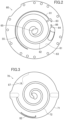
- FIG. 2 is a diagram illustrating a bottom view of a configuration of a fixed scroll.
- FIG. 3 is a diagram illustrating a top view of a configuration of a movable scroll.
- FIG. 4 is a diagram illustrating a longitudinal sectional view of an enlarged main part of the scroll compressor.
- FIG. 5 is a diagram illustrating how oil flows at the beginning of communication between a communication port and a fixed-side oil groove.
- FIG. 6 is a diagram illustrating how oil flows during communication between the communication port and the fixed-side oil groove.
- FIG. 7 is a diagram illustrating how oil flows immediately before the end of the communication between the communication port and the fixed-side oil groove.
- FIG. 8 is a diagram illustrating a state in which an outer oil supply operation and a back pressure adjusting operation are being performed.
- FIG. 9 is a diagram for explaining a period during which the communication port and an oil supply groove communicate with each other.
- a scroll compressor ( 10 ) is placed in a refrigerant circuit of a vapor compression refrigeration cycle.
- a refrigerant compressed in the scroll compressor ( 10 ) condenses in a condenser, has its pressure decreased in a decompression mechanism, evaporates in an evaporator, and is then sucked into the scroll compressor ( 10 ).
- the scroll compressor ( 10 ) includes a casing ( 20 ), and an electric motor ( 30 ) and a compression mechanism ( 40 ) housed in the casing ( 20 ).
- the casing ( 20 ) has a vertically oriented cylindrical shape, and is configured as a closed dome.
- the electric motor ( 30 ) includes a stator ( 31 ) fixed to the casing ( 20 ) and a rotor ( 32 ) inside the stator ( 31 ).
- the rotor ( 32 ) is fixed to a drive shaft ( 11 ).
- the casing ( 20 ) has, at its bottom, an oil reservoir ( 21 ) for storing oil.
- a suction pipe ( 12 ) is connected to an upper portion of the casing ( 20 ).
- a discharge pipe ( 13 ) is connected to a barrel of the casing ( 20 ).
- a housing ( 50 ) is fixed to the casing ( 20 ).
- the housing ( 50 ) is located above the electric motor ( 30 ).
- the compression mechanism ( 40 ) is located above the housing ( 50 ).
- the discharge pipe ( 13 ) has an inflow end between the electric motor ( 30 ) and the housing ( 50 ).
- the drive shaft ( 11 ) extends vertically along the center axis of the casing ( 20 ).
- the drive shaft ( 11 ) includes a main shaft portion ( 14 ) and an eccentric portion ( 15 ) provided at the upper end of the main shaft portion ( 14 ).
- the main shaft portion ( 14 ) has a lower portion rotatably supported by a lower bearing ( 22 ).
- the lower bearing ( 22 ) is fixed to the inner circumferential surface of the casing ( 20 ).
- the main shaft portion ( 14 ) has an upper portion extending so as to pass through the housing ( 50 ) and rotatably supported by an upper bearing ( 51 ) of the housing ( 50 ).
- the compression mechanism ( 40 ) includes a fixed scroll ( 60 ) and a movable scroll ( 70 ).
- the fixed scroll ( 60 ) is fixed to the upper surface of the housing ( 50 ).
- the movable scroll ( 70 ) is interposed between the fixed scroll ( 60 ) and the housing ( 50 ).
- the housing ( 50 ) includes an annular portion ( 52 ) and a recess ( 53 ).
- the annular portion ( 52 ) forms the outer circumference of the housing ( 50 ).
- the recess ( 53 ) is provided in a central upper portion of the housing ( 50 ).
- the upper bearing ( 51 ) is located below the recess ( 53 ).
- the housing ( 50 ) is fixed to the inside of the casing ( 20 ).
- the inner circumferential surface of the casing ( 20 ) and the outer circumferential surface of the annular portion ( 52 ) of the housing ( 50 ) are in airtight contact with each other throughout the entire circumference.
- the housing ( 50 ) partitions the interior of the casing ( 20 ) into an upper space ( 23 ) in which the compression mechanism ( 40 ) is housed and a lower space ( 24 ) in which the electric motor ( 30 ) is housed.
- the fixed scroll ( 60 ) includes a fixed-side end plate ( 61 ), an outer circumferential wall ( 63 ) in a substantially cylindrical shape which stands on the outer edge of the lower surface of the fixed-side end plate ( 61 ), and a spiral fixed-side wrap ( 62 ) which stands inside the outer circumferential wall ( 63 ) of the fixed-side end plate ( 61 ) (see FIG. 2 ).
- the fixed-side end plate ( 61 ) is located on the outer circumference and continuous with the fixed-side wrap ( 62 ).
- the end surface of the fixed-side wrap ( 62 ) and the end surface of the outer circumferential wall ( 63 ) are substantially flush with each other.
- the fixed scroll ( 60 ) is fixed to the housing ( 50 ).
- the movable scroll ( 70 ) includes a movable-side end plate ( 71 ), a spiral movable-side wrap ( 72 ) located on the upper surface of the movable-side end plate ( 71 ), and a boss ( 73 ) located at a central portion of the lower surface of the movable-side end plate ( 71 ) (see FIG. 3 ).
- the eccentric portion ( 15 ) of the drive shaft ( 11 ) is inserted into the boss ( 73 ), whereby the boss ( 73 ) is connected to the drive shaft ( 11 ).
- An annular recess is formed in a portion of the upper portion of the housing ( 50 ) radially outside the recess ( 53 ).
- a back pressure chamber ( 54 ) is defined by the annular recess in the upper portion of the housing ( 50 ), the fixed scroll ( 60 ), and the movable scroll ( 70 ).
- An intermediate-pressure refrigerant is supplied from a compression chamber (S) in the course of compression to the back pressure chamber ( 54 ).
- the back pressure chamber ( 54 ) has an atmosphere with an intermediate pressure between the suction pressure and discharge pressure of the compression chamber (S).
- the intermediate pressure of the back pressure chamber ( 54 ) acts on the back surface of the movable scroll ( 70 ).
- An Oldham coupling ( 46 ) is provided in the back pressure chamber ( 54 ). The Oldham coupling ( 46 ) blocks the rotation of the movable scroll ( 70 ) on its axis.
- the compression mechanism ( 40 ) includes, between the fixed scroll ( 60 ) and the movable scroll ( 70 ), the compression chamber (S) into which a refrigerant flows.
- the movable scroll ( 70 ) is placed so that the movable-side wrap ( 72 ) meshes with the fixed-side wrap ( 62 ) of the fixed scroll ( 60 ).
- the lower surface of the outer circumferential wall ( 63 ) of the fixed scroll ( 60 ) serves as a sliding surface that faces the movable scroll ( 70 ).
- the upper surface of the movable-side end plate ( 71 ) of the movable scroll ( 70 ) serves as a sliding surface that faces the fixed scroll ( 60 ).
- a suction port ( 64 ) that communicates with the compression chamber (S) is formed in the outer circumferential wall ( 63 ) of the fixed scroll ( 60 ).
- the suction pipe ( 12 ) is connected to the upstream side of the suction port ( 64 ).
- the compression chamber (S) is partitioned into an outer chamber (S 1 ) located radially outward of the movable scroll ( 70 ) and inner chambers (S 2 ) located radially inward of the movable scroll ( 70 ).
- the outer chamber (S 1 ) and the inner chambers (S 2 ) become separate sections with the contact portion serving as a boundary (see, e.g., FIG. 5 ).
- the fixed-side end plate ( 61 ) of the fixed scroll ( 60 ) has, at its center, an outlet ( 65 ).
- the high-pressure refrigerant compressed by the compression mechanism ( 40 ) flows out of the compression mechanism ( 40 ) to the lower space ( 24 ) via a path (not shown) formed through the fixed-side end plate ( 61 ) of the fixed scroll ( 60 ) and the housing ( 50 ).
- An oil supply hole ( 16 ) is provided inside the drive shaft ( 11 ) so as to extend vertically from the lower end to the upper end of the drive shaft ( 11 ). A lower end portion of the drive shaft ( 11 ) is immersed in the oil reservoir ( 21 ). The oil supply hole ( 16 ) supplies the oil in the oil reservoir ( 21 ) to the lower bearing ( 22 ) and the upper bearing ( 51 ), and to the gap between the boss ( 73 ) and the drive shaft ( 11 ). The oil supply hole ( 16 ) is open to the upper end surface of the drive shaft ( 11 ) and supplies oil to above the drive shaft ( 11 ).
- the recess ( 53 ) of the housing ( 50 ) communicates with the oil supply hole ( 16 ) of the drive shaft ( 11 ) via the inside of the boss ( 73 ) of the movable scroll ( 70 ).
- the high-pressure oil is supplied to the recess ( 53 ), so that a high pressure equivalent to the discharge pressure of the compression mechanism ( 40 ) acts on the recess ( 53 ).
- the movable scroll ( 70 ) is pressed onto the fixed scroll ( 60 ) by the high pressure that acts on the recess ( 53 ).
- An oil path ( 55 ) is provided in the housing ( 50 ) and the fixed scroll ( 60 ).
- the oil path ( 55 ) has an inflow end that communicates with the recess ( 53 ) of the housing ( 50 ) (not shown).
- the oil path ( 55 ) has an outflow end open to the sliding surface of the fixed scroll ( 60 ).
- the high-pressure oil in the recess ( 53 ) is supplied to the sliding surfaces of the movable-side end plate ( 71 ) of the movable scroll ( 70 ) and the outer circumferential wall ( 63 ) of the fixed scroll ( 60 ).
- the sliding surface of the outer circumferential wall ( 63 ) of the fixed scroll ( 60 ) has a fixed-side oil groove ( 81 ) serving as an outer oil supply mechanism ( 80 ), an oil supply groove ( 86 )(an oil supply portion) serving as an inner oil supply mechanism ( 85 ), and an intermediate-pressure groove ( 83 ) (an intermediate-pressure portion).
- the fixed-side oil groove ( 81 ) is formed in the sliding surface, of the outer circumferential wall ( 63 ) of the fixed scroll ( 60 ), which faces the movable-side end plate ( 71 ) of the movable scroll ( 70 ).
- the fixed-side oil groove ( 81 ) extends substantially in an arc shape along the inner circumferential surface of the outer circumferential wall ( 63 ) of the fixed scroll ( 60 ).
- the oil path ( 55 ) communicates with the fixed-side oil groove ( 81 ), and oil is supplied to the fixed-side oil groove ( 81 ) from the oil path ( 55 ).
- the oil supply groove ( 86 ) extends along the circumferential direction of the fixed scroll ( 60 ).
- the oil supply groove ( 86 ) has one end that communicates with the suction port ( 64 ). Note that the oil supply groove ( 86 ) merely needs to communicate with a suction region of the compression chamber (S) upstream of the suction-side end of the movable-side wrap ( 72 ).
- the intermediate-pressure groove ( 83 ) is formed between the fixed-side oil groove ( 81 ) and the oil supply groove ( 86 ).
- the intermediate-pressure groove ( 83 ) has one end that communicates with the compression chamber (S) in the course of compression (under intermediate pressure).
- the sliding surface of the movable-side end plate ( 71 ) of the movable scroll ( 70 ) has a movable-side oil groove ( 82 ) serving as the outer oil supply mechanism ( 80 ), and a communication port ( 87 ) serving as the inner oil supply mechanism ( 85 ).
- the movable-side oil groove ( 82 ) is formed near an end portion of the fixed-side oil groove ( 81 ) of the fixed scroll ( 60 ).
- the movable-side oil groove ( 82 ) is substantially arc-shaped.
- An end portion of the movable-side oil groove ( 82 ) closer to the fixed-side oil groove ( 81 ) is bent and extends toward the center of the movable scroll ( 70 ).
- the movable-side oil groove ( 82 ) communicates with the fixed-side oil groove ( 81 ) and the outer chamber (S 1 ) of the compression chamber (S) during one rotation of the movable scroll ( 70 ).
- the communication port ( 87 ) passes through an outer peripheral portion of the movable-side end plate ( 71 ) in the thickness direction thereof.
- the communication port ( 87 ) allows the sliding surface of the movable scroll ( 70 ) and the back pressure chamber ( 54 ) to communicate with each other.
- the communication port ( 87 ) of the movable scroll ( 70 ) communicating with the oil supply groove ( 86 ) of the fixed scroll ( 60 ) as indicated by the arrow in FIG. 4 allows oil in the back pressure chamber ( 54 ) to be supplied to the suction port ( 64 ).
- the compression mechanism ( 40 ) performs an inner oil supply operation for supplying oil to the inner chambers (S 2 ), an outer oil supply operation for supplying oil to the outer chambers (S 1 ), and a back pressure adjusting operation for supplying the intermediate-pressure refrigerant to the back pressure chamber ( 54 ). Specifically, the compression mechanism ( 40 ) sequentially repeats the inner oil supply operation, the outer oil supply operation, and the back pressure adjusting operation during one rotation of the movable scroll ( 70 ).
- the electric motor ( 30 ) When activated, the electric motor ( 30 ) rotatably drives the movable scroll ( 70 ) of the compression mechanism ( 40 ). Since the rotation of the movable scroll ( 70 ) is blocked by the Oldham coupling ( 46 ), the movable scroll ( 70 ) performs only the eccentric rotation about the axis of the drive shaft ( 11 ).
- the eccentric rotation of the movable scroll ( 70 ) partitions the compression chamber (S) into the outer chamber (S 1 ) and the inner chambers (S 2 ).
- the plurality of inner chambers (S 2 ) are formed between the fixed-side wrap ( 62 ) of the fixed scroll ( 60 ) and the movable-side wrap ( 72 ) of the movable scroll ( 70 ).
- these inner chambers (S 2 ) gradually come closer to the center (i.e., the outlet ( 65 )) and the volumes of these inner chambers (S 2 ) gradually decrease.
- the refrigerant is gradually compressed in the inner chambers (S 2 ) in this manner.
- the high-pressure gas refrigerant in the inner chamber (S 2 ) is discharged from the outlet ( 65 ).
- the high-pressure gas refrigerant flows out to the lower space ( 24 ) via the path formed in the fixed scroll ( 60 ) and the path formed in the housing ( 50 ).
- the high-pressure gas refrigerant in the lower space ( 24 ) is discharged outside the casing ( 20 ) via the discharge pipe ( 13 ).
- the lower space ( 24 ) becomes a high-pressure atmosphere, and the pressure of the oil in the oil reservoir ( 21 ) increases.
- the high-pressure oil in the oil reservoir ( 21 ) flows upward through the oil supply hole ( 16 ) of the drive shaft ( 11 ) and flows out from the opening at the upper end of the eccentric portion ( 15 ) of the drive shaft ( 11 ) to the inside of the boss ( 73 ) of the movable scroll ( 70 ).
- the oil supplied to the boss ( 73 ) is supplied to the gap between the eccentric portion ( 15 ) of the drive shaft ( 11 ) and the boss ( 73 ). Accordingly, the recess ( 53 ) of the housing ( 50 ) becomes a high-pressure atmosphere equivalent to the discharge pressure of the compression mechanism ( 40 ). The high pressure of the recess ( 53 ) presses the movable scroll ( 70 ) onto the fixed scroll ( 60 ).
- the high-pressure oil accumulated in the recess ( 53 ) flows out through the oil path ( 55 ) to the fixed-side oil groove ( 81 ) (not shown). Accordingly, the oil with the high pressure equivalent to the discharge pressure of the compression mechanism ( 40 ) is supplied to the fixed-side oil groove ( 81 ).
- An intermediate-pressure refrigerant is intermittently supplied from the compression chamber (S) under intermediate pressure to the back pressure chamber ( 54 ).
- the back pressure chamber ( 54 ) has an atmosphere with a predetermined intermediate pressure.
- the inner oil supply operation, the outer oil supply operation, and the back pressure adjusting operation are sequentially performed as the movable scroll ( 70 ) rotates eccentrically in this state.
- the oil in the fixed-side oil groove ( 81 ) is used to lubricate the sliding surfaces around the fixed-side oil groove ( 81 ).
- the inner oil supply operation is performed when the movable scroll ( 70 ) reaches the eccentric angular position illustrated in, for example, FIG. 5 .
- the communication port ( 87 ) and the oil supply groove ( 86 ) communicate with each other, and the oil in the back pressure chamber ( 54 ) is supplied to the oil supply groove ( 86 ).
- the oil supplied to the oil supply groove ( 86 ) is supplied to the suction port ( 64 ) of the compression chamber (S).
- the period during which the communication port ( 87 ) and the oil supply groove ( 86 ) communicate with each other is set as appropriate.
- the communication port ( 87 ) and the oil supply groove ( 86 ) are determined to communicate with each other within a predetermined period in which the center position (C 2 ) of a suction-side end of the movable-side wrap ( 72 ) in the thickness direction is located radially outward of the center position (C 1 ) of the space between adjacent turns of the fixed-side wrap ( 62 ).
- the communication port ( 87 ) and the oil supply groove ( 86 ) start communicating with each other when the suction of the refrigerant is completely blocked by the movable scroll ( 70 ).
- the period in which the communication port ( 87 ) and the oil supply groove ( 86 ) communicate with each other is determined by setting the position of the communication port ( 87 ) and the width of the oil supply groove ( 86 ) as appropriate.
- the oil in the back pressure chamber ( 54 ) flows through the communication port ( 87 ), the oil supply groove ( 86 ), and the suction port ( 64 ) toward the inner chambers (S 2 ) as indicated by the arrows in FIG. 5 .
- This can improve the oil sealing performances of the inner chambers (S 2 ).
- the entire communication port ( 87 ) is located within the oil supply groove ( 86 ).
- the center position (C 2 ) of the movable-side wrap ( 72 ) is located radially outward of the center position (C 1 ) of the space between adjacent turns of the fixed-side wrap ( 62 ). This facilitates supplying oil to the inner chambers (S 2 ) (see the arrows in FIG. 6 ).
- the outer oil supply operation is performed when the movable scroll ( 70 ) in the eccentric angular position illustrated in FIG. 7 further rotates eccentrically, for example, to the eccentric angular position illustrated in FIG. 8 .
- the fixed-side oil groove ( 81 ) and the movable-side oil groove ( 82 ) communicate with each other, and the oil in the fixed-side oil groove ( 81 ) is delivered to the movable-side oil groove ( 82 ). Since a portion of the movable-side oil groove ( 82 ) bent radially inward communicates with the outer chamber (S 1 ) at this moment, the oil in the movable-side oil groove ( 82 ) is supplied to the outer chamber (S 1 ). This can improve the oil sealing performances of the outer chamber (S 1 ).
- the back pressure adjusting operation is also performed.
- the communication port ( 87 ) and the intermediate-pressure groove ( 83 ) communicate with each other.
- the refrigerant in the outer chamber (S 1 ) under intermediate pressure is supplied through the intermediate-pressure groove ( 83 ) and the communication port ( 87 ) to the back pressure chamber ( 54 ).
- the back pressure chamber ( 54 ) has an atmosphere with a predetermined intermediate pressure.
- the inner oil supply operation is performed again. Thereafter, the outer oil supply operation and the back pressure adjusting operation are sequentially repeated.
- the period in which the communication port ( 87 ) and the oil supply groove ( 86 ) communicate with each other is set with reference to an angle at which the suction of the refrigerant into the outer chamber (S 1 ) is completely blocked.
- the communication port ( 87 ) communicates with the oil supply groove ( 86 ) within a predetermined period in which the movable scroll ( 70 ) rotates in a range of from 0° to 100°, where 0° is the angle at which the suction into the outer chamber (S 1 ) is completely blocked.
- the predetermined period as used herein is represented by the rotational angle ⁇ of the movable scroll ( 70 ), and is determined by the position of the communication port ( 87 ) and the width of the oil supply groove ( 86 ).
- oil can be supplied to the inner chamber (S 2 ) of the compression chamber (S) at predetermined timing.
- the scroll compressor ( 10 ) of this embodiment includes the fixed scroll ( 60 ), and the movable scroll ( 70 ) that forms the compression chamber (S) with the fixed scroll ( 60 ).
- This scroll compressor ( 10 ) includes: a back pressure chamber ( 54 ) allowing an intermediate pressure between a suction pressure and a discharge pressure of the compression chamber (S) to act on a surface of the movable scroll ( 70 ) opposite to a sliding surface of the movable scroll ( 70 ); an outer oil supply mechanism ( 80 ) configured to supply oil to an outer chamber (S 1 ) of the compression chamber (S) located radially outward of a movable-side wrap ( 72 ) of the movable scroll ( 70 ); and an inner oil supply mechanism ( 85 ) configured to supply oil to an inner chamber (S 2 ) of the compression chamber (S) located radially inward of the movable-side wrap ( 72 ) of the movable scroll ( 70 ), wherein the inner oil supply mechanism ( 85 ) includes an oil supply groove ( 86
- the outer oil supply mechanism ( 80 ) configured to supply oil to the outer chamber (S 1 ) of the compression chamber (S) and the inner oil supply mechanism ( 85 ) configured to supply oil to the inner chambers (S 2 ) are provided.
- the inner oil supply mechanism ( 85 ) has the oil supply groove ( 86 ) and the communication port ( 87 ).
- the communication port ( 87 ) and the oil supply groove ( 86 ) communicate with each other within the predetermined period in which the center position (C 2 ) of the suction-side end of the wrap ( 72 ) of the movable scroll ( 70 ) in the thickness direction is located radially outward of the center position (C 1 ) of the space between adjacent turns of the wrap of the fixed scroll ( 60 ).
- oil can be supplied to the spaces in the compression chamber (S) which are located radially inward and outward of the movable scroll ( 70 ).
- the scroll compressor ( 10 ) of this embodiment has the intermediate-pressure groove ( 83 ) (intermediate-pressure portion) formed in the sliding surface of the movable scroll ( 70 ) to communicate with the compression chamber (S) in the course of compression.
- the communication port ( 87 ) communicates alternately with the oil supply groove ( 86 ) and the intermediate-pressure groove ( 83 ) during one rotation of the movable scroll ( 70 ).
- the communication port ( 87 ) communicates with the oil supply groove ( 86 ) and the intermediate-pressure groove ( 83 ) alternately during one rotation of the movable scroll ( 70 ).
- an intermediate-pressure refrigerant is intermittently supplied from the compression chamber (S) under intermediate pressure to the back pressure chamber ( 54 ).
- the scroll compressor ( 10 ) of this embodiment is configured such that the communication port ( 87 ) communicates with the oil supply groove ( 86 ) within the predetermined period in which the movable scroll ( 70 ) rotates in the range of from 0° to 100°, where 0° is the angle at which the suction into the outer chamber (S 1 ) is completely blocked.
- the period in which the communication port ( 87 ) and the oil supply groove ( 86 ) communicate with each other is set with reference to the angle at which the suction into the outer chamber (S 1 ) is completely blocked.
- oil can be supplied to the inner chamber (S 2 ) of the compression chamber (S) at predetermined timing.
- the present disclosure is useful for a scroll compressor.
Applications Claiming Priority (3)
| Application Number | Priority Date | Filing Date | Title |
|---|---|---|---|
| JP2019-167368 | 2019-09-13 | ||
| JP2019167368A JP2021042749A (ja) | 2019-09-13 | 2019-09-13 | スクロール圧縮機 |
| PCT/JP2020/031324 WO2021049267A1 (ja) | 2019-09-13 | 2020-08-19 | スクロール圧縮機 |
Related Parent Applications (1)
| Application Number | Title | Priority Date | Filing Date |
|---|---|---|---|
| PCT/JP2020/031324 Continuation WO2021049267A1 (ja) | 2019-09-13 | 2020-08-19 | スクロール圧縮機 |
Publications (2)
| Publication Number | Publication Date |
|---|---|
| US20220178373A1 US20220178373A1 (en) | 2022-06-09 |
| US11859617B2 true US11859617B2 (en) | 2024-01-02 |
Family
ID=74863996
Family Applications (1)
| Application Number | Title | Priority Date | Filing Date |
|---|---|---|---|
| US17/681,506 Active 2041-01-28 US11859617B2 (en) | 2019-09-13 | 2022-02-25 | Scroll compressor |
Country Status (5)
| Country | Link |
|---|---|
| US (1) | US11859617B2 (ja) |
| EP (1) | EP3992460B1 (ja) |
| JP (1) | JP2021042749A (ja) |
| CN (1) | CN114207284B (ja) |
| WO (1) | WO2021049267A1 (ja) |
Cited By (1)
| Publication number | Priority date | Publication date | Assignee | Title |
|---|---|---|---|---|
| US20230287886A1 (en) * | 2022-03-08 | 2023-09-14 | Samsung Electronics Co., Ltd. | Scroll compressor |
Citations (10)
| Publication number | Priority date | Publication date | Assignee | Title |
|---|---|---|---|---|
| US20050053508A1 (en) * | 2003-09-10 | 2005-03-10 | Fujitsu General Limited | Scroll compressor |
| US20080267803A1 (en) * | 2007-04-25 | 2008-10-30 | Byung-Kil Yoo | Compressor and oil supplying structure therefor |
| JP2012077616A (ja) | 2010-09-30 | 2012-04-19 | Daikin Industries Ltd | スクロール型圧縮機 |
| CN102454603A (zh) | 2010-10-28 | 2012-05-16 | 日立空调·家用电器株式会社 | 涡旋式压缩机 |
| WO2012127795A1 (ja) | 2011-03-23 | 2012-09-27 | ダイキン工業株式会社 | スクロール型圧縮機 |
| US20130216416A1 (en) * | 2012-02-14 | 2013-08-22 | Hitachi Appliances, Inc. | Scroll Compressor |
| US20150139844A1 (en) * | 2013-06-27 | 2015-05-21 | Emerson Climate Technologies, Inc. | Scroll compressor with oil management system |
| US20150260189A1 (en) * | 2012-09-27 | 2015-09-17 | Daikin Industries, Ltd. | Scroll compressor |
| WO2016136185A1 (ja) | 2015-02-27 | 2016-09-01 | ダイキン工業株式会社 | スクロール型圧縮機 |
| US20180231002A1 (en) * | 2017-02-13 | 2018-08-16 | Lg Electronics Inc. | Scroll compressor |
Family Cites Families (1)
| Publication number | Priority date | Publication date | Assignee | Title |
|---|---|---|---|---|
| JP6503901B2 (ja) * | 2015-06-02 | 2019-04-24 | ダイキン工業株式会社 | スクロール型圧縮機 |
-
2019
- 2019-09-13 JP JP2019167368A patent/JP2021042749A/ja active Pending
-
2020
- 2020-08-19 WO PCT/JP2020/031324 patent/WO2021049267A1/ja unknown
- 2020-08-19 CN CN202080055357.3A patent/CN114207284B/zh active Active
- 2020-08-19 EP EP20862727.3A patent/EP3992460B1/en active Active
-
2022
- 2022-02-25 US US17/681,506 patent/US11859617B2/en active Active
Patent Citations (16)
| Publication number | Priority date | Publication date | Assignee | Title |
|---|---|---|---|---|
| US20050053508A1 (en) * | 2003-09-10 | 2005-03-10 | Fujitsu General Limited | Scroll compressor |
| US20080267803A1 (en) * | 2007-04-25 | 2008-10-30 | Byung-Kil Yoo | Compressor and oil supplying structure therefor |
| JP2012077616A (ja) | 2010-09-30 | 2012-04-19 | Daikin Industries Ltd | スクロール型圧縮機 |
| CN102454603A (zh) | 2010-10-28 | 2012-05-16 | 日立空调·家用电器株式会社 | 涡旋式压缩机 |
| JP2012092773A (ja) | 2010-10-28 | 2012-05-17 | Hitachi Appliances Inc | スクロール圧縮機 |
| US20140010694A1 (en) | 2011-03-23 | 2014-01-09 | Yoshitomo Tsuka | Screw compressor |
| CN103429901A (zh) | 2011-03-23 | 2013-12-04 | 大金工业株式会社 | 涡旋式压缩机 |
| WO2012127795A1 (ja) | 2011-03-23 | 2012-09-27 | ダイキン工業株式会社 | スクロール型圧縮機 |
| US20130216416A1 (en) * | 2012-02-14 | 2013-08-22 | Hitachi Appliances, Inc. | Scroll Compressor |
| US9181945B2 (en) * | 2012-02-14 | 2015-11-10 | Hitachi Appliances, Inc. | Scroll compressor with channels intermittently communicating internal and external compression chambers with back pressure chamber |
| US20150260189A1 (en) * | 2012-09-27 | 2015-09-17 | Daikin Industries, Ltd. | Scroll compressor |
| US20150139844A1 (en) * | 2013-06-27 | 2015-05-21 | Emerson Climate Technologies, Inc. | Scroll compressor with oil management system |
| WO2016136185A1 (ja) | 2015-02-27 | 2016-09-01 | ダイキン工業株式会社 | スクロール型圧縮機 |
| CN107208634A (zh) | 2015-02-27 | 2017-09-26 | 大金工业株式会社 | 涡旋式压缩机 |
| US20180051697A1 (en) * | 2015-02-27 | 2018-02-22 | Daikin Industries, Ltd. | Scroll-type compressor |
| US20180231002A1 (en) * | 2017-02-13 | 2018-08-16 | Lg Electronics Inc. | Scroll compressor |
Non-Patent Citations (2)
| Title |
|---|
| International Preliminary Report of corresponding PCT Application No. PCT/JP2020/031324 dated Mar. 24, 2022. |
| International Search Report of corresponding PCT Application No. PCT/JP2020/031324 dated Nov. 2, 2020. |
Cited By (1)
| Publication number | Priority date | Publication date | Assignee | Title |
|---|---|---|---|---|
| US20230287886A1 (en) * | 2022-03-08 | 2023-09-14 | Samsung Electronics Co., Ltd. | Scroll compressor |
Also Published As
| Publication number | Publication date |
|---|---|
| WO2021049267A1 (ja) | 2021-03-18 |
| CN114207284A (zh) | 2022-03-18 |
| EP3992460A1 (en) | 2022-05-04 |
| CN114207284B (zh) | 2023-09-26 |
| EP3992460B1 (en) | 2023-11-15 |
| EP3992460A4 (en) | 2022-10-26 |
| JP2021042749A (ja) | 2021-03-18 |
| US20220178373A1 (en) | 2022-06-09 |
Similar Documents
| Publication | Publication Date | Title |
|---|---|---|
| US11022120B2 (en) | Scroll compressor with first and second compression chambers having first and second discharge start points | |
| JP5954453B1 (ja) | スクロール型圧縮機 | |
| US9163632B2 (en) | Injection port and orbiting-side wrap for a scroll compressor | |
| US20160040667A1 (en) | Scroll compressor | |
| US9243637B2 (en) | Scroll compressor reducing over-compression loss | |
| EP3933202A1 (en) | Scroll compressor | |
| US11859617B2 (en) | Scroll compressor | |
| JP6688972B2 (ja) | スクロール圧縮機 | |
| JP2010007550A (ja) | スクロール型流体機械 | |
| JP2006177225A (ja) | ロータリ圧縮機 | |
| JP2016223390A (ja) | スクロール型圧縮機 | |
| JP6709971B2 (ja) | スクロール圧縮機 | |
| US20180298900A1 (en) | Compressor | |
| WO2019187272A1 (ja) | ロータリコンプレッサ | |
| JP6008516B2 (ja) | スクロール圧縮機 | |
| EP3992461A1 (en) | Scroll compressor | |
| US11067078B2 (en) | Scroll compressor having single discharge port open at starting end of fixed-side wrap | |
| JP2004076652A (ja) | スクロール型流体機械 | |
| JP2006194193A (ja) | スクロール式流体機械 | |
| JP2007046492A (ja) | スクロール圧縮機 | |
| JP2017031943A (ja) | スクロール圧縮機 | |
| JPH0826863B2 (ja) | スクロール圧縮機 |
Legal Events
| Date | Code | Title | Description |
|---|---|---|---|
| AS | Assignment |
Owner name: DAIKIN INDUSTRIES, LTD., JAPAN Free format text: ASSIGNMENT OF ASSIGNORS INTEREST;ASSIGNOR:TSUKA, YOSHITOMO;REEL/FRAME:059107/0713 Effective date: 20211015 |
|
| FEPP | Fee payment procedure |
Free format text: ENTITY STATUS SET TO UNDISCOUNTED (ORIGINAL EVENT CODE: BIG.); ENTITY STATUS OF PATENT OWNER: LARGE ENTITY |
|
| STPP | Information on status: patent application and granting procedure in general |
Free format text: DOCKETED NEW CASE - READY FOR EXAMINATION |
|
| STPP | Information on status: patent application and granting procedure in general |
Free format text: NOTICE OF ALLOWANCE MAILED -- APPLICATION RECEIVED IN OFFICE OF PUBLICATIONS |
|
| STPP | Information on status: patent application and granting procedure in general |
Free format text: PUBLICATIONS -- ISSUE FEE PAYMENT RECEIVED |
|
| STPP | Information on status: patent application and granting procedure in general |
Free format text: PUBLICATIONS -- ISSUE FEE PAYMENT VERIFIED |
|
| STCF | Information on status: patent grant |
Free format text: PATENTED CASE |