US11650401B2 - Zoom lens and imaging apparatus - Google Patents
Zoom lens and imaging apparatus Download PDFInfo
- Publication number
- US11650401B2 US11650401B2 US17/024,941 US202017024941A US11650401B2 US 11650401 B2 US11650401 B2 US 11650401B2 US 202017024941 A US202017024941 A US 202017024941A US 11650401 B2 US11650401 B2 US 11650401B2
- Authority
- US
- United States
- Prior art keywords
- lens group
- lens
- denoted
- zoom
- conditional expression
- Prior art date
- Legal status (The legal status is an assumption and is not a legal conclusion. Google has not performed a legal analysis and makes no representation as to the accuracy of the status listed.)
- Active, expires
Links
Images


Classifications
-
- G—PHYSICS
- G02—OPTICS
- G02B—OPTICAL ELEMENTS, SYSTEMS OR APPARATUS
- G02B15/00—Optical objectives with means for varying the magnification
- G02B15/14—Optical objectives with means for varying the magnification by axial movement of one or more lenses or groups of lenses relative to the image plane for continuously varying the equivalent focal length of the objective
- G02B15/145—Optical objectives with means for varying the magnification by axial movement of one or more lenses or groups of lenses relative to the image plane for continuously varying the equivalent focal length of the objective having five groups only
- G02B15/1451—Optical objectives with means for varying the magnification by axial movement of one or more lenses or groups of lenses relative to the image plane for continuously varying the equivalent focal length of the objective having five groups only the first group being positive
- G02B15/145129—Optical objectives with means for varying the magnification by axial movement of one or more lenses or groups of lenses relative to the image plane for continuously varying the equivalent focal length of the objective having five groups only the first group being positive arranged +-+++
-
- G—PHYSICS
- G02—OPTICS
- G02B—OPTICAL ELEMENTS, SYSTEMS OR APPARATUS
- G02B15/00—Optical objectives with means for varying the magnification
- G02B15/14—Optical objectives with means for varying the magnification by axial movement of one or more lenses or groups of lenses relative to the image plane for continuously varying the equivalent focal length of the objective
- G02B15/16—Optical objectives with means for varying the magnification by axial movement of one or more lenses or groups of lenses relative to the image plane for continuously varying the equivalent focal length of the objective with interdependent non-linearly related movements between one lens or lens group, and another lens or lens group
- G02B15/163—Optical objectives with means for varying the magnification by axial movement of one or more lenses or groups of lenses relative to the image plane for continuously varying the equivalent focal length of the objective with interdependent non-linearly related movements between one lens or lens group, and another lens or lens group having a first movable lens or lens group and a second movable lens or lens group, both in front of a fixed lens or lens group
- G02B15/167—Optical objectives with means for varying the magnification by axial movement of one or more lenses or groups of lenses relative to the image plane for continuously varying the equivalent focal length of the objective with interdependent non-linearly related movements between one lens or lens group, and another lens or lens group having a first movable lens or lens group and a second movable lens or lens group, both in front of a fixed lens or lens group having an additional fixed front lens or group of lenses
-
- G—PHYSICS
- G02—OPTICS
- G02B—OPTICAL ELEMENTS, SYSTEMS OR APPARATUS
- G02B15/00—Optical objectives with means for varying the magnification
- G02B15/14—Optical objectives with means for varying the magnification by axial movement of one or more lenses or groups of lenses relative to the image plane for continuously varying the equivalent focal length of the objective
- G02B15/16—Optical objectives with means for varying the magnification by axial movement of one or more lenses or groups of lenses relative to the image plane for continuously varying the equivalent focal length of the objective with interdependent non-linearly related movements between one lens or lens group, and another lens or lens group
- G02B15/20—Optical objectives with means for varying the magnification by axial movement of one or more lenses or groups of lenses relative to the image plane for continuously varying the equivalent focal length of the objective with interdependent non-linearly related movements between one lens or lens group, and another lens or lens group having an additional movable lens or lens group for varying the objective focal length
Definitions
- the technology of the present disclosure relates to a zoom lens and an imaging apparatus.
- a zoom lens consisting of a plurality of lens groups of which mutual intervals are changed during zooming has been suggested as a lens system usable in a broadcasting camera, a movie imaging camera, a digital camera, and the like.
- JP2017-215406A discloses a zoom lens composed of, in order from an object side to an image side, a first lens group that has a positive refractive power and is not moved for zooming, a second lens group that has a negative refractive power and is moved to the image side during zooming, a lens group that is moved during zooming, an aperture stop, and a lens group that is not moved for zooming.
- JP2016-151732A discloses a zoom lens consisting of, in order from an object side to an image side, a first lens group that has a positive refractive power and is not moved for zooming and is moved during focusing, a second lens group that has a negative refractive power and is moved during zooming, a third lens group that has a positive refractive power and is moved during zooming, a fourth lens group that has a positive refractive power and is moved during zooming, and a fifth lens group that has a positive refractive power.
- JP2016-012118A discloses a zoom lens substantially consisting of, in order from an object side to an image side, a first lens group having a positive refractive power, a second lens group having a negative refractive power, a third lens group having a positive refractive power, a fourth lens group having a positive refractive power, and a fifth lens group having a positive refractive power, in which during zooming, the first lens group and the fifth lens group are fixed, and the second lens group, the third lens group, and the fourth lens group are moved by changing intervals therebetween.
- JP2014-142451A discloses a zoom lens including, in order from an object side to an image side, a first lens group that has a positive refractive power and a focusing function and is not moved for zooming, a second lens group that has a negative refractive power and is monotonically moved to the image side during zooming, a third lens group that has a positive refractive power and is non-linearly moved to the image side during zooming, a fourth lens group that has a positive refractive power and is non-linearly moved to the object side for correcting a change in image surface accompanied by zooming, and a fifth lens group that has a positive refractive power and is not moved for zooming.
- An object of one embodiment according to the technology of the present disclosure is to provide a zoom lens that can achieve a wide angle and a high magnification and has favorable optical characteristics while achieving size reduction, and an imaging apparatus comprising the zoom lens.
- a zoom lens according to one aspect of the technology of the present disclosure comprises, in order from an object side to an image side, only five lens groups consisting of a first lens group having a positive refractive power, a second lens group having a negative refractive power, a third lens group having a positive refractive power, a fourth lens group having a positive refractive power, and a fifth lens group having a positive refractive power as lens groups, in which during zooming, the first lens group and the fifth lens group are fixed with respect to an image surface, and the second lens group, the third lens group, and the fourth lens group are moved along an optical axis by changing intervals with an adjacent lens group, the second lens group includes a negative lens closest to the object side, and in a case where a focal length of the second lens group is denoted by f2, and a focal length of the negative lens of the second lens group closest to the object side is denoted by f21, Conditional Expression (1) below is satisfied.
- the zoom lens of the aspect further satisfies Conditional Expression (1-1) below. 0.68 ⁇ f 2/ f 21 ⁇ 0.8 (1-1)
- the second lens group includes at least one positive lens, and in a case where a maximum value of a d line-based Abbe number of all positive lenses included in the second lens group is denoted by ⁇ 2p, it is preferable to satisfy Conditional Expression (2) below, and it is more preferable to satisfy Conditional Expression (2-1) below. 70 ⁇ 2 p ⁇ 110 (2) 80 ⁇ 2 p ⁇ 100 (2-1)
- a surface, on the image side, of the negative lens of the second lens group closest to the object side has an aspherical shape that has a refractive power lower than a refractive power in a paraxial region at an intersection between a principal ray of a maximum angle of view at a wide angle end and the surface.
- a third and fourth combined lens group obtained by combining the third lens group and the fourth lens group, and the second lens group pass through a point at which a lateral magnification is a power of ⁇ 1 at the same time, and the fourth lens group is moved to the object side.
- an interval between the third lens group and the fourth lens group is largest on a wide angle side from a zoom position at which the lateral magnification of the third and fourth combined lens group is a power of ⁇ 1.
- D34 max a maximum value of the interval between the third lens group and the fourth lens group on the optical axis
- D34w the interval between the third lens group and the fourth lens group on the optical axis at a wide angle end
- f34w a combined focal length of the third lens group and the fourth lens group at the wide angle end
- a stop is arranged between the fourth lens group and the fifth lens group, and the fifth lens group includes, closest to the object side, a vibration proof lens group that is moved in a direction intersecting with the optical axis during image shake correction.
- the vibration proof lens group consists of a negative lens, a positive lens, and a negative lens in order from the object side to the image side.
- the vibration proof lens group has a negative refractive power
- a focal length of the zoom lens at a wide angle end is denoted by fw
- a focal length of the vibration proof lens group is denoted by exert
- Conditional Expression (7) ⁇ 0.2 ⁇ fw/fois ⁇ 0 (7) ⁇ 0.15 ⁇ fw/fois ⁇ 0.05 (7-1)
- An imaging apparatus comprises the zoom lens of the aspect of the present disclosure.
- Consist of or “consisting of” means that a lens that substantially does not have a refractive power, and optical elements such as a stop, a filter, and a cover glass other than a lens, mechanism parts such as a lens flange, a lens barrel, an imaging element, and a camera shake correction mechanism, and the like may be included besides illustrated constituents.
- a “ ⁇ group having a positive refractive power” means that the entire group has a positive refractive power.
- a “ ⁇ group having a negative refractive power” means that the entire group has a negative refractive power.
- a “lens having a positive refractive power” and a “positive lens” have the same meaning.
- a “lens having a negative refractive power” and a “negative lens” have the same meaning.
- a “ ⁇ lens group” is not limited to a configuration consisting of a plurality of lenses and may be configured to consist of only one lens.
- a compound aspherical lens (a lens in which a spherical lens and a film of an aspherical shape formed on the spherical lens are configured as a single unit and function as one aspherical lens as a whole) is not regarded as a cemented lens and is handled as one lens.
- the sign of a refractive power and a surface shape related to a lens including an aspherical surface are considered in a paraxial region unless otherwise specified.
- the “focal length” used in the conditional expressions is a paraxial focal length.
- the values used in the conditional expressions are values in a case based on d line in a state where the object at infinity is focused.
- “d line”, “C line”, “F line”, and “g line” are bright lines.
- the wavelength of d line is 587.56 nanometers (nm).
- the wavelength of C line is 656.27 nanometers (nm).
- the wavelength of F line is 486.13 nanometers (nm).
- the wavelength of g line is 435.84 nanometers (nm).
- FIG. 1 is a diagram corresponding to a zoom lens of Example 1 of the present disclosure and illustrating a cross-sectional view of a configuration and a movement trajectory of a zoom lens according to one embodiment of the present disclosure.
- FIG. 2 is a cross-sectional view illustrating a configuration of the zoom lens and luminous flux illustrated in FIG. 1 .
- FIG. 3 is a diagram for describing an aspherical shape.
- FIG. 4 is each aberration diagram of the zoom lens of Example 1 of the present disclosure.
- FIG. 5 is a diagram illustrating a cross-sectional view of a configuration and a movement trajectory of a zoom lens of Example 2 of the present disclosure.
- FIG. 6 is each aberration diagram of the zoom lens of Example 2 of the present disclosure.
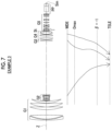
- FIG. 7 is a diagram illustrating a cross-sectional view of a configuration and a movement trajectory of a zoom lens of Example 3 of the present disclosure.
- FIG. 8 is each aberration diagram of the zoom lens of Example 3 of the present disclosure.
- FIG. 9 is a schematic configuration diagram of an imaging apparatus according to one embodiment of the present disclosure.
- FIG. 1 is a diagram illustrating a cross-sectional view of a configuration and a movement trajectory at a wide angle end of a zoom lens according to one embodiment of the present disclosure.
- FIG. 2 is a cross-sectional view illustrating the configuration of the zoom lens and luminous flux. Examples illustrated in FIG. 1 and FIG. 2 correspond to a zoom lens of Example 1 described later.
- a state where an object at infinity is focused is illustrated in the cross-sectional views of FIG. 1 and FIG. 2 .
- a left side is an object side
- a right side is an image side.
- a wide angle end state is illustrated in the uppermost part denoted by “WIDE”
- a first middle focal length state is illustrated in the second part denoted by “MIDDLE1” from top
- a second middle focal length state is illustrated in the third part denoted by “MIDDLE2” from top
- the telephoto end state is illustrated in a lowermost part denoted by “TELE”.
- axial luminous flux wa and luminous flux wb of the maximum angle of view in the wide angle end state axial luminous flux m 1 a and luminous flux m 1 b of the maximum angle of view in the first middle focal length state
- axial luminous flux m 2 a and luminous flux m 2 b of the maximum angle of view in the second middle focal length state axial luminous flux to and luminous flux tb of the maximum angle of view in the telephoto end state
- FIG. 1 and FIG. 2 an example in which an optical member PP in which an incidence surface and an emission surface are parallel is arranged between the zoom lens and an image surface Sim is illustrated by assuming application of the zoom lens to an imaging apparatus.
- the optical member PP is a member that is assumed to correspond to various filters, a cover glass, a prism, and the like.
- the various filters include a low-pass filter, an infrared cut filter, and a filter cutting a specific wavelength range.
- the optical member PP is a member not having a refractive power, and the optical member PP can be configured not to be included.
- the zoom lens according to one embodiment of the present disclosure will be described mainly with reference to FIG. 1 .
- the zoom lens comprises only five lens groups consisting of a first lens group G 1 having a positive refractive power, a second lens group G 2 having a negative refractive power, a third lens group G 3 having a positive refractive power, a fourth lens group G 4 having a positive refractive power, and a fifth lens group G 5 having a positive refractive power as lens groups in order from the object side to the image side along an optical axis Z.
- the first lens group G 1 and the fifth lens group G 5 are fixed with respect to the image surface Sim, and the second lens group G 2 , the third lens group G 3 , and the fourth lens group G 4 are moved along the optical axis Z by changing intervals with an adjacent lens group.
- both a high magnification and reduction of a total length are easily achieved while a change in aberration during zooming is suppressed.
- lens groups having a positive refractive power as the third lens group G 3 and the fourth lens group G 4 , axial chromatic aberration on a telephoto side on which the axial chromatic aberration is likely to be increased can be suppressed.
- an advantage of a high magnification is achieved.
- the distance from a lens surface closest to the object side to a lens surface closest to the image side is not changed during zooming, and a change in centroid of a lens system can be reduced.
- convenience of use during imaging can be increased.
- FIG. 1 the movement trajectory of each lens group during zooming from the wide angle end to the telephoto end is schematically illustrated by a solid arrow below each of the second lens group G 2 , the third lens group G 3 , and the fourth lens group G 4 .
- the wide angle end and the telephoto end corresponding to the starting point and the ending point of the movement trajectory, respectively, are denoted by “WIDE” and “TELE”, respectively.
- Each lens group in the example in FIG. 1 is composed of lenses described below. That is, the first lens group G 1 consists of five lenses of lenses L 11 to L 15 in order from the object side to the image side.
- the second lens group G 2 consists of seven lenses of the lenses L 21 to L 27 in order from the object side to the image side.
- the third lens group G 3 consists of one lens of a lens L 31 .
- the fourth lens group G 4 consists of four lenses of lenses L 41 to L 44 in order from the object side to the image side.
- the fifth lens group G 5 consists of 13 lenses of lenses L 51 to L 63 in order from the object side to the image side.
- an aperture stop St is arranged between the fourth lens group G 4 and the fifth lens group G 5 .
- the aperture stop St in FIG. 1 does not illustrate a shape and illustrates a position in an optical axis direction.
- the second lens group G 2 is configured to comprise a negative lens closest to the object side.
- a negative refractive power on the object side inside the second lens group G 2 , the position of an incidence pupil can be brought closer to the object side in the case of a high magnification.
- an increase in diameter of the lens of the first lens group G 1 closest to the object side can be suppressed. Accordingly, an advantage of achieving a wide angle while achieving size reduction is achieved.
- the zoom lens according to the embodiment of the technology of the present disclosure is advantageous for achieving a wide angle and a high magnification and obtaining favorable optical characteristics while achieving size reduction.
- the negative lens of the second lens group G 2 closest to the object side is an aspherical lens.
- the aspherical lens By arranging the aspherical lens on the side of the second lens group G 2 closest to the object side, the distortion at the wide angle end is easily suppressed.
- the surface, on the image side, of the negative lens of the second lens group G 2 closest to the object side is an aspherical surface and the aspherical surface has a shape having a refractive power lower than a refractive power in a paraxial region at an intersection between a principal ray of the maximum angle of view at the wide angle end and the aspherical surface.
- the magnitude of the refractive power at two different points on the same surface of the aspherical lens consisting of a homogeneous medium can be determined from a magnitude relationship of the absolute value of an approximate radius of curvature at each point.
- the preferred shape of the aspherical surface will be described below with reference to FIG. 3 .
- FIG. 3 a cross-sectional view of an aspherical surface Sa having the above shape is illustrated in FIG. 3 .
- a normal line of a surface at an intersection Pa between a principal ray CR of the maximum angle of view at the wide angle end and the aspherical surface Sa is illustrated by a two-dot chain line, and a point at which the normal line intersects with the optical axis Z is illustrated as a point P 1 .
- of a line segment connecting the intersection Pa to the point P 1 can be regarded as the absolute value of an approximate radius of curvature at the intersection Pa of the aspherical surface Sa.
- the absolute value of the radius of curvature in a paraxial region of the aspherical surface Sa is the absolute value of a so-called paraxial radius of curvature.
- the paraxial radius of curvature of the aspherical surface Sa is the radius of a paraxial spherical surface Sp of the aspherical surface Sa, and the absolute value thereof is illustrated by
- the paraxial spherical surface Sp is a spherical surface of the radius
- the “aspherical surface has a refractive power lower than a refractive power in a paraxial region at an intersection between a principal ray of the maximum angle of view at the wide angle end and the aspherical surface” means that
- the distortion at the wide angle end is easily suppressed.
- a surface interval between the aspherical surface and an adjacent surface can be further decreased.
- the size of the second lens group G 2 can be further reduced. Accordingly, since a zoom stroke (movement range during zooming) can be further increased, an advantage of a high magnification is achieved.
- Conditional Expression (2) In a case where the maximum value of the d line-based Abbe number of all positive lenses included in the second lens group G 2 is denoted by ⁇ 2p, it is preferable to satisfy Conditional Expression (2) below.
- Conditional Expression (2) not to be below the lower limit thereof lateral chromatic aberration of a short wavelength caused by the first lens group G 1 on a positive side at the wide angle end can be effectively corrected by the second lens group G 2 .
- Conditional Expression (2) not to be above the upper limit thereof the refractive index of the positive lenses of the second lens group G 2 of which the d line-based Abbe number is ⁇ 2p is not excessively decreased.
- the absolute value of the radius of curvature of the positive lenses is not excessively decreased.
- Conditional Expression (3) In a case where the lateral magnification of the second lens group G 2 at the telephoto end is denoted by ⁇ 2t and the lateral magnification of the second lens group G 2 at the wide angle end is denoted by ⁇ 2w, it is preferable to satisfy Conditional Expression (3) below.
- Conditional Expression (3) not to be below the lower limit thereof a movement amount of the second lens group G 2 during zooming can be suppressed.
- Conditional Expression (3) not to be above the upper limit thereof the refractive power of the second lens group G 2 is not excessively increased. Thus, a change in spherical aberration during zooming is easily suppressed.
- Conditional Expression (3-1) more favorable characteristics can be achieved. 10 ⁇ 2 t/ ⁇ 2 w ⁇ 25 (3) 15 ⁇ 2 t/ ⁇ 2 w ⁇ 20 (3-1)
- Conditional Expression (4) it is preferable to satisfy Conditional Expression (4) below.
- Conditional Expression (4) not to be below the lower limit thereof the refractive power of the third lens group G 3 is not excessively decreased with respect to the fourth lens group G 4 .
- the diameter of the lenses of the fourth lens group G 4 is easily decreased, and the zoom stroke of the third lens group G 3 is easily secured.
- an advantage of a high magnification is achieved.
- Conditional Expression (4) not to be above the upper limit thereof the refractive power of the third lens group G 3 is not excessively increased with respect to the fourth lens group G 4 .
- a third and fourth combined lens group obtained by combining the third lens group G 3 and the fourth lens group G 4 , and the second lens group G 2 pass through a point at which a lateral magnification is a power of ⁇ 1 at the same time, and the fourth lens group G 4 is moved to the object side.
- a high magnification is easily achieved.
- the zoom lens in a state where the object at infinity is focused, it is preferable to configure that the interval between the third lens group G 3 and the fourth lens group G 4 is largest on the wide angle side from the zoom position at which the lateral magnification of the third and fourth combined lens group is a power of ⁇ 1.
- a zoom position at which the interval between the third lens group G 3 and the fourth lens group G 4 is largest is denoted by “Dmax” in the drawing of the movement trajectory in FIG. 1 and corresponds to the first middle focal length state in FIG. 2 .
- the amount of outer edge rays of non-axial luminous flux is largest on the wide angle side from the zoom position at which the lateral magnification of the combined lens group is a power of ⁇ 1.
- a state where the interval between the third lens group G 3 and the fourth lens group G 4 is largest is a state where the third lens group G 3 is extended to the object side.
- the third lens group G 3 having a positive refractive power can be extended to the object side at or near a zoom position at which the amount of outer edge rays of non-axial luminous flux is largest. Accordingly, since the outer edge rays of the non-axial luminous flux in the first lens group G 1 can be further reduced, an increase in diameter of the first lens group G 1 can be suppressed, and an advantage of size reduction is achieved.
- the interval on the optical axis between the third lens group G 3 and the fourth lens group G 4 at the wide angle end is denoted by D34w.
- a combined focal length of the third lens group G 3 and the fourth lens group G 4 at the wide angle end is denoted by f34w.
- Conditional Expression (6) In a case where the combined lateral magnification of the third lens group G 3 and the fourth lens group G 4 at the telephoto end is denoted by ⁇ 34t and the combined lateral magnification of the third lens group G 3 and the fourth lens group G 4 at the wide angle end is denoted by ⁇ 34w, it is preferable to satisfy Conditional Expression (6) below.
- Conditional Expression (6) not to be below the lower limit thereof the movement amount of each lens group moved during zooming can be suppressed. Thus, both size reduction and a high magnification are easily achieved.
- Conditional Expression (6) not to be above the upper limit thereof the refractive power of each lens group moved during zooming is not excessively increased.
- the zoom lens has a vibration proof function.
- a zoom lens of which the zoom magnification exceeds a power of 100 has a long focal length on the telephoto side.
- vibration exerted on the zoom lens during imaging cannot be ignored.
- a vibration proof lens group that is moved in a direction intersecting with the optical axis Z during image shake correction is comprised in the fifth lens group G 5 closest to the object side.
- the aperture stop St is arranged between the fourth lens group G 4 and the fifth lens group G 5 .
- vibration proof lens group By configuring the vibration proof lens group using the lenses of the fifth lens group G 5 which is a lens group fixed during zooming and is a lens group having a small lens diameter and a small weight, vibration proofing is easily controlled. In addition, by arranging the vibration proof lens group on the side of the fifth lens group G 5 which is closest to the object side and close to the aperture stop St, an advantage of suppressing the spherical aberration is achieved.
- the vibration proof lens group has a negative refractive power and Conditional Expression (7) below is satisfied.
- the focal length of the zoom lens at the wide angle end is denoted by fw
- the focal length of the vibration proof lens group is denoted by exert.
- Conditional Expression (7) not to be below the lower limit thereof By satisfying Conditional Expression (7) not to be below the lower limit thereof, the absolute value of the radius of curvature of lenses of the vibration proof lens group is not excessively decreased. Thus, an advantage of suppressing occurrence of the spherical aberration is achieved.
- the upper limit of Conditional Expression (7) is 0 since the vibration proof lens group has a negative refractive power. Furthermore, it is preferable to satisfy Conditional Expression (7-1) below. By satisfying Conditional Expression (7-1) not to be below the lower limit thereof, an advantage of suppressing occurrence of the spherical aberration is achieved.
- the vibration proof lens group consists of a negative lens, a positive lens, and a negative lens in order from the object side to the image side. In such a case, an advantage of suppressing the spherical aberration during image shake correction is achieved.
- the vibration proof lens group consists of three lenses of the lenses L 51 to L 53 . Upward and downward bidirectional arrows shown below the lenses L 51 to L 53 in FIG. 1 indicate that the lenses L 51 to L 53 are the vibration proof lens group.
- the example illustrated in FIG. 1 is one example and can be subjected to various modifications within the scope of the technology of the present disclosure.
- the number of lenses constituting each lens group can be a number different from the example illustrated in FIG. 1 .
- a zoom lens that can achieve a wide angle and a high magnification and has favorable optical characteristics while achieving size reduction can be implemented.
- the “wide angle” here means that the total angle of view at the wide angle end is greater than or equal to 70 degrees
- the “high magnification” means that the zoom magnification is greater than or equal to a power of 100.
- the zoom lens of Example 1 consists of, in order from the object side to the image side, the first lens group G 1 having a positive refractive power, the second lens group G 2 having a negative refractive power, the third lens group G 3 having a positive refractive power, the fourth lens group G 4 having a positive refractive power, the aperture stop St, and the fifth lens group G 5 having a positive refractive power.
- the first lens group G 1 , the aperture stop St, and the fifth lens group G 5 are fixed with respect to the image surface Sim, and the second lens group G 2 , the third lens group G 3 , and the fourth lens group G 4 are moved along the optical axis Z by changing intervals with an adjacent lens group.
- the first lens group G 1 consists of five lenses.
- the second lens group G 2 consists of seven lenses.
- the third lens group G 3 consists of one lens.
- the fourth lens group G 4 consists of four lenses.
- the fifth lens group G 5 consists of 13 lenses.
- the vibration proof lens group consists of three lenses of the first, second, and third lenses of the fifth lens group G 5 from the object side. Above is the summary of the zoom lens of Example 1.
- Table 1A and Table 1B For the zoom lens of Example 1, fundamental lens data is shown in Table 1A and Table 1B, specifications and variable surface intervals are shown in Table 2, and aspherical coefficients are shown in Table 3.
- the fundamental lens data is separately displayed in two tables of Table 1A and Table 1B in order to avoid one long table.
- Table 1A shows the first lens group G 1 to the fourth lens group G 4
- Table 1B shows the aperture stop St, the fifth lens group G 5 , and the optical member PP.
- Table 1A, Table 1B, and Table 2 show data in a state where the object at infinity is focused.
- the field of Sn shows a surface number in a case where the surface closest to the object side is set as a first surface and the number is increased by one at a time toward the image side.
- the field of R shows the radius of curvature of each surface.
- the field of D shows a surface interval on the optical axis between each surface and a surface adjacent thereto on the image side.
- the field of Nd shows the refractive index of each constituent with respect to d line.
- the field of vd shows the d line-based Abbe number of each constituent.
- the field of ⁇ gF shows the partial dispersion ratio of each constituent between g line and F line.
- Table 1A and Table 1B the sign of the radius of curvature of a surface having a shape of a convex surface toward the object side is positive, and the sign of the radius of curvature of a surface having a shape of a convex surface toward the image side is negative.
- the surface number and a word (St) are written in the field of the surface number of the surface corresponding to the aperture stop St.
- a symbol DD[ ] is used for the variable surface interval during zooming.
- the variable surface interval is shown in the field of D by adding the surface number on the object side of the interval in [ ].
- Table 2 shows a zoom magnification Zr, a focal length f, a back focus Bf converted to a distance in air, an F number FNo., a maximum total angle of view 2 ⁇ , and the variable surface interval during zooming based on d line.
- (°) means that the unit is degree.
- values in the wide angle end state, the first middle focal length state, the second middle focal length state, and the telephoto end state are shown in the fields marked with WIDE, MIDDLE1, MIDDLE2, and TELE, respectively.
- Zd aspherical depth (length of a perpendicular line drawn from a point on the aspherical surface having a height h to a plane that is in contact with an aspherical vertex and is perpendicular to the optical axis)
- h height (distance from the optical axis to the lens surface)
- ⁇ means the total sum related to m.
- FIG. 4 illustrates each aberration diagram of the zoom lens of Example 1 in a state where the object at infinity is focused.
- spherical aberration, astigmatism, distortion, and lateral chromatic aberration are illustrated in FIG. 4 .
- aberration in the wide angle end state is illustrated in the uppermost part denoted by “WIDE”
- aberration in the first middle focal length state is illustrated in the second part denoted by “MIDDLE1” from top
- MIDDLE2 aberration in the second middle focal length state
- aberration in the telephoto end state is illustrated in the lowermost part denoted by “TELE”.
- a solid line, a long broken line, a short broken line, and a one-dot chain line illustrate aberration on d line, C line, F line, and g line, respectively.
- a solid line illustrates aberration on d line in a sagittal direction
- a short broken line illustrates aberration on d line in a tangential direction.
- a solid line illustrates aberration on d line.
- a long broken line, a short broken line, and a one-dot chain line illustrate aberration on C line, F line, and g line, respectively.
- FNo. means the F number.
- ⁇ means a half angle of view.
- FIG. 5 A configuration and a movement trajectory of a zoom lens of Example 2 are illustrated in FIG. 5 .
- the zoom lens of Example 2 has the same configuration as the summary of the zoom lens of Example 1.
- fundamental lens data is shown in Table 4A and Table 4B, specifications and variable surface intervals are shown in Table 5, aspherical coefficients are shown in Table 6, and each aberration diagram is illustrated in FIG. 6 .
- FIG. 7 A configuration and a movement trajectory of a zoom lens of Example 3 are illustrated in FIG. 7 .
- the zoom lens of Example 3 has the same configuration as the summary of the zoom lens of Example 1.
- fundamental lens data is shown in Table 7A and Table 7B, specifications and variable surface intervals are shown in Table 8, aspherical coefficients are shown in Table 9, and each aberration diagram is illustrated in FIG. 8 .
- Table 10 shows corresponding values of Conditional Expressions (1) to (7) of the zoom lenses of Examples 1 to 3.
- Example 1 Example 2
- Example 3 (1) f2/f21 0.74 0.73 0.73 (2) ⁇ 2p 94.94 81.64 95.10 (3) ⁇ 2t/ ⁇ 2w 18.34 18.65 18.66 (4) f4/f3 0.49 0.49 0.49 (5) (D34max ⁇ 0.409 0.407 0.396 D34w)/f34w (6) ⁇ 34t/ ⁇ 34w 6.53 6.69 6.74 (7) fw/fois ⁇ 0.10 ⁇ 0.10 ⁇ 0.10 ⁇ 0.10
- the zoom lenses of Examples 1 to 3 are configured in a small size, the total angle of view at the wide angle end is greater than or equal to 70 degrees, and a wide angle of view is provided.
- the zoom magnification is greater than or equal to a power of 120, and a high magnification is achieved.
- High optical characteristics are implemented by favorably correcting various types of aberration.
- the imaging apparatus for example, in a case where the zoom lens is used in combination with an imaging element in which the diameter of an imaging surface is 11 millimeters (mm), it may be required that the diameter of the lens closest to the object side is less than or equal to 205 millimeters (mm). Examples 1 to 3 can deal with such a requirement.
- FIG. 9 illustrates a schematic configuration diagram of an imaging apparatus 100 using a zoom lens 1 according to the embodiment of the present disclosure as one example of an imaging apparatus according to the embodiment of the present disclosure.
- a broadcasting camera, a movie imaging camera, a video camera, and a monitoring camera can be exemplified as the imaging apparatus 100 .
- the imaging apparatus 100 comprises the zoom lens 1 , a filter 2 arranged on the image side of the zoom lens 1 , and an imaging element 3 arranged on the image side of the filter 2 .
- a plurality of lenses comprised in the zoom lens 1 are schematically illustrated.
- the imaging element 3 converts an optical image formed by the zoom lens 1 into an electric signal and can use, for example, a charge coupled device (CCD) or a complementary metal oxide semiconductor (CMOS).
- CCD charge coupled device
- CMOS complementary metal oxide semiconductor
- the imaging element 3 is arranged such that an imaging surface thereof matches an image surface of the zoom lens 1 .
- the imaging apparatus 100 also comprises a signal processing unit 5 performing calculation processing on an output signal from the imaging element 3 , a display unit 6 displaying an image formed by the signal processing unit 5 , a zooming control unit 7 controlling zooming of the zoom lens 1 , and a focusing control unit 8 controlling focusing of the zoom lens 1 . While only one imaging element 3 is illustrated in FIG. 9 , a so-called three-plate type imaging apparatus including three imaging elements may also be used.
- the technology of the present disclosure has been illustratively described with the embodiment and the examples, the technology of the present disclosure is not limited to the embodiment and the examples and can be subjected to various modifications.
- the radius of curvature, the surface interval, the refractive index, the Abbe number, the aspherical coefficient, and the like of each lens are not limited to the values shown in each example of the numerical values and may have other values.
Landscapes
- Physics & Mathematics (AREA)
- General Physics & Mathematics (AREA)
- Optics & Photonics (AREA)
- Nonlinear Science (AREA)
- Lenses (AREA)
- Adjustment Of Camera Lenses (AREA)
Applications Claiming Priority (3)
| Application Number | Priority Date | Filing Date | Title |
|---|---|---|---|
| JPJP2019-173329 | 2019-09-24 | ||
| JP2019173329A JP7144383B2 (ja) | 2019-09-24 | 2019-09-24 | ズームレンズおよび撮像装置 |
| JP2019-173329 | 2019-09-24 |
Publications (2)
| Publication Number | Publication Date |
|---|---|
| US20210088765A1 US20210088765A1 (en) | 2021-03-25 |
| US11650401B2 true US11650401B2 (en) | 2023-05-16 |
Family
ID=74880789
Family Applications (1)
| Application Number | Title | Priority Date | Filing Date |
|---|---|---|---|
| US17/024,941 Active 2041-06-25 US11650401B2 (en) | 2019-09-24 | 2020-09-18 | Zoom lens and imaging apparatus |
Country Status (2)
| Country | Link |
|---|---|
| US (1) | US11650401B2 (ja) |
| JP (1) | JP7144383B2 (ja) |
Families Citing this family (2)
| Publication number | Priority date | Publication date | Assignee | Title |
|---|---|---|---|---|
| WO2020241107A1 (ja) | 2019-05-24 | 2020-12-03 | 川口潔 | 積載用伸縮機能付加シート、及びこれを備える椅子 |
| CN113917674B (zh) * | 2021-10-28 | 2022-12-30 | 东莞市宇瞳光学科技股份有限公司 | 一种变焦镜头 |
Citations (12)
| Publication number | Priority date | Publication date | Assignee | Title |
|---|---|---|---|---|
| JPH07248449A (ja) | 1994-03-09 | 1995-09-26 | Fuji Photo Optical Co Ltd | ズームレンズ系 |
| WO2014073187A1 (ja) | 2012-11-08 | 2014-05-15 | 富士フイルム株式会社 | ズームレンズおよび撮像装置 |
| WO2014073186A1 (ja) | 2012-11-08 | 2014-05-15 | 富士フイルム株式会社 | ズームレンズおよび撮像装置 |
| US20140204252A1 (en) * | 2013-01-23 | 2014-07-24 | Canon Kabushiki Kaisha | Zoom lens and image pickup apparatus including the same |
| US20150355436A1 (en) | 2014-06-06 | 2015-12-10 | Fujifilm Corporation | Zoom lens and imaging apparatus |
| JP2016151732A (ja) | 2015-02-19 | 2016-08-22 | キヤノン株式会社 | ズームレンズ及びそれを有する撮像装置 |
| US20160259155A1 (en) * | 2015-03-06 | 2016-09-08 | Fujifilm Corporation | Zoom lens and imaging apparatus |
| JP2017215406A (ja) | 2016-05-31 | 2017-12-07 | キヤノン株式会社 | ズームレンズ及びそれを有する撮像装置 |
| JP2019008313A (ja) | 2018-09-13 | 2019-01-17 | キヤノン株式会社 | ズームレンズおよび撮像装置 |
| US20190265448A1 (en) | 2018-02-28 | 2019-08-29 | Canon Kabushiki Kaisha | Zoom lens and image pickup apparatus |
| US20200004000A1 (en) * | 2018-06-29 | 2020-01-02 | Fujifilm Corporation | Zoom lens and imaging apparatus |
| JP2020085935A (ja) | 2018-11-15 | 2020-06-04 | キヤノン株式会社 | ズームレンズ及び撮像装置 |
-
2019
- 2019-09-24 JP JP2019173329A patent/JP7144383B2/ja active Active
-
2020
- 2020-09-18 US US17/024,941 patent/US11650401B2/en active Active
Patent Citations (18)
| Publication number | Priority date | Publication date | Assignee | Title |
|---|---|---|---|---|
| JPH07248449A (ja) | 1994-03-09 | 1995-09-26 | Fuji Photo Optical Co Ltd | ズームレンズ系 |
| US5561560A (en) | 1994-03-09 | 1996-10-01 | Fuji Photo Optical Co., Ltd. | Zoom lens system |
| WO2014073187A1 (ja) | 2012-11-08 | 2014-05-15 | 富士フイルム株式会社 | ズームレンズおよび撮像装置 |
| WO2014073186A1 (ja) | 2012-11-08 | 2014-05-15 | 富士フイルム株式会社 | ズームレンズおよび撮像装置 |
| US20150247996A1 (en) | 2012-11-08 | 2015-09-03 | Fujifilm Corporation | Zoom lens and imaging apparatus |
| US20150309292A1 (en) | 2012-11-08 | 2015-10-29 | Fujifilm Corporation | Zoom lens and imaging apparatus |
| US20140204252A1 (en) * | 2013-01-23 | 2014-07-24 | Canon Kabushiki Kaisha | Zoom lens and image pickup apparatus including the same |
| JP2014142451A (ja) | 2013-01-23 | 2014-08-07 | Canon Inc | ズームレンズ及びそれを有する撮像装置 |
| US20150355436A1 (en) | 2014-06-06 | 2015-12-10 | Fujifilm Corporation | Zoom lens and imaging apparatus |
| JP2016012118A (ja) | 2014-06-06 | 2016-01-21 | 富士フイルム株式会社 | ズームレンズおよび撮像装置 |
| JP2016151732A (ja) | 2015-02-19 | 2016-08-22 | キヤノン株式会社 | ズームレンズ及びそれを有する撮像装置 |
| US20160259155A1 (en) * | 2015-03-06 | 2016-09-08 | Fujifilm Corporation | Zoom lens and imaging apparatus |
| JP2017215406A (ja) | 2016-05-31 | 2017-12-07 | キヤノン株式会社 | ズームレンズ及びそれを有する撮像装置 |
| US20190265448A1 (en) | 2018-02-28 | 2019-08-29 | Canon Kabushiki Kaisha | Zoom lens and image pickup apparatus |
| JP2019148759A (ja) | 2018-02-28 | 2019-09-05 | キヤノン株式会社 | ズームレンズ及び撮像装置 |
| US20200004000A1 (en) * | 2018-06-29 | 2020-01-02 | Fujifilm Corporation | Zoom lens and imaging apparatus |
| JP2019008313A (ja) | 2018-09-13 | 2019-01-17 | キヤノン株式会社 | ズームレンズおよび撮像装置 |
| JP2020085935A (ja) | 2018-11-15 | 2020-06-04 | キヤノン株式会社 | ズームレンズ及び撮像装置 |
Non-Patent Citations (1)
| Title |
|---|
| "Notice of Reasons for Refusal" Office Action issued in JP 2019-173329; mailed by the Japanese Patent Office dated Jul. 5, 2022. |
Also Published As
| Publication number | Publication date |
|---|---|
| US20210088765A1 (en) | 2021-03-25 |
| JP2021051160A (ja) | 2021-04-01 |
| JP7144383B2 (ja) | 2022-09-29 |
Similar Documents
| Publication | Publication Date | Title |
|---|---|---|
| US9952446B2 (en) | Zoom lens and image pickup apparatus including the same | |
| JP6695293B2 (ja) | ズームレンズおよび撮像装置 | |
| US11243384B2 (en) | Zoom lens and image pickup apparatus including the same | |
| US9494776B2 (en) | Zoom lens and imaging apparatus | |
| US9739987B2 (en) | Zoom lens and imaging apparatus | |
| US20200310090A1 (en) | Zoom lens and imaging apparatus | |
| US20190064478A1 (en) | Zoom lens and imaging apparatus | |
| CN108459404B (zh) | 变焦镜头及摄像装置 | |
| US8665528B2 (en) | Zoom lens and image pickup apparatus having the same | |
| US11640049B2 (en) | Zoom lens and imaging apparatus | |
| US20190011682A1 (en) | Zoom lens and image pickup apparatus | |
| US9746667B2 (en) | Zoom lens and imaging apparatus | |
| JP2007272216A (ja) | ズームレンズ系、撮像装置及びカメラ | |
| US11650401B2 (en) | Zoom lens and imaging apparatus | |
| US11740443B2 (en) | Zoom lens and imaging apparatus | |
| US10663699B2 (en) | Zoom lens and imaging apparatus | |
| WO2017130479A1 (ja) | ズームレンズおよび撮像装置 | |
| US11125985B2 (en) | Zoom lens and imaging apparatus | |
| US11933952B2 (en) | Zoom lens and imaging apparatus | |
| US11604339B2 (en) | Zoom lens and imaging apparatus | |
| US11125986B2 (en) | Zoom lens and imaging apparatus | |
| JP4913634B2 (ja) | ズームレンズ系、撮像装置及びカメラ | |
| US9958654B2 (en) | Zoom lens and image pickup apparatus including the same | |
| US11294158B2 (en) | Zoom lens and imaging apparatus | |
| WO2019082641A1 (ja) | ズームレンズ及び撮像装置 |
Legal Events
| Date | Code | Title | Description |
|---|---|---|---|
| AS | Assignment |
Owner name: FUJIFILM CORPORATION, JAPAN Free format text: ASSIGNMENT OF ASSIGNORS INTEREST;ASSIGNOR:IKEDA, SHINKICHI;REEL/FRAME:053813/0186 Effective date: 20200629 |
|
| FEPP | Fee payment procedure |
Free format text: ENTITY STATUS SET TO UNDISCOUNTED (ORIGINAL EVENT CODE: BIG.); ENTITY STATUS OF PATENT OWNER: LARGE ENTITY |
|
| STPP | Information on status: patent application and granting procedure in general |
Free format text: DOCKETED NEW CASE - READY FOR EXAMINATION |
|
| STPP | Information on status: patent application and granting procedure in general |
Free format text: NON FINAL ACTION MAILED |
|
| STPP | Information on status: patent application and granting procedure in general |
Free format text: RESPONSE TO NON-FINAL OFFICE ACTION ENTERED AND FORWARDED TO EXAMINER |
|
| STCF | Information on status: patent grant |
Free format text: PATENTED CASE |