US11405550B2 - Imaging device with battery prioritization - Google Patents
Imaging device with battery prioritization Download PDFInfo
- Publication number
- US11405550B2 US11405550B2 US16/770,976 US201916770976A US11405550B2 US 11405550 B2 US11405550 B2 US 11405550B2 US 201916770976 A US201916770976 A US 201916770976A US 11405550 B2 US11405550 B2 US 11405550B2
- Authority
- US
- United States
- Prior art keywords
- battery
- charge
- internal battery
- external
- screen
- Prior art date
- Legal status (The legal status is an assumption and is not a legal conclusion. Google has not performed a legal analysis and makes no representation as to the accuracy of the status listed.)
- Active, expires
Links
Images


Classifications
-
- H04N5/23241—
-
- H—ELECTRICITY
- H04—ELECTRIC COMMUNICATION TECHNIQUE
- H04N—PICTORIAL COMMUNICATION, e.g. TELEVISION
- H04N23/00—Cameras or camera modules comprising electronic image sensors; Control thereof
- H04N23/60—Control of cameras or camera modules
- H04N23/65—Control of camera operation in relation to power supply
-
- G—PHYSICS
- G03—PHOTOGRAPHY; CINEMATOGRAPHY; ANALOGOUS TECHNIQUES USING WAVES OTHER THAN OPTICAL WAVES; ELECTROGRAPHY; HOLOGRAPHY
- G03B—APPARATUS OR ARRANGEMENTS FOR TAKING PHOTOGRAPHS OR FOR PROJECTING OR VIEWING THEM; APPARATUS OR ARRANGEMENTS EMPLOYING ANALOGOUS TECHNIQUES USING WAVES OTHER THAN OPTICAL WAVES; ACCESSORIES THEREFOR
- G03B17/00—Details of cameras or camera bodies; Accessories therefor
- G03B17/56—Accessories
-
- G—PHYSICS
- G03—PHOTOGRAPHY; CINEMATOGRAPHY; ANALOGOUS TECHNIQUES USING WAVES OTHER THAN OPTICAL WAVES; ELECTROGRAPHY; HOLOGRAPHY
- G03B—APPARATUS OR ARRANGEMENTS FOR TAKING PHOTOGRAPHS OR FOR PROJECTING OR VIEWING THEM; APPARATUS OR ARRANGEMENTS EMPLOYING ANALOGOUS TECHNIQUES USING WAVES OTHER THAN OPTICAL WAVES; ACCESSORIES THEREFOR
- G03B17/00—Details of cameras or camera bodies; Accessories therefor
- G03B17/18—Signals indicating condition of a camera member or suitability of light
-
- H—ELECTRICITY
- H02—GENERATION; CONVERSION OR DISTRIBUTION OF ELECTRIC POWER
- H02J—CIRCUIT ARRANGEMENTS OR SYSTEMS FOR SUPPLYING OR DISTRIBUTING ELECTRIC POWER; SYSTEMS FOR STORING ELECTRIC ENERGY
- H02J7/00—Circuit arrangements for charging or depolarising batteries or for supplying loads from batteries
- H02J7/0013—Circuit arrangements for charging or depolarising batteries or for supplying loads from batteries acting upon several batteries simultaneously or sequentially
-
- H—ELECTRICITY
- H02—GENERATION; CONVERSION OR DISTRIBUTION OF ELECTRIC POWER
- H02J—CIRCUIT ARRANGEMENTS OR SYSTEMS FOR SUPPLYING OR DISTRIBUTING ELECTRIC POWER; SYSTEMS FOR STORING ELECTRIC ENERGY
- H02J7/00—Circuit arrangements for charging or depolarising batteries or for supplying loads from batteries
- H02J7/0047—Circuit arrangements for charging or depolarising batteries or for supplying loads from batteries with monitoring or indicating devices or circuits
- H02J7/0048—Detection of remaining charge capacity or state of charge [SOC]
- H02J7/0049—Detection of fully charged condition
-
- H—ELECTRICITY
- H02—GENERATION; CONVERSION OR DISTRIBUTION OF ELECTRIC POWER
- H02J—CIRCUIT ARRANGEMENTS OR SYSTEMS FOR SUPPLYING OR DISTRIBUTING ELECTRIC POWER; SYSTEMS FOR STORING ELECTRIC ENERGY
- H02J7/00—Circuit arrangements for charging or depolarising batteries or for supplying loads from batteries
- H02J7/007—Regulation of charging or discharging current or voltage
- H02J7/0071—Regulation of charging or discharging current or voltage with a programmable schedule
-
- H—ELECTRICITY
- H02—GENERATION; CONVERSION OR DISTRIBUTION OF ELECTRIC POWER
- H02J—CIRCUIT ARRANGEMENTS OR SYSTEMS FOR SUPPLYING OR DISTRIBUTING ELECTRIC POWER; SYSTEMS FOR STORING ELECTRIC ENERGY
- H02J7/00—Circuit arrangements for charging or depolarising batteries or for supplying loads from batteries
- H02J7/007—Regulation of charging or discharging current or voltage
- H02J7/00712—Regulation of charging or discharging current or voltage the cycle being controlled or terminated in response to electric parameters
-
- H—ELECTRICITY
- H04—ELECTRIC COMMUNICATION TECHNIQUE
- H04N—PICTORIAL COMMUNICATION, e.g. TELEVISION
- H04N23/00—Cameras or camera modules comprising electronic image sensors; Control thereof
- H04N23/50—Constructional details
- H04N23/51—Housings
-
- H—ELECTRICITY
- H04—ELECTRIC COMMUNICATION TECHNIQUE
- H04N—PICTORIAL COMMUNICATION, e.g. TELEVISION
- H04N23/00—Cameras or camera modules comprising electronic image sensors; Control thereof
- H04N23/60—Control of cameras or camera modules
-
- H—ELECTRICITY
- H04—ELECTRIC COMMUNICATION TECHNIQUE
- H04N—PICTORIAL COMMUNICATION, e.g. TELEVISION
- H04N23/00—Cameras or camera modules comprising electronic image sensors; Control thereof
- H04N23/60—Control of cameras or camera modules
- H04N23/63—Control of cameras or camera modules by using electronic viewfinders
- H04N23/631—Graphical user interfaces [GUI] specially adapted for controlling image capture or setting capture parameters
-
- H04N5/2252—
-
- G—PHYSICS
- G03—PHOTOGRAPHY; CINEMATOGRAPHY; ANALOGOUS TECHNIQUES USING WAVES OTHER THAN OPTICAL WAVES; ELECTROGRAPHY; HOLOGRAPHY
- G03B—APPARATUS OR ARRANGEMENTS FOR TAKING PHOTOGRAPHS OR FOR PROJECTING OR VIEWING THEM; APPARATUS OR ARRANGEMENTS EMPLOYING ANALOGOUS TECHNIQUES USING WAVES OTHER THAN OPTICAL WAVES; ACCESSORIES THEREFOR
- G03B2217/00—Details of cameras or camera bodies; Accessories therefor
- G03B2217/007—Details of energy supply or management
-
- H—ELECTRICITY
- H02—GENERATION; CONVERSION OR DISTRIBUTION OF ELECTRIC POWER
- H02J—CIRCUIT ARRANGEMENTS OR SYSTEMS FOR SUPPLYING OR DISTRIBUTING ELECTRIC POWER; SYSTEMS FOR STORING ELECTRIC ENERGY
- H02J2310/00—The network for supplying or distributing electric power characterised by its spatial reach or by the load
- H02J2310/10—The network having a local or delimited stationary reach
- H02J2310/20—The network being internal to a load
- H02J2310/22—The load being a portable electronic device
-
- H—ELECTRICITY
- H02—GENERATION; CONVERSION OR DISTRIBUTION OF ELECTRIC POWER
- H02J—CIRCUIT ARRANGEMENTS OR SYSTEMS FOR SUPPLYING OR DISTRIBUTING ELECTRIC POWER; SYSTEMS FOR STORING ELECTRIC ENERGY
- H02J2310/00—The network for supplying or distributing electric power characterised by its spatial reach or by the load
- H02J2310/50—The network for supplying or distributing electric power characterised by its spatial reach or by the load for selectively controlling the operation of the loads
- H02J2310/56—The network for supplying or distributing electric power characterised by its spatial reach or by the load for selectively controlling the operation of the loads characterised by the condition upon which the selective controlling is based
- H02J2310/62—The condition being non-electrical, e.g. temperature
Definitions
- the present disclosure relates to an imaging device. More particularly, it relates to an imaging device to which an extension device for accommodating an external battery can be connected.
- An imaging device such as a digital camera
- an extension device e.g. battery grip
- For charging an internal battery and an external battery a method is known in which either one of the internal battery or the external battery is selected according to a remaining battery level and charged (see Patent Literatures 1 and 2).
- the present disclosure provides an imaging device that can charge a battery in accordance with how the device is used by a user.
- the imaging device is an imaging device to which an extension device for accommodating an external battery can be detachably attached, the imaging device comprising a main body, a charging unit, an operation unit, and a controller.
- the main body is configured to accommodate an internal battery.
- the charging unit is configured to charge the internal battery or the external battery with power input from outside.
- the operation unit is configured to receive an input for setting a priority order for charging the internal battery and the external battery.
- the controller is configured to control the charging unit to charge the internal battery or the external battery according to the priority order.
- the imaging device of the present disclosure it is possible to charge a battery in accordance with how the imaging device is used by a user.
- FIG. 1 is a configuration diagram of a digital camera according to Embodiment 1.
- FIG. 2 is a circuit block diagram for controlling charging of the digital camera.
- FIG. 3 is a circuit block diagram for selecting a battery for the digital camera.
- FIG. 4 is a flowchart illustrating an action for setting a priority order for charging.
- FIG. 5 shows a menu screen for setting a battery use order.
- FIG. 6 shows a menu screen for setting the battery use order.
- FIG. 7 shows a menu screen for setting the battery use order.
- FIG. 8 is a flowchart illustrating an action of charging according to Embodiment 1.
- a camera system 100 including a digital camera 102 (an example of an imaging device)
- the digital camera 102 is used with a battery grip (BG; an example of an extension device) to which an external battery as a spare battery is mounted, in order to actuate the digital camera over a longer time.
- the battery grip is attached to a main body 102 a to which an internal battery is mounted
- FIG. 1 shows an overall configuration of the camera system 100 according to the present embodiment.
- the camera system 100 includes a digital camera 102 , an interchangeable lens 101 detachably attached to the digital camera 102 , and a battery grip 103 that can be detachably attached to the digital camera 102 .
- the interchangeable lens 101 is detachably attached to the digital camera 102 .
- the lens mount 130 is mechanically and electrically connected to the main body mount 140 of the digital camera 102 .
- the interchangeable lens 101 receives light and forms a subject image on the image sensor 150 of the digital camera 102 .
- the interchangeable lens 101 comprises a focus lens 110 , a focus lens driving unit 111 , a zoom lens 112 , a zoom lens driving unit 113 , a lens controller 120 , a DRAM 121 , a flash memory 122 , and the lens mount 130 .
- the focus lens 110 includes an arbitrary number of lenses or an arbitrary number of lens groups for changing a focus state of the subject image.
- the focus lens driving unit 111 moves the focus lens 110 forward and backward along the optical axis according to a command from the lens controller 120 .
- the zoom lens 112 includes an arbitrary number of lenses or an arbitrary number of lens groups for changing a magnification of the subject image.
- the zoom lens driving unit 113 moves the zoom lens 112 along the optical axis according to a command from the lens controller 120 .
- the lens controller 120 is a processor such as a CPU that controls an entire operation of the interchangeable lens 101 .
- the DRAM 121 is used as a work memory by the lens controller 120 .
- the flash memory 122 stores programs, parameters, and lens data used by the lens controller 120 .
- the lens data includes characteristic values unique to the interchangeable lens 101 , such as a lens name, a lens ID, a serial number, an F number, and a focal length.
- the lens controller 120 inform the digital camera 102 of the lens data, and the digital camera 102 performs various controls according to the lens data.
- the lens controller 120 transmits a command to the focus lens driving unit 111 and/or the zoom lens driving unit 113 according to a user's operation of the lenses to drive the lenses.
- the digital camera 102 includes an operation unit 160 disposed on the main body 102 a and a battery grip (BG) connection unit 250 .
- BG battery grip
- the operation unit 160 is an operation unit for operating the digital camera 102 , and includes a release button, other buttons, a cross key, a dial, a touch panel disposed on a liquid crystal monitor 163 as will be described later, and the like.
- the BG connection unit 250 includes a mechanism for physically fixing the battery grip 103 to the main body 102 a , and may include, for example, a screw and a screw hole.
- the digital camera 102 further includes a main body mount 140 , an image sensor 150 , a camera controller 153 , a DRAM 155 , a flash memory 156 , a status LCD 161 , a viewfinder 162 , a liquid crystal monitor 163 , an SD card 164 , a card slot 165 , and an HDMITM interface 166 , and an image processing circuit 172 .
- the main body mount 140 transmits and receives data between the main body 102 a and the interchangeable lens 101 via the lens mount 130 .
- the main body mount 140 transmits a signal received from the camera controller 153 to the lens controller 120 via the lens mount 130 . Further, the main body mount 140 transmits a signal received from the lens controller 120 to the camera controller 153 via the lens mount 130 .
- the camera controller 153 includes a processor such as a CPU.
- the camera controller 153 controls an entire operation of the camera system 100 , including an image processing and other controlled actions, according to instructions from the operation unit 160 .
- the camera controller 153 may be configured by a hard-wired electronic circuit, or may be configured by a microcomputer that executes a program.
- the camera controller 153 may be configured as an integrated circuit that is integral with or separate from the image processing circuit 172 and the DRAM 155 .
- the DRAM 155 is used as a work memory by the camera controller 153 .
- the flash memory 156 stores image data and also stores programs and parameters used by the camera controller 153 .
- the image sensor 150 is a CMOS image sensor, and includes a light receiving element, an automatic gain control circuit, and an analog/digital converter.
- the light receiving element converts an optical signal collected by the interchangeable lens 101 into an electric signal and outputs the electric signal.
- the automatic gain control circuit amplifies the electric signal output from the light receiving element and output the amplified electric signal.
- the analog/digital converter converts the electric signal output from the automatic gain control circuit into a digital signal and outputs the digital signal.
- the image sensor 150 operates in synchronization with a predetermined timing signal under control of the camera controller 153 , and performs imaging of a still image and a video, imaging of a through image, a data transfer, an operation of an electronic shutter, and the like. Image data produced by the image sensor 150 are sent to the image processing circuit 172 .
- the image sensor 150 may be another image sensor such as an NMOS image sensor or a CCD image sensor in place of the CMOS image sensor.
- the liquid crystal monitor 163 is a liquid crystal display (Liquid Crystal Display (LCD)) disposed on a back of the digital camera 102 .
- the liquid crystal monitor 163 displays image data (a still image or a video) that have been processed by the image processing circuit 172 .
- the liquid crystal monitor 163 displays a setting menu for setting operation conditions for the camera system 100 .
- the liquid crystal monitor 163 displays a menu screen for setting a use order of batteries (the internal battery 201 or the external battery 202 ) used by a user, as will be described later.
- the liquid crystal monitor 163 includes a touch panel that functions as a component of the operation unit 160 .
- liquid crystal monitor 163 In place of the liquid crystal monitor 163 , another display device such as an organic EL (Electroluminescence) display may be used.
- organic EL Electrode
- the viewfinder 162 is an electronic viewfinder, on which a screen such as a liquid crystal display or an organic EL display is disposed.
- the screen is supplied with image data from the image sensor 150 and displays the image data as a real-time image (through image).
- the viewfinder 162 may be an optical viewfinder.
- the status LCD 161 is an organic EL display disposed on the main body 102 a (for example, an upper surface of the main body) separately from the liquid crystal monitor 163 .
- the status LCD 161 may use a liquid crystal display.
- the status LCD 161 displays information according to a command from the camera controller 153 .
- the information displayed on the status LCD 161 is, for example, information indicating remaining battery levels of the internal battery 201 and the external battery 202 , as will be described later.
- the card slot 165 electrically and mechanically connects the SD card 164 , which is a removable external storage medium, to the main body 102 a .
- the SD card 164 is configured to be detachable from the card slot 165 and includes inside a storage element such as a flash memory.
- the camera controller 153 stores captured image data in the SD card 164 .
- the digital camera 102 may include a plurality of card slots for shooting a video for a long time.
- the camera controller 153 reads the image data stored in the SD card 164 , processes the read image data with the image processing circuit 172 , and displays the processed image data on the liquid crystal monitor 163 .
- the HDMI (registered trademark) interface 166 outputs the captured image data to an external storage device, for example, a hard disk recorder.
- the image processing circuit 172 carries out predetermined image processing on the image data output from the image sensor 150 .
- the predetermined image processing includes gamma correction processing, white balance correction processing, flaw correction processing, YC conversion processing, digital zoom processing, shrink processing, stretch processing, and the like.
- the digital camera 102 further includes a USB terminal 211 , a USB control circuit 210 , a charge control circuit 230 , a power source switching circuit 300 ( 300 a ), an internal battery 201 , and a DC/DC converter 154 . These components mainly carries out charge control and power source switching according to the present embodiment, which will be described later.
- the USB terminal 211 is a type C terminal, and is a connection terminal for connecting an external connected device (not shown) to the digital camera 102 via a USB cable (not shown).
- the USB terminal 211 includes a VBUS terminal and a GND terminal for a power source, a CC (Configuration Channel) terminal 211 b ( FIG. 2 ) described later, and a terminal for D+ and D ⁇ signals.
- the connected device is a device such as a PC, and has similar terminals when the device is a USB PD compliant device.
- the connected device pulls up a CC and monitors voltage of the CC terminal.
- the connected device supplies voltage to the VBUS ( FIG. 2 ) upon detecting a pulling down of the CC on the digital camera 102 side. As a result, power is supplied to the digital camera 102 side.
- the USB control circuit 210 includes a PD controller 212 shown in FIG. 2 , and negotiates with a connected device via the CC terminal 211 b of the USB terminal 211 as will be described later.
- the charge control circuit 230 includes a charge IC (integrated circuit) 231 (an example of a charging unit) and a charge microcomputer 232 (an example of a controller) shown in FIG. 2 , and controls charging of the internal battery 201 and the external battery 202 .
- the charge IC 231 supplies voltage obtained from a connected device that is a USB PD compliant device via the VBUS 211 a of the USB terminal 211 to loads of the camera system 100 which include components of the main body 102 a and components of the interchangeable lens 101 via the DC/DC converter 154 .
- the charge microcomputer 232 communicates with the PD controller 212 and the charge IC 231 .
- the power source switching circuit 300 a and a power source switching circuit 300 b of the battery grip 103 described later configure a power source switching circuit 300 of the digital camera 102 .
- the power source switching circuit 300 is controlled by the charge control circuit 230 to switch the power used by the digital camera 102 to the internal battery 201 or the external battery 202 of the digital camera 102 . This switching is performed in accordance with a battery use order set by a user as will be described later.
- the DC/DC converter 154 receives power from the power source switching circuit 300 described later, which is power from the internal battery 201 or the external battery 202 , and supplies the power to the components of the digital camera 102 and the interchangeable lens 101 that are actuated by the supplied power.
- Load circuitry in the digital camera 102 include components such as the image sensor 150 , the camera controller 153 , the DRAM 155 , the flash memory 156 , the liquid crystal monitor 163 , the card slot 165 , the HDMITM interface 166 , the image processing circuit 172 , and the interchangeable lens 101 of the digital camera 102 , and the like.
- the DC/DC converter 154 converts voltage supplied from the batteries 201 and 202 into voltage suitable for the load circuitry for the components.
- the internal battery 201 is, for example, a lithium ion battery, housed in the main body 102 a , and supplies power for actuating the digital camera 102 and the interchangeable lens 101 .
- the internal battery may be another type of a secondary battery. Further, the internal battery 201 may be removably mounted in the digital camera 102 , or may be of a type that is not removable.
- the internal battery 201 includes a power amount measuring unit such as a battery monitoring IC, which measures a remaining battery level and informs the charge microcomputer 232 of the remaining battery level.
- the power source of the digital camera 102 is turned ON/OFF by a power switch (not shown) disposed on the main body 102 a .
- the camera controller 153 supplies power to the components of the main body 102 a of the digital camera 102 as described above.
- the camera controller 153 also supplies power to the interchangeable lens 101 via the main body mount 140 and the lens mount 130 .
- the battery grip 103 includes an operation unit 170 , an external battery 202 , and a power source switching circuit 300 b.
- the operation unit 170 includes a release button, other buttons, a cross key, a dial, and the like.
- the external battery 202 is housed in the battery grip 103 and supplies power for actuating the digital camera 102 similarly to the internal battery 201 .
- the external battery 202 may be a primary battery or a secondary battery.
- the external battery 202 may be the same type as the internal battery 201 or may be a different type.
- the power source switching circuit 300 b and the power source switching circuit 300 a of the digital camera 102 configure the power source switching circuit 300 for the digital camera 102 , as described above.
- the power source switching circuit 300 a in the main body 102 a and the power source switching circuit 300 b in the battery grip 103 configure the power source switching circuit 300 .
- the power source switching circuit 300 may not be provided on both of the digital camera 102 and the battery grip 103 but instead provided only on either one.
- the circuit shown in FIG. 2 includes the above-described USB terminal 211 , the PD controller 212 , the charge IC 231 , the charge microcomputer 232 , the power source switching circuit 300 , the switch 302 , the internal battery 201 , and the external battery 202 .
- the PD controller 212 When a connected device that is a USB PD compliant device is connected to the USB terminal 211 , the PD controller 212 performs negotiation with the connected device via the CC terminal 211 b . In the negotiations, conditions such as a direction of power supply between the digital camera 102 and the connected device, a setting of current/voltage, roles of terminals, etc., are decided via the CC terminal 211 b .
- the charge microcomputer 232 communicates with the PD controller 212 , acquires the result, determines whether or not the connected device is a USB PD compliant device, and sets the conditions (for example, 9 V or 5 V as a set voltage). The charge microcomputer 232 also determines charging conditions for the internal battery 201 and the external battery 202 in accordance with communication with the charge IC 231 .
- the charge microcomputer 232 acquires setting information from the camera controller 153 such as information on whether the internal battery 201 or the external battery 202 has a charging priority, information on whether the power source is ON or OFF, temperature information of the camera body 102 a . In accordance with the information, the charge microcomputer 232 controls the charge IC 231 to permit power supply to the load circuitry of the camera system 100 and turn the switch 302 ON or OFF via the charge IC 231 .
- the charge microcomputer 232 performs charging of the internal battery 201 and the external battery 202 by causing the charge IC 231 to control the ON action of the switch 302 and the switching of the power source switching circuit 300 .
- the charge IC 231 controls the switch 302 to carry out charging of a selected battery, or carry out power supply to the digital camera 102 from the selected battery.
- the charge microcomputer 232 also detects a temperature of the battery from T terminals of the internal battery 201 and the external battery 202 . When the temperature of the battery becomes equal to or higher than a predetermined value, the charge microcomputer 232 stops charging the battery if the battery is being charged in order to prevent the battery from deteriorating.
- the action of the power source switching circuit 300 for selecting the battery will be described with reference to FIG. 3 .
- the circuit shown in FIG. 3 includes the USB terminal 211 , the charge IC 231 , the charge microcomputer 232 , the switch 302 , the internal battery 201 , and the external battery 202 , as described above.
- the charge microcomputer 232 determines attachment of the internal battery 201 and the external battery 202 according to the presence or absence of a signal from the +terminal (battery voltage) and/or the T terminal of each of the internal battery 201 and the external battery 202 .
- the charge microcomputer 232 controls a signal for selecting a battery to be used (the internal battery or the external battery) according to the setting of a battery use order, which will be described later. Specifically, the charge microcomputer 232 controls an AND switch 303 connected to the internal battery 201 and an AND switch 304 connected to the external battery 202 .
- the AND switch 303 is turned ON when both a battery attachment detection signal (DE) and a used battery selection signal (M) are input.
- the internal battery 201 is charged, and power can be supplied from the internal battery 201 to the digital camera 102 .
- the AND switch 304 is turned ON when both a battery attachment detection signal (DE) and a used battery selection signal (M) are input.
- the external battery 202 is charged, and power can be supplied from the external battery 202 to the digital camera 102 .
- This charging and supplying of power is carried out by the charge IC 231 switching the switch 302 .
- the used battery selection signal (M) is generated according to a user's selection and setting of a battery to be used on a menu screen displayed on the liquid crystal monitor 163 .
- a priority order for charging from the connected device is set.
- the operation for setting the charging priority order will be described with reference to FIGS. 4 to 7 .
- the camera controller 153 controls the image processing circuit 172 to display a menu screen on the liquid crystal monitor 163 .
- a menu screen for example, an operation interface for inputting a battery use order as shown in FIG. 5 is displayed on the screen 500 (S 111 ).
- the screen 500 includes an icon display area 510 , a menu display area 530 , and a screen scrolling button display area 520 .
- the icon display area 510 a plurality of icons are shown.
- an icon 510 a indicating setting of the battery is selected.
- the selection by the operation interface on the screen 500 may be carried out through a touch panel provided on the liquid crystal monitor 163 , or may be carried out by using the cross key 160 a which is a part of the operation unit 160 .
- menu bars for a battery setting are displayed, and now a battery use order setting bar 531 is selected.
- battery selection bars 502 are displayed in the menu display area 530 as shown in FIG. 6 .
- the user selects a selection bar 502 similarly to an example shown in FIG. 5 .
- the main body the internal battery 201
- this selection input is detected by the camera controller 153 (Yes in S 112 )
- the set order is stored in the memory
- the battery use order is set, and this order is set as the charging priority (S 113 ).
- S 113 The same processes as in S 111 to S 113 are performed when the battery use order is changed.
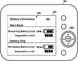
- battery information including a remaining battery level and/or a battery degradation level for the internal battery 201 and the external battery 202 shown in FIG. 7 may be displayed before the input screen for setting a battery use order shown in FIG. 6 . is displayed.
- a user can set a battery use order based on the battery information. For example, a user can set the battery use order so that a battery with a larger remaining battery level or a battery with a smaller degree of degradation is preferentially used.
- the charging performed by the circuitry shown in FIGS. 2 and 3 will be described with reference to FIG. 8 .
- the charge microcomputer 232 detects a battery attachment detection signal (DE) as described above for the internal battery 201 and the external battery 202 , and therefore, the both batteries are attached.
- the charge microcomputer 232 receives a used battery selection signal (M) for the internal battery 201 or the external battery 202 from the camera controller 153 (S 131 ).
- the internal battery 201 is prioritized (Yes in S 132 )
- the charging of the internal battery 201 is performed by the charge IC 231 (S 133 ).
- the charging of the external battery 202 is performed by the charge IC 231 (S 138 ).
- the charging of the external battery 202 is stopped (S 140 ), and then, the charging of the internal battery 201 is carried out (S 141 ).
- the charging is stopped and the processing is ended.
- the charging performed may not be a full charge (100%). Charging may be stopped at less than a full charge.
- the digital camera 102 is detachably attached with a battery grip 103 for accommodating the external battery 202 , and includes the main body 102 a , the charge IC 231 , the operation unit 160 , and the charge microcomputer 232 .
- the main body 102 a accommodates the internal battery 201 .
- the charge IC 231 charges the internal battery 201 or the external battery 202 with power input from outside.
- the operation unit 160 receives an input for setting a use order of the internal battery 201 and the external battery 202 as a priority order.
- the charge microcomputer 232 controls the charge IC 231 so as to charge the internal battery 201 or the external battery 202 according to the priority order.
- a user can set a use order of the internal battery 201 and the external battery 202 , thereby setting a priority order for charging, which can be changed according to how the camera system 100 is used. For example, when a user intends to use the digital camera 102 without attaching the battery grip 103 , the internal battery 201 can be preferentially charged to secure power for driving the digital camera 102 .
- the external battery 202 can be preferentially used and charged to secure power for driving the digital camera 102 from the aspect that the battery grip 103 to which the external battery 202 is attached can be easily replaced.
- the battery grip 103 can be normally charged only when the battery grip 103 is attached to the digital camera 102 , it may be better to charge the battery grip 103 preferentially when the battery grip 103 is attached to the digital camera 102 . Therefore, with the digital camera 102 according to the present embodiment, it is possible to charge a battery according to a condition in which a user uses the imaging device system.
- Embodiments were described above as examples of the technology disclosed in the present application. However, these embodiments are not provided by way of limitation as to the technology in the present disclosure; this technology can also be applied as appropriate to embodiments in which changes, replacements, additions, omissions, etc., have been made. The constituent elements described in the above embodiments can also be combined to yield new embodiments.
- the setting menu for a battery use order is displayed, but it may be displayed as a setting menu for a priority order for charging batteries.
- the screen ( FIG. 7 ) showing the battery remaining levels of the internal battery 201 and the external battery 202 is displayed by way of switching from and to the screen ( FIG. 5 or FIG. 6 ) for receiving an input for setting a priority order.
- both the screens may be displayed simultaneously, or displayed in a single screen.
- the digital camera is used as an example of the imaging device.
- the imaging device may be a device having an imaging function, such as a smartphone or another portable terminal.
- a computer program executed by the camera controller 153 or the charge microcomputer 232 of the digital camera 102 and a computer-readable recording medium for recording the program in the above embodiments are included in the scope of the present invention.
- the computer-readable recording medium can include a flexible disk, a hard disk, a CD-ROM, an MO, a DVD, a DVD-ROM, a DVD-RAM, a BD (Blu-rayTM Disc), and a semiconductor memory.
- the computer program described above is not limited to being recorded on the recording medium described above; the computer program may be acquired via an electric communication circuit, a wireless or wired communication circuit, networks typified by the Internet, etc.
- the present disclosure is applicable to an electronic device having an imaging function, such as a digital camera and a camera-equipped mobile phone.
Landscapes
- Engineering & Computer Science (AREA)
- Power Engineering (AREA)
- Multimedia (AREA)
- Signal Processing (AREA)
- Physics & Mathematics (AREA)
- General Physics & Mathematics (AREA)
- Human Computer Interaction (AREA)
- Studio Devices (AREA)
- Camera Bodies And Camera Details Or Accessories (AREA)
- Indication In Cameras, And Counting Of Exposures (AREA)
- Accessories Of Cameras (AREA)
- Charge And Discharge Circuits For Batteries Or The Like (AREA)
Applications Claiming Priority (4)
| Application Number | Priority Date | Filing Date | Title |
|---|---|---|---|
| JP2018-232430 | 2018-12-12 | ||
| JP2018232430 | 2018-12-12 | ||
| JPJP2018-232430 | 2018-12-12 | ||
| PCT/JP2019/033268 WO2020121603A1 (ja) | 2018-12-12 | 2019-08-26 | 撮像装置 |
Publications (2)
| Publication Number | Publication Date |
|---|---|
| US20210227136A1 US20210227136A1 (en) | 2021-07-22 |
| US11405550B2 true US11405550B2 (en) | 2022-08-02 |
Family
ID=71075468
Family Applications (1)
| Application Number | Title | Priority Date | Filing Date |
|---|---|---|---|
| US16/770,976 Active 2040-03-18 US11405550B2 (en) | 2018-12-12 | 2019-08-26 | Imaging device with battery prioritization |
Country Status (3)
| Country | Link |
|---|---|
| US (1) | US11405550B2 (ja) |
| JP (1) | JPWO2020121603A1 (ja) |
| WO (1) | WO2020121603A1 (ja) |
Families Citing this family (1)
| Publication number | Priority date | Publication date | Assignee | Title |
|---|---|---|---|---|
| US20220353395A1 (en) * | 2021-04-30 | 2022-11-03 | Shenzhen Yongnuo Photographic Equipment Co., Ltd. | Camera based on network communication |
Citations (17)
| Publication number | Priority date | Publication date | Assignee | Title |
|---|---|---|---|---|
| US5926661A (en) * | 1996-12-16 | 1999-07-20 | Olympus Optical Co., Ltd. | Camera using secondary battery |
| JPH11295808A (ja) | 1998-04-10 | 1999-10-29 | Minolta Co Ltd | 2次電池を搭載したカメラ |
| US20010005124A1 (en) * | 1999-12-08 | 2001-06-28 | Shigefumi Odeohhara | Charge control method and computer |
| JP2001313858A (ja) | 2000-04-28 | 2001-11-09 | Olympus Optical Co Ltd | 電子カメラ装置 |
| JP2002010508A (ja) | 2000-06-21 | 2002-01-11 | Sony Corp | 充電装置および充電方法 |
| JP2002351350A (ja) | 2001-05-29 | 2002-12-06 | Sony Corp | 電子機器 |
| JP2003085954A (ja) | 2001-09-14 | 2003-03-20 | Canon Inc | 磁気記録再生装置 |
| US20080315840A1 (en) * | 2007-05-18 | 2008-12-25 | Sony Corporation | Electronic device and imaging apparatus |
| US20090284225A1 (en) * | 2008-03-03 | 2009-11-19 | Panasonic Corporation | Information processing equipment and the integrated circuit |
| US20110009172A1 (en) * | 2009-07-08 | 2011-01-13 | Lg Electronics Inc. | Mobile terminal with multiple batteries |
| JP2012039358A (ja) | 2010-08-06 | 2012-02-23 | Jvc Kenwood Corp | 撮影装置および撮影装置におけるバッテリ充電方法 |
| US20130113417A1 (en) * | 2011-11-09 | 2013-05-09 | Sony Corporation | Charge control device and charge control method |
| US20130272691A1 (en) * | 2012-04-17 | 2013-10-17 | Panasonic Corporation | Power source switching device and electronic appliance |
| JP2013219952A (ja) | 2012-04-10 | 2013-10-24 | Sharp Corp | 携帯端末、携帯端末における電力の供給を通知するための方法、および、携帯端末における電力の供給を通知するための方法を実行するためのプログラム |
| US20190020819A1 (en) * | 2017-07-13 | 2019-01-17 | Panasonic Intellectual Property Management Co., Ltd. | Imaging device |
| US20190181509A1 (en) * | 2017-07-19 | 2019-06-13 | Panasonic Intellectual Property Management Co., Ltd. | Electronic device, electronic system, and method for switching battery used in electronic device |
| US20190280516A1 (en) * | 2016-12-27 | 2019-09-12 | Fujifilm Corporation | Electronic device, imaging apparatus, and method of switching power source |
-
2019
- 2019-08-26 WO PCT/JP2019/033268 patent/WO2020121603A1/ja active Application Filing
- 2019-08-26 US US16/770,976 patent/US11405550B2/en active Active
- 2019-08-26 JP JP2020501398A patent/JPWO2020121603A1/ja active Pending
Patent Citations (17)
| Publication number | Priority date | Publication date | Assignee | Title |
|---|---|---|---|---|
| US5926661A (en) * | 1996-12-16 | 1999-07-20 | Olympus Optical Co., Ltd. | Camera using secondary battery |
| JPH11295808A (ja) | 1998-04-10 | 1999-10-29 | Minolta Co Ltd | 2次電池を搭載したカメラ |
| US20010005124A1 (en) * | 1999-12-08 | 2001-06-28 | Shigefumi Odeohhara | Charge control method and computer |
| JP2001313858A (ja) | 2000-04-28 | 2001-11-09 | Olympus Optical Co Ltd | 電子カメラ装置 |
| JP2002010508A (ja) | 2000-06-21 | 2002-01-11 | Sony Corp | 充電装置および充電方法 |
| JP2002351350A (ja) | 2001-05-29 | 2002-12-06 | Sony Corp | 電子機器 |
| JP2003085954A (ja) | 2001-09-14 | 2003-03-20 | Canon Inc | 磁気記録再生装置 |
| US20080315840A1 (en) * | 2007-05-18 | 2008-12-25 | Sony Corporation | Electronic device and imaging apparatus |
| US20090284225A1 (en) * | 2008-03-03 | 2009-11-19 | Panasonic Corporation | Information processing equipment and the integrated circuit |
| US20110009172A1 (en) * | 2009-07-08 | 2011-01-13 | Lg Electronics Inc. | Mobile terminal with multiple batteries |
| JP2012039358A (ja) | 2010-08-06 | 2012-02-23 | Jvc Kenwood Corp | 撮影装置および撮影装置におけるバッテリ充電方法 |
| US20130113417A1 (en) * | 2011-11-09 | 2013-05-09 | Sony Corporation | Charge control device and charge control method |
| JP2013219952A (ja) | 2012-04-10 | 2013-10-24 | Sharp Corp | 携帯端末、携帯端末における電力の供給を通知するための方法、および、携帯端末における電力の供給を通知するための方法を実行するためのプログラム |
| US20130272691A1 (en) * | 2012-04-17 | 2013-10-17 | Panasonic Corporation | Power source switching device and electronic appliance |
| US20190280516A1 (en) * | 2016-12-27 | 2019-09-12 | Fujifilm Corporation | Electronic device, imaging apparatus, and method of switching power source |
| US20190020819A1 (en) * | 2017-07-13 | 2019-01-17 | Panasonic Intellectual Property Management Co., Ltd. | Imaging device |
| US20190181509A1 (en) * | 2017-07-19 | 2019-06-13 | Panasonic Intellectual Property Management Co., Ltd. | Electronic device, electronic system, and method for switching battery used in electronic device |
Non-Patent Citations (1)
| Title |
|---|
| International Search Report and Written Opinion for corresponding International Application No. PCT/JP2019/033268, dated Nov. 19, 2019. |
Also Published As
| Publication number | Publication date |
|---|---|
| US20210227136A1 (en) | 2021-07-22 |
| WO2020121603A1 (ja) | 2020-06-18 |
| JPWO2020121603A1 (ja) | 2021-11-04 |
Similar Documents
| Publication | Publication Date | Title |
|---|---|---|
| US11239684B2 (en) | Electronic device and control method | |
| US11736790B2 (en) | Electronic device and control method | |
| WO2019017020A1 (ja) | 電子機器及び電子システム | |
| JPWO2013099588A1 (ja) | レンズ交換式カメラ、カメラ本体、レンズユニット及びビジー信号制御方法 | |
| US11189864B2 (en) | Electronic device and control method | |
| US11070733B2 (en) | Imaging apparatus | |
| US9247135B2 (en) | Electronic device and imaging apparatus | |
| US20050200335A1 (en) | Apparatus | |
| US11405550B2 (en) | Imaging device with battery prioritization | |
| EP3699686B1 (en) | Image-capturing apparatus | |
| US11500438B2 (en) | Electronic apparatus and method for controlling the same | |
| US20190097276A1 (en) | Charging device and electronic device | |
| JP6754996B1 (ja) | 撮像装置 | |
| US11184533B2 (en) | Imaging device | |
| JP2019022017A (ja) | 撮像装置 | |
| US20230370715A1 (en) | Imaging apparatus | |
| US12088928B2 (en) | Display control device and display control method | |
| JP2007089263A (ja) | 電源装置及び携帯情報装置 | |
| JP2019022206A (ja) | 電子機器 | |
| CN116266882A (zh) | 摄像设备、控制方法和非暂时性计算机可读存储介质 | |
| JP2005018033A (ja) | カメラ制御装置、電子スチルカメラ | |
| JP6075014B2 (ja) | 充電池識別装置およびその方法 | |
| JP2013153269A (ja) | 電子装置、及びプログラム | |
| JP2023091501A (ja) | 撮像装置、制御方法およびプログラム | |
| JP2019088166A (ja) | 充電装置 |
Legal Events
| Date | Code | Title | Description |
|---|---|---|---|
| FEPP | Fee payment procedure |
Free format text: ENTITY STATUS SET TO UNDISCOUNTED (ORIGINAL EVENT CODE: BIG.); ENTITY STATUS OF PATENT OWNER: LARGE ENTITY |
|
| AS | Assignment |
Owner name: PANASONIC INTELLECTUAL PROPERTY MANAGEMENT CO., LTD., JAPAN Free format text: ASSIGNMENT OF ASSIGNORS INTEREST;ASSIGNORS:KONO, TOMONORI;NISHIKAWA, KIN;HASHIMOTO, SHINGO;REEL/FRAME:053334/0694 Effective date: 20200602 |
|
| STPP | Information on status: patent application and granting procedure in general |
Free format text: APPLICATION DISPATCHED FROM PREEXAM, NOT YET DOCKETED |
|
| STPP | Information on status: patent application and granting procedure in general |
Free format text: DOCKETED NEW CASE - READY FOR EXAMINATION |
|
| STPP | Information on status: patent application and granting procedure in general |
Free format text: NON FINAL ACTION MAILED |
|
| STPP | Information on status: patent application and granting procedure in general |
Free format text: RESPONSE TO NON-FINAL OFFICE ACTION ENTERED AND FORWARDED TO EXAMINER |
|
| STPP | Information on status: patent application and granting procedure in general |
Free format text: NOTICE OF ALLOWANCE MAILED -- APPLICATION RECEIVED IN OFFICE OF PUBLICATIONS |
|
| STCF | Information on status: patent grant |
Free format text: PATENTED CASE |