US11338564B2 - Device and method for laminating a laminating foil element onto a component, device and method for applying adhesive, system for laminating, component to be laminated with a laminating foil element, and use of a deposit part for keeping ready a laminating foil element - Google Patents
Device and method for laminating a laminating foil element onto a component, device and method for applying adhesive, system for laminating, component to be laminated with a laminating foil element, and use of a deposit part for keeping ready a laminating foil element Download PDFInfo
- Publication number
- US11338564B2 US11338564B2 US16/496,056 US201816496056A US11338564B2 US 11338564 B2 US11338564 B2 US 11338564B2 US 201816496056 A US201816496056 A US 201816496056A US 11338564 B2 US11338564 B2 US 11338564B2
- Authority
- US
- United States
- Prior art keywords
- laminating
- foil element
- laminating foil
- component
- adhesive
- Prior art date
- Legal status (The legal status is an assumption and is not a legal conclusion. Google has not performed a legal analysis and makes no representation as to the accuracy of the status listed.)
- Active, expires
Links
Images


Classifications
-
- B—PERFORMING OPERATIONS; TRANSPORTING
- B32—LAYERED PRODUCTS
- B32B—LAYERED PRODUCTS, i.e. PRODUCTS BUILT-UP OF STRATA OF FLAT OR NON-FLAT, e.g. CELLULAR OR HONEYCOMB, FORM
- B32B37/00—Methods or apparatus for laminating, e.g. by curing or by ultrasonic bonding
- B32B37/10—Methods or apparatus for laminating, e.g. by curing or by ultrasonic bonding characterised by the pressing technique, e.g. using action of vacuum or fluid pressure
- B32B37/1009—Methods or apparatus for laminating, e.g. by curing or by ultrasonic bonding characterised by the pressing technique, e.g. using action of vacuum or fluid pressure using vacuum and fluid pressure
-
- B—PERFORMING OPERATIONS; TRANSPORTING
- B29—WORKING OF PLASTICS; WORKING OF SUBSTANCES IN A PLASTIC STATE IN GENERAL
- B29C—SHAPING OR JOINING OF PLASTICS; SHAPING OF MATERIAL IN A PLASTIC STATE, NOT OTHERWISE PROVIDED FOR; AFTER-TREATMENT OF THE SHAPED PRODUCTS, e.g. REPAIRING
- B29C63/00—Lining or sheathing, i.e. applying preformed layers or sheathings of plastics; Apparatus therefor
- B29C63/48—Preparation of the surfaces
-
- B—PERFORMING OPERATIONS; TRANSPORTING
- B29—WORKING OF PLASTICS; WORKING OF SUBSTANCES IN A PLASTIC STATE IN GENERAL
- B29C—SHAPING OR JOINING OF PLASTICS; SHAPING OF MATERIAL IN A PLASTIC STATE, NOT OTHERWISE PROVIDED FOR; AFTER-TREATMENT OF THE SHAPED PRODUCTS, e.g. REPAIRING
- B29C63/00—Lining or sheathing, i.e. applying preformed layers or sheathings of plastics; Apparatus therefor
- B29C63/0073—Lining or sheathing, i.e. applying preformed layers or sheathings of plastics; Apparatus therefor of non-flat surfaces, e.g. curved, profiled
-
- B—PERFORMING OPERATIONS; TRANSPORTING
- B29—WORKING OF PLASTICS; WORKING OF SUBSTANCES IN A PLASTIC STATE IN GENERAL
- B29C—SHAPING OR JOINING OF PLASTICS; SHAPING OF MATERIAL IN A PLASTIC STATE, NOT OTHERWISE PROVIDED FOR; AFTER-TREATMENT OF THE SHAPED PRODUCTS, e.g. REPAIRING
- B29C63/00—Lining or sheathing, i.e. applying preformed layers or sheathings of plastics; Apparatus therefor
- B29C63/0091—Lining or sheathing, i.e. applying preformed layers or sheathings of plastics; Apparatus therefor in particular atmospheres
-
- B—PERFORMING OPERATIONS; TRANSPORTING
- B29—WORKING OF PLASTICS; WORKING OF SUBSTANCES IN A PLASTIC STATE IN GENERAL
- B29C—SHAPING OR JOINING OF PLASTICS; SHAPING OF MATERIAL IN A PLASTIC STATE, NOT OTHERWISE PROVIDED FOR; AFTER-TREATMENT OF THE SHAPED PRODUCTS, e.g. REPAIRING
- B29C63/00—Lining or sheathing, i.e. applying preformed layers or sheathings of plastics; Apparatus therefor
- B29C63/02—Lining or sheathing, i.e. applying preformed layers or sheathings of plastics; Apparatus therefor using sheet or web-like material
- B29C63/04—Lining or sheathing, i.e. applying preformed layers or sheathings of plastics; Apparatus therefor using sheet or web-like material by folding, winding, bending or the like
-
- B—PERFORMING OPERATIONS; TRANSPORTING
- B30—PRESSES
- B30B—PRESSES IN GENERAL
- B30B5/00—Presses characterised by the use of pressing means other than those mentioned in the preceding groups
- B30B5/02—Presses characterised by the use of pressing means other than those mentioned in the preceding groups wherein the pressing means is in the form of a flexible element, e.g. diaphragm, urged by fluid pressure
-
- B—PERFORMING OPERATIONS; TRANSPORTING
- B32—LAYERED PRODUCTS
- B32B—LAYERED PRODUCTS, i.e. PRODUCTS BUILT-UP OF STRATA OF FLAT OR NON-FLAT, e.g. CELLULAR OR HONEYCOMB, FORM
- B32B37/00—Methods or apparatus for laminating, e.g. by curing or by ultrasonic bonding
- B32B37/0076—Methods or apparatus for laminating, e.g. by curing or by ultrasonic bonding characterised in that the layers are not bonded on the totality of their surfaces
-
- B—PERFORMING OPERATIONS; TRANSPORTING
- B60—VEHICLES IN GENERAL
- B60R—VEHICLES, VEHICLE FITTINGS, OR VEHICLE PARTS, NOT OTHERWISE PROVIDED FOR
- B60R13/00—Elements for body-finishing, identifying, or decorating; Arrangements or adaptations for advertising purposes
- B60R13/02—Internal Trim mouldings ; Internal Ledges; Wall liners for passenger compartments; Roof liners
- B60R13/0237—Side or rear panels
- B60R13/0243—Doors
-
- B—PERFORMING OPERATIONS; TRANSPORTING
- B29—WORKING OF PLASTICS; WORKING OF SUBSTANCES IN A PLASTIC STATE IN GENERAL
- B29C—SHAPING OR JOINING OF PLASTICS; SHAPING OF MATERIAL IN A PLASTIC STATE, NOT OTHERWISE PROVIDED FOR; AFTER-TREATMENT OF THE SHAPED PRODUCTS, e.g. REPAIRING
- B29C43/00—Compression moulding, i.e. applying external pressure to flow the moulding material; Apparatus therefor
- B29C43/32—Component parts, details or accessories; Auxiliary operations
- B29C43/36—Moulds for making articles of definite length, i.e. discrete articles
- B29C43/3642—Bags, bleeder sheets or cauls for isostatic pressing
- B29C2043/3647—Membranes, diaphragms
-
- B—PERFORMING OPERATIONS; TRANSPORTING
- B29—WORKING OF PLASTICS; WORKING OF SUBSTANCES IN A PLASTIC STATE IN GENERAL
- B29C—SHAPING OR JOINING OF PLASTICS; SHAPING OF MATERIAL IN A PLASTIC STATE, NOT OTHERWISE PROVIDED FOR; AFTER-TREATMENT OF THE SHAPED PRODUCTS, e.g. REPAIRING
- B29C63/00—Lining or sheathing, i.e. applying preformed layers or sheathings of plastics; Apparatus therefor
- B29C63/48—Preparation of the surfaces
- B29C2063/483—Preparation of the surfaces by applying a liquid
- B29C2063/485—Preparation of the surfaces by applying a liquid the liquid being an adhesive
-
- B—PERFORMING OPERATIONS; TRANSPORTING
- B29—WORKING OF PLASTICS; WORKING OF SUBSTANCES IN A PLASTIC STATE IN GENERAL
- B29C—SHAPING OR JOINING OF PLASTICS; SHAPING OF MATERIAL IN A PLASTIC STATE, NOT OTHERWISE PROVIDED FOR; AFTER-TREATMENT OF THE SHAPED PRODUCTS, e.g. REPAIRING
- B29C51/00—Shaping by thermoforming, i.e. shaping sheets or sheet like preforms after heating, e.g. shaping sheets in matched moulds or by deep-drawing; Apparatus therefor
- B29C51/16—Lining or labelling
-
- B—PERFORMING OPERATIONS; TRANSPORTING
- B29—WORKING OF PLASTICS; WORKING OF SUBSTANCES IN A PLASTIC STATE IN GENERAL
- B29C—SHAPING OR JOINING OF PLASTICS; SHAPING OF MATERIAL IN A PLASTIC STATE, NOT OTHERWISE PROVIDED FOR; AFTER-TREATMENT OF THE SHAPED PRODUCTS, e.g. REPAIRING
- B29C65/00—Joining or sealing of preformed parts, e.g. welding of plastics materials; Apparatus therefor
- B29C65/48—Joining or sealing of preformed parts, e.g. welding of plastics materials; Apparatus therefor using adhesives, i.e. using supplementary joining material; solvent bonding
- B29C65/52—Joining or sealing of preformed parts, e.g. welding of plastics materials; Apparatus therefor using adhesives, i.e. using supplementary joining material; solvent bonding characterised by the way of applying the adhesive
- B29C65/526—Joining or sealing of preformed parts, e.g. welding of plastics materials; Apparatus therefor using adhesives, i.e. using supplementary joining material; solvent bonding characterised by the way of applying the adhesive by printing or by transfer from the surfaces of elements carrying the adhesive, e.g. using brushes, pads, rollers, stencils or silk screens
-
- B—PERFORMING OPERATIONS; TRANSPORTING
- B29—WORKING OF PLASTICS; WORKING OF SUBSTANCES IN A PLASTIC STATE IN GENERAL
- B29C—SHAPING OR JOINING OF PLASTICS; SHAPING OF MATERIAL IN A PLASTIC STATE, NOT OTHERWISE PROVIDED FOR; AFTER-TREATMENT OF THE SHAPED PRODUCTS, e.g. REPAIRING
- B29C65/00—Joining or sealing of preformed parts, e.g. welding of plastics materials; Apparatus therefor
- B29C65/78—Means for handling the parts to be joined, e.g. for making containers or hollow articles, e.g. means for handling sheets, plates, web-like materials, tubular articles, hollow articles or elements to be joined therewith; Means for discharging the joined articles from the joining apparatus
- B29C65/7841—Holding or clamping means for handling purposes
- B29C65/7847—Holding or clamping means for handling purposes using vacuum to hold at least one of the parts to be joined
-
- B—PERFORMING OPERATIONS; TRANSPORTING
- B29—WORKING OF PLASTICS; WORKING OF SUBSTANCES IN A PLASTIC STATE IN GENERAL
- B29C—SHAPING OR JOINING OF PLASTICS; SHAPING OF MATERIAL IN A PLASTIC STATE, NOT OTHERWISE PROVIDED FOR; AFTER-TREATMENT OF THE SHAPED PRODUCTS, e.g. REPAIRING
- B29C66/00—General aspects of processes or apparatus for joining preformed parts
- B29C66/004—Preventing sticking together, e.g. of some areas of the parts to be joined
-
- B—PERFORMING OPERATIONS; TRANSPORTING
- B29—WORKING OF PLASTICS; WORKING OF SUBSTANCES IN A PLASTIC STATE IN GENERAL
- B29C—SHAPING OR JOINING OF PLASTICS; SHAPING OF MATERIAL IN A PLASTIC STATE, NOT OTHERWISE PROVIDED FOR; AFTER-TREATMENT OF THE SHAPED PRODUCTS, e.g. REPAIRING
- B29C66/00—General aspects of processes or apparatus for joining preformed parts
- B29C66/01—General aspects dealing with the joint area or with the area to be joined
- B29C66/05—Particular design of joint configurations
- B29C66/10—Particular design of joint configurations particular design of the joint cross-sections
- B29C66/11—Joint cross-sections comprising a single joint-segment, i.e. one of the parts to be joined comprising a single joint-segment in the joint cross-section
- B29C66/112—Single lapped joints
- B29C66/1122—Single lap to lap joints, i.e. overlap joints
-
- B—PERFORMING OPERATIONS; TRANSPORTING
- B29—WORKING OF PLASTICS; WORKING OF SUBSTANCES IN A PLASTIC STATE IN GENERAL
- B29C—SHAPING OR JOINING OF PLASTICS; SHAPING OF MATERIAL IN A PLASTIC STATE, NOT OTHERWISE PROVIDED FOR; AFTER-TREATMENT OF THE SHAPED PRODUCTS, e.g. REPAIRING
- B29C66/00—General aspects of processes or apparatus for joining preformed parts
- B29C66/50—General aspects of joining tubular articles; General aspects of joining long products, i.e. bars or profiled elements; General aspects of joining single elements to tubular articles, hollow articles or bars; General aspects of joining several hollow-preforms to form hollow or tubular articles
- B29C66/51—Joining tubular articles, profiled elements or bars; Joining single elements to tubular articles, hollow articles or bars; Joining several hollow-preforms to form hollow or tubular articles
- B29C66/53—Joining single elements to tubular articles, hollow articles or bars
- B29C66/532—Joining single elements to the wall of tubular articles, hollow articles or bars
- B29C66/5326—Joining single elements to the wall of tubular articles, hollow articles or bars said single elements being substantially flat
-
- B—PERFORMING OPERATIONS; TRANSPORTING
- B29—WORKING OF PLASTICS; WORKING OF SUBSTANCES IN A PLASTIC STATE IN GENERAL
- B29C—SHAPING OR JOINING OF PLASTICS; SHAPING OF MATERIAL IN A PLASTIC STATE, NOT OTHERWISE PROVIDED FOR; AFTER-TREATMENT OF THE SHAPED PRODUCTS, e.g. REPAIRING
- B29C66/00—General aspects of processes or apparatus for joining preformed parts
- B29C66/80—General aspects of machine operations or constructions and parts thereof
- B29C66/83—General aspects of machine operations or constructions and parts thereof characterised by the movement of the joining or pressing tools
- B29C66/832—Reciprocating joining or pressing tools
- B29C66/8322—Joining or pressing tools reciprocating along one axis
-
- B—PERFORMING OPERATIONS; TRANSPORTING
- B29—WORKING OF PLASTICS; WORKING OF SUBSTANCES IN A PLASTIC STATE IN GENERAL
- B29L—INDEXING SCHEME ASSOCIATED WITH SUBCLASS B29C, RELATING TO PARTICULAR ARTICLES
- B29L2031/00—Other particular articles
- B29L2031/30—Vehicles, e.g. ships or aircraft, or body parts thereof
- B29L2031/3005—Body finishings
- B29L2031/3014—Door linings
-
- B—PERFORMING OPERATIONS; TRANSPORTING
- B32—LAYERED PRODUCTS
- B32B—LAYERED PRODUCTS, i.e. PRODUCTS BUILT-UP OF STRATA OF FLAT OR NON-FLAT, e.g. CELLULAR OR HONEYCOMB, FORM
- B32B2309/00—Parameters for the laminating or treatment process; Apparatus details
- B32B2309/60—In a particular environment
- B32B2309/68—Vacuum
-
- B—PERFORMING OPERATIONS; TRANSPORTING
- B32—LAYERED PRODUCTS
- B32B—LAYERED PRODUCTS, i.e. PRODUCTS BUILT-UP OF STRATA OF FLAT OR NON-FLAT, e.g. CELLULAR OR HONEYCOMB, FORM
- B32B2605/00—Vehicles
- B32B2605/003—Interior finishings
-
- B—PERFORMING OPERATIONS; TRANSPORTING
- B32—LAYERED PRODUCTS
- B32B—LAYERED PRODUCTS, i.e. PRODUCTS BUILT-UP OF STRATA OF FLAT OR NON-FLAT, e.g. CELLULAR OR HONEYCOMB, FORM
- B32B37/00—Methods or apparatus for laminating, e.g. by curing or by ultrasonic bonding
- B32B37/12—Methods or apparatus for laminating, e.g. by curing or by ultrasonic bonding characterised by using adhesives
- B32B37/1284—Application of adhesive
- B32B37/1292—Application of adhesive selectively, e.g. in stripes, in patterns
-
- B—PERFORMING OPERATIONS; TRANSPORTING
- B60—VEHICLES IN GENERAL
- B60R—VEHICLES, VEHICLE FITTINGS, OR VEHICLE PARTS, NOT OTHERWISE PROVIDED FOR
- B60R13/00—Elements for body-finishing, identifying, or decorating; Arrangements or adaptations for advertising purposes
- B60R13/02—Internal Trim mouldings ; Internal Ledges; Wall liners for passenger compartments; Roof liners
Definitions
- the present invention is a U.S. National Stage under 35 USC 371 patent application, claiming priority to Serial No. PCT/DE2018/000070, filed on 22 Mar. 2018; which claims priority of DE 10 2017 005 923.3, filed on 23 Jun. 2017 and DE 10 2017 002 772.2, filed on 22 Mar. 2017, the entirety of both of which are incorporated herein by reference.
- the invention relates to a device for laminating a laminating foil element onto a component having a profiled lamination plane using a lamination tool, by means of which the laminating foil element is laminated onto the component, the lamination tool comprising a first tool half and a second tool half.
- the invention also relates to a device for applying adhesive on a surface of a laminating foil element for laminating an automotive lining component with an application device for applying adhesive on the surface of the laminating foil element on an application plane, having a transport unit for generating a relative movement between the application device and the laminating foil element.
- the invention relates to system for laminating a component with a laminating foil element, comprising a device for laminating the laminating foil element onto the component and comprising a transport unit for transporting the laminating foil element to the lamination device.
- the invention additionally relates to a method for laminating a laminating foil element onto a component.
- the invention also relates to a method of applying adhesive on a surface of a laminating foil element for laminating a component, in particular an automotive lining component, wherein the application device for a planar spreading of the adhesive and the surface of the laminating foil element are brought in effective contact with each other on an application plane, and wherein the application device and the laminating foil element are moved relative to one another for planar application of the adhesive on the surface.
- the invention also relates to a component to be laminated with a laminating foil element, the component having at least one area to be laminated permanently, onto which the laminating foil element can be laminated permanent on a lamination plane, in particular on a profiled lamination plane.
- the invention also relates to use of a deposit part for keeping ready a laminating foil element.
- adhesive is applied on the entire foil.
- adhesive is applied on the entire surface area of the face of the laminating foil element which is brought in effective contact with the component.
- this object is achieved by a device for laminating a laminating foil element on a component with a profiled lamination plane by means of a lamination tool, by means of which the laminating foil element is laminated onto the component, the lamination tool comprising a first tool half and a second tool half and the device comprising a deflection arrangement for deflecting portions of the laminating foil element out of the profiled lamination plane.
- the deflection arrangement for deflecting portions of the laminating foil element out of the profiled lamination plane makes it possible, that even portions of the laminating foil element which are provided with adhesive do not come in effective contact with the component or only to a non-critical extent, at least temporarily.
- areas of the component which are not to be laminated do not, or not permanently, come in contact with a laminating foil element e. g. until after an adhesive has lost a substantial amount of its adhesive force.
- At least one of the two tool halves comprises the deflection arrangement, wherein a deflection cavity of the deflection arrangement is located in the at least one tool half. In this manner, contact between areas of the component which are not to be laminated and the laminating foil element can be avoided temporarily, as desired according to the invention, by simple constructive means.
- deflection cavities of the deflection arrangement have at least partially corrugated or waffle-shaped walls.
- the deflection cavities of the deflection arrangement are cooled.
- an improved embodiment provides, cumulatively or alternatively, a fluid flushing unit in the device by means of which spaces between the carrier part or component to be laminated and the laminating foil element can be flushed with a fluid, preferably with air. This helps to achieve an even more effective cooling of the adhesive.
- deflection cavities can be separated from surrounding areas by simple constructive means if deflection cavities of the deflection arrangement are spatially separated from lamination contact areas by means of sealing elements.
- deflection cavities of the deflection arrangement are embodied as vacuum cavities, the laminating foil element can very easily be partially deflected in the sense of the invention.
- the deflection arrangement can have very different embodiments.
- the deflection arrangement can be integrated in the present device very well if there is a pressure difference unit on the device or on a corresponding lamination tool, the lamination tool being designed such that by means of the pressure difference unit, at least part of the component can be deflected from a lamination plane, in particular from a profiled lamination plane, of the lamination tool into the deflection cavity.
- the object of the invention is achieved by a device for applying adhesive on a surface of a laminating foil element for laminating a component, in particular an automotive lining component, with an application device for applying adhesive on the surface of the laminating foil element on an application plane, having a transport unit for generating a relative movement between the application device and the laminating foil element, wherein the device comprises a deflection arrangement for deflecting portions of the laminating foil element out of the application plane.
- one, preferably more than one portions of a laminating foil element can be deflected out of the actual foil plane of the respective laminating foil element such that these deflected portions will not be accessible by the application device while adhesive is applied.
- the deflected portions will remain free from adhesive.
- areas which are to be laminated without adhesive that is, areas of a laminating foil element which are free from adhesive, such as, for instance, foil endings formed by a tool, can be created outside a tool of a lamination device.
- This process advantageously already takes place during the actual application of adhesive on a laminating foil element, resulting both in a substantially simplified plant construction and in a much simpler process method.
- lamination can take place in a well-known manner with a conventional “standard” lamination tool and on the other hand, a portion of the laminating foil element which is left free from adhesive can be laminated onto the component or carrier part in a non-adhesive manner, creating no or only a neglectable bonding with the carrier part or the component to be laminated, respectively.
- An application device suitable for implementing the present invention can comprise, for instance, an application roller element rolling on the surface of the respective laminating foil element and transferring adhesive adhering to the application roller element to the surface of the laminating foil element.
- application plane designates a plane, preferably a substantially horizontal plane, on which an application of adhesive to a surface of a laminating foil element takes place.
- the surface of the laminating foil element which faces the application device is located on this application plane or arranged in parallel to it.
- application means of the application device are in effective contact with the respective laminating foil element.
- adheresive here designates adhesion means with which a particularly close effective contact or connection between the laminating foil element to be applied and a component or carrier part, respectively, can be established.
- adhesion means can be of very different types, for instance special adhesives for preferably establishing adhesive bonding of plastics, but also as thermally activatable adhesives or the like.
- the expression “laminating foil element” designates an element which can be laminated onto a component for yielding a product which gives an impression of high value both in optical and in haptic terms, such as an automotive lining component or the like. That is, the laminating foil element is a decorative layer for upgrading a component. Normally, such a laminating foil element is provided in the form of a foil web and preferably as a prefabricated foil.
- component designates the actual carrier part which finally bears the laminating foil element and which in general is a finished product obtained after lamination, such as, specifically, an automotive lining component.
- the expression “transport unit” designates any unit by means of which the application device and components, in particular laminating foil elements, can be moved in relation to one another in order to transfer adhesive from the application device to the components, in particular the laminating foil elements, in a planar manner. It has proved worthwhile to move translational the components, in particular the laminating foil elements, in the application direction by means of the transport unit in order to apply adhesive on the components, in particular on the laminating foil elements. With a respective design of the transport unit, it is also possible, cumulatively or alternatively, to move the application device with respect to the components, in particular to the laminating elements.
- Deflections of the laminating foil element during application of the adhesive can be initiated very easily by means of construction, by arranging the deflection arrangement and the application device at least partially on different sides of the application plane and the laminating foil element, respectively. This makes a deflection of the laminating foil element away from the application device very simple in regard to a construction.
- the application device is constructively not in conflict with the deflection arrangement, since the deflection arrangement is positioned opposite to the application device.
- the application plane is advantageous for the application plane to be arranged between the application device and components of the deflection arrangement. In this manner, clearly defined functional spaces are created for the application device, which can further simplify the construction of the application device.
- the deflection arrangement can be implemented by various technical means for deflecting the laminating foil element out of the lamination plane. Some possibilities are contact-based gripper or suction devices or the like.
- a preferred embodiment provides for the deflection arrangement to comprise a pressure difference pump for creating a vacuum in order to lift portions of the laminating foil element's surface from application means of the application device.
- the deflection arrangement comprises at least one deposit part for depositing a laminating foil element, the deposit part comprising at least one concave cavity, preferably a plurality of concave cavities, for aspirating a portion of the laminating foil element.
- portions of the laminating foil element can be deflected particularly easily and with operational safety from the normal foil plane or from the application plane, respectively, by drawing portions of the laminating foil element into the respective cavity.
- a suitable pressure difference pump can be used to create a vacuum or a partial vacuum in the concave cavity, drawing at least portions of the laminating foil element into the cavity.
- the laminating foil element can be advantageously deflected so as to safely create portions free of adhesive on the laminating foil element.
- the laminating foil element can be deflected in these portions away from the application device to a degree which is sufficient to ensure that application means of the application device can no longer come in contact with the laminating foil element in these portions.
- the depth is less than 10 mm, preferably less than 5 mm, the risk of a plastic deformation of the laminating foil element can be avoided, which otherwise might impair surface quality of the laminating foil element.
- the laminating foil element is still sufficiently flat so that the present invention can normally be also used in existing plants for lamination of a component, provided that they have been accordingly modified.
- the deflection arrangement can be developed further when it comprises at least one deposit part for depositing a laminating foil element, the deposit part comprising at least one opening, preferably a plurality of openings, for sucking a portion of the laminating foil element.
- an opening according to the invention can be a complete through hole in a deposit part so that the deposit part will have a substantially planar, two-dimensional shape.
- the cavity in contrast, preferably has only a small vacuum opening, preferably in a concave wall of the deposit part, so that a vacuum can be created in the cavity.
- the cavity forms a recess in the surface facing the application device. Therefore, a deposit part of this kind will have an at least partially three-dimensional shape.
- the portions of the laminating foil element which are free from adhesive can have nearly any planar geometrical shape since cavities or openings provided in the deposit part can have almost any kind of contour.
- cavities and openings can also be provided in combination.
- a deposit part according to the invention can be implemented in many different ways.
- it can comprise an endless conveyor belt with openings or concave cavities.
- the dimensions of the deposit part can approximately correspond to the dimensions of one or more laminating foil elements to be applied.
- At least one deposit part comprises a tray, preferably a heated tray.
- those tray wall portions by means of which areas free from foil are to be created on the component to be laminated can be set deeper than other wall portions of the respective tray, and cavities can be evacuated in this manner.
- Those portions of the laminating foil element which are not supposed to receive adhesive are then drawn downwards, away from the application device and into the cavity, and are not covered with adhesive when passing through the application means, in particular the application roller, as has already been described above.
- the trays can be trays according to the state of the art which have been merely modified by the provision of one or more openings according to the invention.
- the trays can preferably always be transported back into a basic position by means of a separate conveying system or the present transport unit, so as to again pick up laminating foil elements and move them with respect to the application device.
- the deposit part in any case has a deposit surface on which a laminating foil element can be deposited in planar form for transport and processing according to the present invention.
- the device to be characterized by a positioning unit, in particular a print-to-part system, for precise positioning of the laminating foil element with respect to the deflection arrangement, in particular with respect to a deposit part for depositing the laminating foil element.
- a positioning unit in particular a print-to-part system
- a currently already employed print-to-part system can be used by means of which the device can be equipped with a suitable positioning unit in a particularly inexpensive manner.
- the object of the invention is also achieved by a system for laminating a component with a laminating foil element, comprising a device for laminating the laminating foil element onto the component and comprising a transport unit for transporting the laminating foil element to the device for laminating, the system being characterized by a device for laminating and/or for applying adhesive on a surface of a laminating foil element according to one of the characteristics described here.
- the components can be laminated more advantageously with laminating foil elements.
- the transport unit for transporting the laminating foil element to the device for lamination and the transport unit for causing a relative movement between the application device and the laminating foil element are the same, which substantially helps to reduce the construction effort required for providing the system and in particular the device for the application of adhesive.
- system can also be characterized either by a punching device integrated in the lamination device or by a suitable downstream punching device for punching out the laminated laminating foil element.
- the task of the invention is also achieved by a component.
- the task of the invention is also achieved by a method for laminating a laminating foil element onto a component, wherein a designated portion of the component at the laminating foil element, which is free from foil, with respect to an area of the component which is to be free from foil and with respect to other surrounding areas of the laminating foil part is deflected in a lamination tool so far, such that during lamination of the laminating foil element onto the component, this portion comes hardly in contact with the component, so that after lamination of the laminating foil part, this portion can be removed more easily from the other surrounding portions of the laminating foil part.
- a preferred type of method is proposed wherein the portion of the laminating foil part in respect to the designated foil-free area is delimited for printing from other surrounding portions of the laminating foil part, wherein with this method this delimited portion is deflected during lamination into an additional material recess of a tool half of a laminating tool by means of a vacuum, such that this portion during lamination of the laminating foil element does not or only insufficiently come in contact with the component, such as to be more easily removed from the component after lamination.
- the designated portion free from foil is preferably delimited from the surrounding portions of the laminating foil element as a separate vacuum circle.
- the portion delimited by the separate vacuum circle is then deflected within an upper mold of the laminating tool during lamination.
- a tool suitable for this purpose in particular an upper mold, has a surface enlargement structure, for instance a waffle structure, in this portion for better cooling.
- the first tool half especially in the portion of the additional material recess, is cooled such that an adhesive applied on the laminating foil element in this region loses its adhesive power at least to a substantial degree.
- a laminating tool In order to implement the method according to the fifth aspect of the present invention without problems, it is advantageous for a laminating tool to have a deflection cavity into which portions of a laminating foil element can be deflected before or during lamination on a carrier part or component.
- Deflection may take place by means of vacuum or partial vacuum of a pressure difference pump at the deflection cavity.
- the interspaces between a carrier part or component to be laminated and the laminating foil element are flushed with a fluid, in particular with air, allowing faster and therefore more effective cooling of an adhesive, such that an unintended adhesive contact between laminating foil element and carrier element can be avoided.
- the object is also achieved by means of a method of applying adhesive on a surface of a laminating foil element for laminating a component, in particular an automotive lining component, where an application device for the planar application of adhesive and the surface of the laminating foil element are brought in effective contact with each other on an application plane, and where the application device and the laminating foil element are moved in relation to one another for a planar application of the adhesive on the surface of the laminating foil element, with portions of the laminating foil element's surface being deflected from the application plane such that adhesive is only applied on some portions of the laminating foil element's surface.
- portions which are to be laminated without an adhesive that is, portions of a laminating foil element which are to be left free from adhesive, can be created outside a laminating device.
- the consumption of adhesive can be further reduced if there are even less areas covered with adhesive on a laminating foil element by also leaving spaces between cavities and/or openings, as well as outputs, which are free from adhesive.
- the surface of the laminating foil element is deflected out of the application plane such that portions of the surface of the laminating foil element are left free from adhesive, these portions being located especially within or in boundary areas of the laminating foil element.
- portions both inside and outside of the laminating foil element can be left free from adhesive such that these portions can be drawn off the laminated component and disposed off quite easily after a laminating process without these separated portions of the laminating foil element being contaminated with adhesive.
- Portions of the laminating foil element free from adhesive can be produced especially on boundaries of the adhesive foil element, that is, specifically in a foil output of a tool, if the surface of the laminating foil element is partially deflected out of the application plane such that regions free from adhesive are produced on the surface of the laminating foil element, bordering on an adhesive layer produced on the surface.
- portions free from adhesive can also be produced without any problems within a laminating foil element surface if the surface of the laminating foil element is partially deflected out of the application plane, such that portions free from adhesive are produced on the surface of the laminating foil element which are at least partially or entirely surrounded by adhesive.
- portions of the surface according to the invention are deflected out of the application plane, portions free from adhesive can be created as desired in a very simple manner on the respective laminating foil element.
- the laminating foil element is already partially lifted off the application device before or during application of the adhesive, in order to provide the surface of the laminating foil element only partially with an adhesive layer.
- the laminating foil element has been moved partially away from the application device during the application of the adhesive, partial portions of the surface of the laminating foil element can only be partly covered with an adhesive layer, while directly adjacent portions of the laminating foil element remain free from adhesive.
- portions of the laminating foil element will be moved away from the application device which will then no longer be reached by application means of the application device, creating portions on the surface of the laminating foil element which are free from adhesive.
- both portions with and without adhesive can be produced on the laminating foil element, which process is simplified by a pressure difference pump.
- the object is also achieved by a component for lamination with a laminating foil element, the component having at least one area to be laminated permanently, onto which area the laminating foil element can be permanently laminated on a lamination plane, in particular on a profiled lamination plane, the component temporarily having at least one differently structured area embodied such that only portions of the same, or preferably none at all, come in effective contact with the laminating foil element. In this manner, an adhesive force between the laminating foil element and the carrier part can be partly avoided.
- the at least one differently structured portion has a surface or surface texture different from the at least one portion to be laminated permanent such that, in particular, better cooling can be achieved in the differently structured portion.
- the cooling effect can be substantially increased by a significantly larger cooling surface.
- Such a honeycomb-like or corrugated structure is characterized by recesses which traverse the surface of the laminating foil element.
- the at least one differently structured portion is formed by at least two honeycomb elements, preferably an assemblage of honeycomb elements, which makes it possible to achieve a good stability and surface enlargement of the laminating foil element.
- the component and the laminating foil element, respectively can be provided with a very stable contour, further improving a handling of the component.
- the object of the invention is also achieved by use of a deposit part for providing a laminating foil element on a lamination system for laminating an automotive lining component or the like to create portions free from adhesive on a surface of this laminating foil element.
- portions free from adhesive can be created very easily on a laminating foil element.
- a method of producing a planar adhesive layer on a semi-finished product should advantageously also be mentioned, in which a means of adhesion, such as, for example, a suitable adhesive, is transferred to a surface of the semi-finished product by means of an application device, in particular an application roller for the application of adhesion means; wherein the application device and the surface of the semi-finished product are brought in effective mutual contact, for which purpose the semi-finished product is placed on a deposit part; and wherein subsequently the application device for planar application of the adhesion means and the semi-finished product are moved towards and in relation to one another; and wherein the surface of the semi-finished product is only partially brought in effective contact with the adhesion means by displacing portions of the semi-finished product into cavities or through openings of the deposit part.
- a means of adhesion such as, for example, a suitable adhesive
- the present invention is also characterized by the fact that by means of a deflection arrangement, portions of a laminating foil element are deflected out of an application plane in which adhesive is applied on the laminating foil element, and/or out of a lamination plane defined by a carrier part profile, on which plane a laminating foil element is laminated onto a carrier part or component, in such a way that areas free from foil can be produced in a very simple manner on the component.
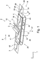
- FIG. 1 schematically shows a perspective view of a device for applying adhesive on a surface of a laminating element, having a deflection arrangement for deflecting portions of the laminating foil element out of an application plane on which adhesive is transferred to the surface of the laminating element by an application device;
- FIG. 2 schematically shows a lateral view of the device in FIG. 1 ;
- FIG. 3 schematically shows a top view of the device in FIGS. 1 and 2 ;
- FIG. 4 schematically shows a detailed view of the application device in FIGS. 1 to 3 ;
- FIG. 5 schematically shows a perspective view of a component to be laminated with a laminating foil element, i. e. of the laminating foil with the component arranged below it, respectively;
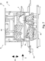
- FIG. 6 schematically shows a partially cut view of a device for applying a laminating foil element with an open lamination tool, comprising a deflection arrangement for deflecting the laminating foil element out of a profiled lamination plane;
- FIG. 7 schematically shows another partially cut view of the device in FIG. 6 with a closing lamination tool
- FIG. 8 schematically shows another partially cut view of the device in FIGS. 6 and 7 with a closed lamination tool
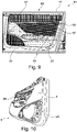
- FIG. 9 schematically shows a view of the laminating foil element shown in FIGS. 6 through 8 , formed with the lamination tool and applied, positioned in the upper tool half of the lamination tool;
- FIG. 10 schematically shows a view of the component laminated with the device in FIGS. 6 through 9 , with differently structured areas already separated.
- the device 1 shown in FIGS. 1 through 4 , for applying adhesive 2 on a surface 3 of a laminating foil element 4 (indicated here only by way of example) for laminating a component 5 is merely one of several processing stations 6 (not shown) of an only schematically indicated system 7 for laminating a component 5 with a respective laminating foil element 4 .
- FIG. 1 four laminating foil elements 4 of this type are shown.
- Component 5 which is shown only exemplarily in the context of the present invention, can be any component 5 which can be used in many different ways.
- the present component 5 is an automotive lining component, in particular an automotive inner lining component, which is to be upgraded by the laminating foil element 4 .
- the laminating foil element 4 can be a decorative layer (not referenced again) for giving an impression of higher value, in optical, but generally also in haptic terms.
- the device 1 for applying adhesive 2 is arranged before a device (not shown) for laminating the laminating foil element 4 onto the component 5 of the system 7 .
- the device 1 comprises an application device 10 for applying adhesive 2 onto the surface 3 of the laminating foil element 4 , wherein for applying the adhesive 2 , application means 11 are provided, embodied in this specific example of embodiment by an application roller element 12 .
- the application device 10 also comprises an adhesive reservoir 13 containing adhesive 2 .
- the adhesive reservoir 13 is positioned above the application means 11 and the application roller element 12 thereof, such that the application roller element 12 can be charged with adhesive 2 by the force of gravity.
- the application roller element 12 forms the lower end of the adhesive reservoir 13 .
- the device 1 is further characterized by an application plane 15 (see especially FIG. 2 ) opposite to the application device 10 . More precisely, the application plane 15 is located beneath the application device 10 .
- the adhesive 2 is transferred from the application roller element 12 to the surface 3 of the laminating foil element 4 which faces the application device 10 .
- the application plane 15 is substantially built by a transport unit 18 by means of which individual laminating foil elements 4 are transported through the device 1 and in particular through the system 7 .
- the transport unit 18 allows, specifically in the device 1 , a relative movement between the laminating foil element 4 and the application device 10 located above it.
- the transport unit 18 has an endless circulating transport belt 19 ; in this example of embodiment, advantageously, the transport belt 19 of a DMY conveyor (not separately referenced) of the system 7 . This helps to keep the construction of the present device 1 simpler.
- the device 1 according to the invention is further characterized by a deflection arrangement 20 by means of which the respective laminating foil element 4 can be partially deflected with respect to the application device 10 with a deflection direction 21 , the deflection direction 21 leading away from the application device 10 .
- a deflection movement 22 of the areas 25 , 26 , 27 etc. of the laminating foil element 4 in the deflection direction 21 transverse to the machine direction 7 or the application plane 15 is envisaged for implementing these areas 25 , 26 , 27 etc. without adhesive.
- the areas 25 , 26 , 27 etc. are marked, i.e. surrounded by border edge lines, for better visibility.
- the areas 25 , 26 , 27 etc. very precisely indicate the contours 28 (indicated only by way of example) of areas 29 (indicated only by way of example) on the laminating foil element 4 which are left free from adhesive.
- the surface 3 of the laminating foil element 4 is deflected in such a way out of the application plane 15 that adhesive 2 is only applied on portions of the surface 3 of the laminating foil element 4 .
- the application device 10 applies, i. e. produces, an adhesive layer 31 on the laminating foil element 4 only in those portions 30 which are or were not deflected out of the application plane 15 according to the invention.
- the application plane 15 is arranged between the application device 10 and the deflection arrangement 20 .
- the deflection arrangement 20 and the application device 10 are located on different sides 33 and 34 of the application plane 15 or the laminating foil element 4 , respectively; the application device 10 being positioned above the application plane 15 on the first side 33 and the deflection arrangement 20 on the second side 34 of the application plane 15 which is opposite the first side 33 .
- a pressure difference pump 35 is located by means of which a vacuum or a partial vacuum can be created on the surface 36 of the laminating foil element 4 which is opposite the application device 10 , so that the surface 3 of the laminating foil element 4 can be deflected in portions from the application means 11 or from the application roller element 12 of the application device 10 , respectively.
- the deflection arrangement 20 also comprises deposit parts 40 (here only referenced by way of example) for depositing the laminating foil elements 4 , the deposit parts 40 each having at least one concave cavity 41 which is only suggested in the drawing and which is substantially congruent with the areas 25 , 26 , 27 etc. which will subsequently be free from adhesive; so that these areas 25 , 26 , 27 etc. are drawn into the cavities 41 at least to a certain extent by means of the partial vacuum.
- the laminating foil element 4 is deflected out of the application plane 15 at least above the provided cavities 41 .
- a depth 42 (see FIG. 4 ) of approximately 2 mm is already sufficient for a vacuum or partial vacuum space, such as, for instance, the cavity 41 or a through opening (not shown) in the deposit part 40 which has some other form.
- This depth 42 is preferably measured in the direction 21 of deflection from a deposit surface 43 for depositing the laminating foil element 4 on the deposit part 40 .
- the device 1 also has a positioning unit not shown here in detail, which is implemented in this example of embodiment by a print-to-part system which is already known and operates with sufficient reliability.
- FIG. 5 the abovementioned component 5 with the laminating foil element 4 , which has partially been laminated onto the component, is shown by way of example, with this example of embodiment showing an automotive inner lining component (not referenced separately).
- the laminating foil element 4 which has been partially applied, has portions 50 (only referenced by way of example) laminated permanently onto the component 5 , which are substantially smooth, as well as other portions 51 not laminated onto the component 5 which are structured differently.
- the areas 52 of the component 5 which are free from foil will subsequently be located in the positions corresponding to the differently structured portions 51 when the latter have been removed.
- the differently structured portions 51 have been produced by deflecting or sucking, respectively, these differently structured portions 51 into a tool half of a lamination tool which is provided with a deflection cavity so as to avoid or minimize effective adhesive contact between the component surface and the adhesive surface of the laminating foil element 4 .
- the portions 25 , 26 , 27 etc. of the laminating foil element 4 which are free from adhesive can be made congruent with the differently structured portions 51 of the component 5 during lamination.
- the component 5 defines a profiled lamination plane 53 onto which the laminating foil element 4 is to be permanent laminated in the end while leaving the areas 52 free from foil.
- the component 5 which is only shown by way of example in FIG. 5 can be substantially produced according to any of the aspects on which the invention is based.
- a so called hand rail field 55 a door means field 56 , a loudspeaker field 57 or the like can be located later on.
- FIGS. 6 through 8 a device 60 for applying a laminating foil element 4 and a component 5 laminated with the same (see FIG. 8 ) are shown.
- FIG. 6 shows the device 60 with an open laminating tool 61 comprising a first tool half 62 (upper tool half) and a second tool half 63 (lower tool half).
- the tool halves 62 and 63 are arranged in the device 60 in such a way that they can move towards and away from each other in the closing and opening direction 66 by means of hydraulic cylinders 64 and 65 .
- a carrier part 5 A is supported which forms the final laminated component 5 together with the laminating foil element 4 .
- the laminating foil element 4 is fed to the lamination tool 61 in the machine direction 8 as a flat foil element (not referenced separately), the machine direction 8 in this example of embodiment going from left to right.
- the device 60 has a deflection arrangement 70 for deflecting portions of the laminating foil element 4 out of the profiled lamination plane 53 .
- the profiled lamination plane 53 extends together with the surface of the carrier part 5 A, with the tool halves 62 and 63 comprising respective mold elements 71 (referenced only on the first tool half 62 ), which also correspond to the profiled lamination plane 53 .
- the deflection arrangement 70 comprises several deflection cavities 72 , 73 and 74 whose openings (not shown here) preferably extend in or in parallel to the profiled lamination plane 53 , in particular with their opening diameter contours.
- deflection cavities 72 , 73 and 74 are limited by at least partially corrugated or waffle-shaped walls 75 (only referenced by way of example).
- the laminating tool 61 has sealing elements 77 , 78 , 79 (only shown by way of example) in the form of sealing struts or the like in order to seal the deflection cavities 72 , 73 and 74 with respect to laminating portions 80 , 81 and 82 by differential pressure, at least in a closed or nearly closed state of the lamination tool 61 .
- the sealing elements 77 , 78 , 79 are wall-shaped in the form of sealing struts or the like but are shown in cross-sectional view and therefore only shown as lines.
- the sealing elements form sealing edges 83 (see FIG. 9 by way of example) on the deflection cavities 72 , 73 and 74 and at the laminating foil element 4 , respectively, the edges having a thickness of more than 1.5 mm, in particular approximately 3.5 mm.
- the edges can later be used as pattern edges for cutting out the laminating foil element 4 .
- the thickness of the sealing edges 83 is preferably lower than 10 mm.
- the device For producing the additional pressure difference specifically within the deflection cavities 72 , 73 and 74 , the device also has a suitable pressure difference unit 85 which is with reference to its individual components only schematically indicated in FIG. 6 .
- the lamination tool 61 has already been largely closed by means of differential pressure, the laminating foil element 4 has already been pre-blown into the first tool half 62 ; in particular, it has been sucked into the upper mold element 71 and, with a view to the portions which are not to be laminated, it has subsequently also been sucked into the deflection cavities 72 , 73 and 74 .
- This effect is reinforced by a cooling unit 86 for cooling these differently structured portions 51 and any adhesive applied thereon, so that this adhesive cools off very rapidly, losing its adhesive effect.
- the device 60 also comprises a fluid flushing unit 90 (air flushing unit; see only FIG. 6 ) for flushing an interspace 91 (see FIG. 9 ) between the carrier part 5 A or the component 5 , respectively, to be laminated, and the laminating foil element 4 , preferably with the lamination tool 61 closed and at least portions of the laminating foil element 4 pressed on the carrier part 5 A, as is the case shown in FIG. 8 .
- a fluid flushing unit 90 air flushing unit; see only FIG. 6
- an interspace 91 see FIG. 9
- FIG. 9 shows a bottom view of the first tool half with the laminating foil element 4 shown therein, but without the carrier part 5 A.
- FIG. 10 shows the component 5 with the laminating foil element 4 laminated onto it, the differently structured portions 51 all having been removed, for which reason non-laminated areas 93 with the visible carrier part 5 A of the component 5 can be clearly recognized.
Landscapes
- Engineering & Computer Science (AREA)
- Manufacturing & Machinery (AREA)
- Physics & Mathematics (AREA)
- Fluid Mechanics (AREA)
- Mechanical Engineering (AREA)
- Lining Or Joining Of Plastics Or The Like (AREA)
- Laminated Bodies (AREA)
Applications Claiming Priority (5)
| Application Number | Priority Date | Filing Date | Title |
|---|---|---|---|
| DE102017002772.2 | 2017-03-22 | ||
| DE102017002772 | 2017-03-22 | ||
| DE102017005923.3A DE102017005923A1 (de) | 2017-03-22 | 2017-06-23 | Vorrichtung und verfahren zum auftragen von klebstoff, vorrichtung und verfahren zum aufkaschieren eines kaschierfolienelements auf ein bauteil, anlage zum kaschieren sowie verwendung eines ablageteils zum bereitstellen eines kaschierfolienelements |
| DE102017005923.3 | 2017-06-23 | ||
| PCT/DE2018/000070 WO2018171826A2 (de) | 2017-03-22 | 2018-03-22 | Vorrichtung und verfahren zum aufkaschieren eines kaschierfolienelements auf einem bauteil, vorrichtung und verfahren zum auftragen von klebstoff, anlage zum kaschieren, bauteil zum kaschieren mit einem kaschierfolienelement sowie verwendung eines ablageteils zum bereitstellen eines kaschierfolienelements |
Publications (2)
| Publication Number | Publication Date |
|---|---|
| US20200108590A1 US20200108590A1 (en) | 2020-04-09 |
| US11338564B2 true US11338564B2 (en) | 2022-05-24 |
Family
ID=63449781
Family Applications (1)
| Application Number | Title | Priority Date | Filing Date |
|---|---|---|---|
| US16/496,056 Active 2038-10-31 US11338564B2 (en) | 2017-03-22 | 2018-03-22 | Device and method for laminating a laminating foil element onto a component, device and method for applying adhesive, system for laminating, component to be laminated with a laminating foil element, and use of a deposit part for keeping ready a laminating foil element |
Country Status (6)
| Country | Link |
|---|---|
| US (1) | US11338564B2 (de) |
| EP (1) | EP3600831B1 (de) |
| CN (1) | CN110475657A (de) |
| DE (2) | DE102017005923A1 (de) |
| MX (1) | MX2019011069A (de) |
| WO (1) | WO2018171826A2 (de) |
Families Citing this family (3)
| Publication number | Priority date | Publication date | Assignee | Title |
|---|---|---|---|---|
| CN113290871A (zh) * | 2021-06-04 | 2021-08-24 | 福建万顺运动科技有限公司 | 充气冲浪板的辊压封边装置 |
| DE102022101280B4 (de) * | 2022-01-20 | 2023-11-02 | Lisa Dräxlmaier GmbH | Verfahren zum herstellen eines verbunds mindestens zweier schichten |
| CN115921220B (zh) * | 2022-12-21 | 2023-06-13 | 维达纸业(浙江)有限公司 | 一种生产卫生巾用的喷涂装置及方法 |
Citations (9)
| Publication number | Priority date | Publication date | Assignee | Title |
|---|---|---|---|---|
| US3753830A (en) | 1970-07-13 | 1973-08-21 | United States Steel Corp | Apparatus for laminating a plastic sheet onto a surface of a hollow body |
| US5080749A (en) * | 1987-01-16 | 1992-01-14 | Takashimaya Nippatsu Kogyo Co., Ltd. | Apparatus for producing interior vehicular trim |
| US5201981A (en) | 1991-08-16 | 1993-04-13 | Citadel Architectural Products, Inc. | Method of forming synthetic plastic film-projected building siding |
| US5700542A (en) | 1994-06-08 | 1997-12-23 | Pirchl; Gerhard | Metal part with covering and method of its manufacture |
| FR2757103A1 (fr) | 1996-12-16 | 1998-06-19 | Allibert Ind | Procede pour realiser une piece finie composite comportant un revetement recouvrant une face d'une couche de mousse en matiere plastique et piece finie |
| US5811053A (en) * | 1995-03-15 | 1998-09-22 | Kasai Kogyo Co., Ltd. | Method for molding a laminated assembly |
| US5951802A (en) * | 1995-04-11 | 1999-09-14 | Marley Automotive Components Limited | Vehicle trim panel |
| FR2863195A1 (fr) | 2003-12-04 | 2005-06-10 | Mp Vanquish Sa | Procede de recouvrement d'un element par une feuille thermoplastique et element recouvert obtenu |
| WO2014131918A1 (es) | 2013-02-28 | 2014-09-04 | Grupo Antolín-Ingeniería, S. A. | Procedimiento para la fabricación de un guarnecido interior de puerta para vehículo, instalación para la fabricación de dicho guarnecido interior de puerta y producto obtenido |
Family Cites Families (9)
| Publication number | Priority date | Publication date | Assignee | Title |
|---|---|---|---|---|
| US4823729A (en) * | 1987-01-20 | 1989-04-25 | Dvsg Patentverwaltungs | Machine for applying a fused configuration of powder on a shoe substrate |
| DE3828929C2 (de) | 1988-08-26 | 1999-04-22 | Festo Ag & Co | Vorrichtung zum Auftragen von Klebstoff auf zu verklebende Oberflächen |
| US5336319A (en) * | 1992-05-26 | 1994-08-09 | Xerox Corporation | Apparatus for applying an adhesive layer to a substrate surface |
| JP4071056B2 (ja) * | 2002-07-04 | 2008-04-02 | ユニ・チャーム株式会社 | 使い捨ておむつの製造方法 |
| EP1410849A1 (de) * | 2002-10-18 | 2004-04-21 | Solipat Ag | Bearbeitungsanlage für Warenbahnen, beinhaltend eine modulare Einrichtung zum Auftragen von Fluiden auf Warenbahnen |
| EP2532329B1 (de) * | 2011-06-10 | 2018-09-19 | The Procter and Gamble Company | Verfahren und vorrichtung zum herstellen von absorptionsstrukturen mit absorptionsmaterial |
| EP2913184A3 (de) | 2014-02-26 | 2015-10-21 | KIEFEL GmbH | Verfahren zum Aufbringen eines Klebers auf eine Kaschierfolie, Verfahren zum Kaschieren eines Trägerteils und Kaschieranlage |
| DE102014104321A1 (de) * | 2014-03-27 | 2015-10-01 | Leonhard Kurz Stiftung & Co. Kg | Formkörper und Verfahren zu dessen Herstellung |
| CN204220639U (zh) * | 2014-09-12 | 2015-03-25 | 凯孚尔有限公司 | 用于使带有至少一个标记的片材变形的装置 |
-
2017
- 2017-06-23 DE DE102017005923.3A patent/DE102017005923A1/de not_active Withdrawn
-
2018
- 2018-03-22 EP EP18720083.7A patent/EP3600831B1/de active Active
- 2018-03-22 US US16/496,056 patent/US11338564B2/en active Active
- 2018-03-22 MX MX2019011069A patent/MX2019011069A/es unknown
- 2018-03-22 CN CN201880019530.7A patent/CN110475657A/zh active Pending
- 2018-03-22 WO PCT/DE2018/000070 patent/WO2018171826A2/de not_active Ceased
- 2018-03-22 DE DE112018001516.5T patent/DE112018001516A5/de active Pending
Patent Citations (9)
| Publication number | Priority date | Publication date | Assignee | Title |
|---|---|---|---|---|
| US3753830A (en) | 1970-07-13 | 1973-08-21 | United States Steel Corp | Apparatus for laminating a plastic sheet onto a surface of a hollow body |
| US5080749A (en) * | 1987-01-16 | 1992-01-14 | Takashimaya Nippatsu Kogyo Co., Ltd. | Apparatus for producing interior vehicular trim |
| US5201981A (en) | 1991-08-16 | 1993-04-13 | Citadel Architectural Products, Inc. | Method of forming synthetic plastic film-projected building siding |
| US5700542A (en) | 1994-06-08 | 1997-12-23 | Pirchl; Gerhard | Metal part with covering and method of its manufacture |
| US5811053A (en) * | 1995-03-15 | 1998-09-22 | Kasai Kogyo Co., Ltd. | Method for molding a laminated assembly |
| US5951802A (en) * | 1995-04-11 | 1999-09-14 | Marley Automotive Components Limited | Vehicle trim panel |
| FR2757103A1 (fr) | 1996-12-16 | 1998-06-19 | Allibert Ind | Procede pour realiser une piece finie composite comportant un revetement recouvrant une face d'une couche de mousse en matiere plastique et piece finie |
| FR2863195A1 (fr) | 2003-12-04 | 2005-06-10 | Mp Vanquish Sa | Procede de recouvrement d'un element par une feuille thermoplastique et element recouvert obtenu |
| WO2014131918A1 (es) | 2013-02-28 | 2014-09-04 | Grupo Antolín-Ingeniería, S. A. | Procedimiento para la fabricación de un guarnecido interior de puerta para vehículo, instalación para la fabricación de dicho guarnecido interior de puerta y producto obtenido |
Non-Patent Citations (1)
| Title |
|---|
| International Search Report and Written Opinion for Application No. PCT/DE2018/000070 dated Sep. 7, 2018. |
Also Published As
| Publication number | Publication date |
|---|---|
| EP3600831A2 (de) | 2020-02-05 |
| US20200108590A1 (en) | 2020-04-09 |
| WO2018171826A3 (de) | 2018-11-15 |
| WO2018171826A2 (de) | 2018-09-27 |
| EP3600831B1 (de) | 2023-09-06 |
| DE102017005923A1 (de) | 2018-09-27 |
| DE112018001516A5 (de) | 2020-01-16 |
| EP3600831C0 (de) | 2023-09-06 |
| MX2019011069A (es) | 2019-11-12 |
| CN110475657A (zh) | 2019-11-19 |
Similar Documents
| Publication | Publication Date | Title |
|---|---|---|
| US11338564B2 (en) | Device and method for laminating a laminating foil element onto a component, device and method for applying adhesive, system for laminating, component to be laminated with a laminating foil element, and use of a deposit part for keeping ready a laminating foil element | |
| JP5422767B1 (ja) | 貼り合わせ分離方法及び分離装置 | |
| JP5526008B2 (ja) | 積層シートおよび積層シートの形成方法 | |
| JP5708892B2 (ja) | シート材の接着剤塗布方法 | |
| US11759967B2 (en) | Method and apparatus for producing sheet material articles from planiform blanks | |
| KR20140034240A (ko) | 섬유 강화 플라스틱 성형품을 제조하는 중에 평면형 직물로부터 절단된 섬유 콘투어를 이송하기 위한 방법 및 장치 | |
| US20200319043A1 (en) | Perforated support layer that facilitates static and dynamic bending | |
| AU2014255997A1 (en) | Storage device having three-dimensional elevations | |
| CN103717387B (zh) | 用于形成带图案化微波能量相互作用材料的层叠件的系统和方法 | |
| JP2013082612A5 (de) | ||
| TWI718688B (zh) | 貼合設備及其中介機構、及貼合方法 | |
| JP2016515054A (ja) | セキュリティ用紙の基体およびその製造方法 | |
| JP2019048419A (ja) | 光硬化型立体印刷装置 | |
| CN107148667B (zh) | 基板的吸附装置、基板的贴合装置和贴合方法以及电子器件的制造方法 | |
| ITMO20100024A1 (it) | Apparato per formare ed etichettare un oggetto ed oggetto così ottenuto | |
| JP6020138B2 (ja) | テーパートレーの成形方法 | |
| ES2357860T3 (es) | Procedimiento de fabricación de un artículo de material compuesto reforzado con fibras que presenta una porción localmente situada, marcadamente curvada. | |
| CN106346945B (zh) | 用于制造出全息图的印版和用于制造印版的方法 | |
| US20220135342A1 (en) | Trolley device for conveying laminar elements and conveyor assembly | |
| KR20200032667A (ko) | 판지 시트로부터 블랭크를 생산하기 위한 도구 및 방법 | |
| EP2905232A1 (de) | Siegelwerkzeugoberteil einer Schalenverschließmaschine und entsprechendes Verfahren | |
| JP6047338B2 (ja) | 食品ケース加工用シート状ブランク製造装置 | |
| USD979394S1 (en) | Gift card carrier | |
| KR20230159681A (ko) | 접시-형상 제품 패키지를 제조하기 위한 장치 및 방법 | |
| EP3392047B1 (de) | Absaugarraylayouts |
Legal Events
| Date | Code | Title | Description |
|---|---|---|---|
| FEPP | Fee payment procedure |
Free format text: ENTITY STATUS SET TO UNDISCOUNTED (ORIGINAL EVENT CODE: BIG.); ENTITY STATUS OF PATENT OWNER: LARGE ENTITY |
|
| AS | Assignment |
Owner name: KIEFEL GMBH, GERMANY Free format text: ASSIGNMENT OF ASSIGNORS INTEREST;ASSIGNORS:REHRL, HUBERT;DANDL, ANDREAS;REHRL, JOSEF;REEL/FRAME:051409/0390 Effective date: 20191108 |
|
| STPP | Information on status: patent application and granting procedure in general |
Free format text: DOCKETED NEW CASE - READY FOR EXAMINATION |
|
| AS | Assignment |
Owner name: PERSICO AUTOMOTIVE GMBH, GERMANY Free format text: ASSIGNMENT OF ASSIGNORS INTEREST;ASSIGNOR:KIEFEL GMBH;REEL/FRAME:054646/0826 Effective date: 20201009 |
|
| AS | Assignment |
Owner name: PERSICO SPA, ITALY Free format text: ASSIGNMENT OF ASSIGNORS INTEREST;ASSIGNOR:PERSICO AUTOMOTIVE GMBH;REEL/FRAME:056285/0375 Effective date: 20201027 |
|
| STPP | Information on status: patent application and granting procedure in general |
Free format text: NON FINAL ACTION MAILED |
|
| STPP | Information on status: patent application and granting procedure in general |
Free format text: RESPONSE TO NON-FINAL OFFICE ACTION ENTERED AND FORWARDED TO EXAMINER |
|
| STPP | Information on status: patent application and granting procedure in general |
Free format text: FINAL REJECTION MAILED |
|
| STPP | Information on status: patent application and granting procedure in general |
Free format text: NOTICE OF ALLOWANCE MAILED -- APPLICATION RECEIVED IN OFFICE OF PUBLICATIONS |
|
| STPP | Information on status: patent application and granting procedure in general |
Free format text: PUBLICATIONS -- ISSUE FEE PAYMENT RECEIVED |
|
| STPP | Information on status: patent application and granting procedure in general |
Free format text: PUBLICATIONS -- ISSUE FEE PAYMENT VERIFIED |
|
| STCF | Information on status: patent grant |
Free format text: PATENTED CASE |
|
| MAFP | Maintenance fee payment |
Free format text: PAYMENT OF MAINTENANCE FEE, 4TH YEAR, LARGE ENTITY (ORIGINAL EVENT CODE: M1551); ENTITY STATUS OF PATENT OWNER: LARGE ENTITY Year of fee payment: 4 |