US11224978B2 - Robot - Google Patents
Robot Download PDFInfo
- Publication number
- US11224978B2 US11224978B2 US16/089,388 US201716089388A US11224978B2 US 11224978 B2 US11224978 B2 US 11224978B2 US 201716089388 A US201716089388 A US 201716089388A US 11224978 B2 US11224978 B2 US 11224978B2
- Authority
- US
- United States
- Prior art keywords
- joint part
- arm
- connector
- case
- fixed
- Prior art date
- Legal status (The legal status is an assumption and is not a legal conclusion. Google has not performed a legal analysis and makes no representation as to the accuracy of the status listed.)
- Active, expires
Links
Images


Classifications
-
- B—PERFORMING OPERATIONS; TRANSPORTING
- B25—HAND TOOLS; PORTABLE POWER-DRIVEN TOOLS; MANIPULATORS
- B25J—MANIPULATORS; CHAMBERS PROVIDED WITH MANIPULATION DEVICES
- B25J17/00—Joints
-
- B—PERFORMING OPERATIONS; TRANSPORTING
- B25—HAND TOOLS; PORTABLE POWER-DRIVEN TOOLS; MANIPULATORS
- B25J—MANIPULATORS; CHAMBERS PROVIDED WITH MANIPULATION DEVICES
- B25J9/00—Programme-controlled manipulators
- B25J9/10—Programme-controlled manipulators characterised by positioning means for manipulator elements
- B25J9/102—Gears specially adapted therefor, e.g. reduction gears
-
- B—PERFORMING OPERATIONS; TRANSPORTING
- B25—HAND TOOLS; PORTABLE POWER-DRIVEN TOOLS; MANIPULATORS
- B25J—MANIPULATORS; CHAMBERS PROVIDED WITH MANIPULATION DEVICES
- B25J13/00—Controls for manipulators
- B25J13/08—Controls for manipulators by means of sensing devices, e.g. viewing or touching devices
- B25J13/088—Controls for manipulators by means of sensing devices, e.g. viewing or touching devices with position, velocity or acceleration sensors
-
- B—PERFORMING OPERATIONS; TRANSPORTING
- B25—HAND TOOLS; PORTABLE POWER-DRIVEN TOOLS; MANIPULATORS
- B25J—MANIPULATORS; CHAMBERS PROVIDED WITH MANIPULATION DEVICES
- B25J19/00—Accessories fitted to manipulators, e.g. for monitoring, for viewing; Safety devices combined with or specially adapted for use in connection with manipulators
- B25J19/0025—Means for supplying energy to the end effector
- B25J19/0029—Means for supplying energy to the end effector arranged within the different robot elements
-
- B—PERFORMING OPERATIONS; TRANSPORTING
- B25—HAND TOOLS; PORTABLE POWER-DRIVEN TOOLS; MANIPULATORS
- B25J—MANIPULATORS; CHAMBERS PROVIDED WITH MANIPULATION DEVICES
- B25J9/00—Programme-controlled manipulators
- B25J9/02—Programme-controlled manipulators characterised by movement of the arms, e.g. cartesian coordinate type
- B25J9/04—Programme-controlled manipulators characterised by movement of the arms, e.g. cartesian coordinate type by rotating at least one arm, excluding the head movement itself, e.g. cylindrical coordinate type or polar coordinate type
- B25J9/046—Revolute coordinate type
-
- B—PERFORMING OPERATIONS; TRANSPORTING
- B25—HAND TOOLS; PORTABLE POWER-DRIVEN TOOLS; MANIPULATORS
- B25J—MANIPULATORS; CHAMBERS PROVIDED WITH MANIPULATION DEVICES
- B25J9/00—Programme-controlled manipulators
- B25J9/08—Programme-controlled manipulators characterised by modular constructions
-
- B—PERFORMING OPERATIONS; TRANSPORTING
- B25—HAND TOOLS; PORTABLE POWER-DRIVEN TOOLS; MANIPULATORS
- B25J—MANIPULATORS; CHAMBERS PROVIDED WITH MANIPULATION DEVICES
- B25J9/00—Programme-controlled manipulators
- B25J9/10—Programme-controlled manipulators characterised by positioning means for manipulator elements
- B25J9/12—Programme-controlled manipulators characterised by positioning means for manipulator elements electric
- B25J9/126—Rotary actuators
Definitions
- the present invention relates to a robot including a joint part and an arm.
- a robot including a base, a first arm connected to the base via a first joint part, a second arm connected to a tip side of the first arm via a second joint part, and a wrist part connected to a tip side of the second arm via a third joint part
- the first arm and the second arm are formed in a cylindrical shape.
- the first to third joint parts and the wrist part include a motor, a reduction gear connected to the motor, an encoder configured to detect a rotational position of the motor, a circuit board on which the encoder and the like are mounted, and a housing in which the motor, the reduction gear, the encoder, and the circuit board are housed.
- the motor disposed in the first to third joint parts and the wrist part is a hollow motor
- the reduction gear is a hollow reduction gear.
- the motor and the reduction gear are disposed on the same axis.
- the first to third joint parts and the wrist part include a hollow shaft that is disposed on the inner circumferential side of the motor which is a hollow motor and the inner circumferential side of the reduction gear which is a hollow reduction gear.
- the hollow shaft is fixed to an output shaft of the reduction gear.
- a wiring drawn out from the circuit board and the like is drawn through the inner circumferential side of the hollow shaft.
- a wiring drawn out from the wrist part is drawn to the base through the inner circumferential side of the hollow shaft of the third joint part, the inside of the second arm, the inner circumferential side of the hollow shaft of the second joint part, the inside of the first arm and the inner circumferential side of the hollow shaft of the first joint part in this order, and is connected to the controller of the robot.
- a wiring drawn out from the third joint part is drawn to the base through the inside of the second arm, the inner circumferential side of the hollow shaft of the second joint part, the inside of the first arm, and the inner circumferential side of the hollow shaft of the first joint part in this order and is connected to the controller of the robot
- a wiring drawn out from the second joint part is drawn to the base through the inside of the first arm and the inner circumferential side of the hollow shaft of the first joint part in this order and is connected to the controller of the robot
- a wiring drawn out from the first joint part is drawn to the base and is connected to the controller of the robot.
- the wiring drawn out from the wrist part and the wiring drawn out from the third joint part need to be drawn through the inside of the second arm and the inner circumferential side of the hollow shaft of the second joint part, and the wiring drawn out from the wrist part, the wiring drawn out from the third joint part, and the wiring drawn out from the second joint part need to be drawn through the inside of the first arm and the inner circumferential side of the hollow shaft of the first joint part. Therefore, in the robot described in Patent Literature 1, drawing of the wiring is complicated.
- an objective of the present invention is to provide a robot that can simplify wiring drawing even if a plurality of joint parts are provided.
- a robot of the present invention is a robot including a joint part and an arm, wherein the joint part includes a motor, a reduction gear connected to the motor, an output-side member fixed to an output shaft of the reduction gear, a position detection mechanism configured to detect a rotational position of the motor, a circuit board to which the motor and the position detection mechanism are electrically connected, and a case in which the motor, the reduction gear, the position detection mechanism, and the circuit board are housed, wherein the motor and the reduction gear are fixed to the case, and wherein a motor driving circuit configured to drive the motor, a signal transmission circuit configured to output a signal input to the circuit board to the outside of the circuit board, and a connector to which an end of a wiring is connected are mounted on the circuit board.
- the joint part includes a circuit board to which the motor and the position detection mechanism are electrically connected, and a signal transmission circuit configured to output a signal input to the circuit board to the outside of the circuit board and a connector are mounted on the circuit board. Therefore, in the present invention, when the robot includes a plurality of joint parts, one end of the wiring disposed between joint parts is connected to the connector of the circuit board of one joint part and the other end of the wiring is connected to the connector of the circuit board of the other joint part, and thus signal communication between joint parts is possible.
- one end of the wiring disposed between joint parts is connected to the connector of the circuit board of one joint part and the other end of the wiring is connected to the connector of the circuit board of the other joint part, and thus drawing of the wiring between joint parts can be completed.
- drawing of the wiring between joint parts is sequentially performed in this manner, drawing of the wiring of the robot can be completed.
- drawing of the wiring between joint parts is sequentially performed in this manner, drawing of the wiring of the robot can be completed.
- drawing of the wiring can be simplified.
- assembling of the robot becomes easier.
- the joint part includes a motor, a reduction gear connected to the motor, an output-side member fixed to an output shaft of the reduction gear, a position detection mechanism configured to detect a rotational position of the motor, a circuit board to which the motor and the position detection mechanism are electrically connected, and a case in which the motor, the reduction gear, the position detection mechanism, and the circuit board are housed, and the motor and the reduction gear are fixed to the case.
- a motor driving circuit configured to drive the motor
- a signal transmission circuit configured to output a signal input to the circuit board to the outside of the circuit board, and a connector to which an end of a wiring is connected are mounted on the circuit board. Therefore, in the present invention, the joint parts can be functionally integrated as a joint module. Thus, in the present invention, it is possible to easily change the number of joint parts of the robot.
- the motor is a hollow motor having a hollow rotation shaft
- the reduction gear is a hollow reduction gear which has a hollow input shaft connected to the rotation shaft and is disposed coaxially with the motor.
- the joint part includes a cylindrical tubular member inserted into an inner circumferential side of the rotation shaft and the input shaft, a through-hole that communicates with an inner circumferential side of the tubular member is formed at the output-side member, and an opening that opens in a direction orthogonal to an axial direction of the output shaft is formed in the case.
- a wiring connected to one connector is drawn through the inner circumferential side of the tubular member and then is drawn out from the through-hole, and a wiring connected to the other connector is drawn out from the opening.
- the output-side member includes a flange part that is formed in an annular shape and disposed outside the case. In such a configuration, it is possible to increase the fixing strength between the member fixed to the output-side member and the output-side member.
- the robot includes a first joint part, a second joint part, a third joint part, a fourth joint part, a fifth joint part, and a sixth joint part as the joint parts, a first arm and a second arm as the arms, and a support member fixed to the flange part of the first joint part, wherein at least two connectors including a first connector and a second connector are mounted as the connector on at least the circuit board of the second joint part, the circuit board of the third joint part, the circuit board of the fourth joint part, and the circuit board of the fifth joint part, wherein the first joint part and the second joint part are connected so that an axial direction of the output shaft of the first joint part and an axial direction of the output shaft of the second joint part are perpendicular to each other, and the case of the first joint part is fixed to the flange part of the second joint part, wherein the second joint part and the first arm are connected so that an axial direction of the output shaft of the second joint part and a longitudinal direction of the first arm are
- FIG. 1 is a front view of an industrial robot according to an embodiment of the present invention.
- FIG. 2(A) is a perspective view of the industrial robot shown in FIG. 1
- FIG. 2(B) is a perspective view showing a state in which the industrial robot shown in FIG. 2(A) is operating.
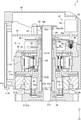
- FIG. 3 is a longitudinal cross-sectional view of a joint part shown in FIG. 1 .
- FIG. 4 is a block diagram for explaining an electrical connection relationship between a first joint part, a second joint part, a third joint part, a fourth joint part, a fifth joint part, and a sixth joint part shown in FIG. 1 .
- FIG. 1 is a front view of an industrial robot 1 according to an embodiment of the present invention.
- FIG. 2(A) is a perspective view of the industrial robot 1 shown in FIG. 1
- FIG. 2(B) is a perspective view showing a state in which the industrial robot 1 shown in FIG. 2(A) is operating.
- the industrial robot 1 (hereinafter referred to as a “robot 1 ”) of the present embodiment is an articulated robot used for assembling or producing a predetermined product and is used by being installed in an assembly line or a production line.
- the robot 1 includes a plurality of joint parts 2 and a plurality of arms 3 .
- the robot 1 includes six joint parts 2 and two arms 3 .
- the six joint parts 2 are distinguishably referred to, the six joint parts 2 are referred to as a “first joint part 2 A,” a “second joint part 2 B,” a “third joint part 2 C,” a “fourth joint part 2 D,” a “fifth joint part 2 E,” and a “sixth joint part 2 F.”
- first joint part 2 A a “first joint part 2 A”
- second joint part 2 B a “third joint part 2 C”
- a fourth joint part 2 D a “fifth joint part 2 E”
- a “sixth joint part 2 F a “sixth joint part 2 F.”
- two arms 3 are referred to as a “first arm 3 A” and a “second arm 3 B.”
- the robot 1 includes a support member 4 that is connected to the first joint part 2 A in a relatively rotatable manner.
- the support member 4 is formed in a cylindrical shape with a rim having a flange part 4 a , and a through-hole (not shown) that penetrates the support member 4 in an axial direction is formed on the inner circumferential side of the support member 4 .
- the flange part 4 a is formed in an annular shape and constitutes a bottom part of the robot 1 .
- the arm 3 is formed in an elongated cylindrical shape.
- the first joint part 2 A and the second joint part 2 B are connected in a relatively rotatable manner, and the second joint part 2 B and a base end of the first arm 3 A are fixed.
- a tip of the first arm 3 A and the third joint part 2 C are fixed
- the third joint part 2 C and the fourth joint part 2 D are connected in a relatively rotatable manner
- the fourth joint part 2 D and a base end of the second arm 3 B are connected in a relatively rotatable manner
- a tip of the second arm 3 B and the fifth joint part 2 E are fixed
- the fifth joint part 2 E and the sixth joint part 2 F are connected in a relatively rotatable manner.
- a hand, a tool, and the like can be attached to the sixth joint part 2 F in a relatively rotatable manner.
- the first joint part 2 A, the second joint part 2 B, and the third joint part 2 C are formed to have the same size, and the fourth joint part 2 D, the fifth joint part 2 E, and the sixth joint part 2 F are formed to have the same size.
- the sizes of the first joint part 2 A, the second joint part 2 B, and the third joint part 2 C are larger than the sizes of the fourth joint part 2 D, the fifth joint part 2 E and the sixth joint part 2 F.
- the first joint part 2 A, the second joint part 2 B, and the third joint part 2 C, the fourth joint part 2 D, the fifth joint part 2 E and the sixth joint part 2 F have the same configuration except for different sizes.
- FIG. 3 is a longitudinal cross-sectional view of the joint part 2 shown in FIG. 1 .
- FIG. 4 is a block diagram for explaining an electrical connection relationship between the first joint part 2 A, the second joint part 2 B, the third joint part 2 C, the fourth joint part 2 D, the fifth joint part 2 E, and the sixth joint part 2 F shown in FIG. 1 .
- the side in a Z 1 direction in FIG. 3 will be defined as the “upper” side and the side in a Z 2 direction which is the side opposite thereto will be defined as the “lower” side.
- the joint part 2 includes a motor 7 , a reduction gear 8 connected to the motor 7 , a position detection mechanism 9 configured to detect a rotational position of the motor 7 , a circuit board 10 to which the motor 7 and the position detection mechanism 9 are electrically connected, and a case 11 in which the motor 7 , the reduction gear 8 , the position detection mechanism 9 , and the circuit board 10 are housed.
- the motor 7 is a hollow motor in which a through-hole is formed at the center in a radial direction and has a hollow rotation shaft 13 .
- the motor 7 includes a rotor 14 and a stator 15 .
- the reduction gear 8 is a hollow reduction gear in which a through-hole is formed at the center in the radial direction.
- the motor 7 and the reduction gear 8 are disposed in an overlapping manner in the up-down direction. Specifically, the motor 7 is disposed on the upper side and the reduction gear 8 is disposed on the lower side. In addition, the motor 7 and the reduction gear 8 are disposed on the same axis.
- the reduction gear 8 of the present embodiment is a hollow wave gear device, and includes a rigid internal gear 16 , a flexible external gear 17 , a wave generation unit 18 , and a cross roller bearing 19 .
- the wave generation unit 18 includes a hollow input shaft 20 connected to the rotation shaft 13 and a wave bearing 21 attached to the outer circumferential side of the input shaft 20 .
- the rigid internal gear 16 serves as an output shaft of the reduction gear 8 .
- the joint part 2 includes a rotation restriction mechanism 25 that restricts rotation of the rotor 14 that is stopped, a cylindrical tubular member 26 inserted into the inner circumferential side of the rotation shaft 13 and the input shaft 20 , and an output-side member 27 fixed to the rigid internal gear 16 .
- the motor 7 includes the rotor 14 and the stator 15 .
- the rotor 14 includes the rotation shaft 13 and a driving magnet 29 fixed to the rotation shaft 13 .
- the rotation shaft 13 is formed in a substantially cylindrical shape elongated in the up-down direction and is disposed so that the axial direction of the rotation shaft 13 coincides with the up-down direction. That is, the up-down direction is the axial direction of the rotation shaft 13 and the axial direction of the rotor 14 .
- the driving magnet 29 is formed in a cylindrical shape. The length (length in the up-down direction) of the driving magnet 29 is shorter than the rotation shaft 13 , and the driving magnet 29 is fixed to the outer circumferential surface of the lower end side part of the rotation shaft 13 . In the present embodiment, the driving magnet 29 is fixed to the outer circumferential surface of the rotation shaft 13 so that the lower end surface of the rotation shaft 13 and the lower end surface of the driving magnet 29 are aligned.
- the stator 15 is formed in a substantially cylindrical shape as a whole, and is disposed on the outer circumferential side of the driving magnet 29 to cover the outer circumferential surface of the driving magnet 29 .
- the upper end side part of the rotation shaft 13 protrudes upward from the upper end surface of the stator 15 .
- the stator 15 includes a driving coil and a stator core having a plurality of salient poles around which a driving coil is wound via an insulator.
- the salient poles of the stator core are formed to protrude toward the inner circumferential side and a tip surface of the salient poles faces the outer circumferential surface of the driving magnet 29 .
- the motor 7 is fixed to the case 11 . Specifically, the outer circumferential surface of the stator 15 is fixed to the case 11 .
- the reduction gear 8 includes the rigid internal gear 16 , the flexible external gear 17 , the wave generation unit 18 , and the cross roller bearing 19 .
- the rigid internal gear 16 is formed in a flat and substantially cylindrical shape, and is disposed so that the axial direction of the rigid internal gear 16 and the up-down direction are aligned. That is, the up-down direction is the axial direction of the rigid internal gear 16 which is an output shaft of the reduction gear 8 .
- the rigid internal gear 16 is fixed to an inner ring 19 a of the cross roller bearing 19 .
- An outer ring 19 b of the cross roller bearing 19 is fixed to the lower end side part of the case 11 , and the rigid internal gear 16 is rotatably held by the lower end side part of the case 11 via the cross roller bearing 19 .
- the flexible external gear 17 is formed in a substantially tubular shape with a rim having a flange part 17 a at its upper end.
- the flange part 17 a is formed in a substantially annular shape and an outer circumferential side part of the flange part 17 a is fixed to the case 11 . That is, the reduction gear 8 is fixed to the case 11 .
- the rigid internal gear 16 constitutes a lower end side part of the reduction gear 8 .
- the flange part 17 a constitutes an upper end side part of the reduction gear 8 .
- Internal teeth are formed on the inner circumferential surface of the rigid internal gear 16 .
- On the outer circumferential surface on the lower end side of the flexible external gear 17 external teeth meshed with the internal teeth of the rigid internal gear 16 are formed.
- the wave generation unit 18 includes the input shaft 20 and the wave bearing 21 .
- the input shaft 20 is formed in a tubular shape elongated in the up-down direction as a whole and is disposed so that the axial direction of the input shaft 20 coincides with the up-down direction.
- a part other than the lower end side part of the input shaft 20 is formed in an elongated and substantially cylindrical shape.
- the lower end side part of the input shaft 20 becomes an elliptical part 20 a in which the shape of the inner circumferential surface when viewed in the axial direction of the input shaft 20 is a circular shape and the shape of the outer circumferential surface when viewed in the axial direction of the input shaft 20 is an elliptical shape.
- the upper end side part of the input shaft 20 is inserted into and fixed to the inner circumferential side of the lower end side part of the rotation shaft 13 .
- the upper end side part of the input shaft 20 is inserted and fixed to the inner circumferential side of a part of the rotation shaft 13 to which the driving magnet 29 is fixed.
- the rotation shaft 13 and the input shaft 20 are disposed on the same axis.
- the upper end side part of the input shaft 20 is fixed to the rotation shaft 13 by bonding.
- the central part of the input shaft 20 in the up-down direction is rotatably supported by a bearing 30 .
- the bearing 30 is a ball bearing.
- the bearing 30 is attached to a bearing holding member 31 , and the bearing holding member 31 is fixed to the case 11 . That is, the input shaft 20 is rotatably supported by the bearing 30 attached to the case 11 via the bearing holding member 31 .
- the bearing holding member 31 is formed in an annular and flat plate shape, and is fixed to the case 11 so that it overlaps the flange part 17 a of the flexible external gear 17 in the up-down direction.
- the wave bearing 21 is a ball bearing including a flexible inner ring and outer ring.
- the wave bearing 21 is disposed along the outer circumferential surface of the elliptical part 20 a and is bent elliptically.
- a lower end side part of the flexible external gear 17 in which external teeth are formed is disposed on the outer circumferential side of the wave bearing 21 to surround the wave bearing 21 , and this part is bent elliptically.
- the external teeth of the flexible external gear 17 are meshed with the internal teeth of the rigid internal gear 16 at two parts of the lower end side part of the flexible external gear 17 bent elliptically in the long axis direction.
- the output-side member 27 is formed in a substantially cylindrical shape with a rim including a flange part 27 a and a cylindrical part 27 b .
- the output-side member 27 is disposed so that the axial direction of the output-side member 27 coincides with the up-down direction, and a through-hole 27 c that penetrates in the up-down direction is formed on the inner circumferential side of the output-side member 27 .
- the flange part 27 a is formed in a flat plate and annular shape and is connected to the lower end of the cylindrical part 27 b .
- the flange part 27 a is fixed to the rigid internal gear 16 so that the upper surface of the flange part 27 a comes in contact with the lower surface of the rigid internal gear 16 .
- the flange part 27 a is disposed below the lower end of the case 11 and is disposed outside the case 11 .
- a small-diameter part 27 d having a smaller outer diameter than the lower end side part of the cylindrical part 27 b is formed on the upper end side of the cylindrical part 27 b .
- an annular stepped surface 27 e that is orthogonal to the up-down direction is formed on the outer circumferential side of the upper end side part of the cylindrical part 27 b .
- the small-diameter part 27 d is inserted into the inner circumferential side of the lower end side part of the tubular member 26 and the lower end surface of the tubular member 26 faces the stepped surface 27 e .
- the through-hole 27 c communicates with the inner circumferential side of the tubular member 26 .
- the upper end side part of the cylindrical part 27 b is disposed on the inner circumferential side of the lower end side part of the input shaft 20 .
- a bearing 34 is disposed between the outer circumferential surface of the cylindrical part 27 b and the inner circumferential surface of the lower end side part of the input shaft 20 .
- the bearing 34 is a ball bearing.
- the tubular member 26 is formed in a cylindrical shape elongated in the up-down direction and is disposed so that the axial direction of the tubular member 26 coincides with the up-down direction. As described above, the tubular member 26 is inserted into the inner circumferential side of the rotation shaft 13 and the input shaft 20 . The upper end surface of the tubular member 26 is disposed above the upper end surface of the rotation shaft 13 , and the lower end surface of the tubular member 26 is disposed above the lower end surface of the input shaft 20 .
- the small-diameter part 27 d of the output-side member 27 is inserted into the inner circumferential side of the lower end side part of the tubular member 26 , the lower end surface of the tubular member 26 faces the stepped surface 27 e , and the lower end side of the tubular member 26 is held by the output-side member 27 .
- the upper end side of the tubular member 26 is held by a holding member 32 .
- the holding member 32 is fixed to a support 33 , and the support 33 is fixed to the case 11 . That is, the holding member 32 is fixed to the case 11 via the support 33 .
- the holding member 32 includes a cylindrical holding part 32 a for holding the upper end side of the tubular member 26 .
- the holding part 32 a is disposed so that the axial direction of the holding part 32 a coincides with the up-down direction.
- a through-hole 32 b that penetrates in the up-down direction is formed on the inner circumferential side of the holding part 32 a .
- a large-diameter part 32 c having a larger inner diameter than the upper end side of the holding part 32 a is formed on the lower end side of the holding part 32 a .
- an annular stepped surface 32 d orthogonal to the up-down direction is formed on the inner circumferential side of the lower end side part of the holding part 32 a .
- the upper end side of the tubular member 26 is inserted into the inner circumferential side of the large-diameter part 32 c , and the upper end surface of the tubular member 26 faces the stepped surface 32 d .
- the through-hole 32 b communicates with the inner circumferential side of the tubular member 26 .
- the position detection mechanism 9 is disposed above the stator 15 .
- the position detection mechanism 9 includes a slit plate 36 fixed to the upper end side of the rotation shaft 13 and a sensor 37 .
- the sensor 37 is a transmission type optical sensor including a light emitting element and a light receiving element which are disposed to face each other.
- the sensor 37 is fixed to a support member 38 .
- the support member 38 is fixed to the case 11 . That is, the sensor 37 is fixed to the case 11 via the support member 38 .
- the slit plate 36 is formed into a thin flat plate shape and formed in an annular shape. In the slit plate 36 , a plurality of slit holes are formed at certain intervals in the circumferential direction of the slit plate 36 .
- the slit plate 36 is fixed to the rotation shaft 13 so that a part of the slit plate 36 in the circumferential direction is disposed between the light emitting element and the light receiving element of the sensor 37 .
- the case 11 includes a case main body 41 of which both upper and lower ends are open and a cover 42 that blocks an opening on the upper end side of the case main body 41 .
- An opening on the lower end side of the case main body 41 is blocked by the reduction gear 8 .
- On a side surface of the case main body 41 an opening 41 a that opens in a direction orthogonal to the up-down direction is formed. That is, in the case 11 , the opening 41 a that opens in a direction orthogonal to the up-down direction is formed.
- the opening 41 a is formed to penetrate through a side part of the case main body 41 .
- the rotation restriction mechanism 25 is housed in the case 11 .
- the rotation restriction mechanism 25 includes a flat plate-like and substantially annular rotation-side restricting member 45 fixed to the rotor 14 , a fixing-side restricting member 46 which is engaged with the rotation-side restricting member 45 and restricts movement of the rotation-side restricting member 45 in the circumferential direction of the rotor 14 , a drive mechanism 47 that moves the fixing-side restricting member 46 in the up-down direction, and a linear bushing 48 that guides the fixing-side restricting member 46 in the up-down direction.
- the drive mechanism 47 includes a compression coil spring 49 that biases the fixing-side restricting member 46 upward and a solenoid 50 that moves the fixing-side restricting member 46 downward.
- the fixing-side restricting member 46 is formed in a columnar shape with a rim having a flange part 46 a at its upper end, and is disposed so that the axial direction of the fixing-side restricting member 46 coincides with the up-down direction.
- the fixing-side restricting member 46 is fixed to a plunger 50 a of the solenoid 50 disposed on the upper side of the fixing-side restricting member 46 .
- On the lower end surface of the fixing-side restricting member 46 a concave part that is recessed toward the upper side is formed.
- An upper end side part of the compression coil spring 49 is disposed in the concave part.
- the linear bushing 48 is formed in a cylindrical shape with a rim having a flange part at its upper end and is disposed so that the axial direction of the linear bushing 48 coincides with the up-down direction.
- a part of the linear bushing 48 below the flange part is disposed in the concave part formed on the upper surface of the support member 38 .
- On a bottom of the concave part a recess in which the lower end side part of the compression coil spring 49 is disposed is formed to be recessed downward.
- a part of the fixing-side restricting member 46 below the flange part 46 a is disposed.
- the rotation-side restricting member 45 is fixed to the upper end surface of the rotation shaft 13 so that the thickness direction of the rotation-side restricting member 45 coincides with the up-down direction, and is disposed above the position detection mechanism 9 .
- On the rotation-side restricting member 45 a plurality of protrusions that protrude radially outward from the rotor 14 are formed at certain intervals in the circumferential direction of the rotor 14 .
- the fixing-side restricting member 46 When the solenoid 50 is not energized, the fixing-side restricting member 46 is raised by a biasing force of the compression coil spring 49 so that the flange part 46 a of the fixing-side restricting member 46 is disposed between protrusions of the rotation-side restricting member 45 in the circumferential direction of the rotor 14 . Therefore, rotation of the rotor 14 that is stopped is restricted according to the protrusion of the rotation-side restricting member 45 and the flange part 46 a .
- the solenoid 50 when the solenoid 50 is energized, as shown in FIG.
- the fixing-side restricting member 46 descends until the plunger 50 a protrudes downward and the flange part 46 a is disengaged from between protrusions of the rotation-side restricting member 45 in the circumferential direction of the rotor 14 . Therefore, the rotor 14 is rotatable.
- the circuit board 10 is a rigid board such as a glass epoxy board and is formed in a flat plate shape.
- the circuit board 10 is fixed to the case 11 so that the thickness direction of the circuit board 10 coincides with the up-down direction.
- the circuit board 10 is fixed to the upper end side of the case 11 and is disposed above the rotation-side restricting member 45 .
- the upper end of the tubular member 26 is disposed above the upper surface of the circuit board 10 .
- a motor driving circuit 58 configured to drive the motor 7 and a signal transmission circuit 59 configured to output a signal input to the circuit board 10 to the outside of the circuit board 10 are mounted.
- a signal transmission circuit 59 configured to output a signal input to the circuit board 10 to the outside of the circuit board 10 are mounted.
- connectors 61 and 62 to which an end of a wiring 60 is connected is mounted on the circuit board 10 .
- the connectors 61 and 62 are mounted on the upper surface of the circuit board 10 .
- the connectors 61 and 62 are a male type or female type connector, and when male type or female type connectors fixed to an end of the wiring 60 are engaged with the connectors 61 and 62 , an end of the wiring 60 is connected to the connectors 61 and 62 .
- the signal transmission circuit 59 is provided to output an output signal (specifically, an output signal from the sensor 37 ) from the position detection mechanism 9 or a signal obtained by processing the output signal on the circuit board 10 from the connector 61 or the connector 62 to the outside of the circuit board 10 .
- the signal transmission circuit 59 is provided to output a signal input from the connector 61 to the connector 62 and output a signal input from the connector 62 from the connector 61 .
- the support member 4 and the first joint part 2 A are connected in a relatively rotatable manner
- the first joint part 2 A and the second joint part 2 B are connected in a relatively rotatable manner
- the second joint part 2 B and a base end of the first arm 3 A are fixed
- a tip of the first arm 3 A and the third joint part 2 C are fixed
- the third joint part 2 C and the fourth joint part 2 D are connected in a relatively rotatable manner
- the fourth joint part 2 D and a base end of the second arm 3 B are connected in a relatively rotatable manner
- a tip of the second arm 3 B and the fifth joint part 2 E are fixed
- the fifth joint part 2 E and the sixth joint part 2 F are connected in a relatively rotatable manner.
- the joint parts 2 and the arms 3 are connected as described above so that the robot 1 can perform the operation shown in FIG. 2(B) .
- the axial direction of the rigid internal gear 16 of the first joint part 2 A will be defined as “the axial direction of the first joint part 2 A”
- the axial direction of the rigid internal gear 16 of the second joint part 2 B will be defined as “the axial direction of the second joint part 2 B”
- the axial direction of the rigid internal gear 16 of the third joint part 2 C will be defined as “the axial direction of the third joint part 2 C”
- the axial direction of the rigid internal gear 16 of the fourth joint part 2 D will be defined as “the axial direction of the fourth joint part 2 D”
- the axial direction of the rigid internal gear 16 of the fifth joint part 2 E will be defined as “the axial direction of the fifth joint part 2 E”
- the axial direction of the rigid internal gear 16 of the sixth joint part 2 F will be defined as “the axial direction of the sixth joint part 2 F.”
- the support member 4 and the first joint part 2 A are connected by fixing the support member 4 to the flange part 27 a of the first joint part 2 A.
- the support member 4 and the first joint part 2 A are connected when an end surface of the support member 4 on the side on which the flange part 4 a is not formed is fixed to the flange part 27 a of the first joint part 2 A. That is, the support member 4 and the first joint part 2 A are connected to each other so that the axial direction of the first joint part 2 A coincides with the axial direction of the support member 4 .
- the through-hole 27 c of the output-side member 27 of the first joint pad 2 A communicates with a through-hole of the support member 4 .
- the first joint part 2 A and the second joint part 2 B are connected so that the axial direction of the first joint part 2 A and the axial direction of the second joint part 2 B are perpendicular to each other.
- the case 11 of the first joint part 2 A is fixed to the flange part 27 a of the second joint part 2 B.
- a side surface on which the opening 41 a of the case main body 41 of the first joint part 2 A is formed is fixed to the flange part 27 a of the second joint part 2 B.
- the flange part 27 a of the second joint part 2 B blocks the opening 41 a of the case main body 41 of the first joint part 2 A, and the through-hole 27 c of the output-side member 27 of the second joint part 2 B communicates with the inside of the case 11 of the first joint part 2 A.
- the second joint part 2 B and the first arm 3 A are connected so that the axial direction of the second joint part 2 B and the longitudinal direction (axial direction) of the first arm 3 A are perpendicular to each other.
- a base end of the first arm 3 A is fixed to the case 11 of the second joint part 2 B.
- a base end of the first arm 3 A is fixed to a side surface on which the opening 41 a of the case main body 41 of the second joint part 2 B is formed.
- a base end of the first arm 3 A blocks the opening 41 a of the case main body 41 of the second joint part 2 B, and the inner circumferential side of the first arm 3 A communicates with the inside of the case 11 of the second joint part 2 B.
- the first arm 3 A and the third joint part 2 C are connected so that the longitudinal direction of the first arm 3 A and the axial direction of the third joint part 2 C are perpendicular to each other.
- a tip of the first arm 3 A is fixed to the case 11 of the third joint part 2 C.
- a tip of the first arm 3 A is fixed to a side surface on which the opening 41 a of the case main body 41 of the third joint part 2 C is formed.
- a tip of the first arm 3 A blocks the opening 41 a of the case main body 41 of the third joint part 2 C, and the inner circumferential side of the first arm 3 A communicates with the inside of the case 11 of the third joint part 2 C.
- the third joint part 2 C and the fourth joint part 2 D are connected so that the axial direction of the third joint part 2 C and the axial direction of the fourth joint part 2 D are perpendicular to each other.
- the case 11 of the fourth joint part 2 D is fixed to the flange part 27 a of the third joint part 2 C.
- a side surface on which the opening 41 a of the case main body 41 of the fourth joint part 2 D is formed is fixed to the flange part 27 a of the third joint part 2 C.
- a connecting member 63 fixed to a side surface on which the opening 41 a of the case main body 41 of the fourth joint part 2 D is formed a side surface on which the opening 41 a of the case main body 41 of the fourth joint part 2 D is formed is fixed to the flange part 27 a of the third joint part 2 C.
- the connecting member 63 is formed in a cylindrical shape with a rim having a flange part 63 a fixed to the flange part 27 a of the third joint part 2 C.
- the connecting member 63 blocks the opening 41 a of the case main body 41 of the fourth joint part 2 D, and a through-hole that penetrates in the axial direction of the connecting member 63 and the through-hole 27 c of the output-side member 27 of the third joint part 2 C communicate with the inside of the case 11 of the fourth joint part 2 D.
- the fourth joint part 2 D and the second arm 3 B are connected so that the axial direction of the fourth joint part 2 D and the longitudinal direction of the second arm 3 B coincide.
- a base end of the second arm 3 B is fixed to the flange part 27 a of the fourth joint part 2 D.
- the inner circumferential side of the second arm 3 B communicates with the through-hole 27 c of the output-side member 27 of the fourth joint part 2 D.
- a flange part 3 a for fixing a base end of the second arm 3 B to the flange part 27 a of the fourth joint part 2 D is formed, and the flange part 27 a of the fourth joint part 2 D and the flange part 3 a are fixed to each other.
- the second arm 3 B and the fifth joint part 2 E are connected so that the longitudinal direction of the second arm 3 B and the axial direction of the fifth joint part 2 E are perpendicular to each other.
- a tip of the second arm 3 B is fixed to the case 11 of the fifth joint part 2 E.
- a tip of the second arm 3 B is fixed to a side surface on which the opening 41 a of the case main body 41 of the fifth joint part 2 E is formed.
- a tip of the second arm 3 B blocks the opening 41 a of the case main body 41 of the fifth joint part 2 E, and the inner circumferential side of the second arm 3 B communicates with the inside of the case 11 of the fifth joint part 2 E.
- the fifth joint part 2 E and the sixth joint part 2 F are connected so that the axial direction of the fifth joint part 2 E and the axial direction of the sixth joint part 2 F are perpendicular to each other.
- the case 11 of the sixth joint part 2 F is fixed to the flange part 27 a of the fifth joint part 2 E.
- a side surface on which the opening 41 a of the case main body 41 of the sixth joint part 2 F is formed is fixed to the flange part 27 a of the fifth joint part 2 E.
- the flange part 27 a of the fifth joint part 2 E blocks the opening 41 a of the case main body 41 of the sixth joint part 2 F, and the through-hole 27 c of the output-side member 27 of the fifth joint part 2 E communicates with the inside of the case 11 of the sixth joint part 2 F.
- the circuit board 10 of the first joint part 2 A is referred to as a “circuit board 10 A”
- the circuit board 10 of the second joint part 2 B is referred to as a “circuit board 10 B”
- the circuit board 10 of the third joint part 2 C is referred to as a “circuit board 10 C”
- the circuit board 10 of the fourth joint part 2 D is referred to as a “circuit board 10 D”
- the circuit board 10 of the fifth joint part 2 E is referred to as a “circuit board 10 E”
- the circuit board 10 of the sixth joint part 2 F is referred to as a “circuit board 10 F.”
- the connector 61 of the circuit board 10 F of the sixth joint part 2 F and the connector 62 of the circuit board 10 E of the fifth joint part 2 E are connected by the wiring 60 . That is, one end of the wiring 60 drawn out from the case 11 of the sixth joint part 2 F is connected to the connector 61 of the circuit board 10 F and the other end thereof is connected to the connector 62 of the circuit board 10 E.
- the wiring 60 is drawn out from the case 11 of the sixth joint part 2 F through the opening 41 a of the sixth joint part 2 F, drawn through the through-hole 27 c of the output-side member 27 of the fifth joint part 2 E and the inner circumferential side of the tubular member 26 of the fifth joint part 2 E, and connected to the connector 62 of the circuit board 10 E.
- the connector 61 of the circuit board 10 E of the fifth joint part 2 E and the connector 62 of the circuit board 10 D of the fourth joint part 2 D are connected by the wiring 60 . That is, one end of the wiring 60 drawn out from the case 11 of the fifth joint part 2 E is connected to the connector 61 of the circuit board 10 E and the other end thereof is connected to the connector 62 of the circuit board 10 D.
- the wiring 60 is drawn out from the case 11 of the fifth joint part 2 E through the opening 41 a of the fifth joint part 2 E, and drawn through the inner circumferential side of the second arm 3 B, the through-hole 27 c of the output-side member 27 of the fourth joint part 2 D and the inner circumferential side of the tubular member 26 of the fourth joint part 2 D, and is connected to the connector 62 of the circuit board 10 D.
- the connector 61 of the circuit board 10 D of the fourth joint part 2 D and the connector 62 of the circuit board 10 C of the third joint part 2 C are connected by the wiring 60 . That is, one end of the wiring 60 drawn out from the case 11 of the fourth joint part 2 D is connected to the connector 61 of the circuit board 10 D and the other end thereof is connected to the connector 62 of the circuit board 10 C.
- the wiring 60 is drawn out from the case 11 of the fourth joint part 2 D through the opening 41 a of the fourth joint part 2 D, drawn through the through-hole of the connecting member 63 , the through-hole 27 c of the output-side member 27 of the third joint part 2 C, and the inner circumferential side of the tubular member 26 of the third joint part 2 C, and connected to the connector 62 of the circuit board 10 C.
- the connector 61 of the circuit board 10 C of the third joint part 2 C and the connector 62 of the circuit board 10 B of the second joint part 2 B are connected by the wiring 60 . That is, one end of the wiring 60 drawn out from the case 11 of the third joint part 2 C is connected to the connector 61 of the circuit board 10 C and the other end thereof is connected to the connector 62 of the circuit board 10 B.
- the wiring 60 is drawn out from the case 11 of the third joint part 2 C through the opening 41 a of the third joint part 2 C, drawn through the inner circumferential side of the first arm 3 A and the opening 41 a of the second joint part 2 B, and connected to the connector 62 of the circuit board 10 B.
- the connector 61 of the circuit board 10 B of the second joint part 2 B and the connector 62 of the circuit board 10 A of the first joint part 2 A are connected by the wiring 60 . That is, one end of the wiring 60 drawn out from the case 11 of the second joint part 2 B is connected to the connector 61 of the circuit board 10 B, and the other end thereof is connected to the connector 62 of the circuit board 10 A.
- the wiring 60 is drawn out from the case 11 of the second joint part 2 B through the inner circumferential side of the tubular member 26 of the second joint part 2 B and the through-hole 27 c of the output-side member 27 of the second joint part 2 B, drawn through the opening 41 a of the first joint part 2 A, and connected to the connector 62 of the circuit board 10 A.
- the connector 61 of the circuit board 10 A is connected to a controller 65 of the robot 1 via the wiring 60 .
- the wiring 60 is drawn out from the case 11 of the first joint part 2 A through the inner circumferential side of the tubular member 26 of the first joint part 2 A and the through-hole 27 c of the output-side member 27 of the first joint part 2 A, and is drawn through the through-hole of the support member 4 .
- the connector 62 of the circuit boards 10 B, 10 C, 10 D, and 10 E is a first connector
- the connector 61 of the circuit boards 10 B, 10 C, 10 D, and 10 E is a second connector.
- the joint part 2 includes the circuit board 10 to which the motor 7 and the position detection mechanism 9 are electrically connected, and the signal transmission circuit 59 configured to output a signal input to the circuit board 10 to the outside of the circuit board 10 and the connectors 61 and 62 are mounted on the circuit board 10 . Therefore, in the present embodiment, as described above, one end of the wiring 60 disposed between six joint parts 2 is connected to the connector 61 of the circuit board 10 of one joint part 2 and the other end of the wiring 60 is connected to the connector 62 of the circuit board 10 of the other joint part 2 , and thus signal communication between the six joint parts 2 and signal communication between the six joint parts 2 and the controller 65 become possible.
- one end of the wiring 60 disposed between the six joint parts 2 is connected to the connector 61 of the circuit board 10 of one joint part 2 and the other end of the wiring 60 is connected to the connector 62 of the circuit board 10 of the other joint part 2 , and thus drawing of the wiring 60 between the six joint parts 2 can be completed.
- the robot 1 includes a plurality of joint parts 2 , it is possible to simplify drawing of the wiring 60 .
- drawing of the wiring 60 can be simplified, assembling of the robot 1 becomes easier.
- the joint part 2 includes the motor 7 , the reduction gear 8 , the position detection mechanism 9 , the circuit board 10 , the case 11 , and the output-side member 27 , and the motor 7 and the reduction gear 8 are fixed to the case 11 .
- the motor driving circuit 58 , the signal transmission circuit 59 , and the connectors 61 and 62 are mounted on the circuit board 10 . Therefore, in the present embodiment, the joint parts 2 can be functionally integrated as a joint module. Thus, in the present embodiment, it is possible to easily change the number of joint parts 2 of the robot 1 .
- the number of joint parts 2 of the robot 1 can be changed from 6 to 5, and thus it is possible to easily change the number of joint parts 2 of the robot 1 .
- the output-side member 27 is fixed to the rigid internal gear 16 serving as an output shaft of the reduction gear 8 , and the flange part 27 a disposed outside the case 11 is formed on the output-side member 27 . Therefore, in the present embodiment, it is possible to increase the fixing strength between the joint parts 2 using the flange part 27 a.
- the case 11 of the first joint part 2 A is fixed to the flange part 27 a of the second joint part 2 B
- a base end of the first arm 3 A is fixed to the case 11 of the second joint part 2 B
- a tip of the first arm 3 A is fixed to the case 11 of the third joint part 2 C
- the case 11 of the fourth joint part 2 D is fixed to the flange part 27 a of the third joint part 2 C
- a base end of the second arm 3 B is fixed to the flange part 27 a of the fourth joint part 2 D
- a tip of the second arm 3 B is fixed to the case 11 of the fifth joint part 2 E
- the case 11 of the sixth joint part 2 F is fixed to the flange part 27 a of the fifth joint part 2 E.
- the case 11 of the second joint part 2 B may be fixed to the flange part 27 a of the first joint part 2 A
- a base end of the first arm 3 A may be fixed to the flange part 27 a of the second joint part 2 B
- a tip of the first arm 3 A may be fixed to the flange part 27 a of the third joint part 2 C
- the flange part 27 a of the fourth joint part 2 D may be fixed to the case 11 of the third joint part 2 C
- a base end of the second arm 3 B may be fixed to the case 11 of the fourth joint part 2 D
- a tip of the second arm 3 B may be fixed to the flange part 27 a of the fifth joint part 2 E
- the flange part 27 a of the sixth joint part 2 F may be fixed to the case 11 of the fifth joint part 2 E.
- the rigid internal gear 16 serves as an output shaft of the reduction gear 8
- the flexible external gear 17 may serve as an output shaft of the reduction gear 8
- the rigid internal gear 16 is fixed to the case 11 and the inner ring 19 a of the cross roller bearing 19
- the flexible external gear 17 is fixed to the outer ring 19 b of the cross roller bearing 19 and the flange part 27 a of the output-side member 27 .
- the reduction gear 8 is a hollow wave gear device, but the reduction gear 8 may be a hollow reduction gear other than the hollow wave gear device.
- the reduction gear 8 may be a reduction gear other than the hollow reduction gear.
- the motor 7 is a hollow motor, but the motor 7 may be a motor other than the hollow motor.
- the robot 1 includes six joint parts 2 , but the number of joint parts 2 included in the robot 1 may be 5 or less or 7 or more.
- the robot 1 includes two arms 3 , but the number of arms 3 included in the robot 1 may be 1 or 3 or more.
- the wiring 60 is drawn inside the joint part 2 and the arm 3 , but the wiring 60 may be drawn to the outside of the joint part 2 and the arm 3 .
- the flange part 27 a is formed on the output-side member 27 , but the flange part 27 a may not be formed on the output-side member 27 as long as the arm 3 and the case 11 can be fixed to the output-side member 27 .
- the robot 1 is an industrial robot, but the robot 1 can be applied for various applications.
- the robot 1 may be a service robot.
Applications Claiming Priority (4)
| Application Number | Priority Date | Filing Date | Title |
|---|---|---|---|
| JPJP2016-067517 | 2016-03-30 | ||
| JP2016-067517 | 2016-03-30 | ||
| JP2016067517A JP6708953B2 (ja) | 2016-03-30 | 2016-03-30 | ロボット |
| PCT/JP2017/009124 WO2017169576A1 (ja) | 2016-03-30 | 2017-03-08 | ロボット |
Publications (2)
| Publication Number | Publication Date |
|---|---|
| US20200298423A1 US20200298423A1 (en) | 2020-09-24 |
| US11224978B2 true US11224978B2 (en) | 2022-01-18 |
Family
ID=59964076
Family Applications (1)
| Application Number | Title | Priority Date | Filing Date |
|---|---|---|---|
| US16/089,388 Active 2038-08-13 US11224978B2 (en) | 2016-03-30 | 2017-03-08 | Robot |
Country Status (6)
| Country | Link |
|---|---|
| US (1) | US11224978B2 (ja) |
| JP (1) | JP6708953B2 (ja) |
| KR (1) | KR102123951B1 (ja) |
| CN (1) | CN108883540B (ja) |
| TW (1) | TWI706845B (ja) |
| WO (1) | WO2017169576A1 (ja) |
Families Citing this family (11)
| Publication number | Priority date | Publication date | Assignee | Title |
|---|---|---|---|---|
| WO2019096923A2 (en) | 2017-11-15 | 2019-05-23 | Universal Robots A/S | Strain wave gear with output flange and integrated encoder |
| JP7056455B2 (ja) * | 2018-08-07 | 2022-04-19 | 日本電産株式会社 | 多関節ロボット及びモータ |
| JP7241378B2 (ja) * | 2018-08-09 | 2023-03-17 | 東京ロボティクス株式会社 | ロボットアーム及びロボット |
| CN109176557A (zh) * | 2018-10-18 | 2019-01-11 | 刘山平 | 一种机器人 |
| CN109227562A (zh) * | 2018-10-18 | 2019-01-18 | 刘山平 | 一种工业机器人手臂组件 |
| JP7135815B2 (ja) * | 2018-12-10 | 2022-09-13 | 日本電産株式会社 | ロボット、及びロボットの製造方法 |
| JP7381204B2 (ja) | 2019-01-29 | 2023-11-15 | ファナック株式会社 | ロボット |
| CN110262168A (zh) * | 2019-07-01 | 2019-09-20 | 桂林飞宇科技股份有限公司 | 一种稳定器 |
| DK180930B1 (en) | 2021-03-25 | 2022-06-29 | Universal Robots As | Strain wave gear with encoder integration |
| TWI766798B (zh) * | 2021-08-31 | 2022-06-01 | 友達光電股份有限公司 | 關節裝置與關節模組 |
| CN114393594B (zh) * | 2022-01-28 | 2023-11-24 | 苏州灵猴机器人有限公司 | 一种机器人 |
Citations (9)
| Publication number | Priority date | Publication date | Assignee | Title |
|---|---|---|---|---|
| US5155423A (en) * | 1986-02-18 | 1992-10-13 | Robotics Research Corporation | Industrial robot with servo |
| US5293107A (en) * | 1993-02-24 | 1994-03-08 | Fanuc Robotics North America, Inc. | Motorized rotary joint and method of constructing a modular robot utilizing same |
| US6329731B1 (en) * | 1999-08-10 | 2001-12-11 | The Swatch Group Management Services Ag | Driving unit including a liquid cooled electric motor and a planetary gear |
| JP2004174704A (ja) | 2002-11-14 | 2004-06-24 | Sony Corp | アクチュエータ装置及び多軸型ロボット |
| WO2009034789A1 (ja) | 2007-09-11 | 2009-03-19 | Kabushiki Kaisha Yaskawa Denki | 内圧防爆構造のロボット |
| US7971504B2 (en) * | 2005-09-27 | 2011-07-05 | Kabushiki Kaisha Yaskawa Denki | Articulated manipulator |
| US8410732B2 (en) | 2006-03-03 | 2013-04-02 | Kristian Kassow | Programmable robot and user interface |
| WO2015004731A1 (ja) | 2013-07-09 | 2015-01-15 | 株式会社安川電機 | ロボットおよびロボットの関節機構 |
| JP2015085451A (ja) | 2013-10-31 | 2015-05-07 | セイコーエプソン株式会社 | ロボット |
Family Cites Families (4)
| Publication number | Priority date | Publication date | Assignee | Title |
|---|---|---|---|---|
| JP5690153B2 (ja) * | 2011-01-21 | 2015-03-25 | Ntn株式会社 | インホイールモータ駆動装置 |
| JP6150736B2 (ja) * | 2013-03-19 | 2017-06-21 | 株式会社ハーモニック・ドライブ・システムズ | 波動歯車装置および中空型回転アクチュエータ |
| US10050359B2 (en) * | 2013-10-31 | 2018-08-14 | Seiko Epson Corporation | Robot |
| JP6221882B2 (ja) * | 2014-03-25 | 2017-11-01 | 東芝ライテック株式会社 | 照明器具及び照明制御システム |
-
2016
- 2016-03-30 JP JP2016067517A patent/JP6708953B2/ja active Active
-
2017
- 2017-03-08 KR KR1020187028098A patent/KR102123951B1/ko active IP Right Grant
- 2017-03-08 US US16/089,388 patent/US11224978B2/en active Active
- 2017-03-08 CN CN201780020401.5A patent/CN108883540B/zh active Active
- 2017-03-08 WO PCT/JP2017/009124 patent/WO2017169576A1/ja active Application Filing
- 2017-03-17 TW TW106108867A patent/TWI706845B/zh active
Patent Citations (10)
| Publication number | Priority date | Publication date | Assignee | Title |
|---|---|---|---|---|
| US5155423A (en) * | 1986-02-18 | 1992-10-13 | Robotics Research Corporation | Industrial robot with servo |
| US5293107A (en) * | 1993-02-24 | 1994-03-08 | Fanuc Robotics North America, Inc. | Motorized rotary joint and method of constructing a modular robot utilizing same |
| US6329731B1 (en) * | 1999-08-10 | 2001-12-11 | The Swatch Group Management Services Ag | Driving unit including a liquid cooled electric motor and a planetary gear |
| JP2004174704A (ja) | 2002-11-14 | 2004-06-24 | Sony Corp | アクチュエータ装置及び多軸型ロボット |
| US7971504B2 (en) * | 2005-09-27 | 2011-07-05 | Kabushiki Kaisha Yaskawa Denki | Articulated manipulator |
| US8410732B2 (en) | 2006-03-03 | 2013-04-02 | Kristian Kassow | Programmable robot and user interface |
| US20130255426A1 (en) * | 2006-03-03 | 2013-10-03 | Universal Robots Aps | Programmable robot and user interface |
| WO2009034789A1 (ja) | 2007-09-11 | 2009-03-19 | Kabushiki Kaisha Yaskawa Denki | 内圧防爆構造のロボット |
| WO2015004731A1 (ja) | 2013-07-09 | 2015-01-15 | 株式会社安川電機 | ロボットおよびロボットの関節機構 |
| JP2015085451A (ja) | 2013-10-31 | 2015-05-07 | セイコーエプソン株式会社 | ロボット |
Non-Patent Citations (1)
| Title |
|---|
| "International Search Report (Form PCT/ISA/210)" of PCT/JP2017/009124, dated May 16, 2017, with English translation thereof, pp. 1-4. |
Also Published As
| Publication number | Publication date |
|---|---|
| JP2017177275A (ja) | 2017-10-05 |
| US20200298423A1 (en) | 2020-09-24 |
| KR102123951B1 (ko) | 2020-06-23 |
| TW201736064A (zh) | 2017-10-16 |
| WO2017169576A1 (ja) | 2017-10-05 |
| CN108883540A (zh) | 2018-11-23 |
| TWI706845B (zh) | 2020-10-11 |
| KR20180132658A (ko) | 2018-12-12 |
| JP6708953B2 (ja) | 2020-06-10 |
| CN108883540B (zh) | 2022-05-17 |
Similar Documents
| Publication | Publication Date | Title |
|---|---|---|
| US11224978B2 (en) | Robot | |
| US11027422B2 (en) | Rotary actuator and robot | |
| US11161255B2 (en) | Robot | |
| KR102374946B1 (ko) | 회전 액추에이터 및 로봇 | |
| WO2017169418A1 (ja) | 回転アクチュエータおよびロボット | |
| US20200298426A1 (en) | Rotary actuator and robot | |
| JP2019523408A (ja) | センサ装置 | |
| JP2020022318A (ja) | 回転アクチュエータ及びロボット | |
| WO2017169580A1 (ja) | 回転アクチュエータおよびロボット | |
| JP2020025429A (ja) | 回転アクチュエータ及びロボット | |
| JP2020022319A (ja) | 回転アクチュエータ及びロボット | |
| JP2019068682A (ja) | 導線部材および駆動ユニット | |
| US10608510B2 (en) | Power supply terminal structure and method for assembling motor | |
| KR101544936B1 (ko) | 전선 길이가 가변되는 회전형 커넥터 및 전기 접속 시스템 | |
| US20200157727A1 (en) | Actuator, clutch device, and washing machine | |
| JP6247626B2 (ja) | 駆動装置 |
Legal Events
| Date | Code | Title | Description |
|---|---|---|---|
| FEPP | Fee payment procedure |
Free format text: ENTITY STATUS SET TO UNDISCOUNTED (ORIGINAL EVENT CODE: BIG.); ENTITY STATUS OF PATENT OWNER: LARGE ENTITY |
|
| AS | Assignment |
Owner name: NIDEC CORPORATION, JAPAN Free format text: ASSIGNMENT OF ASSIGNORS INTEREST;ASSIGNOR:AYUZAWA, YUU;REEL/FRAME:047097/0488 Effective date: 20180912 |
|
| STPP | Information on status: patent application and granting procedure in general |
Free format text: NON FINAL ACTION MAILED |
|
| STPP | Information on status: patent application and granting procedure in general |
Free format text: RESPONSE TO NON-FINAL OFFICE ACTION ENTERED AND FORWARDED TO EXAMINER |
|
| STPP | Information on status: patent application and granting procedure in general |
Free format text: FINAL REJECTION MAILED |
|
| STPP | Information on status: patent application and granting procedure in general |
Free format text: DOCKETED NEW CASE - READY FOR EXAMINATION |
|
| STPP | Information on status: patent application and granting procedure in general |
Free format text: NOTICE OF ALLOWANCE MAILED -- APPLICATION RECEIVED IN OFFICE OF PUBLICATIONS |
|
| STPP | Information on status: patent application and granting procedure in general |
Free format text: PUBLICATIONS -- ISSUE FEE PAYMENT RECEIVED |
|
| STPP | Information on status: patent application and granting procedure in general |
Free format text: PUBLICATIONS -- ISSUE FEE PAYMENT VERIFIED |
|
| STCF | Information on status: patent grant |
Free format text: PATENTED CASE |