US11221060B2 - Transmission for a motor vehicle - Google Patents
Transmission for a motor vehicle Download PDFInfo
- Publication number
- US11221060B2 US11221060B2 US16/060,479 US201616060479A US11221060B2 US 11221060 B2 US11221060 B2 US 11221060B2 US 201616060479 A US201616060479 A US 201616060479A US 11221060 B2 US11221060 B2 US 11221060B2
- Authority
- US
- United States
- Prior art keywords
- shaft
- gear
- power transmission
- transmission
- input shaft
- Prior art date
- Legal status (The legal status is an assumption and is not a legal conclusion. Google has not performed a legal analysis and makes no representation as to the accuracy of the status listed.)
- Active, expires
Links
Images


Classifications
-
- F—MECHANICAL ENGINEERING; LIGHTING; HEATING; WEAPONS; BLASTING
- F16—ENGINEERING ELEMENTS AND UNITS; GENERAL MEASURES FOR PRODUCING AND MAINTAINING EFFECTIVE FUNCTIONING OF MACHINES OR INSTALLATIONS; THERMAL INSULATION IN GENERAL
- F16H—GEARING
- F16H3/00—Toothed gearings for conveying rotary motion with variable gear ratio or for reversing rotary motion
- F16H3/006—Toothed gearings for conveying rotary motion with variable gear ratio or for reversing rotary motion power being selectively transmitted by either one of the parallel flow paths
-
- B—PERFORMING OPERATIONS; TRANSPORTING
- B60—VEHICLES IN GENERAL
- B60K—ARRANGEMENT OR MOUNTING OF PROPULSION UNITS OR OF TRANSMISSIONS IN VEHICLES; ARRANGEMENT OR MOUNTING OF PLURAL DIVERSE PRIME-MOVERS IN VEHICLES; AUXILIARY DRIVES FOR VEHICLES; INSTRUMENTATION OR DASHBOARDS FOR VEHICLES; ARRANGEMENTS IN CONNECTION WITH COOLING, AIR INTAKE, GAS EXHAUST OR FUEL SUPPLY OF PROPULSION UNITS IN VEHICLES
- B60K6/00—Arrangement or mounting of plural diverse prime-movers for mutual or common propulsion, e.g. hybrid propulsion systems comprising electric motors and internal combustion engines ; Control systems therefor, i.e. systems controlling two or more prime movers, or controlling one of these prime movers and any of the transmission, drive or drive units Informative references: mechanical gearings with secondary electric drive F16H3/72; arrangements for handling mechanical energy structurally associated with the dynamo-electric machine H02K7/00; machines comprising structurally interrelated motor and generator parts H02K51/00; dynamo-electric machines not otherwise provided for in H02K see H02K99/00
- B60K6/20—Arrangement or mounting of plural diverse prime-movers for mutual or common propulsion, e.g. hybrid propulsion systems comprising electric motors and internal combustion engines ; Control systems therefor, i.e. systems controlling two or more prime movers, or controlling one of these prime movers and any of the transmission, drive or drive units Informative references: mechanical gearings with secondary electric drive F16H3/72; arrangements for handling mechanical energy structurally associated with the dynamo-electric machine H02K7/00; machines comprising structurally interrelated motor and generator parts H02K51/00; dynamo-electric machines not otherwise provided for in H02K see H02K99/00 the prime-movers consisting of electric motors and internal combustion engines, e.g. HEVs
- B60K6/22—Arrangement or mounting of plural diverse prime-movers for mutual or common propulsion, e.g. hybrid propulsion systems comprising electric motors and internal combustion engines ; Control systems therefor, i.e. systems controlling two or more prime movers, or controlling one of these prime movers and any of the transmission, drive or drive units Informative references: mechanical gearings with secondary electric drive F16H3/72; arrangements for handling mechanical energy structurally associated with the dynamo-electric machine H02K7/00; machines comprising structurally interrelated motor and generator parts H02K51/00; dynamo-electric machines not otherwise provided for in H02K see H02K99/00 the prime-movers consisting of electric motors and internal combustion engines, e.g. HEVs characterised by apparatus, components or means specially adapted for HEVs
- B60K6/36—Arrangement or mounting of plural diverse prime-movers for mutual or common propulsion, e.g. hybrid propulsion systems comprising electric motors and internal combustion engines ; Control systems therefor, i.e. systems controlling two or more prime movers, or controlling one of these prime movers and any of the transmission, drive or drive units Informative references: mechanical gearings with secondary electric drive F16H3/72; arrangements for handling mechanical energy structurally associated with the dynamo-electric machine H02K7/00; machines comprising structurally interrelated motor and generator parts H02K51/00; dynamo-electric machines not otherwise provided for in H02K see H02K99/00 the prime-movers consisting of electric motors and internal combustion engines, e.g. HEVs characterised by apparatus, components or means specially adapted for HEVs characterised by the transmission gearings
-
- B—PERFORMING OPERATIONS; TRANSPORTING
- B60—VEHICLES IN GENERAL
- B60K—ARRANGEMENT OR MOUNTING OF PROPULSION UNITS OR OF TRANSMISSIONS IN VEHICLES; ARRANGEMENT OR MOUNTING OF PLURAL DIVERSE PRIME-MOVERS IN VEHICLES; AUXILIARY DRIVES FOR VEHICLES; INSTRUMENTATION OR DASHBOARDS FOR VEHICLES; ARRANGEMENTS IN CONNECTION WITH COOLING, AIR INTAKE, GAS EXHAUST OR FUEL SUPPLY OF PROPULSION UNITS IN VEHICLES
- B60K6/00—Arrangement or mounting of plural diverse prime-movers for mutual or common propulsion, e.g. hybrid propulsion systems comprising electric motors and internal combustion engines ; Control systems therefor, i.e. systems controlling two or more prime movers, or controlling one of these prime movers and any of the transmission, drive or drive units Informative references: mechanical gearings with secondary electric drive F16H3/72; arrangements for handling mechanical energy structurally associated with the dynamo-electric machine H02K7/00; machines comprising structurally interrelated motor and generator parts H02K51/00; dynamo-electric machines not otherwise provided for in H02K see H02K99/00
- B60K6/20—Arrangement or mounting of plural diverse prime-movers for mutual or common propulsion, e.g. hybrid propulsion systems comprising electric motors and internal combustion engines ; Control systems therefor, i.e. systems controlling two or more prime movers, or controlling one of these prime movers and any of the transmission, drive or drive units Informative references: mechanical gearings with secondary electric drive F16H3/72; arrangements for handling mechanical energy structurally associated with the dynamo-electric machine H02K7/00; machines comprising structurally interrelated motor and generator parts H02K51/00; dynamo-electric machines not otherwise provided for in H02K see H02K99/00 the prime-movers consisting of electric motors and internal combustion engines, e.g. HEVs
- B60K6/42—Arrangement or mounting of plural diverse prime-movers for mutual or common propulsion, e.g. hybrid propulsion systems comprising electric motors and internal combustion engines ; Control systems therefor, i.e. systems controlling two or more prime movers, or controlling one of these prime movers and any of the transmission, drive or drive units Informative references: mechanical gearings with secondary electric drive F16H3/72; arrangements for handling mechanical energy structurally associated with the dynamo-electric machine H02K7/00; machines comprising structurally interrelated motor and generator parts H02K51/00; dynamo-electric machines not otherwise provided for in H02K see H02K99/00 the prime-movers consisting of electric motors and internal combustion engines, e.g. HEVs characterised by the architecture of the hybrid electric vehicle
- B60K6/48—Parallel type
-
- B—PERFORMING OPERATIONS; TRANSPORTING
- B60—VEHICLES IN GENERAL
- B60K—ARRANGEMENT OR MOUNTING OF PROPULSION UNITS OR OF TRANSMISSIONS IN VEHICLES; ARRANGEMENT OR MOUNTING OF PLURAL DIVERSE PRIME-MOVERS IN VEHICLES; AUXILIARY DRIVES FOR VEHICLES; INSTRUMENTATION OR DASHBOARDS FOR VEHICLES; ARRANGEMENTS IN CONNECTION WITH COOLING, AIR INTAKE, GAS EXHAUST OR FUEL SUPPLY OF PROPULSION UNITS IN VEHICLES
- B60K6/00—Arrangement or mounting of plural diverse prime-movers for mutual or common propulsion, e.g. hybrid propulsion systems comprising electric motors and internal combustion engines ; Control systems therefor, i.e. systems controlling two or more prime movers, or controlling one of these prime movers and any of the transmission, drive or drive units Informative references: mechanical gearings with secondary electric drive F16H3/72; arrangements for handling mechanical energy structurally associated with the dynamo-electric machine H02K7/00; machines comprising structurally interrelated motor and generator parts H02K51/00; dynamo-electric machines not otherwise provided for in H02K see H02K99/00
- B60K6/20—Arrangement or mounting of plural diverse prime-movers for mutual or common propulsion, e.g. hybrid propulsion systems comprising electric motors and internal combustion engines ; Control systems therefor, i.e. systems controlling two or more prime movers, or controlling one of these prime movers and any of the transmission, drive or drive units Informative references: mechanical gearings with secondary electric drive F16H3/72; arrangements for handling mechanical energy structurally associated with the dynamo-electric machine H02K7/00; machines comprising structurally interrelated motor and generator parts H02K51/00; dynamo-electric machines not otherwise provided for in H02K see H02K99/00 the prime-movers consisting of electric motors and internal combustion engines, e.g. HEVs
- B60K6/50—Architecture of the driveline characterised by arrangement or kind of transmission units
- B60K6/54—Transmission for changing ratio
- B60K6/547—Transmission for changing ratio the transmission being a stepped gearing
-
- F—MECHANICAL ENGINEERING; LIGHTING; HEATING; WEAPONS; BLASTING
- F16—ENGINEERING ELEMENTS AND UNITS; GENERAL MEASURES FOR PRODUCING AND MAINTAINING EFFECTIVE FUNCTIONING OF MACHINES OR INSTALLATIONS; THERMAL INSULATION IN GENERAL
- F16H—GEARING
- F16H3/00—Toothed gearings for conveying rotary motion with variable gear ratio or for reversing rotary motion
- F16H3/02—Toothed gearings for conveying rotary motion with variable gear ratio or for reversing rotary motion without gears having orbital motion
- F16H3/08—Toothed gearings for conveying rotary motion with variable gear ratio or for reversing rotary motion without gears having orbital motion exclusively or essentially with continuously meshing gears, that can be disengaged from their shafts
- F16H3/087—Toothed gearings for conveying rotary motion with variable gear ratio or for reversing rotary motion without gears having orbital motion exclusively or essentially with continuously meshing gears, that can be disengaged from their shafts characterised by the disposition of the gears
- F16H3/093—Toothed gearings for conveying rotary motion with variable gear ratio or for reversing rotary motion without gears having orbital motion exclusively or essentially with continuously meshing gears, that can be disengaged from their shafts characterised by the disposition of the gears with two or more countershafts
-
- B—PERFORMING OPERATIONS; TRANSPORTING
- B60—VEHICLES IN GENERAL
- B60K—ARRANGEMENT OR MOUNTING OF PROPULSION UNITS OR OF TRANSMISSIONS IN VEHICLES; ARRANGEMENT OR MOUNTING OF PLURAL DIVERSE PRIME-MOVERS IN VEHICLES; AUXILIARY DRIVES FOR VEHICLES; INSTRUMENTATION OR DASHBOARDS FOR VEHICLES; ARRANGEMENTS IN CONNECTION WITH COOLING, AIR INTAKE, GAS EXHAUST OR FUEL SUPPLY OF PROPULSION UNITS IN VEHICLES
- B60K6/00—Arrangement or mounting of plural diverse prime-movers for mutual or common propulsion, e.g. hybrid propulsion systems comprising electric motors and internal combustion engines ; Control systems therefor, i.e. systems controlling two or more prime movers, or controlling one of these prime movers and any of the transmission, drive or drive units Informative references: mechanical gearings with secondary electric drive F16H3/72; arrangements for handling mechanical energy structurally associated with the dynamo-electric machine H02K7/00; machines comprising structurally interrelated motor and generator parts H02K51/00; dynamo-electric machines not otherwise provided for in H02K see H02K99/00
- B60K6/20—Arrangement or mounting of plural diverse prime-movers for mutual or common propulsion, e.g. hybrid propulsion systems comprising electric motors and internal combustion engines ; Control systems therefor, i.e. systems controlling two or more prime movers, or controlling one of these prime movers and any of the transmission, drive or drive units Informative references: mechanical gearings with secondary electric drive F16H3/72; arrangements for handling mechanical energy structurally associated with the dynamo-electric machine H02K7/00; machines comprising structurally interrelated motor and generator parts H02K51/00; dynamo-electric machines not otherwise provided for in H02K see H02K99/00 the prime-movers consisting of electric motors and internal combustion engines, e.g. HEVs
- B60K6/42—Arrangement or mounting of plural diverse prime-movers for mutual or common propulsion, e.g. hybrid propulsion systems comprising electric motors and internal combustion engines ; Control systems therefor, i.e. systems controlling two or more prime movers, or controlling one of these prime movers and any of the transmission, drive or drive units Informative references: mechanical gearings with secondary electric drive F16H3/72; arrangements for handling mechanical energy structurally associated with the dynamo-electric machine H02K7/00; machines comprising structurally interrelated motor and generator parts H02K51/00; dynamo-electric machines not otherwise provided for in H02K see H02K99/00 the prime-movers consisting of electric motors and internal combustion engines, e.g. HEVs characterised by the architecture of the hybrid electric vehicle
- B60K6/48—Parallel type
- B60K2006/4816—Electric machine connected or connectable to gearbox internal shaft
-
- B—PERFORMING OPERATIONS; TRANSPORTING
- B60—VEHICLES IN GENERAL
- B60K—ARRANGEMENT OR MOUNTING OF PROPULSION UNITS OR OF TRANSMISSIONS IN VEHICLES; ARRANGEMENT OR MOUNTING OF PLURAL DIVERSE PRIME-MOVERS IN VEHICLES; AUXILIARY DRIVES FOR VEHICLES; INSTRUMENTATION OR DASHBOARDS FOR VEHICLES; ARRANGEMENTS IN CONNECTION WITH COOLING, AIR INTAKE, GAS EXHAUST OR FUEL SUPPLY OF PROPULSION UNITS IN VEHICLES
- B60K6/00—Arrangement or mounting of plural diverse prime-movers for mutual or common propulsion, e.g. hybrid propulsion systems comprising electric motors and internal combustion engines ; Control systems therefor, i.e. systems controlling two or more prime movers, or controlling one of these prime movers and any of the transmission, drive or drive units Informative references: mechanical gearings with secondary electric drive F16H3/72; arrangements for handling mechanical energy structurally associated with the dynamo-electric machine H02K7/00; machines comprising structurally interrelated motor and generator parts H02K51/00; dynamo-electric machines not otherwise provided for in H02K see H02K99/00
- B60K6/20—Arrangement or mounting of plural diverse prime-movers for mutual or common propulsion, e.g. hybrid propulsion systems comprising electric motors and internal combustion engines ; Control systems therefor, i.e. systems controlling two or more prime movers, or controlling one of these prime movers and any of the transmission, drive or drive units Informative references: mechanical gearings with secondary electric drive F16H3/72; arrangements for handling mechanical energy structurally associated with the dynamo-electric machine H02K7/00; machines comprising structurally interrelated motor and generator parts H02K51/00; dynamo-electric machines not otherwise provided for in H02K see H02K99/00 the prime-movers consisting of electric motors and internal combustion engines, e.g. HEVs
- B60K6/42—Arrangement or mounting of plural diverse prime-movers for mutual or common propulsion, e.g. hybrid propulsion systems comprising electric motors and internal combustion engines ; Control systems therefor, i.e. systems controlling two or more prime movers, or controlling one of these prime movers and any of the transmission, drive or drive units Informative references: mechanical gearings with secondary electric drive F16H3/72; arrangements for handling mechanical energy structurally associated with the dynamo-electric machine H02K7/00; machines comprising structurally interrelated motor and generator parts H02K51/00; dynamo-electric machines not otherwise provided for in H02K see H02K99/00 the prime-movers consisting of electric motors and internal combustion engines, e.g. HEVs characterised by the architecture of the hybrid electric vehicle
- B60K6/48—Parallel type
- B60K2006/4825—Electric machine connected or connectable to gearbox input shaft
-
- B—PERFORMING OPERATIONS; TRANSPORTING
- B60—VEHICLES IN GENERAL
- B60K—ARRANGEMENT OR MOUNTING OF PROPULSION UNITS OR OF TRANSMISSIONS IN VEHICLES; ARRANGEMENT OR MOUNTING OF PLURAL DIVERSE PRIME-MOVERS IN VEHICLES; AUXILIARY DRIVES FOR VEHICLES; INSTRUMENTATION OR DASHBOARDS FOR VEHICLES; ARRANGEMENTS IN CONNECTION WITH COOLING, AIR INTAKE, GAS EXHAUST OR FUEL SUPPLY OF PROPULSION UNITS IN VEHICLES
- B60K6/00—Arrangement or mounting of plural diverse prime-movers for mutual or common propulsion, e.g. hybrid propulsion systems comprising electric motors and internal combustion engines ; Control systems therefor, i.e. systems controlling two or more prime movers, or controlling one of these prime movers and any of the transmission, drive or drive units Informative references: mechanical gearings with secondary electric drive F16H3/72; arrangements for handling mechanical energy structurally associated with the dynamo-electric machine H02K7/00; machines comprising structurally interrelated motor and generator parts H02K51/00; dynamo-electric machines not otherwise provided for in H02K see H02K99/00
- B60K6/20—Arrangement or mounting of plural diverse prime-movers for mutual or common propulsion, e.g. hybrid propulsion systems comprising electric motors and internal combustion engines ; Control systems therefor, i.e. systems controlling two or more prime movers, or controlling one of these prime movers and any of the transmission, drive or drive units Informative references: mechanical gearings with secondary electric drive F16H3/72; arrangements for handling mechanical energy structurally associated with the dynamo-electric machine H02K7/00; machines comprising structurally interrelated motor and generator parts H02K51/00; dynamo-electric machines not otherwise provided for in H02K see H02K99/00 the prime-movers consisting of electric motors and internal combustion engines, e.g. HEVs
- B60K6/50—Architecture of the driveline characterised by arrangement or kind of transmission units
- B60K6/54—Transmission for changing ratio
- B60K2006/541—Transmission for changing ratio without reverse ratio using instead electric reversing
-
- F—MECHANICAL ENGINEERING; LIGHTING; HEATING; WEAPONS; BLASTING
- F16—ENGINEERING ELEMENTS AND UNITS; GENERAL MEASURES FOR PRODUCING AND MAINTAINING EFFECTIVE FUNCTIONING OF MACHINES OR INSTALLATIONS; THERMAL INSULATION IN GENERAL
- F16H—GEARING
- F16H3/00—Toothed gearings for conveying rotary motion with variable gear ratio or for reversing rotary motion
- F16H3/02—Toothed gearings for conveying rotary motion with variable gear ratio or for reversing rotary motion without gears having orbital motion
- F16H3/08—Toothed gearings for conveying rotary motion with variable gear ratio or for reversing rotary motion without gears having orbital motion exclusively or essentially with continuously meshing gears, that can be disengaged from their shafts
- F16H2003/0807—Toothed gearings for conveying rotary motion with variable gear ratio or for reversing rotary motion without gears having orbital motion exclusively or essentially with continuously meshing gears, that can be disengaged from their shafts with gear ratios in which the power is transferred by axially coupling idle gears
-
- F—MECHANICAL ENGINEERING; LIGHTING; HEATING; WEAPONS; BLASTING
- F16—ENGINEERING ELEMENTS AND UNITS; GENERAL MEASURES FOR PRODUCING AND MAINTAINING EFFECTIVE FUNCTIONING OF MACHINES OR INSTALLATIONS; THERMAL INSULATION IN GENERAL
- F16H—GEARING
- F16H3/00—Toothed gearings for conveying rotary motion with variable gear ratio or for reversing rotary motion
- F16H3/02—Toothed gearings for conveying rotary motion with variable gear ratio or for reversing rotary motion without gears having orbital motion
- F16H3/08—Toothed gearings for conveying rotary motion with variable gear ratio or for reversing rotary motion without gears having orbital motion exclusively or essentially with continuously meshing gears, that can be disengaged from their shafts
- F16H3/087—Toothed gearings for conveying rotary motion with variable gear ratio or for reversing rotary motion without gears having orbital motion exclusively or essentially with continuously meshing gears, that can be disengaged from their shafts characterised by the disposition of the gears
- F16H3/093—Toothed gearings for conveying rotary motion with variable gear ratio or for reversing rotary motion without gears having orbital motion exclusively or essentially with continuously meshing gears, that can be disengaged from their shafts characterised by the disposition of the gears with two or more countershafts
- F16H2003/0931—Toothed gearings for conveying rotary motion with variable gear ratio or for reversing rotary motion without gears having orbital motion exclusively or essentially with continuously meshing gears, that can be disengaged from their shafts characterised by the disposition of the gears with two or more countershafts each countershaft having an output gear meshing with a single common gear on the output shaft
-
- F—MECHANICAL ENGINEERING; LIGHTING; HEATING; WEAPONS; BLASTING
- F16—ENGINEERING ELEMENTS AND UNITS; GENERAL MEASURES FOR PRODUCING AND MAINTAINING EFFECTIVE FUNCTIONING OF MACHINES OR INSTALLATIONS; THERMAL INSULATION IN GENERAL
- F16H—GEARING
- F16H2200/00—Transmissions for multiple ratios
- F16H2200/003—Transmissions for multiple ratios characterised by the number of forward speeds
- F16H2200/0043—Transmissions for multiple ratios characterised by the number of forward speeds the gear ratios comprising four forward speeds
-
- F—MECHANICAL ENGINEERING; LIGHTING; HEATING; WEAPONS; BLASTING
- F16—ENGINEERING ELEMENTS AND UNITS; GENERAL MEASURES FOR PRODUCING AND MAINTAINING EFFECTIVE FUNCTIONING OF MACHINES OR INSTALLATIONS; THERMAL INSULATION IN GENERAL
- F16H—GEARING
- F16H2200/00—Transmissions for multiple ratios
- F16H2200/003—Transmissions for multiple ratios characterised by the number of forward speeds
- F16H2200/0047—Transmissions for multiple ratios characterised by the number of forward speeds the gear ratios comprising five forward speeds
-
- F—MECHANICAL ENGINEERING; LIGHTING; HEATING; WEAPONS; BLASTING
- F16—ENGINEERING ELEMENTS AND UNITS; GENERAL MEASURES FOR PRODUCING AND MAINTAINING EFFECTIVE FUNCTIONING OF MACHINES OR INSTALLATIONS; THERMAL INSULATION IN GENERAL
- F16H—GEARING
- F16H2200/00—Transmissions for multiple ratios
- F16H2200/003—Transmissions for multiple ratios characterised by the number of forward speeds
- F16H2200/0052—Transmissions for multiple ratios characterised by the number of forward speeds the gear ratios comprising six forward speeds
-
- Y—GENERAL TAGGING OF NEW TECHNOLOGICAL DEVELOPMENTS; GENERAL TAGGING OF CROSS-SECTIONAL TECHNOLOGIES SPANNING OVER SEVERAL SECTIONS OF THE IPC; TECHNICAL SUBJECTS COVERED BY FORMER USPC CROSS-REFERENCE ART COLLECTIONS [XRACs] AND DIGESTS
- Y02—TECHNOLOGIES OR APPLICATIONS FOR MITIGATION OR ADAPTATION AGAINST CLIMATE CHANGE
- Y02T—CLIMATE CHANGE MITIGATION TECHNOLOGIES RELATED TO TRANSPORTATION
- Y02T10/00—Road transport of goods or passengers
- Y02T10/60—Other road transportation technologies with climate change mitigation effect
- Y02T10/62—Hybrid vehicles
Definitions
- the invention relates generally to a transmission for a motor vehicle, including at least one input shaft which can be connected to an internal combustion engine in a rotationally fixed manner and includes at least one input shaft power transmission element, a first shaft including at least one power transmission element, a second shaft including at least one other power transmission element, and a transmission output shaft which is engaged with the first shaft and the second shaft, wherein the transmission includes at least one gear plane, in which the at least one input shaft power transmission element is engaged with the at least one power transmission element and with the at least one other power transmission element.
- the invention also relates generally to a hybrid drive including such a transmission and to a motor vehicle including the transmission or the hybrid drive.
- Example aspects of the invention provide a transmission for a motor vehicle, which has a small size, and therefore the transmission can be installed in small vehicles having little available installation space.
- a transmission of the type described above includes at most two, in particular precisely, two gear planes, and the one power transmission element and the other power transmission element are each designed as an idler gear.
- the transmission can be installed in small vehicles.
- the transmission can be installed in front-transverse vehicles having little axial installation space.
- a first input shaft power transmission element in a first gear plane, is engaged with a first idler gear and with yet another first idler gear.
- a second input power transmission element in a second gear plane, is engaged with a second idler gear and with yet another second idler gear.
- the input shaft power transmission element in particular the first and the second input shaft power transmission elements, can be a fixed gear.
- the gear plane corresponds to a plane of action, in which the input shaft power transmission element, the idler gear, and the other idler gear are engaged.
- the input shaft power transmission element, the idler gear, and the other idler gear can be engaged in a gear plane, independently of whether the axes of rotation of the input shaft power transmission element, the idler gear, and the other idler gear extend in parallel to each other or crosswise with respect to each other.
- An idler gear is a gear, for example a gearwheel, which is associated with a shaft, but is not connected to the shaft in a rotationally fixed manner. This means, the shaft can rotate relative to the idler gear.
- a rotationally fixed connection between the idler gear and the shaft can take place by an engagement device which, in one position, implements a rotationally fixed connection between the idler gear and the shaft.
- a power transmission element designed as a fixed gear is connected to the input shaft in a rotationally fixed manner. This means, an engagement device is not required for the rotationally fixed connection of the fixed gear to the input shaft.
- a rotationally fixed connection is understood to be a connection between two components, which is formed in such a way that the two components to be connected to each other always have the same rotationally speed. This is possible only when an engagement device is not arranged between the two interconnected components; otherwise, in the disengaged condition of the engagement device, the rotational speeds of the two components can differ from each other.
- a connection between two components is referred to as “connectable in a rotationally fixed manner” within the meaning of the invention when an engagement device is arranged between the two components to be connected to each other.
- a first input shaft of the at least one input shaft can be a hollow shaft.
- a second input shaft of the at least one input shaft can be a solid shaft.
- the first input power transmission element in the first gear plane, can be connected to the hollow shaft in a rotationally fixed manner and/or, in the second gear plane, the second input shaft power transmission element can be connected to the solid shaft in a rotationally fixed manner.
- the hollow shaft and the solid shaft can be arranged coaxially to each other, wherein the solid shaft can be partially enclosed by the hollow shaft.
- the transmission can include at least three, in particular precisely three or precisely four engagement devices.
- a first engagement device can be arranged in such a way that, in an engaged position, the first other idler gear is connected to the second shaft in a rotationally fixed manner.
- the first engagement device can be designed as a single shift element. This means, the first engagement device includes a first shift element, wherein, in an engaged position of the first shift element, the first other idler gear is connected to the second shaft in a rotationally fixed manner.
- a second engagement device can be arranged in such a way that, in an engaged position, a first single component of the first gear plane is connected to a second single component of the second gear plane in a rotationally fixed manner.
- the first single component can be the first idler gear or the first other idler gear.
- the second single component can be the second idler gear or the second other idler gear.
- the rotationally fixed connection of the first single component of the first gear plane to the second single component of the second gear plane can take place in such a way that the first single component of the first gear plane and the second single component of the second gear plane are not connected to the first shaft or to the second shaft in a rotationally fixed manner.
- the second engagement device can be advantageously designed in such a way that, in an engaged first position, the second other idler gear is connected to the second shaft in a rotationally fixed manner and, in an engaged second position, the second other idler gear is connected to the first other idler gear in a rotationally fixed manner.
- the second engagement device can be designed as a double shift element. This means, the second engagement device includes a second and a third shift element, wherein, in an engaged position of the second shift element, the second other idler gear is connected to the second shaft in a rotationally fixed manner and, in an engaged position of the third shift element, the second other idler gear is connected to the first other idler gear in a rotationally fixed manner.
- the transmission can include a third engagement device.
- the third engagement device can be arranged in such a way that the input shaft can be connected to the internal combustion engine in a rotationally fixed manner by the third engagement device.
- the hollow shaft in an engaged first position of the third engagement device, can be connected to the internal combustion engine in a rotationally fixed manner by the third engagement device.
- the solid shaft in an engaged second position of the third engagement device, can be connected to the internal combustion engine in a rotationally fixed manner.
- the third engagement device can be designed as a double shift element, in particular as a dual clutch, and can include a fourth and a fifth shift element.
- the provision of the dual clutch offers the advantage, in turn, that the axial length of the transmission can be reduced.
- the hollow shaft or the solid shaft can be connected to the internal combustion engine in a rotationally fixed manner by the fourth shift element.
- the solid shaft or the hollow shaft can be connected to the internal combustion engine in a rotationally fixed manner by the fifth shift element.
- a fourth engagement device can be present and can be arranged in such a way that, in a first engaged position, the first idler gear is connected to the first shaft in a rotationally fixed manner and, in a second engaged position, the second idler gear is connected to the first shaft in a rotationally fixed manner.
- the engagement device can include a sixth and a seventh shift element. In an engaged position of the sixth shift element, the first idler gear is connected to the first shaft in a rotationally fixed manner. In an engaged position of the seventh shift element, the second idler gear is connected to the first shaft in a rotationally fixed manner.
- the fourth engagement device can be designed as a double shift element.
- the engagement device includes an engagement means, via which the sixth or the seventh shift element can be engaged.
- the engagement means can be designed in such a way that, upon engagement of one shift element, the other shift element remains disengaged.
- the fourth engagement device can include two single shift elements, each of which can be engaged via a separate engagement means.
- At least one shift element can be designed as a shift element operating in a form-fit manner.
- the shift element can be designed as a shifting dog.
- at least one shift element can be designed as a shift element operating in a friction-locking manner.
- at least one shift element can be a shift element designed as a synchronizer.
- the same idler gear in particular the first idler gear and/or the second idler gear
- the same other idler gear in particular the first other idler gear and/or the second other idler gear
- the transmission can include a connecting means, via which an electric machine can be coupled to the transmission in a rotationally fixed manner.
- the electric machine can be an electric motor.
- the transmission can include a drive shaft which is connected to the third engagement device in a rotationally fixed manner. The drive shaft can therefore be connected to the at least one input shaft in a rotationally fixed manner by the third engagement device.
- the provision of the electric machine offers the advantage that a purely electric reverse operation is possible and, therefore, a mechanical reverse gear does not need to be provided, thereby simplifying the design of the multi-stage transmission.
- a direction of rotation of the electric machine, in particular a rotor of the electric machine, in a reverse gear can be opposite the direction of rotation of the electric machine in the forward gear. This means, in a forward operation of the transmission, the electric machine rotates in another direction than in a reverse operation of the transmission.
- the connecting means can be connected to the input shaft in a rotationally fixed manner.
- the connecting means can be connected to the third engagement device or to the hollow shaft in a rotationally fixed manner.
- the connection of the connecting means to the hollow shaft offers the advantage that a starting operation by the electric machine is possible without the need to engage the third engagement device.
- the electric machine can be detachably coupled to the transmission by the connecting means.
- the electric machine can be directly or indirectly coupled or couplable to the connecting means.
- the electric machine is coupled or couplable to the connecting means via a pre-reduction gear. It is particularly advantageous when the pre-reduction gear is designed in such a way that the electric machine can be operated at higher rotational speeds, and therefore the torque which the electric machine must output is lower.
- the electric machine is arranged in a housing, in particular in the housing of the transmission.
- the electric machine can be advantageously arranged coaxially to the further input shaft.
- the electric machine is arranged axially parallel to the further input shaft and is drivingly coupled, for example, via a traction mechanism drive or spur gearing and/or a bevel gear drive.
- the transmission can include yet another power transmission element which is engaged with the input power transmission element and with the idler gear and/or with the other idler gear.
- the further power transmission element can be arranged in such a way that it is engaged with the first input power transmission element and with the first idler gear or with the first other idler gear.
- the further power transmission element can be arranged between the input shaft power transmission element, in particular the first input shaft power transmission element, and the idler gear, in particular the first idler gear, or the other idler gear, in particular the first other idler gear.
- the transmission can be designed in such a way that a purely electric forward operation and a purely electric reverse operation can be implemented using the same gear.
- a purely electric reverse operation and a purely electric forward operation can be implemented via a second gear.
- the transmission can include at least one, in particular precisely one forward gear for a purely electric forward operation.
- the transmission can include at least one, in particular precisely one reverse gear for a purely electric or a purely internal combustion engine-driven reverse operation.
- the transmission can include at least four, in particular precisely four or precisely five forward gears for a forward operation with an internal combustion engine or for a forward operation with an internal combustion engine and an electric machine.
- the purely electric forward operation or reverse operation can take place by exclusively utilizing the electric machine. In the end, a transmission is obtained, with the aid of which a purely electric operation, a purely internal combustion engine-driven operation, or a hybrid operation can be implemented in a large speed range.
- a purely electric forward operation or a purely electric reverse operation can be implemented by engaging the first shift element, wherein the remaining shift elements are disengaged.
- a purely electric forward operation or a purely electric reverse operation can be implemented by engaging the first shift element and by engaging the fourth and/or fifth shift element, wherein the remaining shift elements are disengaged.
- An engagement of the internal combustion engine can take place when the first shift element and the fourth shift element are engaged, wherein the remaining shift elements are disengaged.
- the ratios of the transmission are designed in such a way that, in a forward operation, an engagement of the internal combustion engine takes place at 10 km/h to 15 km/h, which corresponds to a ratio of a second forward gear.
- a reversing operation of the transmission i.e., a repeated, in particular, switching between a forward operation and a reverse operation
- a reversing operation is advantageous, in particular, when the vehicle is stuck in snow, for example.
- the vehicle is to be rocked free from the stuck position.
- a change-over from the forward operation to the reverse operation or vice versa can be implemented by actuating the fourth and the fifth shift elements. “Actuating” is understood to be a disengagement or an engagement of the shift element.
- the sixth and/or the seventh shift element can be engaged, wherein the remaining shift elements are disengaged.
- the reversing operation can therefore be implemented by exclusively actuating the two shift elements of the dual clutch.
- the sixth and/or the seventh shift element can be engaged only during the initial engagement of the forward gear or reverse gear and can remain engaged and/or is or are not actuated in the reversing operation.
- the first shaft includes a first output gear and the second shaft includes a second output gear, wherein the first and the second output gears are connected to the transmission output shaft in a rotationally fixed manner.
- the gear planes can be arranged, as viewed axially, in the direction of power flow, on the input side in the traction operation of the internal combustion engine coupled to the input shaft, in the sequence: first gear plane and second gear plane.
- the perspective therefore originates from the input side, in particular from the internal combustion engine and the transmission coupled to the internal combustion engine, in the direction of power flow.
- a hybrid drive for a motor vehicle which includes a transmission according to the invention, wherein the internal combustion engine is coupled to the at least one input shaft and the electric machine is coupled to the connecting means in a rotationally fixed manner. It is particularly advantageous when the internal combustion engine is coupled to the transmission, in particular to the input shaft of the transmission, via a separating clutch.
- a motor vehicle including the transmission according to the invention and/or including the hybrid drive are of particular advantage.
- FIG. 1 schematically shows a first exemplary embodiment of a transmission according to the invention for a motor vehicle
- FIG. 2 schematically shows a second exemplary embodiment of a hybrid drive according to the invention, including a transmission according to the invention for a motor vehicle,
- FIG. 3 schematically shows a third exemplary embodiment of a hybrid drive according to the invention, including a transmission according to the invention for a motor vehicle,
- FIG. 4 schematically shows a fourth exemplary embodiment of a hybrid drive according to the invention, including a transmission according to the invention for a motor vehicle,
- FIG. 5 shows a shift matrix of the exemplary embodiments shown in FIGS. 2 to 4 .
- FIG. 6 schematically shows a fifth exemplary embodiment of a hybrid drive according to the invention, including a transmission according to the invention for a motor vehicle,
- FIG. 7 schematically shows a sixth exemplary embodiment of a hybrid drive according to the invention, including a transmission according to the invention for a motor vehicle,
- FIG. 8 schematically shows a seventh exemplary embodiment of a hybrid drive according to the invention, including a transmission according to the invention for a motor vehicle,
- FIG. 9 schematically shows an eighth exemplary embodiment of a transmission according to the invention for a motor vehicle
- FIG. 10 schematically shows a ninth exemplary embodiment of a transmission according to the invention for a motor vehicle
- FIG. 11 schematically shows a shift matrix for the exemplary embodiments shown in FIGS. 6 to 10 .
- FIG. 1 schematically shows a first exemplary embodiment of a transmission 1 according to the invention for a motor vehicle.
- the transmission includes an input shaft 2 which can be connected to an internal combustion engine VM in a rotationally fixed manner.
- the transmission 1 includes at least one input shaft power transmission element which is arranged on the side of the input shaft 2 facing away from the internal combustion engine VM and is connected to the input shaft 2 in a rotationally fixed manner.
- the input shaft power transmission element is designed as a fixed gear.
- the transmission 1 includes a first shaft 3 and a second shaft 4 .
- the first shaft 3 includes a power transmission element in the form of an idler gear.
- the second shaft 4 includes another power transmission element in the form of another idler gear.
- the transmission 1 has a single gear plane RE. In the gear plane RE, the input shaft power transmission element is engaged with the idler gear and with the other idler gear. A rotationally fixed coupling of the idler gear to the first shaft 3 and of the other idler gear to the second shaft 4 can take place by engagement devices which are not represented in FIG. 1 .
- the first shaft 3 includes a first output gear 6 on the end facing away from the idler gear.
- the second shaft 4 includes a second output gear 7 on the end facing away from the other idler gear.
- the first and the second output gears 6 , 7 are engaged with an output shaft gear 8 which is connected to a transmission output shaft 5 in a rotationally fixed manner.
- the first and the second output gears 6 , 7 and the output shaft gear 8 are each designed as fixed gears.
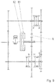
- FIG. 2 schematically shows a second exemplary embodiment of a hybrid drive according to the invention, including a transmission according to the invention for a motor vehicle.
- the transmission includes two gear planes, namely a first gear plane RE 1 and a second gear plane RE 2 .
- the transmission includes four engagement devices, namely a first engagement device SE 1 , a second engagement device SE 2 , a third engagement device SE 3 , and a fourth engagement device SE 4 .
- a first input shaft is designed as a hollow shaft 20 and a second input shaft is designed as a solid shaft 21 , which are arranged coaxially to each other.
- the hollow shaft 20 and the solid shaft 21 are arranged in such a way that one part of the solid shaft 21 is enclosed by the hollow shaft 20 .
- the first shaft 3 includes two power transmission elements which are designed as idler gears.
- the first shaft 3 includes a first idler gear 9 and a second idler gear 10 as the power transmission elements.
- the second shaft 4 includes two other power transmission elements which are designed as idler gears.
- the second shaft 4 includes a first other idler gear 11 and a second other idler gear 12 as the power transmission elements.
- the hollow shaft 20 includes a first input shaft power transmission element and the solid shaft 21 includes a second input shaft power transmission element.
- the two input shaft power transmission elements are designed as fixed gears, wherein, in the following, the first input shaft power transmission element is referred to as the first fixed gear 13 and the second input shaft power transmission element is referred to as the second fixed gear 14 .
- the first fixed gear 13 is connected to the hollow shaft 20 in a rotationally fixed manner.
- the second fixed gear 14 is connected to the solid shaft 21 in a rotationally fixed manner.
- the first fixed gear 13 intermeshes with the first idler gear 9 and the first other idler gear 11 .
- the second fixed gear 14 intermeshes with the second idler gear 10 and the second other idler gear 12 .
- the first engagement device SE 1 is designed as a single shift element and includes a first shift element S 2 and a first engagement means SB 1 .
- the first engagement means SB 1 is axially movable along the second shaft 4 and can engage the first shift element S 2 .
- the first other idler gear 11 In the engaged condition of the first shift element S 2 , the first other idler gear 11 is connected to the second shaft 4 in a rotationally fixed manner.
- no torque is transmitted from the first other idler gear 11 to the second shaft 4 .
- the second engagement device SE 2 is designed as a double shift element and includes a second engagement means SB 2 , a second shift element S 3 , and a third shift element SK.
- the second engagement means SB 2 is axially movable along the second shaft 4 .
- the second shift element S 3 or the third shift element SK is engaged, depending on the direction of motion of the second engagement means SB 2 .
- the second other idler gear 12 is connected to the second shaft 4 in a rotationally fixed manner.
- the second other idler gear 12 is connected to the first other idler gear 11 in a rotationally fixed manner. This means, when a third shift element SK is engaged, there is no rotationally fixed connection of the first other idler gear 11 and the second other idler gear 12 to the second shaft 4 .
- the third engagement device SE 3 is designed as a double shift element, in particular as a dual clutch, and includes a fourth shift element K 1 and a fifth shift element K 2 .
- the hollow shaft 20 is connected to the internal combustion engine VM in a rotationally fixed manner.
- the solid shaft 21 is connected to the internal combustion engine VM in a rotationally fixed manner.
- the fourth engagement device SE 4 includes two single shift elements.
- the fourth engagement device SE 4 includes a sixth shift element S 4 and a seventh shift element S 5 .
- the fourth engagement device SE 4 includes a third engagement means SB 3 , which is associated with the sixth shift element S 4 , and a fourth engagement means SB 4 which is associated with the seventh shift element S 5 .
- the first idler gear 9 is connected to the first shaft 3 in a rotationally fixed manner.
- the second idler gear 10 is connected to the first shaft 3 in a rotationally fixed manner.
- the transmission includes a connecting means, which is not represented in FIG. 2 and via which the electric machine EM, preferably an electric motor, is coupled to the transmission in a rotationally fixed manner.
- the electric machine EM is connected to the third engagement device SE 3 in a rotationally fixed manner via the connecting means.
- FIG. 3 schematically shows a third exemplary embodiment of a hybrid drive according to the invention, including a transmission according to the invention for a motor vehicle.
- the exemplary embodiment represented in FIG. 3 differs from the second exemplary embodiment represented in FIG. 2 with respect to the arrangement and coupling of the electric machine EM.
- the electric machine EM is connected to the hollow shaft 20 in a rotationally fixed manner by the connecting means 16 .
- FIG. 4 schematically shows a fourth exemplary embodiment of a hybrid drive according to the invention, including a transmission according to the invention for a motor vehicle.
- the fourth exemplary embodiment differs from the third exemplary embodiment represented in FIG. 3 in that a separating clutch K 0 is present, which is drivingly connected upstream from the third engagement device SE 3 in traction operation.
- the separating clutch K 0 is arranged between the internal combustion engine VM and the transmission and is connected to the internal combustion engine VM in a rotationally fixed manner.
- the separating clutch K 0 is connected to the third engagement device SE 3 in a rotationally fixed manner by an input shaft 15 of the transmission.
- the electric machine EM is connected to the input shaft 15 in a rotationally fixed manner via the connecting means 16 .
- the shift matrix for the transmission shown in FIGS. 2 to 4 is represented in FIG. 5 .
- All three transmissions have one reverse gear for a purely electric reverse operation.
- all three transmissions have one forward gear for a purely electric forward operation.
- the first forward gear is implemented for the purely electric forward operation and the reverse gear is implemented for the purely electric reverse operation by engaging the first shift element S 2 .
- the fourth and/or the fifth shift element K 1 , K 2 in order to select the reverse gear, must be engaged in addition to the first shift element S 2 , wherein the remaining shift elements are disengaged.
- the purely electric forward gear in the third exemplary embodiment shown in FIG. 3 can be implemented exclusively by the engaged first shift element S 2 , however, without the need to engage further shift elements.
- An internal combustion engine-assisted start takes place in a second forward gear.
- the first shift element S 2 and the fourth shift element K 1 are engaged, wherein the remaining shift elements are disengaged.
- a change-over from the second forward gear into a third forward gear can be implemented by disengaging the first and the fourth shift elements S 2 , K 1 and by engaging the fifth and the second shift elements K 2 , S 3 , wherein the remaining shift elements are disengaged.
- a change-over from the third forward gear into a fourth forward gear can be implemented by disengaging the second and the fifth shift elements S 3 , K 2 and by engaging the fourth and the sixth shift elements K 1 , S 4 , wherein the remaining shift elements are disengaged.
- a change-over from the fourth forward gear into a fifth forward gear can be implemented by disengaging the fourth and the sixth shift elements K 1 , S 4 and by engaging the fifth and the seventh shift elements K 2 , S 5 , wherein the remaining shift elements are disengaged.
- a change-over from the fifth forward gear into a sixth forward gear can be implemented by disengaging the seventh shift element S 5 and engaging the third and the sixth shift elements SK, S 4 , wherein the fifth shift element K 2 is engaged and the remaining shift elements are disengaged.
- the second other idler gear 12 is connected to the first other idler gear 11 in a rotationally fixed manner without there being a rotationally fixed connection to the second shaft 4 .
- FIG. 6 schematically shows a fifth exemplary embodiment of a hybrid drive according to the invention, including a transmission according to the invention for a motor vehicle.
- the transmission differs from the second exemplary embodiment represented in FIG. 2 in that yet another power transmission element R is provided.
- the provision of yet another power transmission element R offers the advantage that the reverse operation must no longer take place purely electrically.
- the reverse operation can be implemented purely electrically by utilizing the internal combustion engine.
- the further power transmission element is designed as a gearwheel and is arranged between the first fixed gear 13 and the first idler gear 9 in such a way that it is engaged with the first fixed gear 13 and the first idler gear 9 .
- the fourth engagement device SB 4 is designed as a double shift element.
- the fourth engagement device SB 4 includes a single engagement means, namely a single fifth engagement means SB 5 , wherein the sixth shift element S 4 or the seventh shift element S 5 is engaged depending on the direction of motion of the fifth engagement means SB 5 .
- FIG. 7 schematically shows a sixth exemplary embodiment of a hybrid drive according to the invention, including a transmission according to the invention for a motor vehicle. This differs from the fifth exemplary embodiment represented in FIG. 6 by the arrangement and the coupling of the electric machine EM.
- the electric machine EM is no longer connected to the third engagement device SE 3 in a rotationally fixed manner. Instead, the electric machine EM is connected to the hollow shaft 10 in a rotationally fixed manner via the connecting means 16 .
- FIG. 8 schematically shows a seventh exemplary embodiment of a hybrid drive according to the invention, including a transmission according to the invention for a motor vehicle.
- the exemplary embodiment represented in FIG. 8 differs from the fourth exemplary embodiment represented in FIG. 4 in that yet another power transmission element R in the form of a gearwheel is provided, which is arranged between the first fixed gear 13 and the first idler gear 9 .
- a reverse operation can be implemented purely by utilizing the internal combustion engine.
- the fourth engagement device SB 4 is designed as a double shift element.
- the fourth engagement device SB 4 includes a single engagement means, namely a single fifth engagement means SB 5 , wherein the sixth shift element S 4 or the seventh shift element S 5 is engaged depending on the direction of motion of the fifth engagement means SB 5 .
- FIG. 9 shows an eighth exemplary embodiment of a transmission according to the invention. This differs from the fifth exemplary embodiment shown in FIG. 6 in that no electric machine is provided. This means, in the case of the transmission represented in FIG. 9 , a forward operation and a reverse operation are implemented purely by utilizing the internal combustion engine.
- FIG. 10 shows a ninth exemplary embodiment of a transmission according to the invention. This differs from the eighth exemplary embodiment represented in FIG. 9 with respect to the design of the fourth engagement device SE 4 .
- the fourth engagement device SE 4 is not designed as a double shift element. Instead, the fourth engagement device includes two single shift elements, namely the sixth shift element S 4 and the seventh shift element S 5 , each of which can be actuated via a separate engagement means.
- the first idler gear 9 is connected to the first shaft 3 in a rotationally fixed manner.
- the second idler gear 10 is connected to the first shaft 3 in a rotationally fixed manner.
- FIG. 11 shows a shift matrix for the exemplary embodiments shown in FIGS. 6 to 10 .
- a reverse gear can be implemented by engaging the fourth shift element K 1 and the sixth shift element S 4 , wherein the remaining shift elements are disengaged.
- a change-over from the reverse gear into the first forward gear can be implemented by disengaging the sixth shift element S 4 and engaging the third and the seventh shift elements SK, S 5 , wherein the fourth shift element K 1 is engaged and the remaining shift elements are disengaged.
- a change-over from the first forward gear into the second forward gear can be implemented by disengaging the fourth and the third shift elements K 1 , SK and by engaging the fifth shift element K 2 , wherein the seventh shift element S 5 is engaged and the remaining shift elements are disengaged.
- a change-over from the second forward gear into the third forward gear can be implemented by disengaging the fifth and the seventh shift elements K 2 , S 5 and by engaging the fourth and the first elements K 1 , S 2 , wherein the remaining shift elements are disengaged.
- a change-over from the third forward gear into the fourth forward gear can be implemented by disengaging the fourth and the first shift elements K 1 , S 2 and by engaging the fifth and the second shift elements K 2 , S 3 , wherein the remaining shift elements are disengaged.
Landscapes
- Engineering & Computer Science (AREA)
- Mechanical Engineering (AREA)
- General Engineering & Computer Science (AREA)
- Chemical & Material Sciences (AREA)
- Combustion & Propulsion (AREA)
- Transportation (AREA)
- Structure Of Transmissions (AREA)
Applications Claiming Priority (3)
| Application Number | Priority Date | Filing Date | Title |
|---|---|---|---|
| DE102015224647.7A DE102015224647A1 (de) | 2015-12-09 | 2015-12-09 | Getriebe für ein Kraftfahrzeug |
| DE102015224647.7 | 2015-12-09 | ||
| PCT/EP2016/077431 WO2017097534A1 (de) | 2015-12-09 | 2016-11-11 | Getriebe für ein kraftfahrzeug |
Publications (2)
| Publication Number | Publication Date |
|---|---|
| US20180363730A1 US20180363730A1 (en) | 2018-12-20 |
| US11221060B2 true US11221060B2 (en) | 2022-01-11 |
Family
ID=57286507
Family Applications (1)
| Application Number | Title | Priority Date | Filing Date |
|---|---|---|---|
| US16/060,479 Active 2038-12-21 US11221060B2 (en) | 2015-12-09 | 2016-11-11 | Transmission for a motor vehicle |
Country Status (4)
| Country | Link |
|---|---|
| US (1) | US11221060B2 (zh) |
| CN (1) | CN108474455B (zh) |
| DE (1) | DE102015224647A1 (zh) |
| WO (1) | WO2017097534A1 (zh) |
Cited By (1)
| Publication number | Priority date | Publication date | Assignee | Title |
|---|---|---|---|---|
| US20230106079A1 (en) * | 2021-10-04 | 2023-04-06 | Dana Graziano S.R.L. | Hybrid vehicle transmission with a mechanical reverse system |
Families Citing this family (10)
| Publication number | Priority date | Publication date | Assignee | Title |
|---|---|---|---|---|
| JP6415493B2 (ja) * | 2016-08-09 | 2018-10-31 | 株式会社ミスミ | 設計支援方法、サーバ及び設計支援システム |
| DE102018220721B4 (de) | 2018-01-31 | 2023-10-12 | Ford Global Technologies, Llc | Doppelkupplungsgetriebe für Kraftfahrzeuge mit Hybridantrieb |
| KR102529917B1 (ko) * | 2018-10-11 | 2023-05-08 | 현대자동차주식회사 | 차량의 주행 제어 장치 및 방법, 그리고 차량 시스템 |
| DE102019003780B3 (de) * | 2019-05-29 | 2020-07-02 | Daimler Ag | Hybridantriebsystem |
| DE102019210833A1 (de) * | 2019-07-22 | 2021-01-28 | Zf Friedrichshafen Ag | Getriebeanordnung, Hybrid-Getriebeanordnung, Hybrid-Antriebsstrang sowie Kraftfahrzeug |
| DE102019007299A1 (de) * | 2019-10-21 | 2021-04-22 | Daimler Ag | Hybrid-Doppelkupplungsgetriebe |
| CN115003931A (zh) * | 2019-11-05 | 2022-09-02 | 沃尔沃卡车集团 | 用于车辆的变速器组件 |
| EP4055302B1 (en) * | 2019-11-05 | 2023-08-16 | Volvo Truck Corporation | Transmission assembly for a vehicle |
| EP4208655A1 (de) * | 2020-09-01 | 2023-07-12 | Deere & Company | Getriebeeinheit, getriebeanordnung und landwirtschaftliches zugfahrzeug |
| DE102021200142A1 (de) | 2021-01-11 | 2022-07-14 | Zf Friedrichshafen Ag | Getriebeanordnung, Hybrid-Getriebeanordnung, Hybrid-Antriebsstrang sowie Kraftfahrzeug |
Citations (9)
| Publication number | Priority date | Publication date | Assignee | Title |
|---|---|---|---|---|
| DE102008000647A1 (de) | 2008-03-13 | 2009-09-17 | Zf Friedrichshafen Ag | Anordnung zum Schalten von zumindest einem Losrad |
| US20100311540A1 (en) * | 2007-05-14 | 2010-12-09 | Gereon Hellenbroich | Method for the operation of a hybrid drive system and hybrid drive system comprising two sub-transmissions |
| CN201849308U (zh) | 2010-09-30 | 2011-06-01 | 长城汽车股份有限公司 | 汽车混合动力系统 |
| DE102011005532A1 (de) | 2011-03-15 | 2012-09-20 | Zf Friedrichshafen Ag | Hybridantrieb eines Kraftfahrzeugs |
| US8955411B2 (en) * | 2011-06-22 | 2015-02-17 | GETRAG Getriebe—und Zahnradfabrik Hermann Hagenmeyer GmbH & Cie KG | Hybrid drive train and gear-changing method |
| US9789754B2 (en) * | 2014-11-14 | 2017-10-17 | Saic Motor Corporation Limited | Dual-motor power system and dual-motor hybrid power system for vehicle |
| US9834083B2 (en) * | 2013-03-21 | 2017-12-05 | GETRAG Getriebe—und Zahnradfabrik Hermann Hagen | Drive train for a motor vehicle |
| US10144309B2 (en) * | 2015-05-29 | 2018-12-04 | Saic Motor Corporation Limited | Dual motor power system and control method for pure electric vehicle |
| US10781914B2 (en) * | 2015-08-31 | 2020-09-22 | Borgwarner Torqtransfer Systems Ab | Method of controlling a drive train |
Family Cites Families (3)
| Publication number | Priority date | Publication date | Assignee | Title |
|---|---|---|---|---|
| DE102010030569A1 (de) * | 2010-06-28 | 2011-12-29 | Zf Friedrichshafen Ag | Hybridantrieb eines Kraftfahrzeugs und Verfahren zu dessen Steuerung |
| DE102013211591B4 (de) * | 2013-06-20 | 2024-03-28 | Zf Friedrichshafen Ag | Anordnung aus einem Getriebe und einer elektrischen Maschine für einen Hybridantrieb und Hybridantrieb |
| KR101588775B1 (ko) * | 2013-12-31 | 2016-01-26 | 현대자동차 주식회사 | 차량용 변속장치 |
-
2015
- 2015-12-09 DE DE102015224647.7A patent/DE102015224647A1/de active Pending
-
2016
- 2016-11-11 CN CN201680071670.XA patent/CN108474455B/zh active Active
- 2016-11-11 WO PCT/EP2016/077431 patent/WO2017097534A1/de active Application Filing
- 2016-11-11 US US16/060,479 patent/US11221060B2/en active Active
Patent Citations (10)
| Publication number | Priority date | Publication date | Assignee | Title |
|---|---|---|---|---|
| US20100311540A1 (en) * | 2007-05-14 | 2010-12-09 | Gereon Hellenbroich | Method for the operation of a hybrid drive system and hybrid drive system comprising two sub-transmissions |
| DE102008000647A1 (de) | 2008-03-13 | 2009-09-17 | Zf Friedrichshafen Ag | Anordnung zum Schalten von zumindest einem Losrad |
| CN201849308U (zh) | 2010-09-30 | 2011-06-01 | 长城汽车股份有限公司 | 汽车混合动力系统 |
| DE102011005532A1 (de) | 2011-03-15 | 2012-09-20 | Zf Friedrichshafen Ag | Hybridantrieb eines Kraftfahrzeugs |
| US8960033B2 (en) | 2011-03-15 | 2015-02-24 | Zf Friedrichshafen Ag | Hybrid drive of a motor vehicle |
| US8955411B2 (en) * | 2011-06-22 | 2015-02-17 | GETRAG Getriebe—und Zahnradfabrik Hermann Hagenmeyer GmbH & Cie KG | Hybrid drive train and gear-changing method |
| US9834083B2 (en) * | 2013-03-21 | 2017-12-05 | GETRAG Getriebe—und Zahnradfabrik Hermann Hagen | Drive train for a motor vehicle |
| US9789754B2 (en) * | 2014-11-14 | 2017-10-17 | Saic Motor Corporation Limited | Dual-motor power system and dual-motor hybrid power system for vehicle |
| US10144309B2 (en) * | 2015-05-29 | 2018-12-04 | Saic Motor Corporation Limited | Dual motor power system and control method for pure electric vehicle |
| US10781914B2 (en) * | 2015-08-31 | 2020-09-22 | Borgwarner Torqtransfer Systems Ab | Method of controlling a drive train |
Non-Patent Citations (2)
| Title |
|---|
| German Search Report DE102015224647.7 dated Dec. 16, 2016. (8 pages). |
| International Search Report (English Translation) PCT/EP2016/077431, dated Jan. 10, 2017. (2 pages). |
Cited By (1)
| Publication number | Priority date | Publication date | Assignee | Title |
|---|---|---|---|---|
| US20230106079A1 (en) * | 2021-10-04 | 2023-04-06 | Dana Graziano S.R.L. | Hybrid vehicle transmission with a mechanical reverse system |
Also Published As
| Publication number | Publication date |
|---|---|
| CN108474455A (zh) | 2018-08-31 |
| US20180363730A1 (en) | 2018-12-20 |
| CN108474455B (zh) | 2021-02-02 |
| DE102015224647A1 (de) | 2017-06-14 |
| WO2017097534A1 (de) | 2017-06-15 |
Similar Documents
| Publication | Publication Date | Title |
|---|---|---|
| US11221060B2 (en) | Transmission for a motor vehicle | |
| JP6951367B2 (ja) | 自動車用の変速機 | |
| CN110366501B (zh) | 动力传递装置 | |
| CN105102858B (zh) | 变速器以及用于运行变速器的方法 | |
| EP2529967B1 (en) | Electric propulsion system for vehicles | |
| KR20190057981A (ko) | 전기차량용 변속기 | |
| JP6656369B2 (ja) | 車両のパワートレイン | |
| CN105142950A (zh) | 马达变速器单元以及具有这种马达变速器单元的轮毂驱动装置 | |
| US7610826B2 (en) | Parallel axes type transmission having a plurality of idle drive routes | |
| US20110251011A1 (en) | Hybrid powertrain and dual clutch transmission | |
| KR101360435B1 (ko) | 전기차량용 변속기 | |
| US11821499B2 (en) | Power transmission device | |
| US9752654B2 (en) | Dual-clutch transmission | |
| JP2013063756A (ja) | 車両のハイブリッドパワートレーン | |
| EP2730808B1 (en) | Transmission | |
| KR20130104386A (ko) | 하이브리드 파워트레인 | |
| KR101181746B1 (ko) | 더블 클러치 변속기 | |
| US20100018336A1 (en) | Transmission for industrial vehicle | |
| CN113348101A (zh) | 混合动力系统 | |
| CN114025979A (zh) | 车辆的驱动装置 | |
| EP2730446B1 (en) | Multiple speed power take off | |
| JP2013160282A (ja) | ツインクラッチ式変速機 | |
| CN108454381B (zh) | 用于机动车的变速器 | |
| CN107747613B (zh) | 双离合自动变速器及具有该双离合自动变速器的车辆 | |
| CN218177898U (zh) | 一种具有挡位切换装置的通用发动机 |
Legal Events
| Date | Code | Title | Description |
|---|---|---|---|
| AS | Assignment |
Owner name: ZF FRIEDRICHSHAFEN AG, GERMANY Free format text: ASSIGNMENT OF ASSIGNORS INTEREST;ASSIGNORS:WAFZIG, JURGEN;WECHS, MICHAEL;WEHLEN, TIMO;AND OTHERS;REEL/FRAME:046024/0626 Effective date: 20180424 |
|
| FEPP | Fee payment procedure |
Free format text: ENTITY STATUS SET TO UNDISCOUNTED (ORIGINAL EVENT CODE: BIG.); ENTITY STATUS OF PATENT OWNER: LARGE ENTITY |
|
| STPP | Information on status: patent application and granting procedure in general |
Free format text: APPLICATION DISPATCHED FROM PREEXAM, NOT YET DOCKETED |
|
| STPP | Information on status: patent application and granting procedure in general |
Free format text: DOCKETED NEW CASE - READY FOR EXAMINATION |
|
| STPP | Information on status: patent application and granting procedure in general |
Free format text: NON FINAL ACTION MAILED |
|
| STPP | Information on status: patent application and granting procedure in general |
Free format text: RESPONSE TO NON-FINAL OFFICE ACTION ENTERED AND FORWARDED TO EXAMINER |
|
| STPP | Information on status: patent application and granting procedure in general |
Free format text: NOTICE OF ALLOWANCE MAILED -- APPLICATION RECEIVED IN OFFICE OF PUBLICATIONS |
|
| STPP | Information on status: patent application and granting procedure in general |
Free format text: PUBLICATIONS -- ISSUE FEE PAYMENT VERIFIED |
|
| STCF | Information on status: patent grant |
Free format text: PATENTED CASE |