US11214440B2 - Receiving bin for a sorting machine - Google Patents
Receiving bin for a sorting machine Download PDFInfo
- Publication number
- US11214440B2 US11214440B2 US17/155,489 US202117155489A US11214440B2 US 11214440 B2 US11214440 B2 US 11214440B2 US 202117155489 A US202117155489 A US 202117155489A US 11214440 B2 US11214440 B2 US 11214440B2
- Authority
- US
- United States
- Prior art keywords
- guiding member
- receiving bin
- chute
- guided
- inlet chute
- Prior art date
- Legal status (The legal status is an assumption and is not a legal conclusion. Google has not performed a legal analysis and makes no representation as to the accuracy of the status listed.)
- Active
Links
Images


Classifications
-
- B—PERFORMING OPERATIONS; TRANSPORTING
- B65—CONVEYING; PACKING; STORING; HANDLING THIN OR FILAMENTARY MATERIAL
- B65G—TRANSPORT OR STORAGE DEVICES, e.g. CONVEYORS FOR LOADING OR TIPPING, SHOP CONVEYOR SYSTEMS OR PNEUMATIC TUBE CONVEYORS
- B65G11/00—Chutes
- B65G11/20—Auxiliary devices, e.g. for deflecting, controlling speed of, or agitating articles or solids
-
- B—PERFORMING OPERATIONS; TRANSPORTING
- B07—SEPARATING SOLIDS FROM SOLIDS; SORTING
- B07C—POSTAL SORTING; SORTING INDIVIDUAL ARTICLES, OR BULK MATERIAL FIT TO BE SORTED PIECE-MEAL, e.g. BY PICKING
- B07C3/00—Sorting according to destination
- B07C3/008—Means for collecting objects, e.g. containers for sorted mail items
-
- B—PERFORMING OPERATIONS; TRANSPORTING
- B07—SEPARATING SOLIDS FROM SOLIDS; SORTING
- B07C—POSTAL SORTING; SORTING INDIVIDUAL ARTICLES, OR BULK MATERIAL FIT TO BE SORTED PIECE-MEAL, e.g. BY PICKING
- B07C5/00—Sorting according to a characteristic or feature of the articles or material being sorted, e.g. by control effected by devices which detect or measure such characteristic or feature; Sorting by manually actuated devices, e.g. switches
- B07C5/36—Sorting apparatus characterised by the means used for distribution
- B07C5/38—Collecting or arranging articles in groups
-
- B—PERFORMING OPERATIONS; TRANSPORTING
- B07—SEPARATING SOLIDS FROM SOLIDS; SORTING
- B07C—POSTAL SORTING; SORTING INDIVIDUAL ARTICLES, OR BULK MATERIAL FIT TO BE SORTED PIECE-MEAL, e.g. BY PICKING
- B07C5/00—Sorting according to a characteristic or feature of the articles or material being sorted, e.g. by control effected by devices which detect or measure such characteristic or feature; Sorting by manually actuated devices, e.g. switches
- B07C5/36—Sorting apparatus characterised by the means used for distribution
-
- B—PERFORMING OPERATIONS; TRANSPORTING
- B65—CONVEYING; PACKING; STORING; HANDLING THIN OR FILAMENTARY MATERIAL
- B65G—TRANSPORT OR STORAGE DEVICES, e.g. CONVEYORS FOR LOADING OR TIPPING, SHOP CONVEYOR SYSTEMS OR PNEUMATIC TUBE CONVEYORS
- B65G65/00—Loading or unloading
- B65G65/30—Methods or devices for filling or emptying bunkers, hoppers, tanks, or like containers, of interest apart from their use in particular chemical or physical processes or their application in particular machines, e.g. not covered by a single other subclass
- B65G65/32—Filling devices
-
- B—PERFORMING OPERATIONS; TRANSPORTING
- B65—CONVEYING; PACKING; STORING; HANDLING THIN OR FILAMENTARY MATERIAL
- B65G—TRANSPORT OR STORAGE DEVICES, e.g. CONVEYORS FOR LOADING OR TIPPING, SHOP CONVEYOR SYSTEMS OR PNEUMATIC TUBE CONVEYORS
- B65G69/00—Auxiliary measures taken, or devices used, in connection with loading or unloading
-
- B—PERFORMING OPERATIONS; TRANSPORTING
- B65—CONVEYING; PACKING; STORING; HANDLING THIN OR FILAMENTARY MATERIAL
- B65G—TRANSPORT OR STORAGE DEVICES, e.g. CONVEYORS FOR LOADING OR TIPPING, SHOP CONVEYOR SYSTEMS OR PNEUMATIC TUBE CONVEYORS
- B65G2201/00—Indexing codes relating to handling devices, e.g. conveyors, characterised by the type of product or load being conveyed or handled
- B65G2201/02—Articles
- B65G2201/0202—Agricultural and processed food products
-
- B—PERFORMING OPERATIONS; TRANSPORTING
- B65—CONVEYING; PACKING; STORING; HANDLING THIN OR FILAMENTARY MATERIAL
- B65G—TRANSPORT OR STORAGE DEVICES, e.g. CONVEYORS FOR LOADING OR TIPPING, SHOP CONVEYOR SYSTEMS OR PNEUMATIC TUBE CONVEYORS
- B65G2207/00—Indexing codes relating to constructional details, configuration and additional features of a handling device, e.g. Conveyors
- B65G2207/26—Hygienic features, e.g. easy to sanitize
Definitions
- the invention concerns a sorting machine and more particularly a receiving bin for a sorting machine used for receiving non-conforming products from a batch of conveyed products.
- the receiving bin of the present invention is movable between an operative configuration and an inoperative configuration.
- a sorting machine of the type known in the art automatically inspects a plurality of products for conformity and separates defective ones that do not conform with a predetermined set of specifications or standards.
- Sorting machines are employed in a variety of environments to carry out sorting operations. Typically, a sorting operation is an integral part of the food processing industry. Sorting is carried out for meat and fish products, dairy products such as cheese, agricultural products such as nuts etc.
- the sensitive nature of the products that the machines handle requires frequent cleaning of the components such as conveyor belts, ejection containers, receiving bins, etc., that could come in contact with the product that is processed. Cross contact with allergens could increase the risk of contamination many folds, thereby posing severe health risks to end consumers of the product.
- the main problem associated with cleaning the sorting machines is the difficulty in gaining optimum access to conveyor belts, ejection containers, and receiving bins. This problem severely undermines the cleaning efforts of operators, giving rise to ever increasing infestation.
- the receiving bin is arranged in close proximity to the outfeed conveyor belt to ensure successfully transfer of rejected product from the outfeed conveyor belt directly into the receiving bin.
- the conveyor belt is loosened up before it is tilted upwards from the frame of the sorting machine.
- the receiving bin should be moved out of the path of the outfeed conveyor belt because in its working position the receiving bin directly interferes with the outfeed conveyor belt.
- the receiving bin is arranged to swivel about a vertical axis thereby moving the receiving bin out of the way of the conveyor belts.
- An object of the present invention is to provide a receiving bin for a sorting machine, particularly, a receiving bin that is movable to alternate between an operative configuration in which the receiving bin is configurable for receiving a rejected product from the sorting machine, and an inoperative configuration in which the receiving bin is configurable for servicing and maintenance.
- the receiving bin comprises an inlet chute and a transfer chute.
- the receiving bin for the sorting machine according to the invention, further comprises a configuration altering mechanism connecting said inlet chute, and said transfer chute.
- the configuration altering mechanism comprises at least one first guiding member having a receiving position and a separating position; at least one first guided member receivable within the first guiding member; at least one second guiding member having a front end position and a rear end position located opposing the front end position, and at least one second guided member receivable within the second guiding member and configured to be continuously movable between the front end position and the rear end position.
- the receiving bin is in operative configuration when the first guided member is located in the receiving position of the first guiding member and the second guided member is located in the front end position of the second guiding member.
- the receiving bin is in inoperative configuration when the second guided member is located in the rear end position of the second guiding member and the first guided member is located outside of the first guiding member.
- the inventive arrangement offers several advantages and most notable among them is the easy access to conveyor belts for cleaning when the receiving bin is moved into an inoperative configuration. Besides, it is not necessary to separate the receiving bin from the frame of the sorting machine for the purpose of servicing and maintenance.
- the inlet chute and the transfer chute are sufficiently exposed to waterjet during a cleaning event, which is essential to maintain aseptic conditions and hygienic environment, especially when the sorting machine is commissioned in a production plant where food items such as meat, fish, cheese, or nuts are processed and packaged.
- the configuration altering mechanism is located on the left hand side and right hand side of the receiving bin, when the receiving bin is disposed in an operative configuration.
- the terms left hand side and right hand side within the present context relate to the display of the sorting machine as it presents itself to an operator of the sorting machine when the sorting machine is in a working condition.
- the spatial directions and dimensions are accordingly defined as width, height and depth as seen by a person standing in front of such a display.
- the configuration altering mechanism enables the operator to move the receiving bin between an operative configuration and an inoperative configuration.
- the load acting on the receiving bin, and particularly the inlet chute during the operation of the sorting machine is evenly distributed thereby lowering the incidence of failure.
- the movement of the receiving bin between an operative configuration and an inoperative configuration is smoothened when the configuration altering mechanism supports the inlet chute from two opposing sides.
- the configuration altering mechanism further comprises at least a third guiding member having a common position with the at least one second guiding member.
- the common position provides entrance to the second guided member such that the inlet chute is separated from the transfer chute when the second guided member is passed through the third guiding member and fully moved outside the third guiding member.
- the receiving bin consists of a reinforcing member provided in a region surrounding the second guiding member and the third guiding member.
- the reinforcing member advantageously, adds strength to the overall structure of the receiving bin and minimizes the incidence of structural failure.
- the first guiding member, the second guiding member, and the third guiding member are formed as slots on the receiving bin by way of removing the material. Adding a reinforcing member to the receiving bin compensates for the material removed and hence contributes to the structural integrity and durability of the receiving bin.
- the first guiding member consists of a separating position and a receiving position such that the receiving bin is in the operative configuration when the first guided member is located in the receiving position of the first guiding member.
- the receiving position is arcuate in configuration and is shaped to match the surface profile of the first guided member.
- the separating position is configured as an open end through which the first guided member exits the first guiding member. The exit of guided member through the separating position initiates the transition of receiving bin from an operative configuration to an inoperative configuration.
- the third guiding member is transversely connected to the second guiding member such that the second guided member is movable from the second guiding member into the third guiding member and then further along the third guiding member to the outside so as to separate the inlet chute from the transfer chute.
- the third guiding member comprises an inner end position and an outer end position such that the third guiding member is connected to the second guiding member at the inner end position.
- This arrangement of connecting the third guiding member to the second guiding member facilitates the movement of second guided member from the second guiding member into the third guiding member.
- the inlet chute is separated from the transfer chute when the second guided member reaches the outer end position.
- the inlet chute further comprises a first handle for applying force in a direction away from the receiving bin so as to move the first guided member outside of the first guiding member.
- the inlet chute further comprises a second handle for applying force to the inlet chute to move the second guided member along and to the rear end position of the second guiding member and subsequently rotate the inlet chute about an axis formed by the second guided member so as to alternate the receiving bin into an inoperative configuration.
- the inlet chute and the transfer chute are connected together by the second guided member.
- the second guided member is continuously moveable within the second guiding member.
- the second guided member is movable between the front end position and the rear end position of the second guiding member.
- the inlet chute and the transfer chute remain connected to each other as long as the second guided member continues to remain positioned within the second guiding member.
- the first guided member and the second guided member are located on the inlet chute.
- the first guiding member, second guiding member, and the third guiding member are located on the transfer chute.
- the first guided member and the second guided member are located on the transfer chute and the first guiding member, second guiding member, and the third guiding member are located on the inlet chute.
- the first guided member and the first guiding member complement each other.
- the second guided member and the second guiding member complement each other.
- the reinforcing member is located on the transfer chute or inlet chute in the region surrounding the second guiding member and the third guiding member.
- first guiding member, the second guiding member, and the third guiding member are configured as slots.
- first guided member and the second guided member are configured as pins.
- a sorting machine is provided with a receiving bin containing the aforementioned features, functions, and advantages.
- a method for altering the configuration of a receiving bin is disclosed.
- the configuration of the receiving bin is altered from an operative configuration in which the receiving bin is configured for receiving a rejected product from a sorting machine into an inoperative configuration in which the receiving bin is configured for servicing and maintenance.
- the method involves the step of moving the inlet chute in the direction away from the transfer chute so as to move the first guided member outside of the first guiding member. Then moving the inlet chute further in the direction away from the transfer chute so as to move the second guided member within the second guiding member until the second guided member reaches the rear end position of the second guiding member. Finally, rotating the inlet chute about an axis formed by the second guided member so as to finally move the receiving bin into the inoperative configuration.
- the method further contains steps through which the configuration of the receiving bin is altered from an operative configuration to a dismounted configuration.
- the receiving bin In an operative configuration, the receiving bin is configured for receiving a rejected product from a sorting machine.
- the inlet chute of the receiving bin is dismounted from the transfer chute for servicing, maintenance, and replacement.
- the method involves the steps of moving the inlet chute in the direction away from the transfer chute so as to move the first guided member outside the first guiding member. Subsequently, the inlet chute is separated from the transfer chute by passing the second guided member through the third guiding member and moving the second guided member fully outside the third guiding member.
- the method involves a step in which the inlet chute is moved in the direction away from the sorting machine by applying force on the first handle for pulling the inlet chute.
- the method further contains a step in which the inlet chute is rotated about the axis formed by the second guided member by applying force on the second handle for rotating the inlet chute.
- FIG. 1 shows a sorting machine with a receiving bin for receiving products rejected by the sorting machine
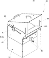
- FIG. 2 is a perspective view of the receiving bin, arranged in an operative configuration
- FIG. 3A is an exploded side view of an inlet chute of the receiving bin
- FIG. 3B is an exploded side view of a transfer chute of the receiving bin
- FIG. 4A is a side view of the receiving bin, arranged in an operative configuration
- FIG. 4B is a side view of the receiving bin, arranged in an inoperative configuration
- FIG. 1 illustrates a sorting machine 10 according to the invention in perspective.
- the high level components of the sorting machine 10 are infeed conveyor 12 , weighing conveyor 14 , outfeed conveyor 16 , detector 17 , display 18 , frame 19 , and receiving bin 20 .
- the infeed conveyor 12 , the weighing conveyor 14 , and the outfeed conveyor 16 are supported on the frame 19 and extend in the length wise direction of the frame 19 .
- the infeed conveyor 12 , the weighing conveyor 14 , and the outfeed conveyor 16 are arranged in-line so as to seamlessly move a product from an infeed end on the left hand side (LHS) to an outfeed end of the sorting machine 10 on the right hand side (RHS).
- LHS left hand side
- RHS right hand side
- the detector 17 is a metal detector capable of detecting any contaminants in the product, particularly contaminants such as very small metallic pieces.
- the detector 17 may in turn be a scanner which is equipped with state of the art optical systems such as cameras with which every product that is launched at the infeed end is inspected for quality and consistency.
- the detector 17 is arranged above the infeed conveyor 12 and surrounding it so as to let the infeed conveyor 12 pass through it.
- the weighing conveyor 14 positioned in line with the infeed conveyor 12 is mechanically connected to the weighing system ( 15 ) arranged beneath the weighing conveyor 14 .
- the weighing system ( 15 ) acting in combination with the weighing conveyor 14 determines the weight of the product and the resulting information is processed and analyzed instantaneously before the product is moved on to the outfeed conveyor 16 .
- the analyzed data is presented to the operator using the display 18 .
- the products that conform to the predetermined standards (weight, for instance) continue their passage along the outfeed conveyor 16 and are finally delivered for packaging or containerization.
- the products that fail to conform to the predetermined standards are removed or diverted from the outfeed conveyor 16 and moved into the receiving bin 20 to be collected later on by the operator for re-examination or quality control.
- FIG. 2 shows a receiving bin 20 by itself in its operative configuration, in which an inlet chute 30 , a transfer chute 40 , and a holding bin 50 are connected together.
- Mounting members 71 provided on the transfer chute 40 aid in attaching the receiving bin 20 to the frame 19 .
- Slots 65 are provided on the inlet chute 30 to allow passage of pertinent optical signals, such as a light beam, laser beam or infrared radiation, for the purpose of sensing, counting, or detection.
- the receiving bin 20 further contains a configuration altering mechanism 60 that primarily connects the inlet chute 30 and the transfer chute 40 .
- a reinforcing member R is added to the transfer chute 40 , preferably in close proximity to the configuration altering mechanism 60 , for the purpose of strengthening the body of the transfer chute 40 .
- FIGS. 3A and 3B show the receiving bin 20 of FIG. 2 in its dismounted configuration with the inlet chute 30 in FIG. 3A separated from the transfer chute 40 in FIG. 3B .
- FIG. 3A and FIG. 3B further show details about the configuration altering mechanism 60 .
- the configuration altering mechanism 60 of the present embodiment comprises a first guided member 32 and a second guided member 35 arranged on the inlet chute 30 , a first guiding member 42 and a second guiding member 45 provided on the transfer chute 40 .
- the first guided member 32 and the second guided member 35 are envisaged as pins.
- the first guiding member 42 and the second guiding member 45 are envisaged as slots that cooperate respectively with the first guided member 32 and the second guided member 35 both of which are configured as pins.
- the first guiding member 42 and the second guiding member 45 are uniquely configured to make them expedient for the smooth operation of the configuration altering mechanism 60 .
- the first guiding member 42 comprises a receiving position 43 and a separating position 44 , which in a way represents the position that the first guided member 32 , in the form of a pin takes within the first guiding member 42 , configured as a slot.
- the receiving position 43 is the closed end and the separating position 44 is the open end respectively of the first guiding member 42 .
- the second guiding member 45 comprises a front end position 46 and a rear end position 47 located opposing the front end position 46 .
- the front end position 46 and the rear end position 47 represent two extreme ends of the second guiding member 45 between which the second guided member 35 moves.
- This drawing further illustrates a third guiding member 48 that is transversely connected to the second guiding member 45 .
- the third guiding member 48 is envisaged as a slot provided on the transfer chute 40 and comprising an inner end position P 1 and an outer end position P 2 .
- the third guiding member 48 is transversely connected to the second guiding member 45 at its inner end position P 1 .
- the outer end position P 2 is located opposing the inner end position P 1 .
- the third guiding member 48 connected transversely to the second guiding member 45 at its inner end position P 1 enables the second guided member 35 to be movable from the second guiding member 45 into the third guiding member 48 and then further along the third guiding member 48 towards its outer end position P 2 until the second guided member 35 exits the third guiding member 48 thus separating the inlet chute 30 from the transfer chute 40 thereby altering the receiving bin 20 from an operative configuration in to a dismounted configuration.
- the reinforcing member R is not shown in FIG. 3B for the purpose of brining more visibility to the third guiding member 48 and its relationship with the second guiding member 45 . As is evident from FIG.
- the reinforcing member R can remain located in its position on the transfer chute 40 while the second guided member 35 is routed through the third guiding member 48 .
- the inlet chute 30 is provided with a first handle 36 for pulling the inlet chute 30 and a second handle 37 for rotating the inlet chute 30 . These handles improve the ergonomics of moving the receiving bin 20 from an operative configuration to an inoperative configuration and vice versa.
- FIGS. 4A and 4B illustrate a method for altering the configuration of the receiving bin 20 , particularly, from an operative configuration to an inoperative configuration.
- the receiving bin 20 as indicated in FIG. 4A is set to successfully receive a rejected product from the sorting machine 10 (illustrated in FIG. 1 ).
- the receiving bin 20 as shown in FIG. 4B is set up for carrying out servicing and maintenance.
- the inlet chute 30 which is in an operative configuration as shown in FIG. 4A , is moved in the direction away from the transfer chute 40 , which in turn leads to the movement of the first guided member 32 outside the first guiding member 42 .
- the inlet chute 30 is moved further in the direction away from the transfer chute 40 , which leads to the movement of the second guided member 35 within the second guiding member 45 until the second guided member 35 reaches the rear end position 47 of the second guiding member 45 . Finally, the inlet chute 30 is rotated about an axis formed by the second guided member 35 . Upon rotating the inlet chute 30 completely about the available angular span, the receiving bin 20 is fully moved into an inoperative configuration as shown in FIG. 4B . Beyond the operative and inoperative configurations, it is also possible to alter the configuration of the receiving bin 20 from an operative configuration in to a dismounted configuration, as shown in FIG. 3A and FIG.
Landscapes
- Engineering & Computer Science (AREA)
- Mechanical Engineering (AREA)
- Sorting Of Articles (AREA)
- Chutes (AREA)
- Branching, Merging, And Special Transfer Between Conveyors (AREA)
Applications Claiming Priority (3)
| Application Number | Priority Date | Filing Date | Title |
|---|---|---|---|
| EP20153547.3A EP3854490B1 (de) | 2020-01-24 | 2020-01-24 | Aufnahmebehälter für eine sortiermaschine und verfahren zur änderung seiner konfiguration |
| EP20153547.3 | 2020-01-24 | ||
| EP20153547 | 2020-01-24 |
Publications (2)
| Publication Number | Publication Date |
|---|---|
| US20210229920A1 US20210229920A1 (en) | 2021-07-29 |
| US11214440B2 true US11214440B2 (en) | 2022-01-04 |
Family
ID=69191936
Family Applications (1)
| Application Number | Title | Priority Date | Filing Date |
|---|---|---|---|
| US17/155,489 Active US11214440B2 (en) | 2020-01-24 | 2021-01-22 | Receiving bin for a sorting machine |
Country Status (5)
| Country | Link |
|---|---|
| US (1) | US11214440B2 (de) |
| EP (1) | EP3854490B1 (de) |
| CN (1) | CN113172009B (de) |
| DK (1) | DK3854490T3 (de) |
| ES (1) | ES3050626T3 (de) |
Families Citing this family (1)
| Publication number | Priority date | Publication date | Assignee | Title |
|---|---|---|---|---|
| GB2611327B (en) * | 2021-09-30 | 2024-07-03 | Terex Gb Ltd | Blending chute for material processing apparatus |
Citations (11)
| Publication number | Priority date | Publication date | Assignee | Title |
|---|---|---|---|---|
| US5192121A (en) * | 1991-03-15 | 1993-03-09 | Mark Stutler | Trash organizer for recycling |
| US5881889A (en) * | 1994-10-20 | 1999-03-16 | Scanvaegt A/S | Sorter system of the grader type |
| FR2813027A1 (fr) | 2000-08-18 | 2002-02-22 | Ecoda | Dispositif de triage pour recipients de deux sortes de forme differente |
| US6799684B2 (en) * | 2002-10-15 | 2004-10-05 | Batching Systems, Inc. | Multi-head portioning system |
| US7600643B2 (en) | 2005-12-16 | 2009-10-13 | Mettler-Toledo Garvens Gmbh | Sorting method and apparatus |
| US8528721B2 (en) * | 2009-12-10 | 2013-09-10 | Mettler-Toledo Garvens Gmbh | Sorting apparatus |
| US9617063B2 (en) * | 2014-05-07 | 2017-04-11 | Mettler-Toledo Garvens Gmbh | Discharge device for a holding bin |
| US9962743B2 (en) * | 2016-01-12 | 2018-05-08 | United States Postal Service | Systems and methods for high throughput sorting |
| US10577194B2 (en) * | 2018-01-26 | 2020-03-03 | Optimus Sorter Holding B.V. | Sorting device with improved capacity |
| US10712000B2 (en) | 2015-12-07 | 2020-07-14 | Kawasaki Jukogyo Kabushiki Kaisha | Ash discharge system |
| US10814355B2 (en) * | 2018-02-01 | 2020-10-27 | Mettler-Toledo Safeline Ltd. | Collection bin for an in-line product inspection system, and in-line product inspection system |
Family Cites Families (3)
| Publication number | Priority date | Publication date | Assignee | Title |
|---|---|---|---|---|
| GB2354993B (en) * | 1998-04-30 | 2002-10-30 | Scanvaegt Int As | Method and system for portioning and orientating whole fish or other elongate non-symetrical articles |
| JP2001047943A (ja) * | 1999-08-03 | 2001-02-20 | Toyoda Spinning & Weaving Co Ltd | 車両用荷室構造 |
| CN108380523A (zh) * | 2018-02-26 | 2018-08-10 | 江南大学 | 一种可调节采集视角的苹果自动分级装置 |
-
2020
- 2020-01-24 EP EP20153547.3A patent/EP3854490B1/de active Active
- 2020-01-24 ES ES20153547T patent/ES3050626T3/es active Active
- 2020-01-24 DK DK20153547.3T patent/DK3854490T3/da active
-
2021
- 2021-01-22 US US17/155,489 patent/US11214440B2/en active Active
- 2021-01-22 CN CN202110085595.5A patent/CN113172009B/zh active Active
Patent Citations (11)
| Publication number | Priority date | Publication date | Assignee | Title |
|---|---|---|---|---|
| US5192121A (en) * | 1991-03-15 | 1993-03-09 | Mark Stutler | Trash organizer for recycling |
| US5881889A (en) * | 1994-10-20 | 1999-03-16 | Scanvaegt A/S | Sorter system of the grader type |
| FR2813027A1 (fr) | 2000-08-18 | 2002-02-22 | Ecoda | Dispositif de triage pour recipients de deux sortes de forme differente |
| US6799684B2 (en) * | 2002-10-15 | 2004-10-05 | Batching Systems, Inc. | Multi-head portioning system |
| US7600643B2 (en) | 2005-12-16 | 2009-10-13 | Mettler-Toledo Garvens Gmbh | Sorting method and apparatus |
| US8528721B2 (en) * | 2009-12-10 | 2013-09-10 | Mettler-Toledo Garvens Gmbh | Sorting apparatus |
| US9617063B2 (en) * | 2014-05-07 | 2017-04-11 | Mettler-Toledo Garvens Gmbh | Discharge device for a holding bin |
| US10712000B2 (en) | 2015-12-07 | 2020-07-14 | Kawasaki Jukogyo Kabushiki Kaisha | Ash discharge system |
| US9962743B2 (en) * | 2016-01-12 | 2018-05-08 | United States Postal Service | Systems and methods for high throughput sorting |
| US10577194B2 (en) * | 2018-01-26 | 2020-03-03 | Optimus Sorter Holding B.V. | Sorting device with improved capacity |
| US10814355B2 (en) * | 2018-02-01 | 2020-10-27 | Mettler-Toledo Safeline Ltd. | Collection bin for an in-line product inspection system, and in-line product inspection system |
Also Published As
| Publication number | Publication date |
|---|---|
| CN113172009B (zh) | 2025-09-02 |
| ES3050626T3 (en) | 2025-12-22 |
| EP3854490A1 (de) | 2021-07-28 |
| US20210229920A1 (en) | 2021-07-29 |
| CN113172009A (zh) | 2021-07-27 |
| DK3854490T3 (da) | 2025-10-13 |
| EP3854490B1 (de) | 2025-08-06 |
Similar Documents
| Publication | Publication Date | Title |
|---|---|---|
| JP6617028B2 (ja) | 収穫された根菜作物を処理する方法及び装置 | |
| DK2745942T3 (en) | METHOD AND TREATMENT OF FOOD PROCEDURES | |
| KR102563405B1 (ko) | 리젝트 빈을 갖는 방사선 제품 검사 시스템 | |
| US11214440B2 (en) | Receiving bin for a sorting machine | |
| US7588151B2 (en) | Automated high-throughput seed sample handling system and method | |
| US8943785B2 (en) | Automated high-throughput seed processing apparatus | |
| EP3405298B1 (de) | System zur verarbeitung von obst oder gemüse wie heidelbeeren und dergleichen | |
| CN110104418B (zh) | 用于在线产品检查系统的收集箱和在线产品检查系统 | |
| US20030056627A1 (en) | Post-harvest vegetable processing process and device | |
| US11066196B2 (en) | Weighing and packaging apparatus | |
| RU2714952C1 (ru) | Устройство для обработки продукции плодоводства, такой как голубика и тому подобное | |
| US20240027370A1 (en) | Inspection Device with Integrated X-ray and Weighing Device | |
| EP1304562B1 (de) | Röntgenstrahlung-Inspektionssystem für Produkte, insbesondere Nahrungsmittel | |
| AU702979B2 (en) | Apparatus for moulding plastic products | |
| RU2719007C2 (ru) | Устройство для обработки продукции плодоводства, такой как голубика и тому подобное | |
| KR102054239B1 (ko) | 방울토마토용 선별장치 | |
| KR101750533B1 (ko) | 농산물 선별기 | |
| EP2384306A1 (de) | Fördervorrichtung in maschinen zum klassifizieren von obst und gemüse | |
| EP2467007B1 (de) | Vorrichtung und verfahren für automatisierte hochdurchsatz-saatgutaufbereitung | |
| WO2014106687A1 (en) | Roller conveyor and reverse vending machine | |
| CN113825709A (zh) | 容器成像设备和方法 | |
| KR200485429Y1 (ko) | 방울토마토용 선별장치 | |
| JP3825250B2 (ja) | 農産物の仕分け装置 | |
| WO2001022071A2 (en) | A non-destructive inspection apparatus for food and non-food products | |
| EP1494820B1 (de) | Einrichtung zum sortieren von gegenständen |
Legal Events
| Date | Code | Title | Description |
|---|---|---|---|
| FEPP | Fee payment procedure |
Free format text: ENTITY STATUS SET TO UNDISCOUNTED (ORIGINAL EVENT CODE: BIG.); ENTITY STATUS OF PATENT OWNER: LARGE ENTITY |
|
| AS | Assignment |
Owner name: METTLER-TOLEDO GARVENS GMBH, GERMANY Free format text: ASSIGNMENT OF ASSIGNORS INTEREST;ASSIGNORS:BETTELS, DIRK;RAULF, MANUEL;SIGNING DATES FROM 20210120 TO 20210203;REEL/FRAME:055126/0758 |
|
| STPP | Information on status: patent application and granting procedure in general |
Free format text: DOCKETED NEW CASE - READY FOR EXAMINATION |
|
| STPP | Information on status: patent application and granting procedure in general |
Free format text: NON FINAL ACTION MAILED |
|
| STPP | Information on status: patent application and granting procedure in general |
Free format text: RESPONSE TO NON-FINAL OFFICE ACTION ENTERED AND FORWARDED TO EXAMINER |
|
| STPP | Information on status: patent application and granting procedure in general |
Free format text: NOTICE OF ALLOWANCE MAILED -- APPLICATION RECEIVED IN OFFICE OF PUBLICATIONS |
|
| STPP | Information on status: patent application and granting procedure in general |
Free format text: PUBLICATIONS -- ISSUE FEE PAYMENT VERIFIED |
|
| STCF | Information on status: patent grant |
Free format text: PATENTED CASE |
|
| MAFP | Maintenance fee payment |
Free format text: PAYMENT OF MAINTENANCE FEE, 4TH YEAR, LARGE ENTITY (ORIGINAL EVENT CODE: M1551); ENTITY STATUS OF PATENT OWNER: LARGE ENTITY Year of fee payment: 4 |