US11078904B2 - Fluid pump - Google Patents
Fluid pump Download PDFInfo
- Publication number
- US11078904B2 US11078904B2 US15/569,708 US201615569708A US11078904B2 US 11078904 B2 US11078904 B2 US 11078904B2 US 201615569708 A US201615569708 A US 201615569708A US 11078904 B2 US11078904 B2 US 11078904B2
- Authority
- US
- United States
- Prior art keywords
- rotor
- pump
- electric motor
- combination rotor
- combination
- Prior art date
- Legal status (The legal status is an assumption and is not a legal conclusion. Google has not performed a legal analysis and makes no representation as to the accuracy of the status listed.)
- Active, expires
Links
- 239000012530 fluid Substances 0.000 title claims abstract description 54
- 238000004519 manufacturing process Methods 0.000 claims abstract description 7
- 230000004907 flux Effects 0.000 claims description 14
- 239000000463 material Substances 0.000 claims description 10
- 238000000034 method Methods 0.000 claims description 7
- 238000013461 design Methods 0.000 claims description 5
- 239000000696 magnetic material Substances 0.000 claims description 5
- 238000003780 insertion Methods 0.000 claims description 4
- 230000037431 insertion Effects 0.000 claims description 4
- 238000007789 sealing Methods 0.000 claims description 2
- 238000011161 development Methods 0.000 description 4
- 230000018109 developmental process Effects 0.000 description 4
- 238000005245 sintering Methods 0.000 description 4
- 238000001816 cooling Methods 0.000 description 3
- 238000002347 injection Methods 0.000 description 3
- 239000007924 injection Substances 0.000 description 3
- 230000005291 magnetic effect Effects 0.000 description 3
- 230000005540 biological transmission Effects 0.000 description 2
- 230000015572 biosynthetic process Effects 0.000 description 2
- 238000004140 cleaning Methods 0.000 description 2
- 239000002131 composite material Substances 0.000 description 2
- 230000005672 electromagnetic field Effects 0.000 description 2
- 238000009434 installation Methods 0.000 description 2
- NOESYZHRGYRDHS-UHFFFAOYSA-N insulin Chemical compound N1C(=O)C(NC(=O)C(CCC(N)=O)NC(=O)C(CCC(O)=O)NC(=O)C(C(C)C)NC(=O)C(NC(=O)CN)C(C)CC)CSSCC(C(NC(CO)C(=O)NC(CC(C)C)C(=O)NC(CC=2C=CC(O)=CC=2)C(=O)NC(CCC(N)=O)C(=O)NC(CC(C)C)C(=O)NC(CCC(O)=O)C(=O)NC(CC(N)=O)C(=O)NC(CC=2C=CC(O)=CC=2)C(=O)NC(CSSCC(NC(=O)C(C(C)C)NC(=O)C(CC(C)C)NC(=O)C(CC=2C=CC(O)=CC=2)NC(=O)C(CC(C)C)NC(=O)C(C)NC(=O)C(CCC(O)=O)NC(=O)C(C(C)C)NC(=O)C(CC(C)C)NC(=O)C(CC=2NC=NC=2)NC(=O)C(CO)NC(=O)CNC2=O)C(=O)NCC(=O)NC(CCC(O)=O)C(=O)NC(CCCNC(N)=N)C(=O)NCC(=O)NC(CC=3C=CC=CC=3)C(=O)NC(CC=3C=CC=CC=3)C(=O)NC(CC=3C=CC(O)=CC=3)C(=O)NC(C(C)O)C(=O)N3C(CCC3)C(=O)NC(CCCCN)C(=O)NC(C)C(O)=O)C(=O)NC(CC(N)=O)C(O)=O)=O)NC(=O)C(C(C)CC)NC(=O)C(CO)NC(=O)C(C(C)O)NC(=O)C1CSSCC2NC(=O)C(CC(C)C)NC(=O)C(NC(=O)C(CCC(N)=O)NC(=O)C(CC(N)=O)NC(=O)C(NC(=O)C(N)CC=1C=CC=CC=1)C(C)C)CC1=CN=CN1 NOESYZHRGYRDHS-UHFFFAOYSA-N 0.000 description 2
- 238000004804 winding Methods 0.000 description 2
- 102000004877 Insulin Human genes 0.000 description 1
- 108090001061 Insulin Proteins 0.000 description 1
- XSQUKJJJFZCRTK-UHFFFAOYSA-N Urea Chemical compound NC(N)=O XSQUKJJJFZCRTK-UHFFFAOYSA-N 0.000 description 1
- 230000004308 accommodation Effects 0.000 description 1
- 239000002253 acid Substances 0.000 description 1
- 150000007513 acids Chemical class 0.000 description 1
- 238000004378 air conditioning Methods 0.000 description 1
- 239000012670 alkaline solution Substances 0.000 description 1
- 239000004202 carbamide Substances 0.000 description 1
- 239000000919 ceramic Substances 0.000 description 1
- 238000002485 combustion reaction Methods 0.000 description 1
- 230000000295 complement effect Effects 0.000 description 1
- 239000002826 coolant Substances 0.000 description 1
- 230000001419 dependent effect Effects 0.000 description 1
- 238000000502 dialysis Methods 0.000 description 1
- 239000003651 drinking water Substances 0.000 description 1
- 235000020188 drinking water Nutrition 0.000 description 1
- 238000005516 engineering process Methods 0.000 description 1
- 239000003302 ferromagnetic material Substances 0.000 description 1
- 238000009472 formulation Methods 0.000 description 1
- 239000000446 fuel Substances 0.000 description 1
- 238000010438 heat treatment Methods 0.000 description 1
- 238000001802 infusion Methods 0.000 description 1
- 229940125396 insulin Drugs 0.000 description 1
- 239000007788 liquid Substances 0.000 description 1
- 239000000314 lubricant Substances 0.000 description 1
- 238000005461 lubrication Methods 0.000 description 1
- 239000002184 metal Substances 0.000 description 1
- 239000000203 mixture Substances 0.000 description 1
- 239000000843 powder Substances 0.000 description 1
- 230000003068 static effect Effects 0.000 description 1
- 239000000126 substance Substances 0.000 description 1
- 230000001360 synchronised effect Effects 0.000 description 1
- 238000013022 venting Methods 0.000 description 1
- 238000005406 washing Methods 0.000 description 1
- XLYOFNOQVPJJNP-UHFFFAOYSA-N water Substances O XLYOFNOQVPJJNP-UHFFFAOYSA-N 0.000 description 1
Images


Classifications
-
- F—MECHANICAL ENGINEERING; LIGHTING; HEATING; WEAPONS; BLASTING
- F04—POSITIVE - DISPLACEMENT MACHINES FOR LIQUIDS; PUMPS FOR LIQUIDS OR ELASTIC FLUIDS
- F04C—ROTARY-PISTON, OR OSCILLATING-PISTON, POSITIVE-DISPLACEMENT MACHINES FOR LIQUIDS; ROTARY-PISTON, OR OSCILLATING-PISTON, POSITIVE-DISPLACEMENT PUMPS
- F04C2/00—Rotary-piston machines or pumps
- F04C2/08—Rotary-piston machines or pumps of intermeshing-engagement type, i.e. with engagement of co-operating members similar to that of toothed gearing
- F04C2/10—Rotary-piston machines or pumps of intermeshing-engagement type, i.e. with engagement of co-operating members similar to that of toothed gearing of internal-axis type with the outer member having more teeth or tooth-equivalents, e.g. rollers, than the inner member
- F04C2/102—Rotary-piston machines or pumps of intermeshing-engagement type, i.e. with engagement of co-operating members similar to that of toothed gearing of internal-axis type with the outer member having more teeth or tooth-equivalents, e.g. rollers, than the inner member the two members rotating simultaneously around their respective axes
-
- F—MECHANICAL ENGINEERING; LIGHTING; HEATING; WEAPONS; BLASTING
- F04—POSITIVE - DISPLACEMENT MACHINES FOR LIQUIDS; PUMPS FOR LIQUIDS OR ELASTIC FLUIDS
- F04C—ROTARY-PISTON, OR OSCILLATING-PISTON, POSITIVE-DISPLACEMENT MACHINES FOR LIQUIDS; ROTARY-PISTON, OR OSCILLATING-PISTON, POSITIVE-DISPLACEMENT PUMPS
- F04C15/00—Component parts, details or accessories of machines, pumps or pumping installations, not provided for in groups F04C2/00 - F04C14/00
- F04C15/0057—Driving elements, brakes, couplings, transmission specially adapted for machines or pumps
- F04C15/008—Prime movers
-
- F—MECHANICAL ENGINEERING; LIGHTING; HEATING; WEAPONS; BLASTING
- F04—POSITIVE - DISPLACEMENT MACHINES FOR LIQUIDS; PUMPS FOR LIQUIDS OR ELASTIC FLUIDS
- F04C—ROTARY-PISTON, OR OSCILLATING-PISTON, POSITIVE-DISPLACEMENT MACHINES FOR LIQUIDS; ROTARY-PISTON, OR OSCILLATING-PISTON, POSITIVE-DISPLACEMENT PUMPS
- F04C2240/00—Components
- F04C2240/40—Electric motor
Definitions
- the present invention relates to a fluid pump which is driven with an electric motor, wherein a pump rotor is coupled to the electric motor.
- WO 2006/021616 A1 discloses an electric machine with an axial electric motor.
- a rotor of the electric machine is arranged between two stators which are each arranged laterally, which rotor has, along its circumference, guiding elements which are embedded in a non-ferromagnetic material of the rotor.
- the object of the present invention is to make available a particularly leak-proof fluid machine which can reliably transport different media, in particular even aggressive media.
- a fluid pump which is driven by an electric motor which is coupled to a pump rotor of the fluid pump, wherein the electric motor is an axial flux electric motor, the electric motor rotor of which is also the pump rotor, and the pump rotor and the electric motor rotor are accommodated in a common housing in which the pump rotor and the electric motor rotor rotate in an integrated fashion in the shape of a disk as a combination rotor, wherein the common housing has a fluid inflow and a fluid outflow to and from the combination rotor.
- a pump chamber and magnets of the electric motor which are oriented axially with respect to the rotational axis of the combination rotor, are arranged extending from said rotational axis when viewed in a radial direction. This permits the formation of field lines in the axial direction, with the result that a torque can be impressed on the combination rotor.
- An embodiment provides that in the combination rotor, a multiplicity of axially oriented magnets are distributed along a circumference of the combination rotor.
- the magnets can be arranged near an external circumference or else near to an internal circumference of the combination rotor here.
- soft-magnetic elements can also be used. Wherever the term magnets is used below, the statements in this regard therefore also apply to the use of soft-magnetic elements, as are used, for example, in a reluctance motor.
- the magnets or soft-magnetic elements can have different geometries. They can be cylinders, as cake-segment-shaped sections or with some other geometry. They can also result in a closed ring which forms a part of a combination rotor.
- At least one stator of the electric motor is arranged at an end side with respect to the combination rotor, wherein cores of the stator, which are oriented axis-parallel with respect to the rotational axis of the rotor, have at least partially a soft-magnetic material.
- a multiplicity of cores, preferably at least five cores, are arranged distributed in an axially oriented fashion around the circumference.
- a first stator of the axial flux motor surrounds the combination rotor on a first end side
- a second stator of the axial flux motor surrounds the combination rotor on a second end side, opposite the first end side, of the common housing.
- a development provides that cores of the first stator and of the second stator lie precisely opposite one another, axis-parallel with respect to the rotational axis of the rotor.
- This arrangement has the advantage, for example, of directly amplifying the respectively acting electromagnetic forces.
- an embodiment provides that cores of the first stator and of the second stator lie opposite one another, offset with respect to one another and axis-parallel with respect to the rotational axis of the rotor. In this way field lines which are, for example, distributed more widely axially around the circumference can be generated.
- the common housing has a nonmagnetic material, at least in a region between the rotating combination rotor and the cores of the stator.
- the combination rotor has a pump wheel which rotates along, wherein a shaft of the combination rotor is arranged and mounted inside the common housing.
- An embodiment provides that the combination rotor rotates about a rotational axis in the common housing, wherein a pump wheel which rotates along is seated on the rotational axis.
- the combination rotor and the pump wheel can have the same rotational axis or can use different rotational axes which are arranged in parallel with respect to one another.
- a further embodiment provides, in turn, that a first and a second end of the shaft or of the rotational axis of the combination rotor respectively end in the common housing.
- the common housing preferably only has static seals, but on the other hand it does not have any seal on the basis of a relative movement between a fixed part of the common housing and a component which is made to extend outward and is moved with respect thereto. Instead, a component which can move relative to the common housing, such as a shaft, can be dispensed with.
- An axle for the combination rotor can be made to extend out of the common housing, for example at least on one side. If an aggressive fluid is to be conveyed by means of the fluid pump, dispensing with a dynamically stressed seal permits for example a longer service life of the fluid pump.
- a development of the method provides that the cores of the stator are pressed and manufactured from a soft-magnetic material.
- the common housing also being manufactured as a second component, by means of a pot-shaped first component and a side cover which is to be attached thereto.
- a bearing for a shaft of the combination rotor can be provided in a base of the first component, the counter piece of which shaft is arranged, for example, in the side cover. It is preferably possible to use axial bearings, but also axial/radial bearings, in particular roller bearings. Bearings are preferably used which have lubrication over their service life.
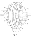
- FIGS. 1 a and 1 b show exemplary embodiments of a fluid pump with the cores of the first stator and the second stator axially aligned and axially offset, respectively,
- FIG. 2 shows an internal view of the fluid pump from FIG. 1 a
- FIG. 3 shows a sectional view through the fluid pump from FIG. 1 a
- FIG. 4 shows an oblique view of a side cover with inlet connecting elements
- FIG. 5 shows a further oblique view of the side cover from FIG. 4 .
- FIG. 6 shows a further embodiment of a side cover.
- FIGS. 1 a and 1 b show views of a fluid pump 1 in an assembled state, only differing from one another in that they illustrate the axial alignment or axial offset of the cores, respectively.
- An inner housing 2 is connected to a first and second side cover 3 , 4 preferably connected in a repeatedly detachable fashion. This can be done, for example, by means of a screw connection through holes 5 . These are distributed around the circumference, as a result of which a seal of a pump chamber in the inner housing 2 is made possible.
- the first and second side covers 3 , 4 have stator cores 6 which are each oriented running axially with respect to a rotor axle in the interior of the inner housing 2 .
- a winding is wrapped around each of the stators cores 6 , with the result that an electromagnetic field can be generated.
- a circuit board can be arranged on a cover 7 , which permits the respective windings and actuation means thereof to be connected.
- a liquid can be fed centrally via a feed line as a fluid inflow 8 centrally via the cover 7 .
- a fluid to be fed and discharged laterally.
- FIG. 2 shows in an exemplary embodiment an inner housing 2 with a combination rotor 9 which is arranged internally.
- the combination rotor rotates in the inner housing 2 .
- the combination rotor 9 can have recesses 10 , into which, for example, magnets or soft-magnetic elements can be inserted.
- a pump chamber 11 is located in an interior space of the combination rotor 9 .
- a gerotor 12 is located in the pump chamber.
- an impeller wheel pump, an impeller vane pump, a P rotor, a roller vane pump, a rotary vane pump or else a radial piston pump can also be arranged in the inner housing 2 .
- the respective pump wheel can either be a component of the combination rotor or can be arranged on an axle as in the case of the illustrated gerotor and can also rotate around it.
- the combination rotor 9 which is at the same time also the rotor of the electric motor, can have permanent magnets or else soft-magnetic elements, for example in the recesses 10 . It is therefore possible to form a permanently excited synchronous or brushless DC motor, abbreviated as BLDC, with permanent magnets as the axial flux electric motor, while, for example, a reluctance motor can be provided with an axial design, for example with soft-magnetic elements.
- a stator which is arranged on the rear side of the illustrated inner housing 2 because of the position can have a soft-magnetic material, for example, a Soft Magnetic Composite, abbreviated as SMC, or a combination of electrical sheets and SMC.
- An internal circumferential surface 13 of the inner housing 2 can be finely worked in such a way that it forms a seal with a side cover.
- the internal circumferential surface 13 can also have an additional seal which interacts in a seal-forming fashion with a complementary side of the side cover.
- FIG. 3 shows a sectional view of the fluid pump 1 in FIG. 1 a in a sectional view.
- the inner housing 2 together with the respective first and second side covers 3 , 4 , form a sealed-off, common housing 14 in which a pump wheel is driven by means of the combination rotor 9 .
- the illustration shows the disk-shaped geometry of the combination rotor 9 .
- the common housing 14 has the axially arranged fluid inflow 8 and a fluid outflow 15 arranged axially opposite the latter.
- the fluid inflow 8 can for this purpose conduct a fluid to the pump wheel in the second side cover by means of a lateral cutout, to the gerotor.
- the fluid outflow 15 can open into the pump chamber, again opposite, or as in some types of pump, offset with respect to the latter. It is also possible to conduct the fluid radially.
- FIG. 4 shows the second side cover 4 from FIG. 1 a with connecting elements 16 fitted thereon, from a lateral perspective.
- the connecting elements 16 permit, for example, the axial pump which is formed in this way to be screwed or attached in an installation space, for example an engine compartment of a passenger car.
- FIG. 5 shows the second side cover 4 from FIG. 1 a in a further perspective.
- Two junctions 17 are illustrated via which fluid can flow to or from the pump chamber.
- at least one nonmagnetic material is provided as the material.
- that region over which the combination rotor passes is manufactured from a nonmagnetic material.
- the nonmagnetic material is preferably also electrically nonconductive. It is therefore possible to use not only ceramic or plastic bus also a nonmagnetic metal.
- the side cover can be manufactured, for example, as an injection molded part or else as a sintered component. It is therefore also possible for different materials to be used.
- An embodiment provides that the side cover 4 is manufactured jointly together with the stator cores.
- a sintering method can be used, such as is known, for example, from DE 10 2009 042 598 A1 and JP H08-134509 A, to which reference is made in this respect within the scope of the disclosure.
- DE 10 2009 042 598 A1 and JP H08-134509 A disclose how, for example, identical or even different sintered materials can be produced together
- DE 10 2009 042 603 A1 discloses how prefabricated components can be introduced precisely into one component to be sintered. The latter is possible, for example, for manufacturing the stator with, for example, prefabricated stator cores made, for example, from sintered material, as in the case of the use of electric plates as soft-magnetic elements in the combination rotor for manufacturing a reluctance motor. Magnets can also be introduced in this way, wherein owing to the temperatures during sintering they can also preferably be firstly inserted after the sintering.
- FIG. 6 shows an exemplary embodiment of a second version of a further third side cover 18 .
- the third side cover 18 has, for example, soft magnetic poles 19 which are preferably manufactured from Soft Magnetic Composites. These can extend, for example as illustrated, as far as a surface and therefore also form an edge of the inner housing.
- Such a design has the advantage that the side cover can otherwise be manufactured from nonmagnetic material, for example from metallic powder by means of a sintering process.
- the proposed fluid pump can be used in different fields of application. Fluids of a wide variety of types such as Newtonian or Bingham fluid, as well as also gas can be transported.
- the use can comprise a wide variety of fields such as the chemical industry, the food stuff industry, use in machines and installations as well as also in the field of vehicles, aircraft and shipping.
- the fluids can comprise alkaline solutions or acids, can act corrosively and can be cooled or heated. The following examples are given only by way of example without being conclusive:
- An oil pump in an internal combustion engine circulation pump, for example in a coolant circuit or else in the field of heating; as a circulation pump, for example in drinking water systems; lubricant pump; as a hydraulic clutch actuator; in a fuel feed system; in the injection system in the region of the common rail in a gasoline or even diesel direct injection system; as an air-conditioning compressor; as a vacuum pump; as a servo pump, for example in the field of power steering systems; in a brake boosting system; in transmissions, in particular automatic transmissions, for example for the purpose of cooling, for maintaining a pressure, as a suction pump; in the field of aquariums; in PC and server cooling systems such as, for example, in a water cooling system; in medical technology, for example in a dialysis device, an infusion pump, an insulin pump; in an exhaust gas post-treatment system, for example for feeding in a urea; as a venting pump; in brake boosters, for filling pneumatic actuators; in active chassis; in windshield cleaning systems or headlight cleaning
Applications Claiming Priority (3)
| Application Number | Priority Date | Filing Date | Title |
|---|---|---|---|
| DE102015207748.9A DE102015207748A1 (de) | 2015-04-28 | 2015-04-28 | Fluidpumpe |
| DE102015207748.9 | 2015-04-28 | ||
| PCT/EP2016/059549 WO2016174164A1 (de) | 2015-04-28 | 2016-04-28 | Fluidpumpe |
Publications (2)
| Publication Number | Publication Date |
|---|---|
| US20180128268A1 US20180128268A1 (en) | 2018-05-10 |
| US11078904B2 true US11078904B2 (en) | 2021-08-03 |
Family
ID=55858768
Family Applications (1)
| Application Number | Title | Priority Date | Filing Date |
|---|---|---|---|
| US15/569,708 Active 2036-09-22 US11078904B2 (en) | 2015-04-28 | 2016-04-28 | Fluid pump |
Country Status (5)
| Country | Link |
|---|---|
| US (1) | US11078904B2 (zh) |
| EP (1) | EP3289221B1 (zh) |
| CN (1) | CN107787409B (zh) |
| DE (1) | DE102015207748A1 (zh) |
| WO (1) | WO2016174164A1 (zh) |
Families Citing this family (11)
| Publication number | Priority date | Publication date | Assignee | Title |
|---|---|---|---|---|
| EP3389063A1 (en) * | 2017-04-13 | 2018-10-17 | Comet AG | Variable vacuum capacitor and cooling method |
| DE102017222754A1 (de) | 2017-12-14 | 2019-06-19 | Magna Powertrain Bad Homburg GmbH | Gerotor Pumpe |
| DE102017223715A1 (de) | 2017-12-22 | 2019-06-27 | Magna Powertrain Bad Homburg GmbH | Gerotorpumpe und Verfahren zur Herstellung einer solchen |
| CN111306031A (zh) * | 2018-12-12 | 2020-06-19 | 杭州三花研究院有限公司 | 电动泵 |
| CN111725934B (zh) * | 2019-03-22 | 2024-04-23 | 广东德昌电机有限公司 | 流体泵 |
| FR3102510B1 (fr) * | 2019-10-25 | 2021-11-12 | Safran Helicopter Engines | Turbomachine munie d’une pompe électromagnétique à flux magnétique axial |
| FR3106625B1 (fr) * | 2020-01-27 | 2022-11-04 | Safran Helicopter Engines | Circuit d’alimentation en carburant d’un moteur d’aéronef |
| US20210320577A1 (en) | 2020-04-08 | 2021-10-14 | Halliburton Energy Services, Inc. | Axial Flux Submersible Electric Motor |
| EP3957823B1 (de) | 2020-08-20 | 2023-11-08 | GKN Sinter Metals Engineering GmbH | Pumpenanordnung |
| EP3957822B1 (de) | 2020-08-20 | 2023-12-13 | GKN Sinter Metals Engineering GmbH | Pumpenanordnung |
| CN216665906U (zh) * | 2021-11-17 | 2022-06-03 | 江门市君顺实业有限公司 | 一种模块化潜水齿轮泵及皂液器 |
Citations (6)
| Publication number | Priority date | Publication date | Assignee | Title |
|---|---|---|---|---|
| US5145329A (en) | 1990-06-29 | 1992-09-08 | Eaton Corporation | Homoplanar brushless electric gerotor |
| JPH08134509A (ja) | 1994-11-07 | 1996-05-28 | Honda Motor Co Ltd | 多層焼結部品用成形体の製造方法 |
| US6441530B1 (en) * | 2000-12-01 | 2002-08-27 | Petersen Technology Corporation | D.C. PM motor with a stator core assembly formed of pressure shaped processed ferromagnetic particles |
| WO2006021616A1 (en) | 2004-08-25 | 2006-03-02 | Axco-Motors Oy | Axial flux induction electric machine |
| WO2011035858A1 (de) | 2009-09-23 | 2011-03-31 | Gkn Sinter Metals Holding Gmbh | Verfahren zur herstellung eines verbundbauteils |
| US20120216654A1 (en) | 2009-09-23 | 2012-08-30 | Rainer Schmitt | Method for producing a green compact |
Family Cites Families (9)
| Publication number | Priority date | Publication date | Assignee | Title |
|---|---|---|---|---|
| CN1010337B (zh) * | 1985-05-16 | 1990-11-07 | 杨德贵 | 内切大圆弧卸荷叶片泵或马达 |
| US6074180A (en) * | 1996-05-03 | 2000-06-13 | Medquest Products, Inc. | Hybrid magnetically suspended and rotated centrifugal pumping apparatus and method |
| USH1966H1 (en) * | 1997-08-28 | 2001-06-05 | The United States Of America As Represented By The Secretary Of The Navy | Integrated motor/gear pump |
| DE10330434A1 (de) * | 2003-07-04 | 2005-02-03 | Jostra Ag | Zentrifugal-Pumpe |
| DE102007035239A1 (de) * | 2007-07-25 | 2009-01-29 | Joma-Hydromechanic Gmbh | Rotorpumpe |
| JP5564974B2 (ja) * | 2009-12-01 | 2014-08-06 | 株式会社ジェイテクト | 電動ポンプ及び電動ポンプの取付け構造 |
| JP5759740B2 (ja) * | 2011-02-15 | 2015-08-05 | 株式会社山田製作所 | 電動オイルポンプ |
| JP2013245611A (ja) * | 2012-05-25 | 2013-12-09 | Aisin Seiki Co Ltd | 電動オイルポンプ |
| DE102013205442A1 (de) * | 2013-03-27 | 2014-10-02 | Robert Bosch Gmbh | Pumpe mit Elektromotor |
-
2015
- 2015-04-28 DE DE102015207748.9A patent/DE102015207748A1/de not_active Ceased
-
2016
- 2016-04-28 EP EP16719085.9A patent/EP3289221B1/de active Active
- 2016-04-28 CN CN201680038361.2A patent/CN107787409B/zh active Active
- 2016-04-28 US US15/569,708 patent/US11078904B2/en active Active
- 2016-04-28 WO PCT/EP2016/059549 patent/WO2016174164A1/de active Application Filing
Patent Citations (6)
| Publication number | Priority date | Publication date | Assignee | Title |
|---|---|---|---|---|
| US5145329A (en) | 1990-06-29 | 1992-09-08 | Eaton Corporation | Homoplanar brushless electric gerotor |
| JPH08134509A (ja) | 1994-11-07 | 1996-05-28 | Honda Motor Co Ltd | 多層焼結部品用成形体の製造方法 |
| US6441530B1 (en) * | 2000-12-01 | 2002-08-27 | Petersen Technology Corporation | D.C. PM motor with a stator core assembly formed of pressure shaped processed ferromagnetic particles |
| WO2006021616A1 (en) | 2004-08-25 | 2006-03-02 | Axco-Motors Oy | Axial flux induction electric machine |
| WO2011035858A1 (de) | 2009-09-23 | 2011-03-31 | Gkn Sinter Metals Holding Gmbh | Verfahren zur herstellung eines verbundbauteils |
| US20120216654A1 (en) | 2009-09-23 | 2012-08-30 | Rainer Schmitt | Method for producing a green compact |
Non-Patent Citations (3)
| Title |
|---|
| Henry IV, et al., "Integrated Motor/Gear Pump" (US H1996 H), Jun. 2001 (Year: 2001). * |
| PCT International Search Report, PCT/EP2016/059549, dated Jul. 14, 2016. |
| US H1966 (H), Integrated Motor/Gear Pump, Inventor: John W. Henry IV, et al., Jun. 5, 2001. |
Also Published As
| Publication number | Publication date |
|---|---|
| EP3289221A1 (de) | 2018-03-07 |
| CN107787409B (zh) | 2020-07-03 |
| EP3289221B1 (de) | 2021-06-23 |
| CN107787409A (zh) | 2018-03-09 |
| WO2016174164A1 (de) | 2016-11-03 |
| US20180128268A1 (en) | 2018-05-10 |
| DE102015207748A1 (de) | 2016-11-03 |
Similar Documents
| Publication | Publication Date | Title |
|---|---|---|
| US11078904B2 (en) | Fluid pump | |
| US10018198B2 (en) | Pump arrangement having temperature control components | |
| US7074019B2 (en) | Rotor protector for wet-type rotor pump | |
| US20140271279A1 (en) | Electric fluid pump | |
| CN105406625A (zh) | 电动马达和转子 | |
| JP5880842B2 (ja) | 電動オイルポンプ装置 | |
| US20120164009A1 (en) | Electric pump unit | |
| US20070182259A1 (en) | Electric pump unit | |
| CN107923389B (zh) | 电动泵及其制造方法 | |
| CN103384771B (zh) | 汽车冷却剂泵 | |
| US11499548B2 (en) | Gerotor pump and method for producing same | |
| CN109075636B (zh) | 混合式转子模块的冷却 | |
| US20110002798A1 (en) | Fluid tank and fluid pump with exterior motor | |
| JP2011190763A (ja) | 回転式ポンプ | |
| JP2007205246A (ja) | ウォータポンプおよびハイブリッド車両 | |
| JP5282126B2 (ja) | モータポンプ装置 | |
| CN110311503B (zh) | 马达及车辆 | |
| CN111520322A (zh) | 内齿轮泵 | |
| CN110168224A (zh) | 电动油泵 | |
| JP5212147B2 (ja) | 電動ポンプユニット | |
| US20170363084A1 (en) | Compact, highly integrated, oil lubricated electric vacuum compressor | |
| KR20200141006A (ko) | 전기 기계용 샤프트 | |
| JP5772393B2 (ja) | 回転電機冷却構造及びその製造方法 | |
| JP2012026349A (ja) | 電動ポンプユニット | |
| JP6060488B2 (ja) | 電動ポンプユニット |
Legal Events
| Date | Code | Title | Description |
|---|---|---|---|
| FEPP | Fee payment procedure |
Free format text: ENTITY STATUS SET TO UNDISCOUNTED (ORIGINAL EVENT CODE: BIG.); ENTITY STATUS OF PATENT OWNER: LARGE ENTITY |
|
| AS | Assignment |
Owner name: GKN SINTER METALS ENGINEERING GMBH, GERMANY Free format text: ASSIGNMENT OF ASSIGNORS INTEREST;ASSIGNORS:BORNEMANN, NILS;TILLER, STEFAN;CASELLAS, ANTONIO;AND OTHERS;SIGNING DATES FROM 20171201 TO 20171203;REEL/FRAME:044875/0735 |
|
| STPP | Information on status: patent application and granting procedure in general |
Free format text: DOCKETED NEW CASE - READY FOR EXAMINATION |
|
| STPP | Information on status: patent application and granting procedure in general |
Free format text: NON FINAL ACTION MAILED |
|
| STPP | Information on status: patent application and granting procedure in general |
Free format text: RESPONSE TO NON-FINAL OFFICE ACTION ENTERED AND FORWARDED TO EXAMINER |
|
| STPP | Information on status: patent application and granting procedure in general |
Free format text: FINAL REJECTION MAILED |
|
| STPP | Information on status: patent application and granting procedure in general |
Free format text: ADVISORY ACTION MAILED |
|
| STPP | Information on status: patent application and granting procedure in general |
Free format text: DOCKETED NEW CASE - READY FOR EXAMINATION |
|
| STPP | Information on status: patent application and granting procedure in general |
Free format text: NON FINAL ACTION MAILED |
|
| STPP | Information on status: patent application and granting procedure in general |
Free format text: RESPONSE TO NON-FINAL OFFICE ACTION ENTERED AND FORWARDED TO EXAMINER |
|
| STPP | Information on status: patent application and granting procedure in general |
Free format text: NOTICE OF ALLOWANCE MAILED -- APPLICATION RECEIVED IN OFFICE OF PUBLICATIONS |
|
| STPP | Information on status: patent application and granting procedure in general |
Free format text: PUBLICATIONS -- ISSUE FEE PAYMENT RECEIVED |
|
| STPP | Information on status: patent application and granting procedure in general |
Free format text: PUBLICATIONS -- ISSUE FEE PAYMENT VERIFIED |
|
| STCF | Information on status: patent grant |
Free format text: PATENTED CASE |