US10981237B2 - Deburring tool for deburring transverse recesses that branch from a main borehole - Google Patents
Deburring tool for deburring transverse recesses that branch from a main borehole Download PDFInfo
- Publication number
- US10981237B2 US10981237B2 US16/275,080 US201916275080A US10981237B2 US 10981237 B2 US10981237 B2 US 10981237B2 US 201916275080 A US201916275080 A US 201916275080A US 10981237 B2 US10981237 B2 US 10981237B2
- Authority
- US
- United States
- Prior art keywords
- knife
- deburring
- recess
- cutting
- main borehole
- Prior art date
- Legal status (The legal status is an assumption and is not a legal conclusion. Google has not performed a legal analysis and makes no representation as to the accuracy of the status listed.)
- Active
Links
Images


Classifications
-
- B—PERFORMING OPERATIONS; TRANSPORTING
- B23—MACHINE TOOLS; METAL-WORKING NOT OTHERWISE PROVIDED FOR
- B23C—MILLING
- B23C3/00—Milling particular work; Special milling operations; Machines therefor
- B23C3/12—Trimming or finishing edges, e.g. deburring welded corners
-
- B—PERFORMING OPERATIONS; TRANSPORTING
- B23—MACHINE TOOLS; METAL-WORKING NOT OTHERWISE PROVIDED FOR
- B23D—PLANING; SLOTTING; SHEARING; BROACHING; SAWING; FILING; SCRAPING; LIKE OPERATIONS FOR WORKING METAL BY REMOVING MATERIAL, NOT OTHERWISE PROVIDED FOR
- B23D79/00—Methods, machines, or devices not covered elsewhere, for working metal by removal of material
- B23D79/02—Machines or devices for scraping
- B23D79/04—Machines or devices for scraping with rotating cutting-tool, e.g. for smoothing linings of bearings
-
- B—PERFORMING OPERATIONS; TRANSPORTING
- B23—MACHINE TOOLS; METAL-WORKING NOT OTHERWISE PROVIDED FOR
- B23B—TURNING; BORING
- B23B51/00—Tools for drilling machines
- B23B51/10—Bits for countersinking
- B23B51/101—Deburring tools
-
- B—PERFORMING OPERATIONS; TRANSPORTING
- B23—MACHINE TOOLS; METAL-WORKING NOT OTHERWISE PROVIDED FOR
- B23B—TURNING; BORING
- B23B51/00—Tools for drilling machines
- B23B51/10—Bits for countersinking
- B23B51/105—Deburring or countersinking of radial holes
-
- B—PERFORMING OPERATIONS; TRANSPORTING
- B23—MACHINE TOOLS; METAL-WORKING NOT OTHERWISE PROVIDED FOR
- B23C—MILLING
- B23C5/00—Milling-cutters
- B23C5/02—Milling-cutters characterised by the shape of the cutter
-
- B—PERFORMING OPERATIONS; TRANSPORTING
- B23—MACHINE TOOLS; METAL-WORKING NOT OTHERWISE PROVIDED FOR
- B23C—MILLING
- B23C5/00—Milling-cutters
- B23C5/16—Milling-cutters characterised by physical features other than shape
- B23C5/20—Milling-cutters characterised by physical features other than shape with removable cutter bits or teeth or cutting inserts
- B23C5/22—Securing arrangements for bits or teeth or cutting inserts
- B23C5/24—Securing arrangements for bits or teeth or cutting inserts adjustable
-
- B—PERFORMING OPERATIONS; TRANSPORTING
- B23—MACHINE TOOLS; METAL-WORKING NOT OTHERWISE PROVIDED FOR
- B23B—TURNING; BORING
- B23B2220/00—Details of turning, boring or drilling processes
- B23B2220/08—Deburring
-
- B—PERFORMING OPERATIONS; TRANSPORTING
- B23—MACHINE TOOLS; METAL-WORKING NOT OTHERWISE PROVIDED FOR
- B23B—TURNING; BORING
- B23B2251/00—Details of tools for drilling machines
- B23B2251/14—Configuration of the cutting part, i.e. the main cutting edges
-
- B—PERFORMING OPERATIONS; TRANSPORTING
- B23—MACHINE TOOLS; METAL-WORKING NOT OTHERWISE PROVIDED FOR
- B23C—MILLING
- B23C2210/00—Details of milling cutters
- B23C2210/04—Angles
- B23C2210/0407—Cutting angles
-
- B—PERFORMING OPERATIONS; TRANSPORTING
- B23—MACHINE TOOLS; METAL-WORKING NOT OTHERWISE PROVIDED FOR
- B23C—MILLING
- B23C2210/00—Details of milling cutters
- B23C2210/08—Side or top views of the cutting edge
- B23C2210/084—Curved cutting edges
-
- B—PERFORMING OPERATIONS; TRANSPORTING
- B23—MACHINE TOOLS; METAL-WORKING NOT OTHERWISE PROVIDED FOR
- B23C—MILLING
- B23C2210/00—Details of milling cutters
- B23C2210/12—Cross section of the cutting edge
-
- B—PERFORMING OPERATIONS; TRANSPORTING
- B23—MACHINE TOOLS; METAL-WORKING NOT OTHERWISE PROVIDED FOR
- B23C—MILLING
- B23C2220/00—Details of milling processes
- B23C2220/20—Deburring
-
- B—PERFORMING OPERATIONS; TRANSPORTING
- B23—MACHINE TOOLS; METAL-WORKING NOT OTHERWISE PROVIDED FOR
- B23C—MILLING
- B23C2245/00—Details of adjusting inserts or bits in the milling cutter
Definitions
- the invention relates to a deburring tool for deburring transverse recesses in a main borehole according to the preamble of patent claim 1 .
- such a deburring tool has become known, which is characterized in that a first cutting segment of the cutting edge and a second cutting segment of the cutting edge are present, which are arranged on the particular end areas of the cutting edge, the first cutting segment having a first wedge angle and the second cutting segment having a second wedge angle and the two wedge angles being arranged to be spatially offset to each other.
- the known debarring tool could also be operated in rightward and leftward passes to conduct a deburring.
- a turning driven shaft is present with a movable cutting body arrangement held by a radial groove on the shaft, with at least two wedge-shaped cutters placed opposite each other, wherein the cutters arranged on separate cutter bodies are guided in spring-loaded fashion in the radial direction in a knife window of the shaft.
- Such a deburring tool is only suitable for deburring of boreholes in a main borehole, and not for deburring of the circumferential edges of transverse recesses running transverse to the main borehole.
- the cutters act only one rotational direction (as a rule rightward) and do not permit the transverse recess edges to be deburred in circumferential fashion.
- the cutting edges are not overall configured to be convex and arch-shaped, which prevents a paring cutting with simultaneous forcing of the knife out of the transverse recess.
- the object based on WO 2016/135283 A1, is to further develop a deburring tool of the type mentioned initially, so that the quality of deburring in the recess edges of a transverse recess, which intersects the main borehole, is better, and that deburring is faster.
- the invention is characterized by the technical teaching of claim 1 .
- a preferred embodiment of the invention consists in the knife consisting of two cutting edges lying opposite in the rotational direction, which act with equal cutting for the right and left passes, with the one cutting edge configured for the rightward pass and the other cutting edge for the leftward pass, and that the two cutters with their cutting edges are set at a slant and have an arch shape with their cutting edges in an angle between 0° and 90°, but preferably between 5° and 45° to the tool axis, and thus to the longitudinal axis of the main borehole.
- continuous means that the particular cutting edge extends with constantly convexity and is arch-shaped over the entire cutting surface of the cutting knife—preferably over its side wall—and is not segmented.
- a roughly central vertex point or a vertex zone is formed, to knock off the metallic burrs on the circumferential edge of the transverse recess according to the invention at a specific place with a specific angular rotation of the shaft.
- the arch-shaped convex cutting edges configured to be continuous throughout, make it possible for the knife to run along continuously on the edges of the transverse recess and remove the burrs present in a specific circumferential area of the transverse recess due to a short angular turning motion of the shaft, with a paring cut.
- the tool shaft is driven to turn and moves centrically, or also eccentrically in an axial direction in the central axis of the main borehole with a preferable forward speed of 600 mm per minute.
- the shaft turns continuously and rotates at a rotational rate in the range between 1 r.p.m. to 1000 r.p.m.
- Such deburring tools are preferably used for the deburring of transverse recesses on the inner walls of the main borehole for diameters of main boreholes ranging between 4 mm and 30 mm.
- the axial length of such a deburring tool ranges between 50 mm and 350 mm.
- the one knife or the plurality of knives radially project between 0.25 mm and 0.50 mm over the bore diameter of the main borehole and beyond the outer diameter of the knife window, and, upon being inserted into the main borehole by this amount, are spring-loaded and pressed back into the particular knife window of the deburring tool, to then, upon reaching a transverse recess in the inner wall of the main borehole, be pressed radially outward from the knife window, to thereby deburr the circumferential edges of the transverse recess. Consequently, the size data between 0.25 and 0.5 mm are the radial operating stroke of one or more knives.
- the tool shaft moves further with a simultaneous axial forward shift by a second short angular turning motion of the shaft and thus the deburring knives lift away from the edge of the transverse recess and move with a further turning motion of the shaft at another location on the circumference of the main borehole wall into the transverse recess, in order at this additional location on the edge of the transverse recess to remove the burrs present there in a second deburring action.
- the invention is not drawn upon the arrangement of a first and second wedge angle as per WO 2016/135283 A1, and likewise not on a clearance angle lying between them, because the control surface as per the invention in an ideal case must be oriented by 90° to the tool axis, so that the cutting edges perform cutting actions continuously for the right and left passes, simultaneously over the entire arch.
- the method of deburring proceeding from the main borehole obviates the clearance angle on the knife, as known from prior art, because the clearance angle from positioning of the cutting edge and the deburring contour arise corresponding to the cutting angle 25 .
- a third cutting segment is also done away with.
- the cutting edge of the knife is configured to be continuous and constant, and is not subdivided into two cutting edges that are spatially displaced from each other.
- the prior-art cutting edges that are spatially displaced from each other presuppose a first deburring in the leftward pass and a second deburring in the rightward pass, which is just what the invention avoids.
- the two diametrically opposite cutting edges cut simultaneously both in the rightward and in the leftward pass.
- FIG. 1 a first embodiment, of how burrs can be removed outward from a main borehole
- FIG. 2 a second embodiment
- FIG. 3 a third embodiment
- FIG. 4 a fourth embodiment
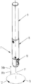
- FIG. 5 a perspective view of the deburring tool as per the invention
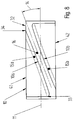
- FIG. 6 a section through the deburring tool of FIG. 5
- FIG. 7 the perspective depiction of the deburring knife
- FIG. 8 the view of FIG. 7 turned by 90° with a top down view of the cutting edge
- FIG. 9 a view of the deburring knife turned by a further 90°
- FIG. 10 a view turned vis-à-vis FIG. 9 , to make clear the shaving angle
- FIG. 11 a spatial perspective depiction of the cutting knife with an additional feature
- FIG. 12 an embodiment version of the tool with two deburring knives parallel to each other
- FIG. 13 an embodiment altered from FIG. 12 , in which two individual knives are arranged to lie serially over each other
- FIG. 14 a perspective drawing of the deburring process of the deburring knife when deburring the recess edges of a transverse recess
- FIG. 15 an embodiment altered from FIG. 14 in which, instead of a cylindrical borehole of FIG. 14 , now an elongated recess is deburred
- FIG. 16 a view of a transverse recess of a work piece, and schematically a knife arranged in a main borehole from prior art, for example as per WO 2016/135283 A1
- FIG. 17 a view of a transverse recess of the work piece and schematically a knife arranged in the main borehole as per the invention.
- Any recesses 3 are deburred in the area of their recess edges 4 with the main borehole 2 in work piece 1 along main borehole 2 , which intersect or penetrate in any form and angle.
- the deburring tool 7 operates through main borehole 2 , i.e. the knife 10 operates proceeding outward from main borehole 2 into the recesses 3 .
- the main feature of this deburring task is that the recess edges 4 are always arranged on the cylinder of main borehole 2 and intersect same, and thereby are always reachable for deburring tool 7 operating through main borehole 2 .
- main boreholes 2 into which a plurality of lateral, so-called auxiliary boreholes 3 or auxiliary recesses penetrate.
- auxiliary boreholes 3 are, for example, valve housings, drive and output shafts, and many others.
- the advantage of this tool concept is that operating through main borehole 2 , all of the recesses 3 adjoining this main borehole can be deburred with the forward motion of the deburring tool in series with the rotationally driven deburring tool 7 .
- FIG. 1 Examples of such recesses are shown in FIG. 1 :
- the recesses 3 can be configured in the form of transverse recesses, whose recess axis 3 a runs at an angle 5 of 90° to main borehole axis 2 a and penetrates through main borehole 2 . There also are recesses 3 d that run offset to main borehole axis 2 a . There are also recesses 3 d which run offset to main borehole axis 2 a . Likewise recesses 3 c , which completely penetrate main borehole 2 in offset fashion, thus extending out via them.
- FIG. 2 Further examples of the possible shapes of recesses re shown in FIG. 2 :
- Additional recesses 3 c can be configured in the form of elongated holes, the recess axes 3 a of which lie at an angle of 5 to 90° to main borehole axis 2 a .
- elongated hole recesses 3 f the recess position 3 b of which run at any angle 6 up to parallel to main borehole axis 2 a , are present.
- FIG. 3 Further examples of the possible shapes of recesses are shown in FIG. 3 :
- the recesses 3 g can be configured in the form of transverse boreholes, the recess axes 3 a of which run at any angle 5 to main borehole axis 2 a down to the parallel, and penetrate through main borehole 2 .
- FIG. 4 Further examples of the possible shapes of recesses are shown in FIG. 4 :
- the recesses 3 h can be in the form of milled grooves which penetrate main borehole 2 at an angle of from 90° down to being parallel.
- Further recesses 3 i can be configured in the form of slot grooves, whose straight-running longitudinal axes are parallel to main borehole 2 or lie at any angle.
- Two cutting edges 10 a and 10 b formed from two opposite chipping depressions 15 a ; 15 b and an arch-shaped, limiting control surface 16 .
- the orientation 17 of control surface 16 is orthogonal to tool axis 11 . 4.
- a first possible variant the two cutting edges 10 a and 10 b lying opposite in the rotational direction, acting for rightward 12 and leftward 13 passes are set at a slant 14 of 0° to 5° to tool axis 11 . 5.
- a glide surface 21 is attached at the vertex point of control surface 16 and has a radius 22 smaller equal to half the diameter of main borehole 2 . By this mean the borehole wall is protected from texturing by the cutting edges at the vertex point.
- the distance between the two opposite chipping depressions 15 a and 15 b preferably is 0.2 mm to 1 mm. 8.
- the chipping angle 20 of the two opposite chipping depressions 15 a and 15 b preferably has an angle between ⁇ 20° and 20°.
- the arch radius 19 of control surface 16 is dimensioned so that the cutting angle 25 is at most 45°, so that the particular acting cutting edge 10 a or 10 b inserts knife 10 along recess edge 4 radially in direction 24 into knife window 27 .
- the vertex point of knife 10 lying in the rebound position projects over the diameter of main borehole 2 maximally radially by the amount of arch height 18 of control surface 16 .
- the invention also claims a method for deburring of recesses 3 of any shape along main borehole 2 with longitudinal-side passage of the main borehole at first only in a rightward pass 12 and second only in a leftward pass 13 .
- the invention claims a method for deburring of recesses 3 of any shape along main borehole 2 with longitudinal-side passage of the main borehole initially in a leftward pass 13 and then in a rightward pass 12 or vice versa, initially in a rightward pass 12 and then following in a leftward pass 13 .
- the cutting motion 23 acting for paring shifts knife 10 radially in the direction 24 into knife window 27 and deburrs its recess edges.
- the two opposite cutting edges 10 a and 10 b remove the burr from both sides, proceeding from the center of recess 3 , 3 a - i in the direction of recess edges 4 .
- the two opposite cutting edges 10 a and 10 b remove the burr from both sides, proceeding from outside the recess edges 4 in the direction of the recess center.
- FIG. 5 shows a perspective embodiment of a first embodiment of a deburring tool, in which on a shaft 9 driven to turn, which can be driven to turn as desired in arrow directions 12 and 13 , a base body 8 is attached, on the forward front end of which a knife window (see FIG. 6 ) is present, which is radially oriented to tool axis 11 .
- invention-specific knife 10 is arranged, which as per FIG. 6 is able to be extracted and inserted radially in spring-loaded fashion in arrow direction 29 from knife window 26 .
- retaining or pretensioning means can also be used for knife 10 .
- the knife can be held with the aid of a compressed fluid or an elastomer compression spring in the initial position depicted in FIG. 6 , and brought against the force of the elastomer compression spring or of the compressed fluid or some other pretensioning medium into the working setting, as depicted in FIGS. 5 and 6 .
- knife 10 is held in spring-loaded fashion by the pretensioning means in its cutting operating setting as per FIGS. 5 and 6 , and upon entering main borehole 2 , 2 a , yields back by spring force, and upon entry into a transverse recess 3 , 3 a - 3 i which adjoins the wall of main borehole 2 , 2 a under the force of the pretensioning means is shifted into the active, cutting operating position shown in FIGS. 5 and 6 .
- Cylindrical compression spring 28 can also be replaced by other types of springs. Instead, for example, spiral springs, cup springs or any hydraulic or pneumatic pretensioning means can be used.
- deburring knife 10 upon passing through main borehole 2 and upon making initial starting entry into transverse recess 3 , engages the start of recess edge 4 , and executes a paring cut due to the invention-specific slanted setting of the cutting edges of knife 10 , through which, due to the axial forward feed of deburring tool 7 with simultaneous rotation, there is progressive continuous deburring of the recess edges in the particular transverse recess.
- deburring tool 7 is inserted in a rightward pass as per turning direction 12 into main borehole 2 , then knife 10 is engaged in its operational setting out of knife window 26 in arrow direction 29 to the right on both sides of recess edge 4 .
- the knife spring-loaded, engages on the inner diameter of main borehole 2 and as soon as it gets to the area of transverse recess 3 , the burr found there on the edge is knocked off. Thereafter, knife 10 drops into the transverse recess and is fed still farther radially out of knife window 26 , until, with its slanted cutting surface it runs up to the opposite edge of the transverse recess, and then is again pushed back against the spring force of the driving medium, for example spring 28 , into knife window 26 , and during this pushback motion it also pares away the burr on the transverse recess on the opposite side of the transverse recess.
- the driving medium for example spring 28
- deburring tool 7 is driven in a leftward pass in turning direction 13 , the opposite process occurs, namely that instead of knocking off the one side of the burr on the recess edge of transverse recess 3 , now the other side is knocked off, and the opposite side of the recess edge in transverse recess 3 is now removed with a paring cut.
- the knife cuts as per the invention on both sides and does not have a clearance angle on the one side, and a cutting surface on the other side, as in the prior art.
- the disadvantage is that the knife, which is provided for deburring, enters with this clearance angle into the transverse recess and there carries out no deburring, but rather simply pushes the burr found there into the transverse recess, without removing it.
- FIG. 7 depicts such an invention-specific knife 10 , in which the perspective view of the control recess 30 is shown, into which control bolt 27 , shown in FIGS. 5 and 6 , engages, and pretensions the entire knife 10 in arrow direction 31 .
- knife 10 Due to this pretensioning, knife 10 is held in its active operational position as per FIGS. 5 and 6 , and is pushed back by spring loading into its inactive setting in knife window 26 , when one of the cutting edges 10 a or 10 b reaches recess edge 4 of transverse recess 3 , 3 a - 3 i.
- cutting edges 10 a , 10 b extend in uninterrupted fashion, slanted and always progressing over the side edge of knife 10 , and are neither segmented, nor interrupted nor configured to be discontinuous.
- cutting edges 10 a , 10 b do not extend over the entire side surface of knife 10 , but rather, due to reasons of production technology, they start at an edge-side position 33 , extend with arch shape, parallel to each other, and at a mutual distance over the entire side surface of knife 10 , and go to the opposite, edge-side position 34 , which ends shortly before the end of the knife body and there makes a transition into a concluding edge 32 that is not more precisely defined.
- both cutting edges 10 a and 10 b are part of a control surface 16 , which as per FIG. 9 has a bead or arch progression, wherein on the far side and near side of control surface 16 , the two cutting edges 10 a , 10 b are arranged in specular symmetry to each other as per FIG. 10 .
- the two cutting edges 10 a , 10 b are part of a convex control surface 16 that projects out with arch shape, as is perceived in FIG. 9 , and the ground section of cutting edges 10 a , 10 b is perpendicular to the longitudinal axis and axis of symmetry of control surface 16 , i.e., this is a straight ground section, which is also designated as a cylindrical ground section.
- rear side 35 is configured with the same identical arrangement of cutting edges 10 a and 10 b as per FIG. 9 , so that the result is a fully symmetrical (dual) knife 10 relative to tool axis 11 , however then control recess 30 , which in FIG. 9 is shown on the right side of the body of knife 10 , also could be arranged on the left front side 36 , to produce a turning knife, which, after turning by 180° as per FIG. 9 , could then cut with the opposite cutting arrangement on rear side 35 .
- the simple knife 10 describe here can also be configured as a double knife, which, after wear occurs on cutting edges 10 a and 10 b on the front side, can be turned by 180 degrees, so that the additional cutting edges 10 a , 10 b attached on the rear side can be used.
- the invention makes provision for only a single cutting side 37 , as depicted in FIG. 9 , and in a variant of the embodiment not depicted in further detail, it is possible that this cutting side 37 could be arranged in specular symmetry to tool axis 11 on the opposite rear side 35 .
- the cutting angle 14 was zero degrees, i.e. it extends parallel to the tool axis, which resulted in the impacting cut named previously in the introduction to the specification, which is to be avoided according to the invention.
- deburring tool 7 as per FIG. 5 , both in feed direction 38 a forward, and in reverse direction 38 b , performs a cutting action.
- deburring tool 7 When deburring tool 7 has then run through main borehole 2 , it switches into a leftward pass (arrow direction 13 ), and knife 10 is withdrawn in the opposite direction to arrow direction 38 a , namely in arrow direction 38 b , out of main borehole 2 .
- transverse recesses 3 are likewise deburred, if deburring tool 7 is withdrawn in arrow direction 38 b in a leftward pass from main borehole 2 .
- a differing deburring action occurs only with the transverse borehole that adjoins the main borehole and intersects same, depending on whether the knife is drawn through borehole 2 in a rightward pass 12 in the forwards direction as per 38 a or in leftwards motion 13 in the rear direction in 38 b.
- deburring action occurs on all of the transverse recesses 3 , 3 a - i adjoining onto main borehole 2 , independent of whether these transverse recesses 3 , 3 a - i adjoin main borehole 2 on the left or right side, or not.
- control surface 16 and cutting edges 10 a and 10 b be equally long and symmetrically configured.
- cutting radius 40 forms a constant arch surface of control surface 16 and of adjoining cutting edges 10 a and 10 b immediately parallel and symmetrical thereto.
- the embodiment shown is partially circular cutting edges 10 a and 10 b with a certain cutting radius 40 , to which the invention is not limited, however.
- Cutting edges 10 a and 10 b can, for example, also be configured as ovals or parabolas.
- the height of the arch 18 must ensure that knife 10 with its cutting part, namely with cutting edges 10 a and 10 b , as well as with non-cutting control surface 16 lying in between, can actively be deployed from knife window 26 , without lateral, non-cutting parts of knife 10 colliding with parts of the work piece.
- FIG. 10 shows the situation as per FIGS. 7 to 9 in another view, where it can easily be perceived that roughly arch-like cutting edges 10 a and 10 b lie opposite each other in specular symmetry, in fact on the other side of tool axis 11 and lying between the convex arch of control surface 16 .
- control surface 16 projects out radially over cutting side 37 , and the two cutting edges 10 a and 10 b are configured to be specularly symmetric and central to the center point of control surface 16 .
- the invention is not limited to a specularly symmetric configuration of the two cutting edges 10 a and 10 b lying opposite relative to tool axis 11 .
- cutting edge 10 a has a greater distance to tool axis 11 than cutting edge 10 b , comparatively.
- cutting edge 10 a has a different cutting radius than cutting edge 10 b , comparatively.
- the two cutting edges 10 a and 10 b be configured to be specularly symmetric in regard to central convex control surface 16 .
- a vertex surface 41 is depicted as a straight surface of control surface 16 .
- This vertex surface 41 is a flat curve or a flat surface, which in fact could also be configured concave.
- first contact surface of knife 10 is in main borehole 2 and thereafter in transverse recess 3 extending transverse thereto at position 33 or 34 .
- non-cutting final edge 32 could adjoin the inner circumference of the borehole, but this has no cutting function whatever.
- Final edge 32 could, however, perform a control function, in that the knife in arrow direction 29 is pressed into knife window 26 in spring-loaded fashion.
- Vertex point 39 of control surface 16 does not touch the inner circumference of main borehole 2 , because this is an arch-shaped borehole.
- a chip slope 20 is defined with reference symbol 20 .
- Chip slope 20 is the angle of the chip surface in the direction of cutting edge 10 a and 10 b.
- Chip slope 20 is important for cutting various materials, because it is with it that chip removal of the material produced during cutting is determined. This also determines the edge life of the tool.
- chip guidance steps are chip guidance steps.
- control surface 16 is at an angle 17 of 90° for example to tool axis 11 and to the knife axis, because this ensures that knife 10 cuts uniformly in the leftward and rightward passes.
- FIG. 11 shows an altered embodiment, namely in such a way that control surface 16 penetrates fully through, but in the central area of control surface 16 an additional gliding surface 21 is arranged.
- vertex point 39 which carries out a cutting action in the area of the particular recess edge 4 in the area of transverse recess 3 .
- a non-cutting gliding surface 21 is arranged.
- gliding surface 21 interrupts the arch shape of the otherwise constant continuous cutting edges 10 a and 10 b , because at this vertex point 9 a non-cutting gliding surface 21 is present, which penetrates both the control surface 16 and the arched shape of cutting edges 10 a and 10 b.
- the two non-cutting vertex points 39 a and 39 b are inscribed, and according to this embodiment, they are displaced back, so that they are outside the cutting area of cutting edges 10 a and 10 b.
- FIGS. 12 and 13 show further embodiments of the invention, with varied cutting knives 10 , 10 ′, 10 ′′ depicted in these figures, wherein knife 10 depicted there is able to be configured according to all the embodiments that were previously described.
- FIG. 12 depicts a first knife 10 ′, which is arranged back to back with a second knife 10 ′′ in knife window 26 .
- first knife 10 ′ which is arranged back to back with a second knife 10 ′′ in knife window 26 .
- second knife 10 ′′ in knife window 26 .
- the two slanted cutting edges 10 a and 10 b are arranged parallel to each other and are divided into two different knives.
- the two knives 10 ′ and 10 ′′ are impinged on by different control bolts 27 with different compression springs 28 , and thus, separate from each other and independent of each other, can be slid out of knife window 26 and into knife window 26 , under the load of differing compression springs 28 .
- compression springs 28 parallel to each other are configured to be identical, with the invention not being limited to this, however.
- FIG. 13 depicts that the previously described knives 10 can be arranged in all the versions, i.e. thus also in the tandem arrangement of knives 10 ′ and 10 ′′ lying axially one above the other at a mutual interval 43 .
- the front knife 10 ′′′ moves ahead in main borehole 2 and already has deburred a part of transverse recesses 3 , 3 a - i terminating in main borehole 2
- rear knife 10 ′′′′ now undertakes the refined work of deburring of recess edges 4 in the area of transverse recesses 3 , 3 a - i.
- knives 10 , 10 ′ 10 ′′, 10 ′′′ 10 ′′′′ are arranged to be spring-loaded by various, separate control bolts and compression springs 28 in base body 8 of deburring tool 7 .
- the invention however is not limited to this.
- cutting angle 14 does not have a positive value, as FIG. 7 depicts, but rather a negative value that is below tool axis 11 .
- FIG. 14 shows the deburring of a cylindrical transverse recess. It is shown that arch-shaped cutting edges 10 a , 10 b first engage into the start of transverse recess 3 with forward feed of deburring tool 7 .
- knife 10 makes progressive paring cuts in arrow direction 23 between positions 44 and 45 along a contact line.
- the contact points at positions 44 and 45 run toward each other, and in particular in arrow directions 23 , until at arrow direction 24 cutting knife 10 runs out of transverse recess 3 first at vertex point 39 .
- FIG. 14 now shows that there is a certain radial distance between arch radius 19 of the control surface and recess edge 4 of transverse recess 3 to be deburred.
- Cutting angle 25 may not be too small; it thus must be an angle that is greater than 0, because otherwise there would not be a paring cut of cutting edges 10 a and 10 b along recess edge 4 .
- FIG. 15 An altered embodiment of FIG. 14 is depicted in FIG. 15 , where the same reference symbols are applied for the same conditions. For the sake of simplification, however, not all reference symbols are drawn in the same parts.
- FIG. 15 shows that instead of a cylindrical transverse recess 3 , now a milled recess or an elongated hole can be deburred in the same way.
- This is an elongated hole, the longitudinal axis of which is parallel to main borehole 2 and to main borehole axis 2 a , and thus also parallel to tool axis 11 .
- the front cutting edge 10 a is seen in a side view, and it covers cutting edge 10 b that lies behind, with the two cutting edges 10 a and 10 b being spatially separated from each other by control surface 16 .
- position 44 advances forward in the longitudinal direction, i.e. in the arrow direction of cutting motion 23 .
- knife 10 with its cutting edges 10 a and 10 b , from the area of position 44 , cuts up to vertex point 39 and then with continued turning, for example in a rightward pass 12 , it leaves recess edge 4 and with the forward feed of deburring tool 7 in feed direction 38 a , 38 b , it again enters recess 3 , but at another place, for example that the vertex point, now progressing, is in setting 39 ′ and then likewise a deburring action takes place at the margin of recess edge 4 , as long as, as with the next rotation of the knife, again vertex point 39 ′ has migrated leftward, to thus deburr the recess edge 4 in sequence and continuously.
- deburring action occurs approximately from position 44 to vertex point 39 , before knife 10 leaves the margin of recess edge 4 and, with another revolution of the tool in arrow direction 12 , enters into transverse recess 3 and, for example, at position 39 ′, another deburring action occurs up to position 39 ′.
- deburring tool 7 With the axial forward feed of deburring tool 7 , sequentially the surfaces of recess edge 4 are deburred in arrow direction 23 , as this is depicted in arrow direction 23 in FIG. 15 .
- both edges 47 , 48 of recess edge 4 are also deburred, only on front edge 47 another paring deburring action occurs in comparison to the knocking-off action on the rear edge 48 .
- deburring tool 7 is run in a leftward pass (arrow direction 13 ), the deburring action that previously was described using front edge 47 with paring action, now occurs on the opposite rear side 48 , and on front side 47 , the other deburring action, of a knockoff nature, takes place.
- FIG. 16 shows a view of a transverse recess 3 of a work piece 1 and, schematically, a knife 110 arranged in main borehole 2 as per the prior art, for example according to WO 2016/135283 A1.
- Knife 110 is part of a deburring tool (not shown) which is able to be run in forward feed direction 38 a and also in reverse direction 38 b , within main borehole 2 .
- the deburring tool and knife 110 arranged thereon can be run in a rightward pass 12 and leftward pass 13 , with knife 110 rotating in the rotary directions of rightward pass 12 and leftward pass 12 about the mid-longitudinal axis of main borehole 2 .
- Knife 110 comprises two cutting edges 110 a and 110 b arranged next to each other. Due to the clearance angles 50 a and 50 b between cutting edge 110 a and cutting edge 110 b , in forward feed direction 38 a and reverse direction 38 b of knife 110 , only one cutting edge 110 a or 110 b cuts, both in rightward pass 12 and leftward pass 13 of knife 110 .
- knife 110 is run in reverse direction 38 b , i.e. with a reverse stroke motion, in rightward pass 12 , then reverse cutting edge 110 a cuts and covers the depicted effective area 149 b . But if knife 110 is run in reverse stroke 38 b in leftward pass 13 , the other cutting edge 110 b , due to clearance angle 50 b , has no function and no cutting action occurs.
- FIG. 17 shows a head on view of transverse recess 3 of work piece 1 and, schematically, a knife 10 as per the invention, arranged in main borehole 2 .
- Cutting edges 10 a , 10 b according to the invention have no clearance angle, thus it is possible that the two cutting edges 10 a , 10 b lying next to each other, can perform a cutting action in forward stroke 38 a in rightward pass 12 and in leftward pass 13 , and also in rearward stroke 38 b in rightward pass 12 and in leftward pass 13 .
- Cutting edge 10 b cuts in leftward pass 13 both in forward motion 38 a and in rearward motion 38 b .
- Cutting edge 10 a cuts in rightward pass 12 both in forward motion 38 a and in rearward motion 38 b of knife 10 .
- Cutting edges 10 a and 10 b consequently have an effective area 49 a and 49 b , which covers the entire edge of the transverse recess. Thus the entire edge of the transverse recess is deburred.
Landscapes
- Engineering & Computer Science (AREA)
- Mechanical Engineering (AREA)
- Physics & Mathematics (AREA)
- Optics & Photonics (AREA)
- Milling, Broaching, Filing, Reaming, And Others (AREA)
- Milling Processes (AREA)
- Drilling Tools (AREA)
Applications Claiming Priority (3)
| Application Number | Priority Date | Filing Date | Title |
|---|---|---|---|
| EP18157116 | 2018-02-16 | ||
| EP18157116.7A EP3527312B1 (de) | 2018-02-16 | 2018-02-16 | Entgratwerkzeug zur entgratung von querausnehmungen, die von einer hauptbohrung ausgehen |
| EP18157116.7 | 2018-02-16 |
Publications (2)
| Publication Number | Publication Date |
|---|---|
| US20190255627A1 US20190255627A1 (en) | 2019-08-22 |
| US10981237B2 true US10981237B2 (en) | 2021-04-20 |
Family
ID=61231115
Family Applications (1)
| Application Number | Title | Priority Date | Filing Date |
|---|---|---|---|
| US16/275,080 Active US10981237B2 (en) | 2018-02-16 | 2019-02-13 | Deburring tool for deburring transverse recesses that branch from a main borehole |
Country Status (8)
| Country | Link |
|---|---|
| US (1) | US10981237B2 (es) |
| EP (1) | EP3527312B1 (es) |
| JP (1) | JP6872573B2 (es) |
| KR (1) | KR102189788B1 (es) |
| CN (1) | CN110153505B (es) |
| CA (1) | CA3033782C (es) |
| ES (1) | ES2944591T3 (es) |
| MX (1) | MX2019001890A (es) |
Families Citing this family (8)
| Publication number | Priority date | Publication date | Assignee | Title |
|---|---|---|---|---|
| KR102934870B1 (ko) | 2020-06-17 | 2026-03-09 | 현대자동차주식회사 | 디버링 툴 |
| CN111822790A (zh) * | 2020-07-17 | 2020-10-27 | 大连理工大学 | 一种深长管相贯处去毛刺专用装置及其刀具 |
| CN113441766B (zh) * | 2021-07-12 | 2022-05-13 | 爱柯迪股份有限公司 | 影像壳体180度翻转机构及去毛刺设备 |
| CN113714570B (zh) * | 2021-09-26 | 2022-07-26 | 一汽解放汽车有限公司 | 一种双向反刮刀 |
| CN115846772B (zh) * | 2022-12-12 | 2025-09-05 | 北京天玛智控科技股份有限公司 | 内孔去毛刺装置和用于交叉孔轮廓的去毛刺方法 |
| CN118204565A (zh) * | 2024-02-22 | 2024-06-18 | 江苏广大鑫盛精密智造有限公司 | 一种大型轴体孔位边缘倒角设备 |
| CN118527713B (zh) * | 2024-04-29 | 2025-07-08 | 株洲钻石切削刀具股份有限公司 | 一种可调刀夹及铣刀刀具 |
| CN119426706B (zh) * | 2025-01-10 | 2025-03-25 | 山西纵横门窗有限公司 | 一种断桥铝窗加工切割装置及切割方法 |
Citations (9)
| Publication number | Priority date | Publication date | Assignee | Title |
|---|---|---|---|---|
| DE2559145A1 (de) | 1975-12-30 | 1977-07-14 | Heule Ag Balgach Geb | Entgratwerkzeug zur spanabhebenden bearbeitung des oeffnungsrandes von bohrungen |
| DE2525872B2 (de) | 1975-06-10 | 1979-01-11 | Gebr. Heule Ag, Balgach, St. Gallen (Schweiz) | Entgratwerkzeug zur spanabhebenden Bearbeitung des Öffnungsrandes von Bohrungen |
| DE2649208C3 (de) | 1976-10-28 | 1980-01-03 | Heinrich Au Heule (Schweiz) | Werkzeug zum beidseitigen Entgraten der Kanten von Durchgangsbohrungen |
| JPH0192310U (es) | 1987-12-14 | 1989-06-16 | ||
| JPH01155107U (es) | 1988-04-13 | 1989-10-25 | ||
| DE19711206A1 (de) | 1996-03-25 | 1997-10-02 | Heule Ulf | Entgratwerkzeug |
| JP2009125625A (ja) | 2007-11-20 | 2009-06-11 | Tokai Rubber Ind Ltd | 潤滑剤付きゴムブッシュおよび潤滑剤付きゴムブッシュの製造方法 |
| KR20140136495A (ko) | 2012-03-14 | 2014-11-28 | 허윌레 베르크쩌윅 아게 | 가공물의 비원형 리세스의 버 제거용 디버링 공구 |
| WO2016135283A1 (de) | 2015-02-27 | 2016-09-01 | Hans-Michael Beier | Zerspanungswerkzeug und verfahren zur spanenden entfernung von grat |
Family Cites Families (6)
| Publication number | Priority date | Publication date | Assignee | Title |
|---|---|---|---|---|
| DE10321670A1 (de) * | 2002-05-17 | 2004-12-30 | Gühring, Jörg, Dr. | Werkzeug, Vorrichtung und Verfahren zum Entgraten von Bohrungen |
| DE20320318U1 (de) * | 2003-06-27 | 2004-11-11 | Gühring, Jörg, Dr. | Werkzeug zum Entgraten |
| JP2005074523A (ja) * | 2003-08-29 | 2005-03-24 | Yamashita Kikai Kk | バリ取り用工具 |
| IL166007A (en) * | 2004-12-27 | 2009-02-11 | Iscar Ltd | Deburring tool and cutting insert therefor |
| DE102006014135A1 (de) * | 2006-03-28 | 2007-10-04 | Heule, Ulf | Entgratmesser für ein Entgratwerkzeug |
| KR100929696B1 (ko) * | 2007-11-22 | 2009-12-03 | 건국대학교 산학협력단 | 교차구멍의 버 제거용 디버링공구 |
-
2018
- 2018-02-16 EP EP18157116.7A patent/EP3527312B1/de active Active
- 2018-02-16 ES ES18157116T patent/ES2944591T3/es active Active
-
2019
- 2019-02-13 US US16/275,080 patent/US10981237B2/en active Active
- 2019-02-14 CA CA3033782A patent/CA3033782C/en active Active
- 2019-02-15 JP JP2019025009A patent/JP6872573B2/ja active Active
- 2019-02-15 MX MX2019001890A patent/MX2019001890A/es unknown
- 2019-02-15 KR KR1020190018130A patent/KR102189788B1/ko active Active
- 2019-02-18 CN CN201910120337.9A patent/CN110153505B/zh active Active
Patent Citations (12)
| Publication number | Priority date | Publication date | Assignee | Title |
|---|---|---|---|---|
| DE2525872B2 (de) | 1975-06-10 | 1979-01-11 | Gebr. Heule Ag, Balgach, St. Gallen (Schweiz) | Entgratwerkzeug zur spanabhebenden Bearbeitung des Öffnungsrandes von Bohrungen |
| DE2559145A1 (de) | 1975-12-30 | 1977-07-14 | Heule Ag Balgach Geb | Entgratwerkzeug zur spanabhebenden bearbeitung des oeffnungsrandes von bohrungen |
| DE2649208C3 (de) | 1976-10-28 | 1980-01-03 | Heinrich Au Heule (Schweiz) | Werkzeug zum beidseitigen Entgraten der Kanten von Durchgangsbohrungen |
| JPH0192310U (es) | 1987-12-14 | 1989-06-16 | ||
| JPH01155107U (es) | 1988-04-13 | 1989-10-25 | ||
| DE19711206A1 (de) | 1996-03-25 | 1997-10-02 | Heule Ulf | Entgratwerkzeug |
| US5755538A (en) * | 1996-03-25 | 1998-05-26 | Heule; Ulf | Deburring tool |
| JP2009125625A (ja) | 2007-11-20 | 2009-06-11 | Tokai Rubber Ind Ltd | 潤滑剤付きゴムブッシュおよび潤滑剤付きゴムブッシュの製造方法 |
| KR20140136495A (ko) | 2012-03-14 | 2014-11-28 | 허윌레 베르크쩌윅 아게 | 가공물의 비원형 리세스의 버 제거용 디버링 공구 |
| CN104302428A (zh) | 2012-03-14 | 2015-01-21 | 好优利工具有限公司 | 用于在工件中的尤其非圆形的凹槽的去毛刺的去毛刺工具 |
| US9908183B2 (en) | 2012-03-14 | 2018-03-06 | Heule Werkzeug Ag | Deburring tool for deburring in particular non-round recesses in workpieces |
| WO2016135283A1 (de) | 2015-02-27 | 2016-09-01 | Hans-Michael Beier | Zerspanungswerkzeug und verfahren zur spanenden entfernung von grat |
Non-Patent Citations (3)
| Title |
|---|
| Chinese App. No. 201910120337.9 First Office Action dated Mar. 2, 2020. |
| English translation of WO 2016135283 (Year: 2015). * |
| Japanese App. No. 2019-025009 Reasons for Refusal dated Sep. 29, 2020; Search Report. |
Also Published As
| Publication number | Publication date |
|---|---|
| CN110153505B (zh) | 2021-04-06 |
| CA3033782C (en) | 2021-03-16 |
| KR20190099142A (ko) | 2019-08-26 |
| MX2019001890A (es) | 2019-09-19 |
| EP3527312A1 (de) | 2019-08-21 |
| US20190255627A1 (en) | 2019-08-22 |
| JP2019162713A (ja) | 2019-09-26 |
| KR102189788B1 (ko) | 2020-12-14 |
| ES2944591T3 (es) | 2023-06-22 |
| CN110153505A (zh) | 2019-08-23 |
| EP3527312B1 (de) | 2023-02-15 |
| JP6872573B2 (ja) | 2021-05-19 |
| CA3033782A1 (en) | 2019-08-16 |
Similar Documents
| Publication | Publication Date | Title |
|---|---|---|
| US10981237B2 (en) | Deburring tool for deburring transverse recesses that branch from a main borehole | |
| US5181810A (en) | Deburring tool with cutting blade | |
| US4209275A (en) | Twist drill | |
| CN105209221B (zh) | 倒角加工方法 | |
| US9878379B2 (en) | Cutting tool with enhanced chip evacuation capability and method of making same | |
| EP2228159B1 (en) | Drill | |
| CN1069248C (zh) | 具有可更换切割刀片的深孔钻 | |
| KR20140044771A (ko) | 피가공재 내에 개구의 밀링 방법, 및 개구를 갖는 피가공재 | |
| JP7162657B2 (ja) | 金属切削のための旋削ツール及び方法 | |
| HUT57111A (en) | Slot mill and method for producing same | |
| CN102470455A (zh) | 具有后退式断屑器模式的旋转切削刀具 | |
| US7278806B1 (en) | Two edge deburring tool | |
| JP2009045704A (ja) | エンドミル | |
| US20050111928A1 (en) | Cutting tool | |
| US20220001464A1 (en) | Method of producing drill | |
| JP4326301B2 (ja) | エンドミル | |
| US7273334B2 (en) | Deburring cutter for deburring edges of drilled holes | |
| RU108330U1 (ru) | Сменная тангенциальная многогранная режущая пластина | |
| CN208743778U (zh) | 一种带有斜弧分布刀片的铣刀盘 | |
| JP2003053619A (ja) | セレーション状にされたボールエンドミル差込み工具 | |
| JP2007245338A (ja) | ミリングカッタ | |
| CN101142046B (zh) | 用于具有倒行工作危险的加工作业的工具和机床 | |
| JP2002321115A (ja) | エンドミルおよびその製造方法 | |
| JP2016155178A (ja) | 回転工具、及び回転工具の製造方法 | |
| JP7657505B1 (ja) | 切削工具 |
Legal Events
| Date | Code | Title | Description |
|---|---|---|---|
| FEPP | Fee payment procedure |
Free format text: ENTITY STATUS SET TO UNDISCOUNTED (ORIGINAL EVENT CODE: BIG.); ENTITY STATUS OF PATENT OWNER: SMALL ENTITY |
|
| FEPP | Fee payment procedure |
Free format text: ENTITY STATUS SET TO SMALL (ORIGINAL EVENT CODE: SMAL); ENTITY STATUS OF PATENT OWNER: SMALL ENTITY |
|
| AS | Assignment |
Owner name: HEULE WERKZEUG AG, SWITZERLAND Free format text: ASSIGNMENT OF ASSIGNORS INTEREST;ASSIGNOR:STUDER, HARRY, MR.;REEL/FRAME:050202/0964 Effective date: 20190516 |
|
| STPP | Information on status: patent application and granting procedure in general |
Free format text: NON FINAL ACTION MAILED |
|
| STPP | Information on status: patent application and granting procedure in general |
Free format text: NOTICE OF ALLOWANCE MAILED -- APPLICATION RECEIVED IN OFFICE OF PUBLICATIONS |
|
| STPP | Information on status: patent application and granting procedure in general |
Free format text: DOCKETED NEW CASE - READY FOR EXAMINATION |
|
| STPP | Information on status: patent application and granting procedure in general |
Free format text: NOTICE OF ALLOWANCE MAILED -- APPLICATION RECEIVED IN OFFICE OF PUBLICATIONS |
|
| STPP | Information on status: patent application and granting procedure in general |
Free format text: PUBLICATIONS -- ISSUE FEE PAYMENT RECEIVED |
|
| STPP | Information on status: patent application and granting procedure in general |
Free format text: PUBLICATIONS -- ISSUE FEE PAYMENT VERIFIED |
|
| STCF | Information on status: patent grant |
Free format text: PATENTED CASE |
|
| CC | Certificate of correction | ||
| MAFP | Maintenance fee payment |
Free format text: PAYMENT OF MAINTENANCE FEE, 4TH YR, SMALL ENTITY (ORIGINAL EVENT CODE: M2551); ENTITY STATUS OF PATENT OWNER: SMALL ENTITY Year of fee payment: 4 |