US10946401B2 - Liquid dispenser with a discharge head - Google Patents
Liquid dispenser with a discharge head Download PDFInfo
- Publication number
- US10946401B2 US10946401B2 US16/314,078 US201716314078A US10946401B2 US 10946401 B2 US10946401 B2 US 10946401B2 US 201716314078 A US201716314078 A US 201716314078A US 10946401 B2 US10946401 B2 US 10946401B2
- Authority
- US
- United States
- Prior art keywords
- liquid
- discharge head
- internal part
- relative
- spray
- Prior art date
- Legal status (The legal status is an assumption and is not a legal conclusion. Google has not performed a legal analysis and makes no representation as to the accuracy of the status listed.)
- Active, expires
Links
Images


Classifications
-
- B—PERFORMING OPERATIONS; TRANSPORTING
- B05—SPRAYING OR ATOMISING IN GENERAL; APPLYING FLUENT MATERIALS TO SURFACES, IN GENERAL
- B05B—SPRAYING APPARATUS; ATOMISING APPARATUS; NOZZLES
- B05B11/00—Single-unit hand-held apparatus in which flow of contents is produced by the muscular force of the operator at the moment of use
- B05B11/0005—Components or details
- B05B11/0086—Arrangements for allowing spraying and pouring
-
- B—PERFORMING OPERATIONS; TRANSPORTING
- B05—SPRAYING OR ATOMISING IN GENERAL; APPLYING FLUENT MATERIALS TO SURFACES, IN GENERAL
- B05B—SPRAYING APPARATUS; ATOMISING APPARATUS; NOZZLES
- B05B1/00—Nozzles, spray heads or other outlets, with or without auxiliary devices such as valves, heating means
- B05B1/12—Nozzles, spray heads or other outlets, with or without auxiliary devices such as valves, heating means capable of producing different kinds of discharge, e.g. either jet or spray
-
- B—PERFORMING OPERATIONS; TRANSPORTING
- B05—SPRAYING OR ATOMISING IN GENERAL; APPLYING FLUENT MATERIALS TO SURFACES, IN GENERAL
- B05B—SPRAYING APPARATUS; ATOMISING APPARATUS; NOZZLES
- B05B1/00—Nozzles, spray heads or other outlets, with or without auxiliary devices such as valves, heating means
- B05B1/14—Nozzles, spray heads or other outlets, with or without auxiliary devices such as valves, heating means with multiple outlet openings; with strainers in or outside the outlet opening
- B05B1/16—Nozzles, spray heads or other outlets, with or without auxiliary devices such as valves, heating means with multiple outlet openings; with strainers in or outside the outlet opening having selectively- effective outlets
- B05B1/1627—Nozzles, spray heads or other outlets, with or without auxiliary devices such as valves, heating means with multiple outlet openings; with strainers in or outside the outlet opening having selectively- effective outlets with a selecting mechanism comprising a gate valve, a sliding valve or a cock
-
- B—PERFORMING OPERATIONS; TRANSPORTING
- B05—SPRAYING OR ATOMISING IN GENERAL; APPLYING FLUENT MATERIALS TO SURFACES, IN GENERAL
- B05B—SPRAYING APPARATUS; ATOMISING APPARATUS; NOZZLES
- B05B1/00—Nozzles, spray heads or other outlets, with or without auxiliary devices such as valves, heating means
- B05B1/34—Nozzles, spray heads or other outlets, with or without auxiliary devices such as valves, heating means designed to influence the nature of flow of the liquid or other fluent material, e.g. to produce swirl
- B05B1/3405—Nozzles, spray heads or other outlets, with or without auxiliary devices such as valves, heating means designed to influence the nature of flow of the liquid or other fluent material, e.g. to produce swirl to produce swirl
- B05B1/341—Nozzles, spray heads or other outlets, with or without auxiliary devices such as valves, heating means designed to influence the nature of flow of the liquid or other fluent material, e.g. to produce swirl to produce swirl before discharging the liquid or other fluent material, e.g. in a swirl chamber upstream the spray outlet
- B05B1/3421—Nozzles, spray heads or other outlets, with or without auxiliary devices such as valves, heating means designed to influence the nature of flow of the liquid or other fluent material, e.g. to produce swirl to produce swirl before discharging the liquid or other fluent material, e.g. in a swirl chamber upstream the spray outlet with channels emerging substantially tangentially in the swirl chamber
- B05B1/3431—Nozzles, spray heads or other outlets, with or without auxiliary devices such as valves, heating means designed to influence the nature of flow of the liquid or other fluent material, e.g. to produce swirl to produce swirl before discharging the liquid or other fluent material, e.g. in a swirl chamber upstream the spray outlet with channels emerging substantially tangentially in the swirl chamber the channels being formed at the interface of cooperating elements, e.g. by means of grooves
- B05B1/3452—Nozzles, spray heads or other outlets, with or without auxiliary devices such as valves, heating means designed to influence the nature of flow of the liquid or other fluent material, e.g. to produce swirl to produce swirl before discharging the liquid or other fluent material, e.g. in a swirl chamber upstream the spray outlet with channels emerging substantially tangentially in the swirl chamber the channels being formed at the interface of cooperating elements, e.g. by means of grooves the cooperating elements being movable, e.g. adjustable relative to one another
-
- B—PERFORMING OPERATIONS; TRANSPORTING
- B05—SPRAYING OR ATOMISING IN GENERAL; APPLYING FLUENT MATERIALS TO SURFACES, IN GENERAL
- B05B—SPRAYING APPARATUS; ATOMISING APPARATUS; NOZZLES
- B05B1/00—Nozzles, spray heads or other outlets, with or without auxiliary devices such as valves, heating means
- B05B1/34—Nozzles, spray heads or other outlets, with or without auxiliary devices such as valves, heating means designed to influence the nature of flow of the liquid or other fluent material, e.g. to produce swirl
- B05B1/3405—Nozzles, spray heads or other outlets, with or without auxiliary devices such as valves, heating means designed to influence the nature of flow of the liquid or other fluent material, e.g. to produce swirl to produce swirl
- B05B1/341—Nozzles, spray heads or other outlets, with or without auxiliary devices such as valves, heating means designed to influence the nature of flow of the liquid or other fluent material, e.g. to produce swirl to produce swirl before discharging the liquid or other fluent material, e.g. in a swirl chamber upstream the spray outlet
- B05B1/3468—Nozzles, spray heads or other outlets, with or without auxiliary devices such as valves, heating means designed to influence the nature of flow of the liquid or other fluent material, e.g. to produce swirl to produce swirl before discharging the liquid or other fluent material, e.g. in a swirl chamber upstream the spray outlet with means for controlling the flow of liquid entering or leaving the swirl chamber
-
- B—PERFORMING OPERATIONS; TRANSPORTING
- B05—SPRAYING OR ATOMISING IN GENERAL; APPLYING FLUENT MATERIALS TO SURFACES, IN GENERAL
- B05B—SPRAYING APPARATUS; ATOMISING APPARATUS; NOZZLES
- B05B11/00—Single-unit hand-held apparatus in which flow of contents is produced by the muscular force of the operator at the moment of use
- B05B11/01—Single-unit hand-held apparatus in which flow of contents is produced by the muscular force of the operator at the moment of use characterised by the means producing the flow
- B05B11/10—Pump arrangements for transferring the contents from the container to a pump chamber by a sucking effect and forcing the contents out through the dispensing nozzle
- B05B11/1042—Components or details
- B05B11/1052—Actuation means
- B05B11/1053—Actuation means combined with means, other than pressure, for automatically opening a valve during actuation; combined with means for automatically removing closures or covers from the discharge nozzle during actuation
-
- B05B11/3053—
-
- A—HUMAN NECESSITIES
- A45—HAND OR TRAVELLING ARTICLES
- A45D—HAIRDRESSING OR SHAVING EQUIPMENT; EQUIPMENT FOR COSMETICS OR COSMETIC TREATMENTS, e.g. FOR MANICURING OR PEDICURING
- A45D34/00—Containers or accessories specially adapted for handling liquid toiletry or cosmetic substances, e.g. perfumes
-
- A—HUMAN NECESSITIES
- A61—MEDICAL OR VETERINARY SCIENCE; HYGIENE
- A61M—DEVICES FOR INTRODUCING MEDIA INTO, OR ONTO, THE BODY; DEVICES FOR TRANSDUCING BODY MEDIA OR FOR TAKING MEDIA FROM THE BODY; DEVICES FOR PRODUCING OR ENDING SLEEP OR STUPOR
- A61M11/00—Sprayers or atomisers specially adapted for therapeutic purposes
- A61M11/006—Sprayers or atomisers specially adapted for therapeutic purposes operated by applying mechanical pressure to the liquid to be sprayed or atomised
-
- B—PERFORMING OPERATIONS; TRANSPORTING
- B05—SPRAYING OR ATOMISING IN GENERAL; APPLYING FLUENT MATERIALS TO SURFACES, IN GENERAL
- B05B—SPRAYING APPARATUS; ATOMISING APPARATUS; NOZZLES
- B05B11/00—Single-unit hand-held apparatus in which flow of contents is produced by the muscular force of the operator at the moment of use
- B05B11/01—Single-unit hand-held apparatus in which flow of contents is produced by the muscular force of the operator at the moment of use characterised by the means producing the flow
- B05B11/10—Pump arrangements for transferring the contents from the container to a pump chamber by a sucking effect and forcing the contents out through the dispensing nozzle
- B05B11/1001—Piston pumps
-
- B05B11/3001—
Definitions
- the invention relates to a liquid dispenser, as claimed in the preamble of claim 1 , which is configured for selectively discharging liquid, on the one hand, in the form of an atomized spray jet and, on the other hand, in the form of a non-atomized liquid stream or in the form of individual droplets.
- a dispenser for discharging liquids having two outlet channels which in each case have a separate outlet opening is disclosed in WO 2015/106776 A1. By a rotational movement it is possible to control into which of the outlet channels the liquid to be discharged flows.
- a generic liquid dispenser has a base unit with a liquid reservoir for receiving liquid before the discharge and a discharge head attached to the base unit.
- the liquid dispenser according to a first construction may have a pump device which may be actuated by a relative translatory movement of the discharge head relative to the base unit and which conveys liquid out of the liquid reservoir into the discharge head.
- a pump device which may be actuated by a relative translatory movement of the discharge head relative to the base unit and which conveys liquid out of the liquid reservoir into the discharge head.
- depressing the discharge head relative to the base unit effects the discharge.
- the pump is preferably provided on the base unit and has an outlet tube, the discharge head being positioned thereon. When the discharge head is depressed a pump piston is displaced together with the outlet tube, said pump piston conveying liquid through the outlet tube into the discharge head.
- the liquid reservoir in the second cited construction may be alternatively configured as a pressure accumulator, wherein in such a case the liquid dispenser also has an outlet valve which may be actuated by a relative translatory movement of the discharge head relative to the base unit and which conveys liquid out of the liquid reservoir into the discharge head.
- the design with a liquid reservoir in which the liquid is stored under pressure is regarded as advantageous since it permits an uninterrupted discharge over a long period of time.
- the displacement of the discharge head relative to the base unit in this case effects an opening of the outlet valve so that the pressurized liquid may flow out of the liquid reservoir into the discharge head.
- the particularity according to the invention is in the design of the discharge head of this dispenser.
- This discharge head is conventionally provided for attachment onto a base unit of the liquid dispenser, which comprises the liquid reservoir.
- the discharge head has a housing which is configured for the stationary or linearly movable or linearly and rotatably movable fastening to the base unit of the liquid dispenser.
- the discharge head has a liquid outlet through which liquid may be discharged from the liquid reservoir into a surrounding atmosphere as well as a liquid inlet through which liquid may be conducted out of the liquid reservoir to the liquid outlet.
- the liquid outlet has an outlet channel penetrating the outer face of the housing.
- An internal part is arranged inside this outlet channel, a spray opening as the end of a spray duct being provided on the front face of said internal part facing in the direction of the surrounding atmosphere.
- the internal part and the outlet channel are displaceable relative to one another so that in a first relative position a bypass duct is produced between an inner wall of the outlet channel and an outer face of the internal part, the flow resistance thereof being lower than that of the spray duct and in a second relative position this bypass duct is at least partially closed so that the flow resistance of the bypass duct is greater than that of the spray duct.
- liquid paths are provided, said liquid paths both discharging into a common liquid outlet of the discharge head.
- One of these liquid paths leads through the spray duct which penetrates the internal part arranged in the outlet channel.
- This spray duct is formed by a suitable geometric shape for producing a spray jet, for example by the provision of a swirl chamber upstream of the spray opening or by one or more correspondingly finely dimensioned spray nozzles.
- the second liquid path leads through the outlet channel but not through the internal part in the outlet channel. This second spray path which flows past the internal part serves for discharging the liquid with lower kinetic energy so that a continuous liquid stream or the formation of droplets is present.
- the internal part which is arranged in the outlet channel and which is penetrated by the spray duct is movable relative to the outlet channel so that the ratio between the flow resistance of the first liquid path through the spray duct and the flow resistance of the second liquid path through the bypass duct may be influenced.
- the flow resistance on the first or the second liquid path is lower, so that at least the majority of the liquid is discharged along this path with a lower flow resistance. If the liquid flows through the spray duct, it is discharged in the form of a spray jet at the liquid outlet. If the liquid flows through the bypass duct, it leaves the liquid outlet in the form of a continuous liquid stream with lower kinetic energy or in the form of individual droplets.
- bypass duct in the first relative position the bypass duct is closed so that liquid may only enter the surrounding atmosphere through the spray duct and/or in that in the second relative position an inlet into the spray duct is closed so that liquid may only enter the surrounding atmosphere through the bypass duct.
- bypass duct and/or the flow channel is completely closed in the respective end positions, this is advantageous in order to conduct all of the liquid respectively through the channel which is not closed.
- the inner wall of the outlet channel is directly formed by surfaces of the housing and the internal part is displaceable relative to the housing.
- “Housing” within the meaning of the invention is understood as all parts of the discharge head which form in a fixed manner relative to one another the main unit of the discharge head.
- the cited variant of the invention provides that the inner wall of the outlet channel is formed by surfaces of the housing. In this design, however, the internal part is not part of the housing but is displaceable relative to the housing in order to influence the liquid path depending on the relative position from the housing.
- the inner wall of the outlet channel is formed by an outlet sleeve which is displaceable relative to the housing and is thus also displaceable relative to the internal part which is part of the housing.
- the internal part of the housing is immovable and also immovable relative to the other housing parts, whilst the inner wall of the outlet channel is displaceable, in particular, by it being part of an outlet sleeve which may be displaced relative to the housing.
- said spray duct preferably comprises a swirl chamber.
- the liquid flows in an eccentric direction so that it introduces a swirl into the liquid inside the swirl chamber. This swirl is maintained and leads to the formation of a spray cone when the liquid is discharged.
- the internal part forms an outer wall portion, a spray component being introduced therein.
- This spray component may, in particular, at least partially form an inner wall of the swirl chamber in which the spray jet is produced.
- the bypass duct through which the liquid flows for forming a continuous liquid stream or for droplet formation, extends between the inner wall of the outlet channel and an outer wall of the internal part.
- this bypass duct is configured as an annular channel which surrounds the internal part.
- the relative mobility of the internal part and the outlet channel is preferably a translatory, i.e. non-rotational, mobility. This is to be understood in that components defining a rotational axis are not provided, but rather the internal part or the outlet channel are slidable along a track, preferably in a linearly movable manner. In particular, it is advantageous if the relative mobility is aligned with the main direction of extent of the outlet channel and/or the discharge direction of the liquid.
- the relative displacement of the internal part relative to the outlet channel may be implemented in different ways.
- One possible design provides that the internal part and the outlet channel are movable in a translatory manner via a threaded drive, so that the preferably linear relative displacement takes place by a rotational adjusting movement on the outlet channel or on the internal part.
- a switching surface may be provided for manual actuation, the relative position of the outlet channel being able to be changed thereby relative to the internal part.
- the switching surface may be provided directly on an outlet sleeve which is movable relative to the housing or on the internal part which is movable relative to the housing. In such a design, therefore, the switching surface is fixed to the outlet sleeve or to the internal part, so that a displacement of the outlet sleeve or of the internal part relative to the housing, associated with the action of force on the switching surface, also directly influences the relative position of the internal part to the outlet channel.
- the switching surface may be coupled by means of a gear mechanism to the outlet channel which is movable relative to the housing or to the internal part which is movable relative to the housing.
- a gear mechanism is provided by which it is possible, for example, to effect a directional change.
- the movement of the switching surface, in a direction for a relative displacement of the internal part and the outlet sleeve to one another, may take place in a second direction deviating therefrom.
- a restoring spring which acts between the internal part and the outlet channel may be provided, so that the internal part and the outlet channel are always acted upon by force in the direction of the first or the second relative position and are displaced counter to the force of the restoring spring by the action of force on the switching surface.
- the restoring spring results in the discharge head adopting its initial position again when the switching surface is no longer acted upon by force.
- This may be implemented firstly by the relative arrangement of the internal part and the outlet channel being able to be blocked in the position which is effected by the action of force on the switching surface.
- a design in which the action of force on the switching surface not only effects the displacement of the internal part and the outlet channel counter to the force of the spring, but also the discharge itself, is advantageous.
- depressing the switching surface initially effects the displacement of the internal part and the outlet channel relative to one another, and subsequently the discharge process takes place along the liquid path which is produced by the action of force on the switching surface.
- the discharge head may have a variable internal volume of liquid which is increased by pushing in the outlet sleeve.
- a variable internal volume it is achieved, in particular in a design with an outlet sleeve which is displaceable relative to the housing, that the displacement of this outlet sleeve into the housing does not lead to undesired liquid discharge.
- the variable volume the liquid which would otherwise be forced out of the outlet sleeve is able to be received in the discharge head.
- the outlet channel may have a shape tapering in the direction of the surrounding atmosphere.
- the outlet channel with the tapering shape is particularly suitable for producing the closable bypass duct.
- the internal part in this case has an outer diameter which is smaller than the maximum clear cross section of the outlet channel but larger than the minimum clear cross section. Thus a displacement of the internal part relative to the tapering portion may be used for closing the bypass duct.
- the switching surface for displacing the internal part relative to the outlet channel is preferably provided on a side of the discharge head remote from the base unit.
- the switching surface is also preferably movable relative to the housing of the discharge head in a direction which corresponds (+/ ⁇ 20°) to the relative translatory direction of movement of the discharge head relative to the base unit.
- the discharge head is configured to be rotatable about a rotational axis relative to the base unit.
- a gear mechanism is provided, the rotational movement of the discharge head effecting thereby a relative displacement of the outlet channel relative to the internal part.
- the gear mechanism comprises a guide element with an angular-dependent spacing from the rotational axis and which is provided on the internal part or the outlet sleeve of the discharge head or on the base unit, and a guide slider which is in engagement with the guide element and which is provided opposite the guide element on the base unit and/or on the internal part or on the outlet sleeve of the discharge head.
- the angular-dependent spacing is preferably provided in the manner of a spiral-shaped portion. If the guide slider slides along the guide element, it also changes thereby its spacing from the rotational axis, i.e. a radial displacement. Alternatively, with a radially fixed guide slider the guide element could also perform a radial displacement. This radial displacement may be used in order to displace radially the outlet sleeve or the internal part.
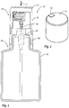
- FIG. 1 shows a first exemplary embodiment of a liquid dispenser with a discharge head in a sectional view.
- FIG. 2 shows the discharge head of the liquid dispenser in a perspective view, in which the upper face of the discharge head is visible.
- FIGS. 3 and 4 show the discharge head in sectional view in two different configurations.
- FIG. 5 shows a second exemplary embodiment of a liquid dispenser with a discharge head in a partially sectional view.
- FIGS. 6 and 7 show the discharge head in sectional view in two different configurations.
- FIGS. 8 and 9 show a second exemplary embodiment of a liquid dispenser with a discharge head in a partially sectional view in two different configurations.
- FIG. 1 shows in an overall view a first exemplary embodiment of a liquid dispenser 10 according to the invention.
- This liquid dispenser 10 has a base unit 20 comprising a liquid reservoir 22 and a housing part 23 positioned thereon, which together secure a pump device 80 , an outlet tube 81 being provided on the upper end thereof.
- a discharge head 30 which is covered by a protective cap 12 in the state of FIG. 1 , is positioned thereon. This discharge head 30 may be depressed in the direction of the arrow 2 for the purpose of discharging liquid.
- the discharge head 30 is provided to dispense liquid optionally in the form of a spray jet or in the form of a continuous liquid stream and/or droplets.
- the discharge head is provided in the manner shown in FIG. 2 with a switching surface 70 in the region of an actuating surface 14 .
- the relative arrangement of this switching surface 70 to the housing 32 of the discharge head 30 and the actuating surface 14 determines in which form the liquid is discharged.
- the discharge head 30 has a liquid inlet 38 which is fastened to the outlet tube 81 of the pump device 80 in the manner already described. From the liquid inlet 38 the liquid is conducted to a single liquid outlet 34 which the liquid to be discharged traverses when discharged. To this end, in the spray configuration of FIG. 3 the liquid flows along a liquid path 4 which leads through a radial inlet 53 into an internal part 50 of the discharge head 30 , which is arranged fixedly relative to the housing 32 of the discharge head. The internal part is penetrated by a spray duct 54 along which the liquid path 4 extends as far as a swirl chamber 58 .
- the liquid to be discharged is provided with a swirl so that it emerges through a spray opening 56 on the front face 52 of the internal part 50 in the form of a spray jet, without coming into contact again with other housing parts after being discharged.
- the path of the liquid in the spray configuration is illustrated by the liquid path 4 in FIG. 3 .
- the internal part 50 is arranged inside an outlet channel 36 which is displaceable in the horizontal direction relative to the housing 32 of the discharge head 30 in a translatory linear manner.
- FIG. 4 shows the droplet configuration of the discharge head 30 .
- an outlet sleeve 60 the inner face thereof forming the outlet channel 36 , is displaced such that a bypass duct 64 is opened.
- the flow path of the liquid is now the liquid path 6 which leads past the internal part 50 inside the outlet channel 36 as far as the liquid outlet 34 .
- the clear cross section of the bypass duct 64 is significantly larger than that of the spray opening 56 , the liquid flows at a slower speed to the liquid outlet 34 and thus may be discharged in a relatively depressurized manner.
- the bypass duct 64 is closed in the spray configuration of FIG. 3 .
- the spray duct 54 is open as before. Due to the increased flow resistance of the spray duct 54 and the spray opening 56 , however, the entire liquid or almost the entire liquid flows through the bypass duct 64 in the droplet configuration of FIG. 4 .
- the spray duct 54 is fully closed in the droplet configuration. This is structurally easy to achieve by a corresponding lengthening of the outlet sleeve 60 and the introduction of a radial through-passage, so that by means of this lengthening the lengthened outlet sleeve in the configuration of FIG. 4 closes the access to the inlet 53 of the internal part 50 .
- FIG. 5 shows an alternative design.
- a base unit 20 and a discharge head 30 which is displaceable in the direction of the arrow 2 are provided once again.
- the base unit 20 is provided with a liquid reservoir 22 which is provided as a pressure accumulator.
- a valve device 82 is used, said valve device being able to be opened by displacing an outlet pipe 83 in the direction of the arrow 2 .
- a base unit with a pump device corresponding to the exemplary embodiment set forth above may be used.
- a pressure accumulator with valve device may be used instead of the liquid reservoir with pump device.
- the discharge head is configured for producing a spray jet.
- the liquid flowing through the liquid inlet 38 enters the inlet 53 of the spray duct 54 since no other path leads to the liquid outlet 34 .
- the liquid is dispensed through the relatively narrow spray opening 56 at the end of the spray duct 54 .
- a swirl chamber could also be used here corresponding to the first exemplary embodiment, although a geometric design specifically adapted thereto is not shown in the figures. Also possible is a design with one or more fine nozzle openings for producing a spray jet.
- the internal part 50 is displaced to the right relative to the housing 32 , with reference to the drawings.
- the bypass duct 64 is opened so that now the liquid may flow in turn in a relatively depressurized manner to the liquid outlet 34 .
- the design relative to the first exemplary embodiment is reversed.
- the internal part 50 is displaceable in a linear manner relative to the housing 32 , whilst the outlet channel 36 remains fixed in position relative to the housing 32 .
- a switching surface 72 which may also be depressed in the direction of the arrow 2 is provided on the upper face of the discharge head 30 . This switching surface is coupled to a rear end of the internal part 50 via an oblique plane 72 a . Additionally, the internal part 50 is acted upon by force by means of a restoring spring 76 in the direction of the spray configuration of FIG. 6 .
- FIGS. 8 and 9 show a third exemplary embodiment in which the internal part 50 is displaceable relative to the housing 32 , coinciding with the design of FIGS. 5 to 7 , and in which a swirl chamber is provided for producing a spray jet, coinciding with the exemplary embodiment of FIGS. 1 to 4 .
- a switching surface is not provided.
- a housing part 23 which is connected fixedly in terms of rotation thereto, with a projection protruding into the discharge head, said projection acting as a guide element 25 and being at a variable spacing from the outlet pipe 83 in the manner of a spiral-shaped portion.
- a projection is provided on the internal part 50 which is linearly movable relative to the housing 32 , said projection having a deep groove which serves as guide slider 51 and into which the guide element 25 engages on the base part side.
- the action thereof is such that by a rotational movement of the discharge head 30 about a rotational axis 3 the position of the internal part 50 may be influenced, and thus the two described configurations, the spray configuration, on the one hand, and the droplet configuration, on the other hand, may be produced. Due to the depth of the groove in the guide slider 51 , it is nevertheless ensured that the projections do not hinder the depression of the discharge head.
Applications Claiming Priority (4)
| Application Number | Priority Date | Filing Date | Title |
|---|---|---|---|
| EP16180422.4 | 2016-07-20 | ||
| EP16180422 | 2016-07-20 | ||
| EP16180422.4A EP3272423B1 (de) | 2016-07-20 | 2016-07-20 | Austragkopf und spender mit einem austragkopf |
| PCT/EP2017/067300 WO2018015201A1 (de) | 2016-07-20 | 2017-07-10 | Flüssigkeitsspender mit einem austragkopf |
Publications (2)
| Publication Number | Publication Date |
|---|---|
| US20190160481A1 US20190160481A1 (en) | 2019-05-30 |
| US10946401B2 true US10946401B2 (en) | 2021-03-16 |
Family
ID=56507434
Family Applications (1)
| Application Number | Title | Priority Date | Filing Date |
|---|---|---|---|
| US16/314,078 Active 2037-08-28 US10946401B2 (en) | 2016-07-20 | 2017-07-10 | Liquid dispenser with a discharge head |
Country Status (5)
| Country | Link |
|---|---|
| US (1) | US10946401B2 (de) |
| EP (1) | EP3272423B1 (de) |
| KR (1) | KR20190030733A (de) |
| CN (1) | CN109475881B (de) |
| WO (1) | WO2018015201A1 (de) |
Families Citing this family (3)
| Publication number | Priority date | Publication date | Assignee | Title |
|---|---|---|---|---|
| ES2764084T3 (es) * | 2016-07-29 | 2020-06-02 | Aptar Radolfzell Gmbh | Dispensador de líquido con un cabezal de descarga |
| FR3106765B1 (fr) * | 2020-02-04 | 2022-12-30 | Eveon | Buse de pulvérisation de liquide sous forme de brouillard |
| CN111871156A (zh) * | 2020-07-22 | 2020-11-03 | 刘朋妃 | 一种化工含硫化氢气体冷却吸收系统的喷淋机构 |
Citations (13)
| Publication number | Priority date | Publication date | Assignee | Title |
|---|---|---|---|---|
| US3061203A (en) * | 1960-09-15 | 1962-10-30 | Kitabayashi Seiichi | Device for emitting painting material |
| US3648932A (en) * | 1969-10-27 | 1972-03-14 | Pittway Corp | Valve button with aspirator passageway |
| US3994442A (en) * | 1975-04-07 | 1976-11-30 | Seaquist Valve Company, Div. Of Pittway Corporation | Solid pattern mbu button |
| US4358057A (en) * | 1980-05-27 | 1982-11-09 | Ethyl Products Company | Fluid dispenser method and apparatus |
| EP0245822A2 (de) | 1986-05-15 | 1987-11-19 | S.C. Johnson & Son, Inc. | Kappe mit Doppelfunktion |
| US4911361A (en) | 1987-02-05 | 1990-03-27 | Atsushi Tada | Manually operated trigger type dispenser, method of assembling the same, and a spinner for use in the dispenser |
| US5261574A (en) | 1991-02-13 | 1993-11-16 | Societe Technique De Pulverisation S.T.E.P. | Closable and flow rate adjusting pushbutton for a hand-held fluid spray or dispenser device |
| EP0729792A2 (de) | 1995-02-28 | 1996-09-04 | Calmar Inc. | Sprühvorrichtung mit veränderlicher Sprühstrahlform |
| EP0638366B1 (de) | 1993-08-12 | 1997-04-09 | Alfred Kärcher GmbH & Co. | Strahlrohr für ein Hochdruckreinigungsgerät |
| US20050178858A1 (en) | 2004-02-13 | 2005-08-18 | Gianfranco Roman | Liquid spraying pistol with variable jet for gardening |
| WO2014138421A1 (en) | 2013-03-08 | 2014-09-12 | S.C. Johnson & Son, Inc. | Nozzle assembly and method for fluid dispensing |
| WO2015106776A1 (de) | 2014-01-17 | 2015-07-23 | Aptar Dortmund Gmbh | Abgabevorrichtung |
| US20160023221A1 (en) | 2014-07-24 | 2016-01-28 | John Metz | Dual flow cap assembly for container |
-
2016
- 2016-07-20 EP EP16180422.4A patent/EP3272423B1/de active Active
-
2017
- 2017-07-10 US US16/314,078 patent/US10946401B2/en active Active
- 2017-07-10 WO PCT/EP2017/067300 patent/WO2018015201A1/de active Application Filing
- 2017-07-10 CN CN201780044945.5A patent/CN109475881B/zh active Active
- 2017-07-10 KR KR1020197004879A patent/KR20190030733A/ko not_active Application Discontinuation
Patent Citations (17)
| Publication number | Priority date | Publication date | Assignee | Title |
|---|---|---|---|---|
| US3061203A (en) * | 1960-09-15 | 1962-10-30 | Kitabayashi Seiichi | Device for emitting painting material |
| US3648932A (en) * | 1969-10-27 | 1972-03-14 | Pittway Corp | Valve button with aspirator passageway |
| US3994442A (en) * | 1975-04-07 | 1976-11-30 | Seaquist Valve Company, Div. Of Pittway Corporation | Solid pattern mbu button |
| US4358057A (en) * | 1980-05-27 | 1982-11-09 | Ethyl Products Company | Fluid dispenser method and apparatus |
| EP0245822A2 (de) | 1986-05-15 | 1987-11-19 | S.C. Johnson & Son, Inc. | Kappe mit Doppelfunktion |
| US4911361A (en) | 1987-02-05 | 1990-03-27 | Atsushi Tada | Manually operated trigger type dispenser, method of assembling the same, and a spinner for use in the dispenser |
| US5261574A (en) | 1991-02-13 | 1993-11-16 | Societe Technique De Pulverisation S.T.E.P. | Closable and flow rate adjusting pushbutton for a hand-held fluid spray or dispenser device |
| EP0638366B1 (de) | 1993-08-12 | 1997-04-09 | Alfred Kärcher GmbH & Co. | Strahlrohr für ein Hochdruckreinigungsgerät |
| US5590837A (en) * | 1995-02-28 | 1997-01-07 | Calmar Inc. | Sprayer having variable spray pattern |
| EP0729792A2 (de) | 1995-02-28 | 1996-09-04 | Calmar Inc. | Sprühvorrichtung mit veränderlicher Sprühstrahlform |
| US20050178858A1 (en) | 2004-02-13 | 2005-08-18 | Gianfranco Roman | Liquid spraying pistol with variable jet for gardening |
| CN1656878A (zh) | 2004-02-13 | 2005-08-24 | 客来博股份公司 | 一种园林用带可变喷嘴液体喷枪 |
| WO2014138421A1 (en) | 2013-03-08 | 2014-09-12 | S.C. Johnson & Son, Inc. | Nozzle assembly and method for fluid dispensing |
| WO2015106776A1 (de) | 2014-01-17 | 2015-07-23 | Aptar Dortmund Gmbh | Abgabevorrichtung |
| US9957100B2 (en) | 2014-01-17 | 2018-05-01 | Aptar Dortmund Gmbh | Dispensing device |
| US20160023221A1 (en) | 2014-07-24 | 2016-01-28 | John Metz | Dual flow cap assembly for container |
| US9527635B2 (en) | 2014-07-24 | 2016-12-27 | John Metz | Dual flow cap assembly for container |
Non-Patent Citations (3)
| Title |
|---|
| Chinese Office Action with English Translation issued in corresponding Chinese Application No. 201780044945.5 dated Jun. 3, 2020 (12 pages). |
| International Search Report with English translation issued in International Application No. PCT/EP2017/067300 dated Sep. 15, 2017 (7 pages). |
| Written Opinion of International Searching Authority issued in International Application No. PCT/EP2017/067300 dated Sep. 15, 2017 (5 pages). |
Also Published As
| Publication number | Publication date |
|---|---|
| CN109475881B (zh) | 2021-08-24 |
| WO2018015201A1 (de) | 2018-01-25 |
| EP3272423A1 (de) | 2018-01-24 |
| CN109475881A (zh) | 2019-03-15 |
| KR20190030733A (ko) | 2019-03-22 |
| EP3272423B1 (de) | 2018-12-19 |
| US20190160481A1 (en) | 2019-05-30 |
Similar Documents
| Publication | Publication Date | Title |
|---|---|---|
| US20200230625A1 (en) | Multi-function sprayhead | |
| US10946401B2 (en) | Liquid dispenser with a discharge head | |
| EP1446230B1 (de) | Teleskopschaumdüse | |
| KR100294813B1 (ko) | 샤워헤드 | |
| CN1059610C (zh) | 具有可变喷雾方式的喷雾器 | |
| US20060273192A1 (en) | Rotary irrigation sprinkler nozzle | |
| SK93694A3 (en) | Spray pump with many apertures for dispensing liquid in different spray patterns | |
| CN110121390B (zh) | 直观的宽度控制喷洒器 | |
| US8840044B2 (en) | Spray head and device for the dispensing of a liquid | |
| EP0729792B1 (de) | Sprühvorrichtung mit veränderlicher Sprühstrahlform | |
| JP2015513463A (ja) | 分注ヘッド装置及び方法 | |
| JPH07256154A (ja) | 噴霧装置 | |
| US9126212B2 (en) | Adjustable dialed spray nozzle | |
| JP5921861B2 (ja) | 液体噴出器 | |
| US9493292B2 (en) | Variable spray head | |
| US20090256008A1 (en) | Trigger Sprayer Nozzle Assembly with Pull/Push Foaming Tube | |
| CN109475891B (zh) | 带有发送头的液体配送器 | |
| EP3265234A1 (de) | Sprühvorrichtung | |
| JPH0336779Y2 (de) | ||
| JP5435571B2 (ja) | トリガー式噴霧器 | |
| JP5489158B2 (ja) | トリガー式噴霧器 | |
| CN219923328U (zh) | 一种水路切换机构及出水装置 | |
| JP2017213517A (ja) | 液体噴出器 | |
| JPH091007A (ja) | トリガー作動式ポンプスプレー機 | |
| JPH062761Y2 (ja) | 粘性液体の噴霧装置 |
Legal Events
| Date | Code | Title | Description |
|---|---|---|---|
| FEPP | Fee payment procedure |
Free format text: ENTITY STATUS SET TO UNDISCOUNTED (ORIGINAL EVENT CODE: BIG.); ENTITY STATUS OF PATENT OWNER: LARGE ENTITY |
|
| AS | Assignment |
Owner name: APTAR RADOLFZELL GMBH, GERMANY Free format text: ASSIGNMENT OF ASSIGNORS INTEREST;ASSIGNOR:BAUMANN, TOBIAS;REEL/FRAME:047881/0019 Effective date: 20181211 |
|
| STPP | Information on status: patent application and granting procedure in general |
Free format text: DOCKETED NEW CASE - READY FOR EXAMINATION |
|
| STPP | Information on status: patent application and granting procedure in general |
Free format text: NON FINAL ACTION MAILED |
|
| STPP | Information on status: patent application and granting procedure in general |
Free format text: RESPONSE TO NON-FINAL OFFICE ACTION ENTERED AND FORWARDED TO EXAMINER |
|
| STPP | Information on status: patent application and granting procedure in general |
Free format text: RESPONSE AFTER FINAL ACTION FORWARDED TO EXAMINER |
|
| STCF | Information on status: patent grant |
Free format text: PATENTED CASE |