EP0729792A2 - Sprühvorrichtung mit veränderlicher Sprühstrahlform - Google Patents
Sprühvorrichtung mit veränderlicher Sprühstrahlform Download PDFInfo
- Publication number
- EP0729792A2 EP0729792A2 EP95119658A EP95119658A EP0729792A2 EP 0729792 A2 EP0729792 A2 EP 0729792A2 EP 95119658 A EP95119658 A EP 95119658A EP 95119658 A EP95119658 A EP 95119658A EP 0729792 A2 EP0729792 A2 EP 0729792A2
- Authority
- EP
- European Patent Office
- Prior art keywords
- probe
- cap
- sprayer
- skirt
- fluid
- Prior art date
- Legal status (The legal status is an assumption and is not a legal conclusion. Google has not performed a legal analysis and makes no representation as to the accuracy of the status listed.)
- Granted
Links
- 239000007921 spray Substances 0.000 title claims abstract description 33
- 239000000523 sample Substances 0.000 claims abstract description 54
- 239000012530 fluid Substances 0.000 claims abstract description 41
- 238000006073 displacement reaction Methods 0.000 claims description 5
- 238000011144 upstream manufacturing Methods 0.000 claims description 4
- 230000000903 blocking effect Effects 0.000 claims description 3
- 239000003595 mist Substances 0.000 claims 1
- 230000000694 effects Effects 0.000 abstract description 3
- 238000005086 pumping Methods 0.000 description 6
- 239000000047 product Substances 0.000 description 4
- 239000011324 bead Substances 0.000 description 2
- 230000008901 benefit Effects 0.000 description 2
- 101000793686 Homo sapiens Azurocidin Proteins 0.000 description 1
- 244000273618 Sphenoclea zeylanica Species 0.000 description 1
- 230000001276 controlling effect Effects 0.000 description 1
- 239000012263 liquid product Substances 0.000 description 1
- 230000004048 modification Effects 0.000 description 1
- 238000012986 modification Methods 0.000 description 1
- 238000000465 moulding Methods 0.000 description 1
- 230000037361 pathway Effects 0.000 description 1
- 230000001105 regulatory effect Effects 0.000 description 1
Images
Classifications
-
- B—PERFORMING OPERATIONS; TRANSPORTING
- B05—SPRAYING OR ATOMISING IN GENERAL; APPLYING FLUENT MATERIALS TO SURFACES, IN GENERAL
- B05B—SPRAYING APPARATUS; ATOMISING APPARATUS; NOZZLES
- B05B11/00—Single-unit hand-held apparatus in which flow of contents is produced by the muscular force of the operator at the moment of use
- B05B11/01—Single-unit hand-held apparatus in which flow of contents is produced by the muscular force of the operator at the moment of use characterised by the means producing the flow
- B05B11/02—Membranes or pistons acting on the contents inside the container, e.g. follower pistons
-
- B—PERFORMING OPERATIONS; TRANSPORTING
- B05—SPRAYING OR ATOMISING IN GENERAL; APPLYING FLUENT MATERIALS TO SURFACES, IN GENERAL
- B05B—SPRAYING APPARATUS; ATOMISING APPARATUS; NOZZLES
- B05B1/00—Nozzles, spray heads or other outlets, with or without auxiliary devices such as valves, heating means
- B05B1/34—Nozzles, spray heads or other outlets, with or without auxiliary devices such as valves, heating means designed to influence the nature of flow of the liquid or other fluent material, e.g. to produce swirl
- B05B1/3405—Nozzles, spray heads or other outlets, with or without auxiliary devices such as valves, heating means designed to influence the nature of flow of the liquid or other fluent material, e.g. to produce swirl to produce swirl
- B05B1/341—Nozzles, spray heads or other outlets, with or without auxiliary devices such as valves, heating means designed to influence the nature of flow of the liquid or other fluent material, e.g. to produce swirl to produce swirl before discharging the liquid or other fluent material, e.g. in a swirl chamber upstream the spray outlet
- B05B1/3478—Nozzles, spray heads or other outlets, with or without auxiliary devices such as valves, heating means designed to influence the nature of flow of the liquid or other fluent material, e.g. to produce swirl to produce swirl before discharging the liquid or other fluent material, e.g. in a swirl chamber upstream the spray outlet the liquid flowing at least two different courses before reaching the swirl chamber
-
- B—PERFORMING OPERATIONS; TRANSPORTING
- B05—SPRAYING OR ATOMISING IN GENERAL; APPLYING FLUENT MATERIALS TO SURFACES, IN GENERAL
- B05B—SPRAYING APPARATUS; ATOMISING APPARATUS; NOZZLES
- B05B1/00—Nozzles, spray heads or other outlets, with or without auxiliary devices such as valves, heating means
- B05B1/34—Nozzles, spray heads or other outlets, with or without auxiliary devices such as valves, heating means designed to influence the nature of flow of the liquid or other fluent material, e.g. to produce swirl
- B05B1/3405—Nozzles, spray heads or other outlets, with or without auxiliary devices such as valves, heating means designed to influence the nature of flow of the liquid or other fluent material, e.g. to produce swirl to produce swirl
- B05B1/341—Nozzles, spray heads or other outlets, with or without auxiliary devices such as valves, heating means designed to influence the nature of flow of the liquid or other fluent material, e.g. to produce swirl to produce swirl before discharging the liquid or other fluent material, e.g. in a swirl chamber upstream the spray outlet
- B05B1/3421—Nozzles, spray heads or other outlets, with or without auxiliary devices such as valves, heating means designed to influence the nature of flow of the liquid or other fluent material, e.g. to produce swirl to produce swirl before discharging the liquid or other fluent material, e.g. in a swirl chamber upstream the spray outlet with channels emerging substantially tangentially in the swirl chamber
- B05B1/3431—Nozzles, spray heads or other outlets, with or without auxiliary devices such as valves, heating means designed to influence the nature of flow of the liquid or other fluent material, e.g. to produce swirl to produce swirl before discharging the liquid or other fluent material, e.g. in a swirl chamber upstream the spray outlet with channels emerging substantially tangentially in the swirl chamber the channels being formed at the interface of cooperating elements, e.g. by means of grooves
- B05B1/3436—Nozzles, spray heads or other outlets, with or without auxiliary devices such as valves, heating means designed to influence the nature of flow of the liquid or other fluent material, e.g. to produce swirl to produce swirl before discharging the liquid or other fluent material, e.g. in a swirl chamber upstream the spray outlet with channels emerging substantially tangentially in the swirl chamber the channels being formed at the interface of cooperating elements, e.g. by means of grooves the interface being a plane perpendicular to the outlet axis
-
- B—PERFORMING OPERATIONS; TRANSPORTING
- B05—SPRAYING OR ATOMISING IN GENERAL; APPLYING FLUENT MATERIALS TO SURFACES, IN GENERAL
- B05B—SPRAYING APPARATUS; ATOMISING APPARATUS; NOZZLES
- B05B11/00—Single-unit hand-held apparatus in which flow of contents is produced by the muscular force of the operator at the moment of use
- B05B11/0005—Components or details
-
- B—PERFORMING OPERATIONS; TRANSPORTING
- B05—SPRAYING OR ATOMISING IN GENERAL; APPLYING FLUENT MATERIALS TO SURFACES, IN GENERAL
- B05B—SPRAYING APPARATUS; ATOMISING APPARATUS; NOZZLES
- B05B1/00—Nozzles, spray heads or other outlets, with or without auxiliary devices such as valves, heating means
- B05B1/12—Nozzles, spray heads or other outlets, with or without auxiliary devices such as valves, heating means capable of producing different kinds of discharge, e.g. either jet or spray
-
- B—PERFORMING OPERATIONS; TRANSPORTING
- B05—SPRAYING OR ATOMISING IN GENERAL; APPLYING FLUENT MATERIALS TO SURFACES, IN GENERAL
- B05B—SPRAYING APPARATUS; ATOMISING APPARATUS; NOZZLES
- B05B1/00—Nozzles, spray heads or other outlets, with or without auxiliary devices such as valves, heating means
- B05B1/14—Nozzles, spray heads or other outlets, with or without auxiliary devices such as valves, heating means with multiple outlet openings; with strainers in or outside the outlet opening
- B05B1/16—Nozzles, spray heads or other outlets, with or without auxiliary devices such as valves, heating means with multiple outlet openings; with strainers in or outside the outlet opening having selectively- effective outlets
- B05B1/1627—Nozzles, spray heads or other outlets, with or without auxiliary devices such as valves, heating means with multiple outlet openings; with strainers in or outside the outlet opening having selectively- effective outlets with a selecting mechanism comprising a gate valve, a sliding valve or a cock
- B05B1/1636—Nozzles, spray heads or other outlets, with or without auxiliary devices such as valves, heating means with multiple outlet openings; with strainers in or outside the outlet opening having selectively- effective outlets with a selecting mechanism comprising a gate valve, a sliding valve or a cock by relative rotative movement of the valve elements
-
- B—PERFORMING OPERATIONS; TRANSPORTING
- B05—SPRAYING OR ATOMISING IN GENERAL; APPLYING FLUENT MATERIALS TO SURFACES, IN GENERAL
- B05B—SPRAYING APPARATUS; ATOMISING APPARATUS; NOZZLES
- B05B11/00—Single-unit hand-held apparatus in which flow of contents is produced by the muscular force of the operator at the moment of use
- B05B11/01—Single-unit hand-held apparatus in which flow of contents is produced by the muscular force of the operator at the moment of use characterised by the means producing the flow
- B05B11/10—Pump arrangements for transferring the contents from the container to a pump chamber by a sucking effect and forcing the contents out through the dispensing nozzle
- B05B11/1042—Components or details
- B05B11/1052—Actuation means
- B05B11/1056—Actuation means comprising rotatable or articulated levers
- B05B11/1057—Triggers, i.e. actuation means consisting of a single lever having one end rotating or pivoting around an axis or a hinge fixedly attached to the container, and another end directly actuated by the user
Definitions
- This invention relates generally to a pump sprayer of either the finger actuated or trigger actuated types, including a nozzle cap surrounding a spinner probe, the cap having spin mechanics of some known type for imparting a spin or swirl at a given velocity for issuance through the discharge orifice in a given spray pattern having a predetermined, divergent spray cone.
- the invention provides for varying the spray pattern by negating the spin velocity as product is directed from the discharge passage through an additional fluid path to the spin mechanics, this path being established by a through opening located in the probe.
- the second fluid path may be selectively opened and closed to regulate the size of the spray cone.
- Known fingertip sprayers typically have a nozzle cap mounted within a reciprocable plunger head, the cap having spin mechanics and surrounding a spinner probe on the head. A fluid path from the discharge passage is established between the probe and a surrounding cap skirt to produce a dedicated spray pattern upon plunger reciprocation.
- Known pump sprayers of the trigger actuated type include a nozzle cap rotatable between spray-off and stream-off positions, without axial shifting, requiring radial and tangential channels at the end of the spinner probe for this purpose.
- U.S. Patent 5,368,234 discloses a nozzle assembly for a trigger sprayer which provides for regulation of the spray pattern by controlling the size of openings from a single fluid flow path into the swirl chamber upon cap rotation. A stream discharge is effected upon a shifting of the nozzle cap along its axis.
- a nozzle cap which itself contains the spin mechanics simplifies the molding operation from which the pump sprayers are constructed, and avoids the need for a complex spinner probe structure.
- the fingertip sprayer and/or for the trigger operated sprayer to provide a narrower spray cone using the existing spin mechanics structure molded into the nozzle cap, the less divergent spray cone satisfying the need for reducing the area of spray against a target of a given size to be wetted during pumping operation.
- the spinner probe is provided with a through opening communicating at its downstream end with the spin mechanics, and at its upstream end with the discharge passage to establish the second fluid flow path for negating some of the tangential velocity at the spin mechanics to thereby reduce the size of the divergent spray pattern.
- the nozzle cap surrounds the probe and is mounted for rotation about its axis without axial displacement for selectively regulating the spray pattern as the nozzle cap is structured to block and uncover the through opening upon cap rotation.
- the through opening in the probe has a terminal end at an outer surface of the probe within the cap skirt, a first section of an inner wall of the cap skirt blocking the terminal end in a first relative rotative position of the cap, and a second section of the inner wall of the cap skirt being spaced from the terminal end for unblocking the through opening in a second relative rotative position of the cap.
- the inner wall of the skirt may be eccentric relative to the central axis of the probe, such that the first wall section in the first relative rotative position is tangent to the probe for covering the terminal end, and the through opening in the probe may extend at an angle relative to the central axis of the probe.
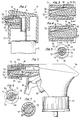
- a fingertip actuated pump sprayer is generally designated 10 in Fig. 1 as essentially comprising a pump body including a hollow piston stem 11 which extends through a central opening in a crown portion 12 of a container closure (not otherwise shown) for mounting the sprayer on a container (not shown) of liquid product to be dispensed upon pumping.
- the hollow stem of the pump piston extends for reciprocation within a pump cylinder (not shown) in the normal manner.
- the pump body further includes a plunger head 13 mounted on the stem to effect reciprocation upon application of a downward finger force applied to the top of the plunger head against the spring bias of the piston return spring (not shown).
- the hollow piston stem defines a fluid discharge passage 14 which communicates at its upper end with a lateral pathway 15 in the head, and the head includes a transversely extending spinner probe 16 surrounded by a nozzle cap 17 having a coaxial discharge orifice 18.
- the nozzle cap is sealingly mounted within an annular bore 19 of the plunger head for rotation about its central axis without axial displacement as by the provision of a cooperating bead 21 and groove 22 arrangement.
- the nozzle cap extends outwardly of the front circular face 23 of the plunger head to permit grasping by the operator for cap rotation.
- the inner front face of the nozzle cap is provided with some type of known spin mechanics, including a plurality of tangential channels 24 terminating at the downstream end thereof in a central spin or swirl chamber 25 coaxial with the discharge orifice.
- probe 16 is generally cylindrical and may have a conically tapered forward end as at 26.
- Cylindrical cap skirt 27 has a generally cylindrical inner wall 28 (Fig. 7) surrounding tapered end 26 of the probe, wall 28 containing one or more longitudinal grooves 29 connecting with tangential channels 24 (Fig. 5).
- Inner wall section 31 of the cap skirt which surrounds the cylindrical portion of the spinner probe is eccentrically shaped relative to the central axis of the cap, as shown in Figs. 5, 6.
- a portion of wall section 31 is tangent to the probe cylindrical section, and the remaining portion of the wall section 31 is spaced from the cylindrical portion of the probe.
- Grooves 29 in the cylindrical portion of the cap skirt are offset relative to the tangency between wall portion 31 and the probe, as shown in Figs. 5, 6, such that grooves 29 terminate in that portion of wall 31 which is spaced from the outer surface of the probe.
- grooves 29 establish a first fluid path between discharge passage 14 and the spin mechanics which imparts a spin at a given velocity to the fluid to be discharged through the discharge orifice in a spray pattern of a divergent spray cone or plume of a given conical size.
- the probe is provided with a through opening to establish a second fluid flow path from the discharge passage to the spin mechanics such that, during pumping, fluid flows along both the first and second fluid paths, and some of the spin velocity is negated by the latter to effect a discharge of fluid through orifice 18 as a divergent spray having a cone size more narrow than the size of the spay cone produced by the pumping of fluid only through the first fluid path via grooves 29.
- the through opening 32 opens at its downstream end essentially into the spin chamber and has an upstream terminal end 33 located at outer surface 34 at the cylindrical portion of the probe. As shown in Figs. 3, 4, the through opening may lie at an angle to the central axis of the probe.
- Figs. 3 and 5 illustrate the relative rotative position of the nozzle cap wherein that section of its inner wall 31 is tangential to outer surface 34 of the probe at which terminal end 33 is located for covering the terminal end of the through opening to thereby block the second fluid flow path whereupon fluid reaches the spin mechanics during pumping only through the first fluid path to thereby issue through the discharge orifice as a wide divergent spray cone.
- inner wall 31 of the cap skirt presents a gap 35 in the vicinity of terminal end 33 whereupon the through opening is unblocked, permitting fluid to flow along both the first and the second flow paths for producing a less divergent spray cone as some of the tangential velocity at the spin mechanics is negated.
- Fig. 2 illustrates a trigger actuated pump sprayer 36 which likewise incorporates the invention, the trigger sprayer being mounted on a container (not shown) of product to be dispensed by the provision of a closure cap 37.
- a trigger actuator 38 is hingedly mounted to the pump body as in a normal manner and engages a pump piston 39 for pumping product through discharge passage 41.
- the pump body has an outwardly extending nozzle 42 into which probe 16 extends.
- Nozzle cap 43 surrounds the nozzle and is mounted thereon for relative rotation about its central axis, without axial displacement, by the provision of a cooperating bead and groove 44, 45.
- the end wall of the nozzle cap is the same as that of the nozzle cap 17 in that it includes discharge orifice 18 as well as tangential channels 24 opening into swirl chamber 25.
- Nozzle cap 43 has an inner skirt 46 containing grooves 29 and having its inner wall structured relative to the probe the same as described with reference to Fig. 1.
- cap rotation between the Fig. 3 and Fig. 4 positions regulates the spray pattern from a wide divergent spray to a less divergent spray in the same manner as described with reference to Figs. 3 to 7.
Landscapes
- Containers And Packaging Bodies Having A Special Means To Remove Contents (AREA)
- Nozzles (AREA)
- Closures For Containers (AREA)
- Special Spraying Apparatus (AREA)
- Catching Or Destruction (AREA)
Applications Claiming Priority (2)
| Application Number | Priority Date | Filing Date | Title |
|---|---|---|---|
| US08/395,851 US5590837A (en) | 1995-02-28 | 1995-02-28 | Sprayer having variable spray pattern |
| US395851 | 1995-02-28 |
Publications (3)
| Publication Number | Publication Date |
|---|---|
| EP0729792A2 true EP0729792A2 (de) | 1996-09-04 |
| EP0729792A3 EP0729792A3 (de) | 1997-04-02 |
| EP0729792B1 EP0729792B1 (de) | 1999-03-31 |
Family
ID=23564800
Family Applications (1)
| Application Number | Title | Priority Date | Filing Date |
|---|---|---|---|
| EP95119658A Expired - Lifetime EP0729792B1 (de) | 1995-02-28 | 1995-12-13 | Sprühvorrichtung mit veränderlicher Sprühstrahlform |
Country Status (10)
| Country | Link |
|---|---|
| US (1) | US5590837A (de) |
| EP (1) | EP0729792B1 (de) |
| JP (1) | JP3226782B2 (de) |
| KR (1) | KR100385696B1 (de) |
| AU (1) | AU694594B2 (de) |
| BR (1) | BR9600065A (de) |
| CA (1) | CA2164907C (de) |
| DE (1) | DE69508734T2 (de) |
| ES (1) | ES2131261T3 (de) |
| TW (1) | TW281642B (de) |
Cited By (3)
| Publication number | Priority date | Publication date | Assignee | Title |
|---|---|---|---|---|
| WO1998043743A3 (de) * | 1997-04-01 | 1998-12-30 | Siemens Ag | Düse, verwendung einer düse und verfahren zur eindüsung eines ersten fluids in ein zweites fluid |
| EP3272423A1 (de) * | 2016-07-20 | 2018-01-24 | Aptar Radolfzell GmbH | Austragkopf und spender mit einem austragkopf |
| WO2018224206A1 (de) * | 2017-06-08 | 2018-12-13 | Aptar Radolfzell Gmbh | Austragkopf für die nasale applikation von flüssigkeit aus einem druckspeicher |
Families Citing this family (25)
| Publication number | Priority date | Publication date | Assignee | Title |
|---|---|---|---|---|
| US5590837A (en) * | 1995-02-28 | 1997-01-07 | Calmar Inc. | Sprayer having variable spray pattern |
| US7588198B2 (en) * | 2003-12-18 | 2009-09-15 | S.C. Johnson & Son, Inc. | Power sprayer |
| US7097119B2 (en) * | 2003-12-18 | 2006-08-29 | Cepia, Llc | Power sprayer |
| US7246755B2 (en) * | 2003-12-18 | 2007-07-24 | Cepia, Llc | Power sprayer |
| US8602386B2 (en) * | 2007-12-21 | 2013-12-10 | S.C. Johnson & Son, Inc. | Valve with actuator assist |
| US7648083B2 (en) * | 2003-12-18 | 2010-01-19 | S.C. Johnson & Son, Inc. | Power sprayer |
| US7384006B2 (en) * | 2003-12-18 | 2008-06-10 | Cepia, Llc | Power sprayer |
| US7328859B2 (en) | 2003-12-18 | 2008-02-12 | Cepia, Llc | Power sprayer |
| USD519371S1 (en) | 2004-04-27 | 2006-04-25 | Cepia, Llc | Sprayer |
| US7354008B2 (en) * | 2004-09-24 | 2008-04-08 | Bowles Fluidics Corporation | Fluidic nozzle for trigger spray applications |
| DE102005024612A1 (de) * | 2005-05-25 | 2006-11-30 | Wella Ag | Sprühkopf mit einem Düseneinsatzteil |
| US8844841B2 (en) * | 2009-03-19 | 2014-09-30 | S.C. Johnson & Son, Inc. | Nozzle assembly for liquid dispenser |
| USD681470S1 (en) | 2010-01-08 | 2013-05-07 | Oms Investments, Inc. | Dispensing container |
| USD628898S1 (en) | 2010-02-19 | 2010-12-14 | Medtech Products, Inc. | Spray nozzle |
| USD628901S1 (en) | 2010-02-19 | 2010-12-14 | Medtech Products, Inc. | Spray nozzle |
| USD628899S1 (en) | 2010-02-19 | 2010-12-14 | Medtech Products, Inc. | Spray nozzle |
| USD628900S1 (en) | 2010-02-19 | 2010-12-14 | Medtech Products, Inc. | Spray nozzle |
| US20120223161A1 (en) | 2011-03-01 | 2012-09-06 | Smg Brands, Inc. | Ready-to-use hose end sprayer |
| USD670982S1 (en) | 2011-03-01 | 2012-11-20 | Smg Brands, Inc. | Applicator |
| US20120223160A1 (en) | 2011-03-01 | 2012-09-06 | Smg Brands, Inc. | Applicator with collapsible wand |
| USD650046S1 (en) | 2011-03-01 | 2011-12-06 | Smg Brands, Inc. | Sprayer |
| USD708301S1 (en) | 2013-03-15 | 2014-07-01 | Oms Investments, Inc. | Liquid sprayer |
| CN104441657B (zh) * | 2014-11-12 | 2016-08-17 | 广东工业大学 | 一种可控口径的3d打印机喷头及其控制方法 |
| KR101848688B1 (ko) * | 2016-04-06 | 2018-05-24 | 주식회사 센트온 | 향 분사기의 분사노즐 결합용 분사캡 및 그 사용방법 |
| JP2023131731A (ja) * | 2022-03-09 | 2023-09-22 | 株式会社トップ | 噴射口部材 |
Citations (2)
| Publication number | Priority date | Publication date | Assignee | Title |
|---|---|---|---|---|
| US4706888A (en) | 1986-07-11 | 1987-11-17 | Calmar, Inc. | Multi-purpose nozzle assembly |
| US5368234A (en) | 1991-12-13 | 1994-11-29 | Contico International, Inc. | Nozzle assembly for trigger sprayer |
Family Cites Families (17)
| Publication number | Priority date | Publication date | Assignee | Title |
|---|---|---|---|---|
| US555573A (en) * | 1896-03-03 | Philip | ||
| US1903354A (en) * | 1929-11-14 | 1933-04-04 | Oscar E Backus | Nozzle |
| US3967765A (en) * | 1972-08-09 | 1976-07-06 | Leeds And Micallef | Multiple purpose nozzle |
| US3843030A (en) * | 1972-08-09 | 1974-10-22 | Leeds & Micallef | Multiple purpose nozzle |
| US3994442A (en) * | 1975-04-07 | 1976-11-30 | Seaquist Valve Company, Div. Of Pittway Corporation | Solid pattern mbu button |
| US4020982A (en) * | 1975-10-10 | 1977-05-03 | Leeds And Micallef | Rotary shut-off nozzle |
| IN148848B (de) * | 1977-03-02 | 1981-06-27 | Abplanalp Robert H | |
| US4109869A (en) * | 1977-06-16 | 1978-08-29 | Dutton-Lainson Company | Oiler with adjustable spray nozzle |
| DE2733102A1 (de) * | 1977-07-22 | 1979-02-01 | Bayer Ag | Verfahren und vorrichtung zum zerstaeuben von fluessigkeiten |
| US4234128A (en) * | 1978-02-06 | 1980-11-18 | The Afa Corporation | Nozzle assembly |
| US4189064A (en) * | 1978-06-01 | 1980-02-19 | Diamond International Corporation | Pumps sprayer |
| US4247048A (en) * | 1979-03-29 | 1981-01-27 | Ethyl Corporation | Dispensing nozzle |
| US4358057A (en) * | 1980-05-27 | 1982-11-09 | Ethyl Products Company | Fluid dispenser method and apparatus |
| US4365751A (en) * | 1980-09-26 | 1982-12-28 | Yoshino Kogyosho Co., Ltd. | Trigger type liquid injector |
| US4516695A (en) * | 1981-02-09 | 1985-05-14 | The Afa Corporation | Child-resistant liquid dispenser sprayer or like apparatus |
| US4890792A (en) * | 1988-02-19 | 1990-01-02 | Afa Products Inc. | Nozzle assembly |
| US5590837A (en) * | 1995-02-28 | 1997-01-07 | Calmar Inc. | Sprayer having variable spray pattern |
-
1995
- 1995-02-28 US US08/395,851 patent/US5590837A/en not_active Expired - Lifetime
- 1995-11-21 TW TW084112355A patent/TW281642B/zh active
- 1995-12-11 CA CA002164907A patent/CA2164907C/en not_active Expired - Fee Related
- 1995-12-13 EP EP95119658A patent/EP0729792B1/de not_active Expired - Lifetime
- 1995-12-13 ES ES95119658T patent/ES2131261T3/es not_active Expired - Lifetime
- 1995-12-13 DE DE69508734T patent/DE69508734T2/de not_active Expired - Lifetime
- 1995-12-26 KR KR1019950056474A patent/KR100385696B1/ko not_active Expired - Fee Related
-
1996
- 1996-01-11 BR BR9600065A patent/BR9600065A/pt not_active IP Right Cessation
- 1996-01-24 AU AU42143/96A patent/AU694594B2/en not_active Ceased
- 1996-02-09 JP JP04812496A patent/JP3226782B2/ja not_active Expired - Fee Related
Patent Citations (2)
| Publication number | Priority date | Publication date | Assignee | Title |
|---|---|---|---|---|
| US4706888A (en) | 1986-07-11 | 1987-11-17 | Calmar, Inc. | Multi-purpose nozzle assembly |
| US5368234A (en) | 1991-12-13 | 1994-11-29 | Contico International, Inc. | Nozzle assembly for trigger sprayer |
Cited By (9)
| Publication number | Priority date | Publication date | Assignee | Title |
|---|---|---|---|---|
| WO1998043743A3 (de) * | 1997-04-01 | 1998-12-30 | Siemens Ag | Düse, verwendung einer düse und verfahren zur eindüsung eines ersten fluids in ein zweites fluid |
| EP3272423A1 (de) * | 2016-07-20 | 2018-01-24 | Aptar Radolfzell GmbH | Austragkopf und spender mit einem austragkopf |
| WO2018015201A1 (de) * | 2016-07-20 | 2018-01-25 | Aptar Radolfzell Gmbh | Flüssigkeitsspender mit einem austragkopf |
| US10946401B2 (en) | 2016-07-20 | 2021-03-16 | Aptar Radolfzell Gmbh | Liquid dispenser with a discharge head |
| WO2018224206A1 (de) * | 2017-06-08 | 2018-12-13 | Aptar Radolfzell Gmbh | Austragkopf für die nasale applikation von flüssigkeit aus einem druckspeicher |
| EP3552644A1 (de) * | 2017-06-08 | 2019-10-16 | Aptar Radolfzell GmbH | Austragkopf für die nasale applikation von flüssigkeit aus einem druckspeicher |
| CN110740772A (zh) * | 2017-06-08 | 2020-01-31 | 阿普塔尔拉多尔夫策尔有限责任公司 | 用于对鼻子施用来自压力存储器的液体的排出头 |
| CN110740772B (zh) * | 2017-06-08 | 2022-03-29 | 阿普塔尔拉多尔夫策尔有限责任公司 | 用于对鼻子施用来自压力存储器的液体的排出头 |
| US11833295B2 (en) | 2017-06-08 | 2023-12-05 | Aptar Radolfzell Gmbh | Discharge head for the nasal application of liquid from a pressure reservoir |
Also Published As
| Publication number | Publication date |
|---|---|
| TW281642B (en) | 1996-07-21 |
| JPH08243449A (ja) | 1996-09-24 |
| DE69508734D1 (de) | 1999-05-06 |
| EP0729792A3 (de) | 1997-04-02 |
| ES2131261T3 (es) | 1999-07-16 |
| HK1011314A1 (en) | 1999-07-09 |
| AU694594B2 (en) | 1998-07-23 |
| KR960031001A (ko) | 1996-09-17 |
| DE69508734T2 (de) | 1999-11-11 |
| BR9600065A (pt) | 1998-01-27 |
| CA2164907C (en) | 2001-02-13 |
| EP0729792B1 (de) | 1999-03-31 |
| US5590837A (en) | 1997-01-07 |
| JP3226782B2 (ja) | 2001-11-05 |
| AU4214396A (en) | 1996-09-05 |
| CA2164907A1 (en) | 1996-08-29 |
| KR100385696B1 (ko) | 2003-08-21 |
Similar Documents
| Publication | Publication Date | Title |
|---|---|---|
| US5590837A (en) | Sprayer having variable spray pattern | |
| US5593094A (en) | Pump sprayer having variable discharge | |
| US5547132A (en) | Sprayer having variable spray pattern | |
| EP0554373B1 (de) | Einteiliger drallkörper | |
| US5088648A (en) | Nozzle head for a paint spray gun | |
| US4830284A (en) | Atomizing or dosing pump | |
| EP1234617B1 (de) | Spritzpistole | |
| US6050504A (en) | Spray dispensing device using swirl passages and using the Bernoulli effect | |
| EP1301404B1 (de) | Quetschbehälter mit regelbarer abgabevorrichtung | |
| US5522547A (en) | Sprayer having pressure build-up discharge | |
| AU2001275464A1 (en) | Variable discharge dispensing head for a squeeze dispenser | |
| US4311256A (en) | Mechanical breakup actuator | |
| HK1011314B (en) | Sprayer having variable spray pattern | |
| JPH0336779Y2 (de) | ||
| CA2021970A1 (en) | Spray gun | |
| MXPA95004420A (en) | Sprayer who has a variable spray pattern | |
| MXPA99004167A (en) | Spray supply device using air turbulence passages and using the bernou effect | |
| HU212743B (en) | Fluid pulverizer operating by gas pressure preferably one of compressed air |
Legal Events
| Date | Code | Title | Description |
|---|---|---|---|
| PUAI | Public reference made under article 153(3) epc to a published international application that has entered the european phase |
Free format text: ORIGINAL CODE: 0009012 |
|
| AK | Designated contracting states |
Kind code of ref document: A2 Designated state(s): BE DE ES FR GB IT NL SE |
|
| PUAL | Search report despatched |
Free format text: ORIGINAL CODE: 0009013 |
|
| AK | Designated contracting states |
Kind code of ref document: A3 Designated state(s): BE DE ES FR GB IT NL SE |
|
| 17P | Request for examination filed |
Effective date: 19970502 |
|
| 17Q | First examination report despatched |
Effective date: 19971124 |
|
| GRAG | Despatch of communication of intention to grant |
Free format text: ORIGINAL CODE: EPIDOS AGRA |
|
| GRAG | Despatch of communication of intention to grant |
Free format text: ORIGINAL CODE: EPIDOS AGRA |
|
| GRAH | Despatch of communication of intention to grant a patent |
Free format text: ORIGINAL CODE: EPIDOS IGRA |
|
| GRAH | Despatch of communication of intention to grant a patent |
Free format text: ORIGINAL CODE: EPIDOS IGRA |
|
| GRAA | (expected) grant |
Free format text: ORIGINAL CODE: 0009210 |
|
| AK | Designated contracting states |
Kind code of ref document: B1 Designated state(s): BE DE ES FR GB IT NL SE |
|
| REF | Corresponds to: |
Ref document number: 69508734 Country of ref document: DE Date of ref document: 19990506 |
|
| ET | Fr: translation filed | ||
| REG | Reference to a national code |
Ref country code: ES Ref legal event code: FG2A Ref document number: 2131261 Country of ref document: ES Kind code of ref document: T3 |
|
| PLBE | No opposition filed within time limit |
Free format text: ORIGINAL CODE: 0009261 |
|
| STAA | Information on the status of an ep patent application or granted ep patent |
Free format text: STATUS: NO OPPOSITION FILED WITHIN TIME LIMIT |
|
| 26N | No opposition filed | ||
| REG | Reference to a national code |
Ref country code: GB Ref legal event code: IF02 |
|
| PGFP | Annual fee paid to national office [announced via postgrant information from national office to epo] |
Ref country code: BE Payment date: 20060202 Year of fee payment: 11 |
|
| PGFP | Annual fee paid to national office [announced via postgrant information from national office to epo] |
Ref country code: NL Payment date: 20061221 Year of fee payment: 12 |
|
| PGFP | Annual fee paid to national office [announced via postgrant information from national office to epo] |
Ref country code: SE Payment date: 20061227 Year of fee payment: 12 |
|
| PG25 | Lapsed in a contracting state [announced via postgrant information from national office to epo] |
Ref country code: BE Free format text: LAPSE BECAUSE OF NON-PAYMENT OF DUE FEES Effective date: 20061231 |
|
| PGFP | Annual fee paid to national office [announced via postgrant information from national office to epo] |
Ref country code: IT Payment date: 20061231 Year of fee payment: 12 |
|
| BERE | Be: lapsed |
Owner name: *CALMAR INC. Effective date: 20061231 |
|
| PGFP | Annual fee paid to national office [announced via postgrant information from national office to epo] |
Ref country code: ES Payment date: 20071226 Year of fee payment: 13 |
|
| PGFP | Annual fee paid to national office [announced via postgrant information from national office to epo] |
Ref country code: GB Payment date: 20071227 Year of fee payment: 13 |
|
| PGFP | Annual fee paid to national office [announced via postgrant information from national office to epo] |
Ref country code: FR Payment date: 20071217 Year of fee payment: 13 |
|
| EUG | Se: european patent has lapsed | ||
| NLV4 | Nl: lapsed or anulled due to non-payment of the annual fee |
Effective date: 20080701 |
|
| PG25 | Lapsed in a contracting state [announced via postgrant information from national office to epo] |
Ref country code: SE Free format text: LAPSE BECAUSE OF NON-PAYMENT OF DUE FEES Effective date: 20071214 |
|
| PG25 | Lapsed in a contracting state [announced via postgrant information from national office to epo] |
Ref country code: NL Free format text: LAPSE BECAUSE OF NON-PAYMENT OF DUE FEES Effective date: 20080701 |
|
| GBPC | Gb: european patent ceased through non-payment of renewal fee |
Effective date: 20081213 |
|
| PG25 | Lapsed in a contracting state [announced via postgrant information from national office to epo] |
Ref country code: IT Free format text: LAPSE BECAUSE OF NON-PAYMENT OF DUE FEES Effective date: 20071213 |
|
| REG | Reference to a national code |
Ref country code: FR Ref legal event code: ST Effective date: 20090831 |
|
| PG25 | Lapsed in a contracting state [announced via postgrant information from national office to epo] |
Ref country code: GB Free format text: LAPSE BECAUSE OF NON-PAYMENT OF DUE FEES Effective date: 20081213 |
|
| REG | Reference to a national code |
Ref country code: ES Ref legal event code: FD2A Effective date: 20081215 |
|
| PG25 | Lapsed in a contracting state [announced via postgrant information from national office to epo] |
Ref country code: FR Free format text: LAPSE BECAUSE OF NON-PAYMENT OF DUE FEES Effective date: 20081231 Ref country code: ES Free format text: LAPSE BECAUSE OF NON-PAYMENT OF DUE FEES Effective date: 20081215 |
|
| PGFP | Annual fee paid to national office [announced via postgrant information from national office to epo] |
Ref country code: DE Payment date: 20091230 Year of fee payment: 15 |
|
| REG | Reference to a national code |
Ref country code: DE Ref legal event code: R119 Ref document number: 69508734 Country of ref document: DE Effective date: 20110701 |
|
| PG25 | Lapsed in a contracting state [announced via postgrant information from national office to epo] |
Ref country code: DE Free format text: LAPSE BECAUSE OF NON-PAYMENT OF DUE FEES Effective date: 20110701 |