EP3552644A1 - Austragkopf für die nasale applikation von flüssigkeit aus einem druckspeicher - Google Patents
Austragkopf für die nasale applikation von flüssigkeit aus einem druckspeicher Download PDFInfo
- Publication number
- EP3552644A1 EP3552644A1 EP18209877.2A EP18209877A EP3552644A1 EP 3552644 A1 EP3552644 A1 EP 3552644A1 EP 18209877 A EP18209877 A EP 18209877A EP 3552644 A1 EP3552644 A1 EP 3552644A1
- Authority
- EP
- European Patent Office
- Prior art keywords
- component
- inflow
- discharge head
- grooves
- discharge
- Prior art date
- Legal status (The legal status is an assumption and is not a legal conclusion. Google has not performed a legal analysis and makes no representation as to the accuracy of the status listed.)
- Granted
Links
Images


Classifications
-
- A—HUMAN NECESSITIES
- A61—MEDICAL OR VETERINARY SCIENCE; HYGIENE
- A61M—DEVICES FOR INTRODUCING MEDIA INTO, OR ONTO, THE BODY; DEVICES FOR TRANSDUCING BODY MEDIA OR FOR TAKING MEDIA FROM THE BODY; DEVICES FOR PRODUCING OR ENDING SLEEP OR STUPOR
- A61M5/00—Devices for bringing media into the body in a subcutaneous, intra-vascular or intramuscular way; Accessories therefor, e.g. filling or cleaning devices, arm-rests
- A61M5/14—Infusion devices, e.g. infusing by gravity; Blood infusion; Accessories therefor
- A61M5/142—Pressure infusion, e.g. using pumps
- A61M5/145—Pressure infusion, e.g. using pumps using pressurised reservoirs, e.g. pressurised by means of pistons
-
- A—HUMAN NECESSITIES
- A61—MEDICAL OR VETERINARY SCIENCE; HYGIENE
- A61M—DEVICES FOR INTRODUCING MEDIA INTO, OR ONTO, THE BODY; DEVICES FOR TRANSDUCING BODY MEDIA OR FOR TAKING MEDIA FROM THE BODY; DEVICES FOR PRODUCING OR ENDING SLEEP OR STUPOR
- A61M15/00—Inhalators
- A61M15/08—Inhaling devices inserted into the nose
-
- B—PERFORMING OPERATIONS; TRANSPORTING
- B65—CONVEYING; PACKING; STORING; HANDLING THIN OR FILAMENTARY MATERIAL
- B65D—CONTAINERS FOR STORAGE OR TRANSPORT OF ARTICLES OR MATERIALS, e.g. BAGS, BARRELS, BOTTLES, BOXES, CANS, CARTONS, CRATES, DRUMS, JARS, TANKS, HOPPERS, FORWARDING CONTAINERS; ACCESSORIES, CLOSURES, OR FITTINGS THEREFOR; PACKAGING ELEMENTS; PACKAGES
- B65D83/00—Containers or packages with special means for dispensing contents
- B65D83/14—Containers for dispensing liquid or semi-liquid contents by internal gaseous pressure, i.e. aerosol containers comprising propellant
- B65D83/28—Nozzles, nozzle fittings or accessories specially adapted therefor
-
- A—HUMAN NECESSITIES
- A61—MEDICAL OR VETERINARY SCIENCE; HYGIENE
- A61M—DEVICES FOR INTRODUCING MEDIA INTO, OR ONTO, THE BODY; DEVICES FOR TRANSDUCING BODY MEDIA OR FOR TAKING MEDIA FROM THE BODY; DEVICES FOR PRODUCING OR ENDING SLEEP OR STUPOR
- A61M11/00—Sprayers or atomisers specially adapted for therapeutic purposes
- A61M11/006—Sprayers or atomisers specially adapted for therapeutic purposes operated by applying mechanical pressure to the liquid to be sprayed or atomised
- A61M11/007—Syringe-type or piston-type sprayers or atomisers
-
- A—HUMAN NECESSITIES
- A61—MEDICAL OR VETERINARY SCIENCE; HYGIENE
- A61M—DEVICES FOR INTRODUCING MEDIA INTO, OR ONTO, THE BODY; DEVICES FOR TRANSDUCING BODY MEDIA OR FOR TAKING MEDIA FROM THE BODY; DEVICES FOR PRODUCING OR ENDING SLEEP OR STUPOR
- A61M15/00—Inhalators
- A61M15/009—Inhalators using medicine packages with incorporated spraying means, e.g. aerosol cans
-
- B—PERFORMING OPERATIONS; TRANSPORTING
- B05—SPRAYING OR ATOMISING IN GENERAL; APPLYING FLUENT MATERIALS TO SURFACES, IN GENERAL
- B05B—SPRAYING APPARATUS; ATOMISING APPARATUS; NOZZLES
- B05B1/00—Nozzles, spray heads or other outlets, with or without auxiliary devices such as valves, heating means
- B05B1/12—Nozzles, spray heads or other outlets, with or without auxiliary devices such as valves, heating means capable of producing different kinds of discharge, e.g. either jet or spray
-
- B—PERFORMING OPERATIONS; TRANSPORTING
- B05—SPRAYING OR ATOMISING IN GENERAL; APPLYING FLUENT MATERIALS TO SURFACES, IN GENERAL
- B05B—SPRAYING APPARATUS; ATOMISING APPARATUS; NOZZLES
- B05B1/00—Nozzles, spray heads or other outlets, with or without auxiliary devices such as valves, heating means
- B05B1/34—Nozzles, spray heads or other outlets, with or without auxiliary devices such as valves, heating means designed to influence the nature of flow of the liquid or other fluent material, e.g. to produce swirl
- B05B1/3405—Nozzles, spray heads or other outlets, with or without auxiliary devices such as valves, heating means designed to influence the nature of flow of the liquid or other fluent material, e.g. to produce swirl to produce swirl
- B05B1/341—Nozzles, spray heads or other outlets, with or without auxiliary devices such as valves, heating means designed to influence the nature of flow of the liquid or other fluent material, e.g. to produce swirl to produce swirl before discharging the liquid or other fluent material, e.g. in a swirl chamber upstream the spray outlet
- B05B1/3421—Nozzles, spray heads or other outlets, with or without auxiliary devices such as valves, heating means designed to influence the nature of flow of the liquid or other fluent material, e.g. to produce swirl to produce swirl before discharging the liquid or other fluent material, e.g. in a swirl chamber upstream the spray outlet with channels emerging substantially tangentially in the swirl chamber
- B05B1/3431—Nozzles, spray heads or other outlets, with or without auxiliary devices such as valves, heating means designed to influence the nature of flow of the liquid or other fluent material, e.g. to produce swirl to produce swirl before discharging the liquid or other fluent material, e.g. in a swirl chamber upstream the spray outlet with channels emerging substantially tangentially in the swirl chamber the channels being formed at the interface of cooperating elements, e.g. by means of grooves
- B05B1/3436—Nozzles, spray heads or other outlets, with or without auxiliary devices such as valves, heating means designed to influence the nature of flow of the liquid or other fluent material, e.g. to produce swirl to produce swirl before discharging the liquid or other fluent material, e.g. in a swirl chamber upstream the spray outlet with channels emerging substantially tangentially in the swirl chamber the channels being formed at the interface of cooperating elements, e.g. by means of grooves the interface being a plane perpendicular to the outlet axis
-
- B—PERFORMING OPERATIONS; TRANSPORTING
- B05—SPRAYING OR ATOMISING IN GENERAL; APPLYING FLUENT MATERIALS TO SURFACES, IN GENERAL
- B05B—SPRAYING APPARATUS; ATOMISING APPARATUS; NOZZLES
- B05B1/00—Nozzles, spray heads or other outlets, with or without auxiliary devices such as valves, heating means
- B05B1/34—Nozzles, spray heads or other outlets, with or without auxiliary devices such as valves, heating means designed to influence the nature of flow of the liquid or other fluent material, e.g. to produce swirl
- B05B1/3405—Nozzles, spray heads or other outlets, with or without auxiliary devices such as valves, heating means designed to influence the nature of flow of the liquid or other fluent material, e.g. to produce swirl to produce swirl
- B05B1/341—Nozzles, spray heads or other outlets, with or without auxiliary devices such as valves, heating means designed to influence the nature of flow of the liquid or other fluent material, e.g. to produce swirl to produce swirl before discharging the liquid or other fluent material, e.g. in a swirl chamber upstream the spray outlet
- B05B1/3421—Nozzles, spray heads or other outlets, with or without auxiliary devices such as valves, heating means designed to influence the nature of flow of the liquid or other fluent material, e.g. to produce swirl to produce swirl before discharging the liquid or other fluent material, e.g. in a swirl chamber upstream the spray outlet with channels emerging substantially tangentially in the swirl chamber
- B05B1/3431—Nozzles, spray heads or other outlets, with or without auxiliary devices such as valves, heating means designed to influence the nature of flow of the liquid or other fluent material, e.g. to produce swirl to produce swirl before discharging the liquid or other fluent material, e.g. in a swirl chamber upstream the spray outlet with channels emerging substantially tangentially in the swirl chamber the channels being formed at the interface of cooperating elements, e.g. by means of grooves
- B05B1/3452—Nozzles, spray heads or other outlets, with or without auxiliary devices such as valves, heating means designed to influence the nature of flow of the liquid or other fluent material, e.g. to produce swirl to produce swirl before discharging the liquid or other fluent material, e.g. in a swirl chamber upstream the spray outlet with channels emerging substantially tangentially in the swirl chamber the channels being formed at the interface of cooperating elements, e.g. by means of grooves the cooperating elements being movable, e.g. adjustable relative to one another
-
- B—PERFORMING OPERATIONS; TRANSPORTING
- B65—CONVEYING; PACKING; STORING; HANDLING THIN OR FILAMENTARY MATERIAL
- B65D—CONTAINERS FOR STORAGE OR TRANSPORT OF ARTICLES OR MATERIALS, e.g. BAGS, BARRELS, BOTTLES, BOXES, CANS, CARTONS, CRATES, DRUMS, JARS, TANKS, HOPPERS, FORWARDING CONTAINERS; ACCESSORIES, CLOSURES, OR FITTINGS THEREFOR; PACKAGING ELEMENTS; PACKAGES
- B65D83/00—Containers or packages with special means for dispensing contents
- B65D83/14—Containers for dispensing liquid or semi-liquid contents by internal gaseous pressure, i.e. aerosol containers comprising propellant
- B65D83/16—Actuating means
- B65D83/20—Actuator caps
- B65D83/206—Actuator caps comprising cantilevered actuating elements, e.g. levers pivoting about living hinges
-
- B—PERFORMING OPERATIONS; TRANSPORTING
- B65—CONVEYING; PACKING; STORING; HANDLING THIN OR FILAMENTARY MATERIAL
- B65D—CONTAINERS FOR STORAGE OR TRANSPORT OF ARTICLES OR MATERIALS, e.g. BAGS, BARRELS, BOTTLES, BOXES, CANS, CARTONS, CRATES, DRUMS, JARS, TANKS, HOPPERS, FORWARDING CONTAINERS; ACCESSORIES, CLOSURES, OR FITTINGS THEREFOR; PACKAGING ELEMENTS; PACKAGES
- B65D83/00—Containers or packages with special means for dispensing contents
- B65D83/14—Containers for dispensing liquid or semi-liquid contents by internal gaseous pressure, i.e. aerosol containers comprising propellant
- B65D83/16—Actuating means
- B65D83/22—Actuating means with means to disable actuation
- B65D83/224—Tamper-indicating means obstructing initial actuation
- B65D83/226—Tamper-indicating means obstructing initial actuation preventing initial depression of the actuator
-
- B—PERFORMING OPERATIONS; TRANSPORTING
- B65—CONVEYING; PACKING; STORING; HANDLING THIN OR FILAMENTARY MATERIAL
- B65D—CONTAINERS FOR STORAGE OR TRANSPORT OF ARTICLES OR MATERIALS, e.g. BAGS, BARRELS, BOTTLES, BOXES, CANS, CARTONS, CRATES, DRUMS, JARS, TANKS, HOPPERS, FORWARDING CONTAINERS; ACCESSORIES, CLOSURES, OR FITTINGS THEREFOR; PACKAGING ELEMENTS; PACKAGES
- B65D83/00—Containers or packages with special means for dispensing contents
- B65D83/14—Containers for dispensing liquid or semi-liquid contents by internal gaseous pressure, i.e. aerosol containers comprising propellant
- B65D83/16—Actuating means
- B65D83/22—Actuating means with means to disable actuation
- B65D83/224—Tamper-indicating means obstructing initial actuation
- B65D83/228—Tamper-indicating means obstructing initial actuation consisting of a rupturable connection between actuator element and actuator cap or skirt, e.g. tear strips or bridges
-
- B—PERFORMING OPERATIONS; TRANSPORTING
- B65—CONVEYING; PACKING; STORING; HANDLING THIN OR FILAMENTARY MATERIAL
- B65D—CONTAINERS FOR STORAGE OR TRANSPORT OF ARTICLES OR MATERIALS, e.g. BAGS, BARRELS, BOTTLES, BOXES, CANS, CARTONS, CRATES, DRUMS, JARS, TANKS, HOPPERS, FORWARDING CONTAINERS; ACCESSORIES, CLOSURES, OR FITTINGS THEREFOR; PACKAGING ELEMENTS; PACKAGES
- B65D83/00—Containers or packages with special means for dispensing contents
- B65D83/14—Containers for dispensing liquid or semi-liquid contents by internal gaseous pressure, i.e. aerosol containers comprising propellant
- B65D83/38—Details of the container body
-
- B—PERFORMING OPERATIONS; TRANSPORTING
- B65—CONVEYING; PACKING; STORING; HANDLING THIN OR FILAMENTARY MATERIAL
- B65D—CONTAINERS FOR STORAGE OR TRANSPORT OF ARTICLES OR MATERIALS, e.g. BAGS, BARRELS, BOTTLES, BOXES, CANS, CARTONS, CRATES, DRUMS, JARS, TANKS, HOPPERS, FORWARDING CONTAINERS; ACCESSORIES, CLOSURES, OR FITTINGS THEREFOR; PACKAGING ELEMENTS; PACKAGES
- B65D83/00—Containers or packages with special means for dispensing contents
- B65D83/14—Containers for dispensing liquid or semi-liquid contents by internal gaseous pressure, i.e. aerosol containers comprising propellant
- B65D83/44—Valves specially adapted for the discharge of contents; Regulating devices
Definitions
- the invention relates to a discharge head for the application of pharmaceutical liquids, in particular for the nasal application of pharmaceutical liquid from a pressure accumulator, which has an outlet valve with a valve stub, which is kraftbeaufschlagbar against a spring force to open the exhaust valve.
- the invention further relates to a dispenser with such a discharge head.
- Similar Austragköpfe and donors are for example from the DE 102012200545 A1 known.
- the Austragkmü disclosed in this document have an outer housing, which on the one hand includes the base for connection to a pressure accumulator and on the other hand forms the outer shell of a Nasalapplikators together with discharge.
- an inner component is inserted, which serves together with the outer shell of the fluid guide of liquid to the discharge opening.
- the mentioned discharge heads are used for the distribution of medicaments with comparatively low selling price. It is therefore necessary that the production of the discharge heads is inexpensive possible.
- the relevant advantageous one-piece design of the outer housing with base and Nasalapplikator is well suited to achieve low cost.
- the feeding of the liquid plastic in the context of the injection molding process usually takes place in the region of the base.
- the discharge opening is therefore relatively far away from the feed point, which leads to a sometimes unsatisfactory manufacturing accuracy at the discharge opening and at Fluidleit vom upstream of the discharge opening. This is disadvantageous since this may vary the dispensing behavior of the liquid from dispenser to dispenser and no longer corresponds to the intended dispensing behavior.
- the object of the invention is therefore to develop a generic dispenser to the effect that a high manufacturing accuracy in the region of the discharge opening is achieved without increasing the complexity of manufacturing relevant.
- the invention relates to a discharge head, which is provided in particular for the nasal application of pharmaceutical fluids from a pressure accumulator, which has an outlet valve with a valve stub, which is kraftbeaufschlagbar against a spring force to open the exhaust valve.
- An inventive dispensing head has an applicator, in particular in the form of a nasal applicator, at the end of which a dispensing opening is provided, which is connected through an applicator channel of the nasal applicator to an inlet of the applicator and thus indirectly to the liquid reservoir.
- the end of the applicator is to be understood, so the transition point at which the pressurized liquid is discharged into an external environment at ambient pressure and there depending on the nature of the exit through the discharge as a free jet or as a spray.
- the discharge opening preferably has a minimum cross-sectional area of less than 4 mm 2 , in particular less than 2 mm 2 .
- the applicator according to the invention further has an inner component and an outer component.
- the outer component is provided as a component separated from the inner component and mounted directly or indirectly on the inner component in a manner by which it is purely rotationally movable relative to the inner component.
- This purely rotary mobility can be effected by a corresponding axially blocking coupling of inner part and outer part.
- it can also be effected by the fact that the inner component is in principle axially movable with respect to the outer component, but is frictionally held on this and no Relativkraftbeierschlagung by the user from the outside is possible, by means of which inner component and outer member against each other are axially displaced. This will be explained in more detail below.
- the design of the rotatable outer component as a separate component from a base of the discharge head is advantageous, as this interchangeability of the outer component can be achieved, which is advantageous for hygiene reasons.
- the discharge opening where liquid can remain after use, can quickly germinate.
- the adaptation of the discharge head to a specific target group is possible by the separate external component.
- an adult-friendly or child-friendly design by the choice of the appropriate outdoor component be achieved. It is possible here as well that a target group-specific adaptation already takes place by the manufacturer, as well as that several external components are supplied to the end customer, so that he himself can carry out the adjustment once or on a case-by-case basis.
- the applicator As Nasalapplikator this is intended to be introduced into a nostril of the user.
- it is an elongate, slender applicator, which preferably has a tapered to the distal end and the discharge opening shape.
- the nasal applicator projects from the level of an actuating surface at least 20 mm. Its length projecting freely from the base or actuating surface is preferably at least a factor of 2, in particular preferably at least a factor of 2.5, greater than the maximum diameter of the nasal applicator.
- the discharge head has a base and a coupling device provided thereon, by means of which the discharge head can be attached to the pressure accumulator.
- He further preferably has a displaceable actuating surface which is displaceable relative to said base, and on which a designed as a hollow tube plunger is provided, which is displaceable for the purpose of applying force to the valve stub of the pressure accumulator together with the actuating surface.
- the actuating surface is provided with a structure, such as a corrugation. The said applicator extends outwardly from the actuating surface.
- the basis of a discharge head according to the invention is that part which is intended to be coupled to the pressure accumulator.
- the coupling device is provided, which is particularly preferably snapped over integrally formed locking edges on the pressure accumulator.
- the base preferably has a ring-like structure with locking lugs pointing inwards for this purpose.
- a crimp connection between a cover and a jacket is provided, which is preferably used for snapping the locking lugs.
- the applicator in particular in the form of a nasal applicator, according to the invention has an inner component, which is preferably integrally connected to the actuating surface and / or the base or mounted axially displaceable and rotationally fixed to a guide member which in turn integrally with the actuating surface and / or Base is connected. Furthermore, it has an outer component, which is designed as a separate component from the inner component and the inner component is mounted surrounding this.
- the discharge opening is as an opening of the outer component intended.
- An applicator channel leading to the discharge opening is delimited together by the outer component and the inner component.
- the outer component and the actuating surface of the discharge head preferably have different colors and / or different materials.
- the two-color base and exterior component can be used in particular for the purpose of aesthetic improvement, but also to adapt the discharge head to a company-specific typical color.
- the use of different materials makes it possible to select ideally adapted materials for the outer component and the base together with actuating handle.
- the outer component could be made of a material which prevents bacterial growth by coating or inherent material properties or which is felt to be pleasant in contact with the skin of the user, while the main component with base and actuating handle may be made of a different material.
- the actuating surface is pivotally mounted on the base, in particular preferably by an integrally connecting the base and the actuating surface plastic bridge, which acts as a pivot joint.
- a securing bridge is provided, which integrally connects the actuating surface and the base and breaks at the first operation as intended.
- the aforementioned one-piece design with deformable plastic bridge as a joint is in the sense of a structure of a few individual parts of advantage.
- the actuating surface is cut away from the plastic bridge with respect to the base by a slot so that it is movable.
- the safety bridge ensures that there is no unwanted discharge of liquid before commissioning, since the commissioning for the purpose of breaking this safety bridge requires a stronger application of force.
- An axis defined by the discharge direction of the discharge opening and / or by an axis of rotation of the outer component relative to the inner component preferably includes an angle of between 5 ° and 85 ° with an attachment direction of the discharge head to an accumulator, preferably an angle between 10 ° and 50 °.
- This angling is common in generic discharge heads. It allows an advantageous use, in which the pressure accumulator whose main extension direction preferably coincides with the Aufsetzraum, can be kept slightly angled and the Nasalapplikator can then be inserted at a suitable angle in a nostril.
- the actuating surface and the nasal applicator are arranged side by side, so that an asymmetrical shaping of the discharge head is given.
- the discharge opening of a discharge head according to the invention is provided as an opening of the outer component and surrounded on the inside by an end-side inner surface.
- the end-side inner surface opposite an end face of the inner component is provided, which bears flat against the front-side inner surface.
- At least two inflow passages in the form of inflow grooves are formed on the front-side inner surface of the outer component and / or on the end face of the inner component, depending on a rotational position of the outer component to the inner component with an inflow region upstream of the inflow grooves and thus the liquid reservoir or separated therefrom.
- the said inflow grooves thus connect the inflow region, into which liquid first flows from the liquid reservoir, to the discharge opening.
- the second inflow groove is opened instead of the first, its shape, orientation and throttling effect determine the discharge characteristic. For example, if it is a non-radially oriented groove, in particular a tangential, which is aligned at an angle to the radial direction, the liquid can receive a twist, which promotes the formation of a spray jet during discharge through the discharge opening.
- the opening and / or closing of the inflow grooves brought about by rotating the outer component can also be used alone to discharge different amounts of liquid, ie, to achieve an adjustable throttling effect, as it were.
- inflow grooves of two different types are provided, namely at least one substantially radially aligned radial groove and at least one tangential groove angled relative to the discharge opening, whose mean extension direction is not aligned with the discharge opening is provided.
- the radial groove or the radial grooves serve to generate the aforementioned jet, while the tangential or tangential grooves serve to form a vortex and thus a spray jet.
- each of the radial grooves and / or the tangential grooves are provided, preferably in each case at least three, which are in particular preferably uniformly distributed over the circumference in order to effect a uniform and substantially rotationally symmetrical discharge.
- the at least two inflow grooves are both provided in the region of the front-side inner surface of the outer component and the end face of the inner component, wherein they are preferably arranged separately such that no liquid unintentionally from an inflow into the each other inflow groove can pass and alongderer can flow to the discharge opening.
- a configuration is advantageous in which at least one inflow groove is provided in the front-side inner surface of the outer component and at least one inflow groove in the end face of the inner component.
- both surfaces pressed onto one another, the front-side inner surface of the outer component and the front side of the inner component, are used for the arrangement of the inflow grooves.
- their safe isolation from each other is possible even with a small size.
- radial and Tangentialnuten are provided and especially if in each case a plurality of radial and Tangentialnuten are provided, the arrangement of the inflow grooves on the front-side inner surface and the end face of advantage.
- the inner component and the outer component lie close to one another not only in the region of the front-side inner surface and the end surface, but also in the region of a cylindrical or substantially cylindrical inner surface adjoining the front-side inner surface of the outer component and a cylindrical or inner surface adjacent to the end surface of the inner component Essentially cylindrical outer surface.
- a supply groove is provided at least in one of said two cylindrical or substantially cylindrical surfaces through which at least one inflow groove can be supplied with liquid from the inflow region.
- a plurality of such supply grooves are provided in the surfaces, which supply different inflow passages depending on the rotational position with liquid.
- a first fluid path may be provided which, in the case of the corresponding rotational position of the outer component relative to the inner component, extends through a supply groove provided in the cylindrical outer surface of the inner component, this supply groove extending to the end surface of the inner component.
- This liquid path then preferably extends further into an inflow groove provided on the front-side inner surface of the outer component up to the discharge opening. If, however, the outer component is twisted, this liquid path ends in the region of the end face which is interrupted by the supply groove, since it is blocked by the front-side inner surface of the outer component.
- a liquid path may extend through a supply groove in the cylindrical inner surface of the outer member but not extend to the level of the end face of the inner member. Instead, this fluid path can then continue with an appropriate rotational position of the outer component relative to the inner component by an inflow extending on the end face of the inner member to the adjacent cylindrical outer surface.
- both liquid paths preferably run both through grooves in the inner component and through grooves in the outer component.
- the inner component and the outer component are arranged in a rotational position such that all inflow channels to the discharge opening are interrupted and the discharge head is thus closed.
- liquid paths are opened with different discharge characteristics in both end positions and closed in an intermediate position of the discharge head in the aforementioned type.
- a switching valve is provided in the inflow region upstream of said inflow grooves and optionally also preferably of said supply grooves, which interrupts the liquid supply to the inflow grooves as a function of the rotational position of the outer component relative to the inner component.
- the switching valve is preferably provided by a step on the inner component and on the outer component, ie in the region of a cross-sectional change, wherein a valve channel is provided in the respective stages. Only when the valve channels in a defined rotational positions of the inner component and outer component are aligned with each other, liquid can flow through.
- two such valve channels are provided on at least one of the two components, preferably on both components, so that liquid can flow in two defined rotational positions. These two rotational positions can then be those which, due to the design of the supply grooves and inflow grooves, cause different discharge characteristics, in particular as a spray and as a jet.
- the outer member and the inner member have inclined clamping surfaces which are pressed by elastic deformation of the inner member or in particular of the outer member in a radial direction to each other and thereby indirectly press the outer member and the inner member to each other.
- the outer component surrounds the inner component and can be radially expanded by the latter.
- the corresponding restoring force is deflected in the region of the inclined clamping surfaces, so that in the desired manner, the end face of the inner member and the front-side inner surface of the outer member are pressed together so that liquid can not pass from one Zutrömnut to another.
- the inner component and / or the outer component have a shape deviating from the circular shape of the clamping surfaces or otherwise facing each other contact surfaces, so that at a rotation of the outer member relative to the inner component of at least one of the components shows a varying deformation, which is minimal, especially in two end positions and possibly another intermediate layer.
- This results in a special stability of the two end positions which preferably define two types of application - in particular as a jet and as a spray jet.
- An intermediate layer can be assigned to the closing state described above. A twisting of the end positions and possibly of said intermediate layer is associated with an increase in the deformation of one of the components, in particular of the outer component, so that such a rotation can hardly take place unintentionally.
- the inner component of the applicator is integrally connected to the actuating surface.
- a discharge head which consists of only two components, namely a first component, comprising the base, the actuating handle with actuating surface and the inner component of the Nasalapplikators, wherein at least the actuating handle is displaceable by material deformability relative to the base, and a second component, which forms the outer component of the nasal applicator. It is thus a very inexpensive construction possible.
- the discharge head has a guide component, which is preferably formed integrally with the actuating surface and / or the base.
- the interior component is against not integrally connected with actuating surface or base in this variant, but mounted axially displaceable and rotationally fixed on the guide member.
- the outer component is also attached to the guide member, however, rotatable.
- the outer component and the inner component are not necessarily fixed directly to each other axially, but above all on the guide member, which is preferably formed integrally with the base.
- the inner member and the outer member are basically axially against each other due to the axial mobility of the inner member relative to the guide member displaced, such a shift does not take place.
- the axial displaceability serves the purpose of pressing the inner component against the outer component with a particularly high force, in order to prevent leakage in the region of the inflow channels.
- the inner component and the guide member together define a pressure chamber, wherein the inner component has a piston chamber facing the pressure chamber whose force acts by fluid pressure in the pressure chamber in the direction of the discharge.
- the piston surface is considered to be the cross-sectional area on which the fluid pressure acts in the direction of the discharge opening. This cross-sectional area must be greater than a cross-sectional area acting in the opposite direction in the region of a seal between the outer component and the inner component.
- inner component and outer component it can also be provided in a design with guide component that the guide component and the outer component are provided with a spring device.
- a spring device can be provided which acts between the guide component and the outer component and pulls the outer component in the direction of the base and thus presses against the inner component.
- the outer component and the guide component can have inclined clamping surfaces which are pressed against one another in a radial direction by elastic deformation of the guide component or of the outer component and thereby indirectly press the outer component and the guide component against one another.
- the guide component and / or the outer component have a shape deviating from the circular shape of the clamping surfaces or other contact surfaces, so that upon rotation of the outer member relative to the inner component of at least one of the components shows a varying deformation, in particular is minimal in two end positions and possibly in a further intermediate position.
- a spring means may be provided which acts between the guide member and the inner member.
- a spring device between the guide member and the inner member may be formed in particular as a metallic compression spring or compression spring made of plastic, which presses the inner member against the outer member.
- the spring may in particular be a helical spring.
- the invention also relates to a dispenser for dispensing pharmaceutical liquids with a dispensing head of the types described above.
- This discharge head is attached to a pressure accumulator of the dispenser, in which pharmaceutical liquid is stored under pressure and in turn has an outlet valve.
- the exhaust valve has a valve stub, which is kraftbeaufschlagbar against a spring force to open the valve by means of the plunger of the discharge head.
- the pressure accumulator is preferably delimited by a shell wall which is rotationally symmetrical with respect to the outer shape and which is formed integrally or in several pieces with a preferably cambered bottom.
- the integrated valve is preferably integrated in a cover part, which is connected by means of a crimp connection with the lateral surface.
- the connecting region between the lateral surface and the cover part preferably forms that locking edge, in the region of which the discharge head is latched onto the pressure accumulator.
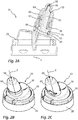
- Fig. 1A and 1B show an overall view of a dispenser 100 according to the invention in a sectional and uncut representation.
- the relationships explained below for different embodiments of the discharge head 10 of this dispenser 100 apply. Details of two possible embodiments of the dispensing head 10 are subsequently described with reference to FIG Fig. 2A to 2I and Figs. 3A to 3H are explained.
- An inventive dispenser 100 has a pressure accumulator 110 whose outer surfaces are formed by a metallic body 118 and a cover 120.
- an outlet valve 112 is attached, which can be opened by depressing a valve stub 114 against the force of a valve spring 116, so that the liquid flows into the discharge head 10.
- the dispenser 100 has at the discharge head 10 a slender, elongated nasal applicator 12 whose main direction of extension is set in relation to the main extension direction 3 of the pressure accumulator 110.
- the nasal applicator 12 is for insertion into a nostril of a User provided.
- Other types of applicator may be provided here depending on the application instead of the Nasalapplikators 12.
- the discharge head 10 is snapped onto the pressure accumulator 110 in the region of a crimp connection between the body 118 and the cover 120, for which purpose a coupling device is provided on a base 20 of the discharge head.
- the base 20 of the discharge head 10 is integrally connected to the majority of the functional elements of the discharge head 10.
- an actuating handle 30 with actuating surface 32 is integrally formed on the base 20 via a plastic bridge 28.
- plunger 40 is integrally formed, which is inserted into the outlet valve 112 of the pressure accumulator 110 for the purpose of actuation and for the purpose of the inflow of liquid.
- the mecanicalapplikators 12 of the discharge head 10 is formed integrally with the actuating handle 30, in this regard, a further explained below difference between the designs of Fig. 2A to 2I and the Figs. 3A to 3H consists.
- the mecanicbauteit 50 includes an outer sleeve portion 56 and an inner pin 52nd
- a component of the discharge head 10 which is separate from this composite component is the outer component 60 of the nasal applicator 12, at the end face of which an end wall is interrupted by a discharge opening 98.
- the outer member 60 is pushed onto the inner member 50 and in the design of the Fig. 2A to 2I positively secured to the inner member 50, as will be explained below.
- the actuating handle 30 of the dispenser 100 is pivotable in the direction of the arrow 6 due to the deformability of the plastic bridge 28, so that the Nasalapplikator 12 and the plunger 40 are pivoted with.
- the outlet valve 112 is opened and liquid flows through the inner channel 90 of the plunger 40 upwards, then enters an inflow region 58 between the central pin 52 and the sleeve portion 56 of the inner member 50 of the Nasalapplikators 12 and from there through an applicator channel 92 defined jointly by the inner component 50 and the outer component 60 is conveyed to the discharge opening 98, from where the liquid can be discharged.
- the outer component For sealing the components 50, 60 against each other, the outer component a sleeve 66, the outside of which rests liquid-tight on the inside sealing surface of the sleeve portion 56.
- the outer member 60 is formed as a limited relatively movable outer member 60.
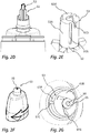
- Fig. 2A to 2I show in detail a first embodiment of a discharge head according to the invention, according to the Fig. 1A and 1B which is to be attached to a pressure accumulator 110 to form a dispenser 100.
- the discharge head 10 the two components already described, namely - as in Fig. 2A clearly visible - the first component, which forms the base 20, the actuating handle 30 with actuating surface 32 and integrally an inner component 50 of the applicator, and the second component, the outer member 60, which is pushed onto the inner component 50 of the applicator and here in the range of Clamping surfaces 55, 65 is locked.
- Figs. 2B and 2C can be switched between different discharge characteristics, namely present between a discharge of the liquid in the form of a spray jet on the one hand and the discharge in the form of an atomized jet on the other.
- the switching of the configurations takes place in that the outer component 60 is rotated relative to the inner component 50 by 180 ° about the axis 2. An axial displacement of inner component 50 and outer member 60 does not take place here.
- FIGS. 2D to 2G clarify this.
- Fig. 2E shows the front area 53 of the inner component 50.
- This has an initial circular cylindrical basic shape whose dimensions relative to the diameter of an end face 53B correspond to the dimensions of the corresponding distal interior 63 of the outer member 60, so that the End region 53 is inserted under circumferential and frontal sealing system in the distal interior 63.
- axially extending supply grooves 97A are provided, which extend to the end face 53B. It is a total of three supply grooves 97A at a distance of 120 ° to each other. Offset by about 30 ° thereto, three radial Zuströmnuten 97 D are provided in the end face 53 B of the end portion 53 of the inner member 50, which are also spaced apart by 120 ° and each extending to the cylindrical outer surface 53 A.
- three grooves 97C offset by 120 ° from each other are provided on the outer component in an inner circumferential surface 63A, which do not extend to the front-side inner surface 63B, but shortly before each of them Find the end.
- the front-side inner surface 63B itself three tangentially oriented Zuströmnuten 97B are provided which open tangentially into a swirl chamber 96 and are also spaced from each other by 120 °.
- This groove configuration is provided in order to open and close different fluid paths as a function of the rotational position of the outer component 60 relative to the inner component 50.
- the Fig. 2H shows that configuration in which the outer member 60 is rotated relative to the inner member 50 so that intended, an atomized jet is to be discharged.
- the supply grooves 97C are arranged such that liquid at its end can flow into the radial inflow grooves 97D and thus reach the discharge opening 98 without forming a twist. Meanwhile, in this rotational position, the tangential grooves 97B are not supplied with liquid since they are arranged rotatably offset from their supply grooves 97A.
- the groove design described thus makes it possible to provide very functionally reliable and mutually sealed fluid paths both for the formation of a spray jet and for the formation of a jet available, the paths can be opened and closed only by a rotational movement of the outer member relative to the inner member.
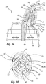
- Fig. 3A to 3G together with a variant of Fig. 3H has a modification, which serves in particular the purpose of ensuring the tightness in the region of the end face 53B and to prevent by a switching valve to prevent a discharge particularly safe.
- FIGS. 3A and 3B show the position of inner member 50 and outer member 60 in a position to produce a spray jet.
- 3C and 3D show the position of inner member 50 and outer member 60 in a position to produce an un-atomized jet.
- the inner member 50 is not integrally connected to the base 20 and the actuating handle 30, but instead formed as a separate component 50 which is axially slid onto a pin 82 which is part of a guide member 80, which in this particular case integral with the actuating surface 32 and the base 20 is executed.
- the guide member 80 could be formed separately from the components 32 and 20 and attached to one of them only fixed.
- a spring means 70 which is formed by clamping surfaces 65, 85 which are provided in this case on the guide member 80 and the outer member 60 and the outer member 60 press the front side against the inner member 50.
- the interior component 50 which is in Fig. 3F again shown separately, has a sleeve structure open on both sides. With its end pointing away from the discharge opening 98, it is pushed onto the said pin 82 of the guide component 80. It is by ribs 87 and recesses 57 in the in Fig. 3B and 3D clarified way created an anti-rotation.
- the inner member 50 is thus secured against rotation, but in principle axially displaceable, attached to the guide member 80.
- the inner component 50 has at its end a piston surface 54 and abuts with an outer side sealingly against a sliding surface 84 of a sleeve portion 86 of the guide component 80.
- the inner component 50 At the opposite end of the inner component 50, this merges into an end region 53 which, in terms of its structure and in particular of the supply grooves 97A and 97D, corresponds to the structure Fig. 2E equivalent.
- the inner component In order to be able to convey liquid here, the inner component is also designed to be open in this direction and has an opening 59 for this purpose. Beyond this opening, a further piston surface 51 is provided, which abuts the outside on a sliding surface 61 of the outer component 60.
- This second piston surface 51 or its effective cross section is smaller than the piston surface 54 or its effective cross section.
- Fig. 3B and 3D illustrate further locking positions of the inner member 50 and the outer member 60 to each other, wherein in the case of the design of Figs. 3A to 3H
- These detent positions are made possible by outer recesses 89 on the sleeve portion 86 of the guide member 80 and inwardly facing latching webs 69 on the outer member 60.
- the locking webs 69 in the wells 89th are indented, it requires an increased force to rotate the outer member 60 relative to the inner member 50 and the guide member 80. If the components are rotated relative to one another, snap the locking webs 69 into the recesses 89 and thus signal the user that it is a special rotational position.
- Fig. 3B and 3D which are the position for discharging a spray jet or a jet
- two other positions are possible, which are rotated by 90 ° contrast. In these positions, the discharge head is locked, as will be explained below.
- Fig. 3E shows a further sectional view. It can be seen here that the outer component 60 is provided with inwardly pointing radial ribs 62. These have a shape with which they form said locking webs 69 for forming the locking positions in an upper region. In contrast, a lower region 67 bears against the clamping surface 85 on the outside. The effect of this lower portion 67 is that the outer member 60 is only slightly deformable and therefore there is no risk that it dissolves under the action of fluid pressure from the inner member 50 and the guide member 80.
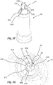
- Figs. 3F and 3G show similar to the Figures 2E and 2G the inflow grooves 97B, 97D and the supply grooves 97A, 97C. Their operation corresponds to that already explained:
- the liquid is passed either along a first liquid path through the supply grooves 97A into the Zutrömnuten 97B or along a second liquid path through the supply grooves 97C in the Zuströmnuten 97D. If none of these liquid paths is open, the liquid can not reach the discharge opening 98.
- a switching valve 99 is provided, which is formed by two stages 99A, 99C in the outer member 60 and inner member 50 and by therein provided interruptions 99B, 99D. In two 180 ° spaced apart rotational positions, namely precisely those rotational positions for the discharge as a jet or spray, the interruptions 99 B, 99 D are aligned such that liquid can flow through the switching valve 99. In all other positions, the switching valve 99 stops the supply of liquid to the supply grooves 97A, 97C.
- the piston-like configuration of the inner component 50 is suitable for permanently pressing it in the direction of the discharge opening 98 when fluid pressure is applied.
- a special degree of tightness between the abutting surfaces 53B, 63B is created.
- the special tightness ensures that the application of a jet as well as a spray jet in particularly good quality is possible. Liquid only passes through the grooves 97A-97D to the discharge port 98, but not through an unwanted gap between the end surface 53B and the front-side inner surface 63B.
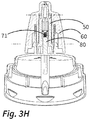
- Fig. 3H shows a slightly modified variant of the embodiment of Fig. 3A to 3G ,
- an additional spring device 71 in the form of a helical compression spring is provided between the guide component 80 and the inner component 50, which presses the inner component 50 permanently against the outer component 60 on the front side.
- the piston-like action of the inner component 50 can be dispensed with. Preferably, however, this remains despite the spring device 71 is obtained.
Landscapes
- Health & Medical Sciences (AREA)
- Engineering & Computer Science (AREA)
- Animal Behavior & Ethology (AREA)
- General Health & Medical Sciences (AREA)
- Veterinary Medicine (AREA)
- Anesthesiology (AREA)
- Biomedical Technology (AREA)
- Heart & Thoracic Surgery (AREA)
- Hematology (AREA)
- Life Sciences & Earth Sciences (AREA)
- Public Health (AREA)
- Mechanical Engineering (AREA)
- Bioinformatics & Cheminformatics (AREA)
- Pulmonology (AREA)
- Chemical & Material Sciences (AREA)
- Dispersion Chemistry (AREA)
- Otolaryngology (AREA)
- Vascular Medicine (AREA)
- Containers And Packaging Bodies Having A Special Means To Remove Contents (AREA)
- Infusion, Injection, And Reservoir Apparatuses (AREA)
Abstract
Description
- Die Erfindung betrifft einen Austragkopf für die Applikation pharmazeutischer Flüssigkeiten, insbesondere für die nasale Applikation von pharmazeutischen Flüssigkeit aus einem Druckspeicher, welcher über ein Auslassventil mit einem Ventilstutzen verfügt, der gegen eine Federkraft zum Öffnen des Auslassventils kraftbeaufschlagbar ist. Die Erfindung betrifft weiterhin auch einen Spender mit einem solchen Austragkopf.
- Ähnliche Austragköpfe und Spender sind beispielsweise aus der
DE 102012200545 A1 bekannt. Die in dieser Schrift offenbarten Austragköpfe verfügen über ein Außengehäuse, welches einerseits die Basis zur Anbindung an einem Druckspeicher beinhaltet und andererseits die Außenschale eines Nasalapplikators mitsamt Austragöffnung bildet. In den länglichen Nasalapplikator ist ein Innenbauteil eingeschoben, welches gemeinsam mit der Außenschale der Fluidführung von Flüssigkeit zur Austragöffnung dient. - Auch aus dem US Design Patent mit der Publikationsnummer
US D 659,531 S - Die genannten Austragköpfe werden für den Vertrieb von Medikamenten mit vergleichsweise geringem Verkaufspreis verwendet. Es ist daher erforderlich, dass die Herstellung der Austragköpfe preisgünstig möglich ist. Die diesbezügliche vorteilhafte einstückige Gestaltung des Außengehäuses mit Basis und Nasalapplikator ist zur Erzielung geringer Kosten gut geeignet. Allerdings sind auch Nachteile gegeben. Das Zuführen des flüssigen Kunststoffes im Rahmen des Spritzguss-Vorgangs erfolgt üblicherweise im Bereich der Basis. Die Austragöffnung ist daher vergleichsweise weit vom Zuführpunkt entfernt, was zu einer mitunter nicht zufriedenstellenden Fertigungsgenauigkeit an der Austragöffnung und an Fluidleitflächen stromaufwärts der Austragöffnung führt. Dies ist von Nachteil, da hierdurch das Austragverhalten der Flüssigkeit von Spender zu Spender variieren kann und nicht mehr dem beabsichtigten Austragverhalten entspricht.
- Aufgabe der Erfindung ist es daher, einen gattungsgemäßen Spender dahingehend weiterzubilden, dass eine hohe Fertigungsgenauigkeit im Bereich der Austragöffnung erzielt wird, ohne die Komplexität der Fertigung relevant zu erhöhen.
- Die Erfindung betrifft einen Austragkopf, der insbesondere für die nasale Applikation von pharmazeutischen Flüssigkeiten aus einem Druckspeicher vorgesehen ist, welcher über ein Auslassventil mit einem Ventilstutzen verfügt, der gegen eine Federkraft zum Öffnen des Auslassventils kraftbeaufschlagbar ist.
- Ein erfindungsgemäßer Austragkopf verfügt über einen Applikator, insbesondere in Form eines Nasalapplikators, an dessen Ende eine Austragöffnung vorgesehen ist, die durch einen Applikatorkanal des Nasalapplikators hindurch mit einem Einlass des Applikators und damit mittelbar mit dem Flüssigkeitsspeicher verbunden ist. Unter der Austragöffnung im Sinne der Erfindung ist das Ende des Applikatorkanals zu verstehen, also der Übergangspunkt, an dem die druckbeaufschlagte Flüssigkeit in eine äußere Umgebung unter Umgebungsdruck abgegeben wird und dort je nach Art des Austritts durch die Austragöffnung als freier Jet oder als Sprühstrahl vorliegt. Die Austragöffnung weist vorzugsweise eine minimale Querschnittsfläche von weniger als 4 mm2 auf, insbesondere von weniger als 2 mm2.
- Der erfindungsgemäße Applikator verfügt weiter über ein Innenbauteil und ein Außenbauteil. Das Außenbauteil ist als vom Innenbauteil getrenntes Bauteil vorgesehen und unmittelbar oder mittelbar am Innenbauteil in einer Weise angebracht, durch die es rein rotativ gegenüber dem Innenbauteil beweglich ist. Diese rein rotative Beweglichkeit kann durch eine entsprechende axial sperrende Kopplung von Innenteil und Außenteil bewirkt sein. Sie kann jedoch auch dadurch bewirkt sein, dass das Innenbauteil zwar grundsätzlich gegenüber dem Außenbauteil axial beweglich ist, jedoch reibschlüssig an diesem gehalten ist und keinerlei Relativkraftbeaufschlagung durch den Benutzer von außen möglich ist, mittels derer Innenbauteil und Außenbauteil gegeneinander axial verlagert werden. Dies wird im Weiteren noch näher erläutert.
- Die Ausbildung des drehbaren Außenbauteils als von einer Basis des Austragkopfes separates Bauteil ist von Vorteil, da hierdurch eine Austauschbarkeit des Außenbauteils erzielt werden kann, die aus Hygienegründen von Vorteil ist. Insbesondere die Austragöffnung, an der nach der Nutzung Flüssigkeit verbleiben kann, kann schnell verkeimen. Durch einen Austausch des Außenbauteils werden alle oder zumindest besonders gefährdete Bereiche ausgetauscht. Auch die Anpassung des Austragkopfes an eine bestimmte Zielgruppe ist durch das separate Außenbauteil möglich. So kann insbesondere eine erwachsenengerechte bzw. kindgerechte Gestaltung durch die Wahl des passenden Außenbauteils erzielt werden. Dabei ist sowohl möglich, dass bereits herstellerseitig eine zielgruppenspezifische Anpassung erfolgt, als auch, dass mehrere Außenbauteile an den Endkunden mitgeliefert werden, so dass er selbst die Anpassung einmalig oder fallweise vornehmen kann.
- Im Falle einer Gestaltung des Applikators als Nasalapplikator wird dieser bestimmungsgemäß in ein Nasenloch des Nutzers eingeführt. Zu diesem Zweck handelt es sich um einen länglichen, schlanken Applikator, der vorzugsweise eine sich zum distalen Ende und der Austragöffnung verjüngende Formgebung aufweist. Vorzugsweise ragt der Nasalapplikator ausgehend vom Niveau einer Betätigungsfläche mindestens 20 mm hervor. Seine frei von der Basis bzw. der Betätigungsfläche hervorstehende Länge ist vorzugsweise mindestens um Faktor 2, insbesondere vorzugsweise mindestens um Faktor 2,5, größer als der maximale Durchmesser des Nasalapplikators.
- Vorzugsweise verfügt der Austragkopf über eine Basis und eine daran vorgesehene Kopplungseinrichtung, mittels derer der Austragkopf am Druckspeicher befestigbar ist. Er verfügt weiterhin vorzugsweise über eine verlagerbare Betätigungsfläche, die gegenüber der genannten Basis verlagerbar ist, und an der ein als Hohlrohr ausgestalteter Stößel vorgesehen ist, der zum Zwecke der Kraftbeaufschlagung des Ventilstutzens des Druckspeichers gemeinsam mit der Betätigungsfläche verlagerbar ist. Vorzugsweise ist die Betätigungsfläche mit einer Strukturierung, beispielsweise einer Riffelung versehen. Der genannten Applikator erstreckt sich von der Betätigungsfläche aus nach außen.
- Die Basis eines erfindungsgemäßen Austragkopfes ist jener Teil, der bestimmungsgemäß am Druckspeicher angekoppelt wird. Hierfür ist die Kopplungseinrichtung vorgesehen, die insbesondere vorzugsweise über angeformte Rastkanten auf dem Druckspeicher aufgeschnappt wird. Die Basis verfügt hierfür vorzugsweise über eine ringartige Struktur mit nach innen weisenden Rastnasen. Bei bevorzugt mit einem erfindungsgemäßen Austragkopf verwendeten Druckspeichern ist eine Crimp-Verbindung zwischen einem Deckel und einem Mantel vorgesehen, welche vorzugsweise zum Aufschnappen der Rastnasen verwendet wird.
- Der Applikator, insbesondere in Form eines Nasalapplikators, verfügt erfindungsgemäß über ein Innenbauteil, welches vorzugsweise einstückig mit der Betätigungsfläche und/oder der Basis verbunden ist oder axial verschieblich und rotativ fixiert an einem Führungsbauteil angebracht ist, welches seinerseits einstückig mit der Betätigungsfläche und/oder der Basis verbunden ist. Weiterhin verfügt er über ein Außenbauteil, welches als vom Innenbauteil getrenntes Bauteil ausgebildet ist und das Innenbauteil umgebend an diesem angebracht ist. Die Austragöffnung ist als Durchbrechung des Außenbauteils vorgesehen. Ein zur Austragöffnung führender Applikatorkanal ist gemeinsam durch das Außenbauteil und das Innenbauteil begrenzt.
- Das Außenbauteil und die Betätigungsfläche des Austragskopfes weisen vorzugsweise unterschiedliche Farbgebungen und/oder unterschiedliche Materialen auf. Die Zweifarbigkeit von Basis und Außenbauteil kann insbesondere zum Zwecke der ästhetischen Verbesserung genutzt werden, jedoch auch, um den Austragkopf an eine unternehmensspezifische typische Farbgebung anzupassen. Die Verwendung verschiedener Materialien gestattet es darüber hinaus, jeweils ideal angepasste Materialien für das Außenbauteil und die Basis mitsamt Betätigungshandhabe zu wählen. So könnte das Außenbauteil beispielsweise aus einem Material gefertigt sein, welches durch Beschichtung oder inhärente Materialeigenschaften Bakterienwachstum verhindert oder welches in Kontakt mit der Haut des Nutzers als haptisch angenehm empfunden wird, während das Hauptbauteil mit Basis und Betätigungshandhabe aus einem anderen Material bestehen kann.
- Vorzugsweise ist die Betätigungsfläche schwenkbeweglich an der Basis angebracht, insbesondere vorzugsweise durch eine einstückig die Basis und die Betätigungsfläche verbindende Kunststoffbrücke, die als Schwenkgelenk agiert. Insbesondere von Vorteil ist es weiterhin, wenn auf einer der Kunststoffbrücke gegenüberliegenden Seite der Betätigungsfläche im Lieferzustand eine Sicherungsbrücke vorgesehen ist, die die Betätigungsfläche und die Basis einstückig verbindet und bei Erstbetätigung bestimmungsgemäß bricht. Die genannte einstückige Gestaltung mit verformbarer Kunststoffbrücke als Gelenk ist im Sinne eines Aufbaus aus wenigen Einzelteilen von Vorteil. Die Betätigungsfläche ist abseits der Kunststoffbrücke gegenüber der Basis durch einen Schlitz freigeschnitten, so dass sie beweglich ist. Durch die Sicherungsbrücke wird erreicht, dass es vor Inbetriebnahme nicht zu einem ungewollten Austrag von Flüssigkeit kommt, da die Inbetriebnahme zum Zwecke des Brechens dieser Sicherungsbrücke eine stärkere Kraftbeaufschlagung erfordert.
- Eine durch die Austragrichtung der Austragöffnung und/oder durch eine die Rotationsmittelachse des Außenbauteils gegenüber dem Innenbauteil definierte Achse schließt vorzugsweise mit einer Aufsetzrichtung des Austragkopfs auf einen Druckspeicher einen Winkel zwischen 5° und 85° ein, vorzugsweise einen Winkel zwischen 10° und 50°. Diese Anwinkelung ist bei gattungsgemäßen Austragköpfen üblich. Sie gestattet eine vorteilhafte Verwendung, bei der der Druckspeicher, dessen Haupterstreckungsrichtung vorzugsweise mit der Aufsetzrichtung übereinstimmt, leicht angewinkelt gehalten werden kann und der Nasalapplikator dann in passendem Winkel in ein Nasenloch eingeschoben werden kann. Bei einem erfindungsgemäßen Austragkopf ist vorzugsweise weiterhin vorgesehen, dass die Betätigungsfläche und der Nasalapplikator nebeneinander angeordnet sind, so dass eine asymmetrische Formgebung des Austragkopfes gegeben ist.
- Die Austragöffnung eines erfindungsgemäßen Austragkopfes ist als Durchbrechung des Außenbauteils vorgesehen und innenseitig von einer stirnseitigen Innenfläche umgeben. Der stirnseitigen Innenfläche gegenüberliegend ist eine Stirnfläche des Innenbauteils vorgesehen, welche flächig an der stirnseitigen Innenfläche anliegt.
- An der stirnseitigen Innenfläche des Außenbauteils und/oder an der Stirnfläche des Innenbauteils sind erfindungsgemäß mindestens zwei Zuströmkanäle in Form von Zuströmnuten ausgebildet, die in Abhängigkeit einer Drehstellung des Außenbauteils zum Innenbauteil mit einem Zuströmbereich stromaufwärts der Zuströmnuten und somit dem Flüssigkeitsspeicher verbunden oder hiervon getrennt werden.
- Die genannten Zuströmnuten verbinden somit den Zuströmbereich, in den Flüssigkeit aus dem Flüssigkeitsspeicher zunächst strömt, mit der Austragöffnung. Dabei ist es durch mindestens zwei Zuströmnuten mit unterschiedlicher Gestaltung möglich, die Austragcharakteristik der durch die Austragöffnung hindurch abgegebenen Flüssigkeit zu beeinflussen. Wird in einer ersten Drehstellung eine erste der Zuströmnuten durchströmt, während die zweite Zuströmnut verschlossen ist, so bestimmt die erste Zuströmnut und deren Formgebung, Ausrichtung und Drosselwirkung die Austragcharakteristik. Handelt es sich beispielsweise um eine radial ausgerichtete Zuströmnut, so führt dies nicht zu einer Verwirbelung und die Flüssigkeit wird als so genannter Jet ausgetragen. Wird in einer zweiten davon abweichenden Drehstellung die zweite Zuströmnut statt der ersten geöffnet, so bestimmt deren Formgebung, Ausrichtung und Drosselwirkung die Austragcharakteristik. Handelt es sich beispielsweise um eine nicht-radial ausgerichtete Nut, insbesondere eine Tangentialnut, die zur Radialrichtung angewinkelt ausgerichtet ist, so kann die Flüssigkeit einen Drall erhalten, der beim Austrag durch die Austragöffnung die Ausbildung eines Sprühstrahls begünstigt.
- Grundsätzlich kann das durch Drehen des Außenbauteils bewirkte Öffnen und/oder Schließen der Zuströmnuten auch alleine dafür genutzt werden, unterschiedliche Flüssigkeitsmengen auszutragen, also quasi eine einstellbare Drosselwirkung zu erzielen. Insbesondere von Vorteil ist es jedoch, wenn Zuströmnuten zweier unterschiedlicher Arten vorgesehen sind, nämlich mindestens eine im Wesentlichen radial ausgerichtete Radialnut und mindestens eine demgegenüber bezogen auf die Austragöffnung angewinkelte Tangentialnut, deren mittlere Erstreckungsrichtung als nicht fluchtend zur Austragöffnung vorgesehen ist. Die Radialnut oder die Radialnuten dienen dabei der Erzeugung des bereits genannten Jets, während die Tangentialnut oder Tangentialnuten der Bildung eines Wirbels und damit eines Sprühstrahl dienen. Insbesondere vorzugsweise sind von den Radialnuten und/oder den Tangentialnuten jeweils mehrere vorgesehen, vorzugsweise jeweils mindestens drei, die insbesondere vorzugsweise über den Umfang gleichverteilt sind, um einen gleichmäßigen und im Wesentlichen rotationssymmetrischen Austrag zu bewirken.
- Die mindestens zwei Zuströmnuten, insbesondere also die mindestens eine Radialnut und die mindestens eine Tangentialnut, sind beide im Bereich der stirnseitigen Innenfläche des Außenbauteils und der Stirnfläche des Innenbauteils vorgesehen, wobei sie vorzugsweise derart getrennt angeordnet sind, dass keine Flüssigkeit ungewollt von einer Zuströmnut in die jeweils andere Zuströmnut gelangen kann und entlangdererzur Austragöffnung strömen kann.
- Um die Zuströmnuten vorteilhaft gegeneinander isolieren zu können, ist eine Gestaltung von Vorteil, bei der mindestens eine Zuströmnut in der stirnseitigen Innenfläche des Außenbauteils und mindestens eine Zuströmnut in der Stirnfläche des Innenbauteils vorgesehen ist. Es werden somit beide aneinander angepressten Flächen, die stirnseitige Innenfläche des Außenbauteils und die Stirnseite des Innenbauteils, zur Anordnung der Zuströmnuten genutzt. Hierdurch wird deren sichere Isolierung voneinander auch bei geringer Baugröße ermöglicht. Insbesondere, wenn Radial- und Tangentialnuten vorgesehen sind und vor allem wenn jeweils mehrere Radial- und Tangentialnuten vorgesehen sind, ist die Anordnung der Zuströmnuten auf die stirnseitige Innenfläche und die Stirnfläche von Vorteil.
- Vorzugsweise liegen das Innenbauteil und das Außenbauteil nicht nur im Bereich der stirnseitigen Innenfläche und der Stirnfläche dicht aneinander an, sondern auch im Bereich einer an die stirnseitige Innenfläche des Außenbauteils angrenzenden zylindrischen oder im Wesentlichen zylindrischen Innenfläche und einer an die Stirnfläche des Innenbauteils angrenzenden zylindrischen oder im Wesentlichen zylindrischen Außenfläche.
- Dabei ist mindestens in einer der genannten beiden zylindrischen oder im Wesentlichen zylindrischen Flächen eine Versorgungsnut vorgesehen, durch die hindurch mindestens eine Zuströmnut mit Flüssigkeit aus dem Zuströmbereich versorgbar ist. Insbesondere vorzugsweise sind in den Flächen mehrere solche Versorgungsnuten vorgesehen, die je nach Drehstellung unterschiedliche Zuströmnuten mit Flüssigkeit versorgen.
- Wie bereits in Hinblick auf die Stirnfläche und die stirnseitige Innenfläche in Bezug auf die Zuströmnuten erörtert, ist vorzugsweise auch im Bereich der zylindrischen Innenfläche und der zylindrischen Außenfläche vorgesehen, dass sowohl in der Innenfläche als auch in der Außenfläche Versorgungsnuten vorgesehen sind. Es hat sich gezeigt, dass so ein besonders vorteilhafter Aufbau möglich ist, mittels dessen die Flüssigkeitszufuhr zu den unterschiedlichen Zuströmnuten zugelassen und unterbrochen werden kann. Vorteilhafterweise verlaufen alle Strömungspfade vom Zuströmbereich zur Austragöffnung jeweils partiell durch eine Nut im Innenbauteil und partiell durch eine Nut im Außenbauteil.
- Es kann ein erster Flüssigkeitspfad vorgesehen sein, der im Falle der entsprechenden Drehstellung des Außenbauteils gegenüber dem Innenbauteil durch einen in der zylindrischen Außenfläche des Innenbauteils vorgesehene Versorgungsnut verläuft, wobei sich diese Versorgungsnut bis zur Stirnfläche des Innenbauteils erstreckt. Dieser Flüssigkeitspfad verläuft dann vorzugsweise weiter in eine an der stirnseitigen Innenfläche des Außenbauteils vorgesehene Zuströmnut bis zur Austragöffnung. Ist das Außenbauteil demgegenüber aber verdreht, so endet dieser Flüssigkeitspfad im Bereich der durch die Versorgungsnut durchbrochenen Stirnfläche, da er von der stirnseitigen Innenfläche des Außenbauteils blockiert wird.
- In ähnlicher Weise kann ein Flüssigkeitspfad bzw. ein zweiter Flüssigkeitspfad durch eine Versorgungsnut in derzylindrischen Innenfläche des Außenbauteils verlaufen, sich jedoch dabei nicht bis auf Höhe der Stirnfläche des Innenbauteils erstrecken. Stattdessen kann dieser Flüssigkeitspfad dann bei entsprechender Drehstellung des Außenbauteils gegenüber dem Innenbauteil weiter durch eine Zuströmnut verlaufen, die sich auf der Stirnfläche des Innenbauteils bis zur angrenzenden zylindrischen Außenfläche erstreckt.
- Die jeweiligen Zuströmnuten der beiden genannten Flüssigkeitspfade sind dabei derart angeordnet, dass je nach Drehstellung immer nur ein Teil der Zuströmnuten mit ihrer jeweiligen Versorgungsnut verbunden sind, während ein anderer Teil der Zuströmnuten von ihrer jeweiligen Versorgungsnut getrennt ist. Beide Flüssigkeitspfade verlaufen im geöffneten Zustand vorzugsweise sowohl durch Nuten im Innenbauteil als auch durch Nuten im Außenbauteil.
- Von Vorteil ist es, wenn das Innenbauteil und das Außenbauteil in einer Drehstellung derart angeordnet sind, dass alle Zuströmkanäle zur Austragöffnung unterbrochen sind und der Austragkopf somit verschlossen ist. Bei einem Austragkopf mit zwischen zwei Endlagen limitierter Drehbeweglichkeit des Außenbauteils gegenüber dem Innenbauteil ist es von Vorteil, wenn in beiden Endlagen Flüssigkeitspfade mit unterschiedlicher Austragcharakteristik geöffnet sind und in einer Zwischenlage der Austragkopf in der genannten Art verschlossen ist.
- Demgegenüber noch von Vorteil ist es, wenn im Zuströmbereich stromaufwärts der genannten Zuströmnuten und gegebenenfalls vorzugsweise auch der genannten Versorgungsnuten ein Schaltventil vorgesehen ist, welches in Abhängigkeit der Drehstellung des Außenbauteils zum Innenbauteil die Flüssigkeitszufuhr zu den Zuströmnuten unterbricht.
- Mit einer solchen Gestaltung wird erreicht, dass nicht erst im Bereich der Stirnfläche und der stirnseitigen Innenfläche oder im daran angrenzenden zylindrischen Bereich der Versorgungsnuten die Flüssigkeit am Austritt durch die Austragöffnung gehindert wird, sondern bereits vor dem Einströmen in die Zuströmnuten bzw. die Versorgungsnuten an einem separaten Schaltventil. Dieses Schaltventil ist somit insbesondere vorzugsweise vor jener Stelle in den Flüssigkeitspfaden angeordnet, an dem sich die Flüssigkeitspfade für unterschiedliche Austragcharakteristiken voneinander trennen.
- Das Schaltventil ist vorzugsweise durch eine Stufe am Innenbauteil und am Außenbauteil vorgesehen, also im Bereich eines Querschnittswechsels, wobei in den jeweiligen Stufen ein Ventilkanal vorgesehen ist. Nur wenn die Ventilkanäle in einer definierten Drehstellungen von Innenbauteil und Außenbauteil miteinander fluchten, kann Flüssigkeit hindurchströmen. Vorzugsweise sind an mindestens einem der beiden Bauteile, vorzugsweise an beiden Bauteilen, zwei solche Ventilkanäle vorgesehen, so dass in zwei definierten Drehstellungen Flüssigkeit zuströmen kann. Diese beiden Drehlagen können dann jene sein, die aufgrund der Gestaltung der Versorgungsnuten und Zuströmnuten unterschiedliche Austragcharakteristiken, insbesondere als Spray und als Jet, verursachen.
- Um den ungewollten Wechsel von Flüssigkeit zwischen den Zuströmnuten zu unterbinden, also insbesondere einen Flüssigkeitsstrom aus einer Tangentialnut in einer Radialnut oder aus einer Radialnut in eine Tangentialnut, liegen die Stirnflächen des Innenbauteils und die stirnseitige Innenfläche des Außenbauteils dichtend aneinander an. Um trotz der Toleranzen im Fertigungsverfahren der vorzugsweise als Kunststoffteile gebildeten Bauteile, des Innenbauteils und des Außenbauteils, zu verhindern, dass die Stirnfläche und die stirnseitige Innenfläche sich voneinander abheben, besteht eine bauliche Möglichkeit darin, das Innenbauteil und das Außenbauteil mit einer Federeinrichtung zu versehen, mittels derer sie gegeneinander gepresst werden. Unter einer Federeinrichtung wird dabei eine elastisch verformte Struktur verstanden, deren Rückstellkraft die Stirnfläche und die stirnseitige Innenfläche gegeneinander presst.
- Besonders vorteilhaft ist dabei eine Gestaltung, bei der das Außenbauteil und das Innenbauteil über schräggestellte Spannflächen verfügen, die durch elastische Verformung des Innenbauteils oder insbesondere des Außenbauteils in einer Radialrichtung aneinander angepresst werden und hierdurch mittelbar das Außenbauteil und das Innenbauteil aneinander anpressen. Hierbei wird ausgenutzt, dass das Außenbauteil das Innenbauteil umgibt und durch dieses elastisch radial aufgeweitet sein kann. Die entsprechende Rückstellkraft wird im Bereich der schräggestellten Spannflächen umgelenkt, so dass in der gewünschten Weise die Stirnfläche des Innenbauteils und die stirnseitige Innenfläche des Außenbauteils aneinander gepresst werden, so dass Flüssigkeit nicht von einer Zuströmnut in eine andere gelangen kann.
- Von besonderem Vorteil ist es dabei, wenn das Innenbauteil und/oder das Außenbauteil eine von der Kreisform abweichende Formgebung der Spannflächen oder anderweitiger aufeinander zu weisender Kontaktflächen aufweisen, so dass bei einer Rotation des Außenbauteils gegenüber dem Innenbauteil mindestens eines der Bauteile eine variierende Verformung zeigt, die insbesondere in zwei Endlagen minimal ist und ggf. einer weitere Zwischenlage. Hierdurch ergibt sich eine besondere Stabilität der beiden Endlagen, die vorzugsweise zwei Ausbringungsarten - insbesondere als Jet und als Sprühstrahl - definieren. Eine Zwischenlage kann dem oben beschriebenen Schließzustand zugeordnet sein. Ein Verdrehen aus den Endlagen und ggf. aus der genannten Zwischenlage, geht mit einer Vergrößerung der Verformung eines der Bauteile, insbesondere des Außenbauteils, einher, so dass ein solches Verdrehen kaum unbeabsichtigt stattfinden kann.
- Bei einer Variante der Erfindung ist das Innenbauteil des Applikators einstückig mit der Betätigungsfläche verbunden. Durch eine solche Ausgestaltung lässt sich ein Austragkopf erzielen, der aus nur zwei Bauteilen besteht, nämlich einem ersten Bauteil, umfassend die Basis, die Betätigungshandhabe mit Betätigungsfläche sowie das Innenbauteil des Nasalapplikators, wobei mindestens die Betätigungshandhabe durch Materialverformbarkeit gegenüber der Basis verlagerbar ist, und einem zweiten Bauteil, welches das Außenbauteil des Nasalapplikator bildet. Es ist somit eine sehr kostengünstige Bauweise möglich.
- Bei einer alternativen Variante weist der Austragkopf ein Führungsbauteil auf, welches vorzugsweise einstückig mit der Betätigungsfläche und/oder der Basis ausgebildet ist. Das Innenbauteil ist dagegen bei dieser Variante nicht einstückig mit Betätigungsfläche oder Basis verbunden, sondern axial verschieblich und rotativ fixiert am Führungsbauteil angebracht. Das Außenbauteil ist ebenfalls am Führungsbauteil befestigt, allerdings drehbar.
- Bei dieser alternativen Variante sind also das Außenbauteil und das Innenbauteil nicht zwingend unmittelbar aneinander axial fixiert, sondern vor allem über das Führungsbauteil, welches vorzugsweise einstückig mit der Basis ausgebildet ist. Obwohl das Innenbauteil und das Außenbauteil aufgrund der axialen Beweglichkeit des Innenbauteils gegenüber dem Führungsbauteil grundsätzlich axial gegeneinander verlagerbar sind, findet eine solche Verlagerung nicht statt. Die axiale Verlagerbarkeit dient stattdessen dem Zweck, das Innenbauteil mit besonders hoher Kraft gegen das Außenbauteil zu pressen, um Leckage im Bereich der Zuströmkanäle zu verhindern.
- Hierfür ist vorzugsweise vorgesehen, dass das Innenbauteil und das Führungsbauteil gemeinsam eine Druckkammer begrenzen, wobei das Innenbauteil eine zur Druckkammer gewandte Kolbenfläche aufweist, deren Kraftbeaufschlagung durch Flüssigkeitsdruck in der Druckkammer in Richtung der Austragöffnung wirkt. Als Kolbenfläche wird die Querschnittsfläche angesehen, auf die der Flüssigkeitsdruck in Richtung der Austragöffnung wirkt. Diese Querschnittsfläche muss größer sein als eine in entgegengesetzte Richtung wirkende Querschnittsfläche im Bereich einer Abdichtung zwischen Außenbauteil und Innenbauteil.
- Ein Anstieg des Flüssigkeitsdrucks in Folge einer Betätigung durch den Benutzer führt daher dazu, dass das Innenbauteil gegen das Außenbauteil gepresst wird. Dies gestattet es insbesondere, im genannten Schließzustand tatsächlich zu gewährleisten, dass keinerlei Flüssigkeit austritt, selbst wenn das Druckspeicherventil geöffnet wird. Bei einer Bauweise mit einem separaten Schaltventil im Bereich von Stufen des Innenbauteils und des Außenbauteils bewirkt diese Bauweise, dass das Schaltventil im geschlossenen Zustand vom Flüssigkeitsdruck zugepresst wird.
- Ähnlich wie oben zur Verbindung von Innenbauteil und Außenbauteil beschrieben, kann auch bei einer Gestaltung mit Führungsbauteil vorgesehen sein, dass das Führungsbauteil und das Außenbauteil mit einer Federeinrichtung versehen sind. Es kann insbesondere eine Federeinrichtung vorgesehen sein, die zwischen dem Führungsbauteil und dem Außenbauteil wirkt und das Außenbauteil in Richtung der der Basis zieht und damit auf das Innenbauteil drückt.
- Das Außenbauteil und das Führungsbauteil können schräggestellte Spannflächen aufweisen, die durch elastische Verformung des Führungsbauteils oder des Außenbauteils in einer Radialrichtung aneinander angepresst werden und hierdurch mittelbar das Außenbauteil und das Führungsbauteil aneinander anpressen.
- Auch hier ist es von besonderem Vorteil, wenn das Führungsbauteil und/oder das Außenbauteil eine von der Kreisform abweichende Formgebung der Spannflächen oder anderer Kontaktflächen aufweisen, so dass bei einer Rotation des Außenbauteils gegenüber dem Innenbauteil mindestens eines der Bauteile eine variierende Verformung zeigt, die insbesondere in zwei Endlagen minimal ist und ggf. in einer weiteren Zwischenlage.
- Auch kann auch eine Federeinrichtung vorgesehen sein, die zwischen dem Führungsbauteil und dem Innenbauteil wirkt. Eine solche Federeinrichtung zwischen dem Führungsbauteil und dem Innenbauteil kann insbesondere als metallische Druckfeder oder Druckfeder aus Kunststoff ausgebildet sein, die das Innenbauteil gegen das Außenbauteil drückt. Die Feder kann insbesondere eine Schraubenfeder sein.
- Die Erfindung betrifft weiterhin auch einen Spender zum Austrag pharmazeutischer Flüssigkeiten mit einem Austragkopf der vorbeschriebenen Arten. Dieser Austragkopf ist an einem Druckspeicher des Spenders befestigt, in welchem pharmazeutische Flüssigkeit unter Druck gelagert ist und der seinerseits über ein Auslassventil verfügt. Das Auslassventil verfügt über einen Ventilstutzen, der gegen eine Federkraft zum Öffnen des Ventils mittels des Stößels des Austragkopfes kraftbeaufschlagbar ist.
- Der Druckspeicher wird vorzugsweise durch eine bezüglich der Außenform rotationssymmetrische Mantelwandung begrenzt, die einstückig oder mehrstückig mit einem vorzugsweise bombierten Boden ausgebildet ist. Das integrierte Ventil ist vorzugsweise in ein Deckelteil integriert, welches mittels einer Crimp-Verbindung mit der Mantelfläche verbunden wird. Der Verbindungsbereich zwischen Mantelfläche und Deckelteil bildet vorzugsweise jene Rastkante, im Bereich derer der Austragkopf auf den Druckspeicher aufgerastet ist.
- Einem Druckspeicher ist es zu eigen, dass die darin gespeicherte Flüssigkeit stets unter Druck steht, so dass der Druck nicht für einen Austragvorgang erzeugt werden muss. Für die Ausübung des Drucks sind verschiedene Möglichkeiten gegeben, so die Druckbeaufschlagung per Treibgas oder mittels komprimierter Luft im Flüssigkeitsspeicher oder insbesondere in einem Zwischenbereich zwischen einem Beutel im Druckspeicher und der Mantelwandung des Druckspeichers.
- Weitere Vorteile und Aspekte der Erfindung ergeben sich aus den Ansprüchen und aus der nachfolgenden Beschreibung von bevorzugten Ausführungsbeispielen der Erfindung, die nachfolgend anhand der Figuren erläutert sind.
-
Fig. 1A und 1B zeigen einen erfindungsgemäßen Spender in geschnittener und ungeschnittener Gesamtdarstellung. - In den
Fig. 2A bis 2I ist ein erstes Ausführungsbeispiel des Austragkopfes im Detail dargestellt. - In den
Fig. 3A bis 3G ist ein zweites Ausführungsbeispiel des Austragkopfes im Detail dargestellt. - In
Fig. 3H ist eine Variante des zweiten Ausführungsbeispiels des Austragkopfes dargestellt. - Die
Fig. 1A und 1B zeigen eine Gesamtdarstellung eines erfindungsgemäßen Spenders 100 in geschnittener und ungeschnittener Darstellung. Dabei gelten die hierzu nachfolgend erläuterten Zusammenhänge für verschiedene Ausgestaltungen des Austragkopfes 10 dieses Spenders 100. Details zu zwei möglichen Ausgestaltungen des Austragkopfes 10 werden anschließend anhand derFig. 2A bis 2I und 3A bis 3H erläutert. - Ein erfindungsgemäßer Spender 100 gemäß den vorliegenden Ausführungsbeispielen verfügt über einen Druckspeicher 110, dessen Außenflächen durch einen metallischen Korpus 118 und einen Deckel 120 gebildet werden. Im Deckel 120 ist ein Auslassventil 112 befestigt, welches durch Niederdrücken eines Ventilstutzens 114 gegen die Kraft einer Ventilfeder 116 geöffnet werden kann, so dass die Flüssigkeit in den Austragkopf 10 einströmt.
- Der erfindungsgemäße Spender 100 verfügt am Austragkopf 10 über einen schlanken, länglichen Nasalapplikator 12, dessen Haupterstreckungsrichtung gegenüber der Haupterstreckungsrichtung 3 des Druckspeichers 110 angestellt ist. Der Nasalapplikator 12 ist zum Einschieben in ein Nasenloch eines Benutzers vorgesehen. Andere Applikatortypen können hier je nach Anwendungszweck statt des Nasalapplikators 12 vorgesehen sein.
- Der Austragkopf 10 ist im Bereich einer Crimp-Verbindung zwischen dem Korpus 118 und dem Deckel 120 auf den Druckspeicher 110 aufgeschnappt, wobei hierfür eine Kopplungseinrichtung an einer Basis 20 des Austragkopfes vorgesehen ist.
- Die Basis 20 des Austragkopfes 10 ist mit der überwiegenden Zahl der funktionalen Elemente des Austragkopfes 10 einstückig verbunden.
- So ist über eine Kunststoffbrücke 28 eine Betätigungshandhabe 30 mit Betätigungsfläche 32 einstückig an der Basis 20 angeformt. An dieser Betätigungshandhabe 30 ist ein als Hohlrohr 42 ausgestalteter Stößel 40 einstückig angeformt, der in das Auslassventil 112 des Druckspeichers 110 zum Zwecke der Betätigung und zum Zwecke des Einströmens von Flüssigkeit eingeschoben ist.
- Darüber hinaus ist auch ein Innenbauteil 50 des Nasalapplikators 12 des Austragkopfes 10 einstückig mit der Betätigungshandhabe 30 ausgebildet, wobei diesbezüglich ein im Weiteren noch erläuterter Unterschied zwischen den Gestaltungen der
Fig. 2A bis 2I und derFig. 3A bis 3H besteht. Das Innenbauteit 50 umfasst einen außenliegenden Hülsenabschnitt 56 und einen innenliegenden Stift 52. - Ein von diesem Verbundbauteil getrenntes Bauteil des Austragkopfes 10 ist das Außenbauteil 60 des Nasalapplikators 12, an dessen Stirnseite eine Stirnwandung durch eine Austragöffnung 98 durchbrochen ist. Das Außenbauteil 60 ist auf das Innenbauteil 50 aufgeschoben und bei der Gestaltung der
Fig. 2A bis 2I formschlüssig am Innenbauteil 50 befestigt, wie im Weiteren noch erläutert wird. - Die Betätigungshandhabe 30 des Spenders 100 ist in Richtung des Pfeils 6 aufgrund der Verformbarkeit der Kunststoffbrücke 28 verschwenkbar, so dass der Nasalapplikator 12 und der Stößel 40 mit verschwenkt werden. Durch das Verschwenken des Stößels 40 wird das Auslassventil 112 geöffnet und Flüssigkeit strömt durch den Innenkanal 90 des Stößels 40 nach oben, gelangt dann in einen Zuströmbereich 58 zwischen dem Zentralstift 52 und dem Hülsenabschnitt 56 des Innenbauteils 50 des Nasalapplikators 12 und wird von dort aus durch einen gemeinsam vom Innenbauteil 50 und dem Außenbauteil 60 definierten Applikatorkanal 92 bis zur Austragöffnung 98 gefördert, von wo die Flüssigkeit ausgetragen werden kann. Zur Abdichtung der Bauteile 50, 60 gegeneinander weist das Außenbauteil eine Hülse 66 auf, deren Außenseite flüssigkeitsdicht an der innenseitigen Dichtfläche des Hülsenabschnitts 56 anliegt.
- Das Außenbauteil 60 ist als begrenzt relativbewegliches Außenbauteil 60 ausgebildet.
- Die
Fig. 2A bis 2I zeigen im Detail eine erste Ausgestaltung eines erfindungsgemäßen Austragkopfes, entsprechend derFig. 1A und 1B , der zur Bildung eines Spenders 100 auf einem Druckspeicher 110 zu befestigen ist. - Aus
Fig. 2B und 2C ist ersichtlich, dass die Basis 20 und die Betätigungshandhabe 30 mit der Betätigungsfläche 32 zwar einstückig miteinander verbunden sind, durch einen insgesamt etwa 300° überspannenden Spalt 26 jedoch ausreichend voneinander getrennt sind, um nach dem Brechen einer Sicherungsbrücke 29 eine Relativbeweglichkeit zu gestatten. - Bei diesem Ausführungsbeispielen weist der Austragkopf 10 die zwei schon beschriebenen Bauteile auf, nämlich - wie in
Fig. 2A gut zu erkennen - das erste Bauteil, welches die Basis 20, die Betätigungshandhabe 30 mit Betätigungsfläche 32 sowie einstückig ein Innenbauteil 50 des Applikators bildet, und das zweite Bauteil, das Außenbauteil 60, welches auf das Innenbauteil 50 des Applikators aufgeschoben und hier im Bereich von Spannflächen 55, 65 verrastet ist. - Bei diesem Ausführungsbeispiel ist weiter vorgesehen, dass entsprechend der
Fig. 2B und 2C zwischen verschiedenen Austragcharakteristiken umgeschaltet werden kann, nämlich vorliegend zwischen einem Austrag der Flüssigkeit in Form eines Sprühstrahls einerseits und der Austragung in Form eines unzerstäubten Jets andererseits. Das Umschalten der Konfigurationen findet statt, indem das Außenbauteil 60 gegenüber dem Innenbauteil 50 um 180° um die Achse 2 verdreht wird. Eine axiale Verlagerung von Innenbauteil 50 und Außenbauteil 60 findet dabei nicht statt. - Um die Charakteristik des Austrags durch das Verdrehen zu beeinflussen, ist eine spezielle Formgebung eines distalen Innenraums 63 des Außenbauteils 60 und eines Stirnbereichs 53 des Innenbauteils 50 vorgesehen. Die
Fig. 2D bis 2G verdeutlichen dies. -
Fig. 2E zeigt den Stirnbereich 53 des Innenbauteils 50. Dieser verfügt über eine zunächst kreiszylindrische Grundform, deren Ausmaße bezogen auf den Durchmesser einer Stirnfläche 53B den Ausmaßen des korrespondierenden distalen Innenraums 63 des Außenbauteils 60 entsprechen, so dass der Stirnbereich 53 unter umlaufender und stirnseitiger abdichtender Anlage in den distalen Innenraum 63 eingefügt ist. - Bezugnehmend auf
Fig. 2E ist zu erkennen, dass an einer außenseitigen Zylinderfläche 53A des Stirnbereichs 53 axial erstreckende Versorgungsnuten 97A vorgesehen sind, die sich bis zur Stirnfläche 53B erstrecken. Es handelt sich um insgesamt drei Versorgungsnuten 97A im Abstand von 120° zueinander. Um etwa 30° hierzu versetzt sind drei radiale Zuströmnuten 97D in der Stirnfläche 53B des Stirnbereichs 53 des Innenbauteils 50 vorgesehen, die ebenfalls jeweils um 120° voneinander beabstandet sind und sich jeweils bis zur zylindrischen Außenfläche 53A erstrecken. - Korrespondierend zu dieser Gestaltung mit den Nuten 97A, 97D im Stirnbereich 53 des Innenbauteils 50 sind am Außenbauteil in einer innenseitigen umlaufenden Fläche 63A drei um 120° gegeneinander versetzte Nuten 97C vorgesehen, die sich nicht bis zur stirnseitigen Innenfläche 63B erstrecken, sondern kurz davor ihr jeweiliges Ende finden. In der stirnseitigen Innenfläche 63B selbst sind drei tangential ausgerichtete Zuströmnuten 97B vorgesehen, die tangential in eine Wirbelkammer 96 münden und voneinander ebenfalls um 120° beabstandet sind.
- Diese Nutenkonfiguration ist vorgesehen, um in Abhängigkeit der Drehstellung des Außenbauteils 60 gegenüber dem Innenbauteil 50 verschiedene Flüssigkeitspfade zu öffnen und zu schließen.
- Bezugnehmend auch auf die
Fig. 2H und 2I wird das näher erläutert. - Die
Fig. 2H zeigt jene Konfiguration, in der das Außenbauteil 60 gegenüber dem Innenbauteil 50 derart verdreht ist, dass bestimmungsgemäß ein unzerstäubter Jet ausgetragen werden soll. - In dieser Stellung sind die Versorgungsnuten 97C derart angeordnet, dass Flüssigkeit an ihrem Ende in die radialen Zuströmnuten 97D einströmen kann und so ohne Ausbildung eines Dralls bis zur Austragöffnung 98 gelangen kann. Währenddessen sind in dieser Drehstellung die Tangentialnuten 97B nicht mit Flüssigkeit versorgt, da sie rotativ versetzt zu ihren Versorgungsnuten 97A angeordnet sind.
- Wird das Außenbauteil 60 nun um 180° gedreht, so stellt sich die Situation der
Fig. 2I ein. In dieser Konfiguration fluchten die Versorgungsnuten 97A mit den Einlässen in die Tangentialnuten 97B. Flüssigkeit kann also in die Tangentialnuten 97B gelangen und in diesen unter Bildung eines Dralls in die Wirbelkammer 96 strömen und als Sprühstrahl durch die Austragöffnung 98 ausgetragen werden. Die Radialnuten 97D, die die Ausbildung des Sprühstrahls stören würden, wenn hier ebenfalls Flüssigkeit einströmen könnte, sind in dieser Drehstellung funktionslos, da sie sich nicht in fluchtender Anordnung zu ihren Versorgungsnuten 97C befinden. - Die beschriebene Nutengestaltung gestattet es somit, sehr funktionssichere und gegeneinander abgedichtete Flüssigkeitspfade sowohl für die Ausbildung eines Sprühstrahls als auch für die Ausbildung eines Jets zur Verfügung zu stellen, wobei die Pfade alleine durch eine Drehbewegung des Außenbauteils gegenüber dem Innenbauteil geöffnet und geschlossen werden können.
- In einer dritten Drehstellung zwischen den beiden genannten und um 180° beabstandeten Stellungen sind weder die Versorgungsnuten 97C mit den Zuströmnuten 97D noch die Versorgungsnuten 97A mit den Zuströmnuten 97B in Verbindung, so dass kein Austrag möglich ist.
- Damit im Bereich zwischen der Stirnfläche 53B und der stirnseitigen Innenfläche 63B keine Flüssigkeit in die falsche Zuströmnut gelangen kann, ist es wichtig, dass die genannten Flächen möglichst dicht aneinander anliegen. Insbesondere die Tatsache, dass auch eine dichtende Anlage zwischen den zylindrischen Flächen 53A und 53B vorgesehen ist, erschwert diese dichtende Anlage im Stirnbereich. Um sie dennoch zuverlässig zu ermöglichen, sind die bereits genannten Spannflächen 65, 55 vorgesehen, die in
Fig. 2A zu erkennen sind. Diese Spannflächen sind gegenüber einer Axialrichtung 2 etwa um 45° geneigt. Das Außenbauteil 60 ist elastisch aufgeweitet, so dass seine Rückstellkraft die einander gegenüberliegenden Spannflächen 65 permanent aufeinander kraftbeaufschlagt. Aufgrund der gegenüberliegenden Spannflächen 55 des Innenbauteils 50 wird infolge dessen das Außenbauteil permanent nach unten kraftbeaufschlagt, so dass die stirnseitige Innenfläche 63B sicher und flächig gegen die Stirnfläche 53B gepresst wird. - Das Ausführungsbeispiel der
Fig. 3A bis 3G mitsamt einer Variante derFig. 3H weist eine Modifikation auf, die insbesondere dem Zweck dient, die Dichtigkeit im Bereich der Stirnfläche 53B zu gewährleisten sowie durch ein Schaltventil eine Verhinderung eines Austrags besonders sicher zu verhindern. -
Fig. 3A und 3B zeigen die Stellung von Innenbauteil 50 und Außenbauteil 60 in einer Stellung zur Erzeugung eines Sprühstrahls.Fig. 3C und 3D zeigen die Stellung von Innenbauteil 50 und Außenbauteil 60 in einer Stellung zur Erzeugung eines unzerstäubten Jets. - Bei diesem zweiten Ausführungsbeispiel ist Bezug nehmen auf
Fig. 3A das Innenbauteil 50 nicht einstückig mit der Basis 20 und der Betätigungshandhabe 30 verbunden, sondern stattdessen als separates Bauteil 50 ausgebildet, welches axial auf einen Stift 82 aufgeschoben ist, der Teil eines Führungsbauteils 80 ist, welches in diesem konkreten Falle einstückig mit der Betätigungsfläche 32 und der Basis 20 ausgeführt ist. Alternativ könnte jedoch das Führungsbauteil 80 auch separat von den Komponenten 32 und 20 ausgebildet sein und an einer derer lediglich fest angebracht sein. - Ähnlich wie bei der Gestaltung der
Fig. 2A bis 2I ist auch bei dieser Gestaltung einer Federeinrichtung 70 vorgesehen, die durch Spannflächen 65, 85 gebildet wird, die in diesem Falle am Führungsbauteil 80 und dem Außenbauteil 60 vorgesehen sind und das Außenbauteil 60 stirnseitig gegen das Innenbauteil 50 drücken. - Das Innenbauteil 50, das in
Fig. 3F nochmals separat dargestellt ist, weist eine beidseitig offene Hülsenstruktur auf. Mit seinem von der Austragöffnung 98 weg weisenden Ende ist es auf den genannten Stift 82 des Führungsbauteils 80 aufgeschoben. Dabei ist durch Rippen 87 und Ausnehmungen 57 in der inFig. 3B und3D verdeutlichten Weise eine Verdrehsicherung geschaffen. Das Innenbauteil 50 ist also drehgesichert, aber grundsätzlich axial verschieblich, am Führungsbauteil 80 angebracht. Das Innenbauteil 50 weist endseitig eine Kolbenfläche 54 auf und liegt mit einer Außenseite dichtend an einer Gleitfläche 84 eines Hülsenabschnitts 86 des Führungsbauteils 80 an. Am gegenüberliegenden Ende des Innenbauteils 50 geht dieses in einen Stirnbereich 53 über, der bezüglich seiner Struktur und insbesondere der Versorgungsnuten 97A und 97D der Struktur entsprechendFig. 2E entspricht. Um Flüssigkeit hierhin fördern zu können, ist das Innenbauteil auch in diese Richtung offen ausgebildet und weist hierfür eine Durchbrechung 59 auf. Jenseits dieser Durchbrechung ist eine weitere Kolbenfläche 51 vorgesehen, die außenseitig an einer Gleitfläche 61 des Außenbauteils 60 anliegt. - Diese zweite Kolbenfläche 51 bzw. ihr wirksamer Querschnitt ist kleiner als die Kolbenfläche 54 bzw. ihr wirksamer Querschnitt. Dies hat zur Folge, dass unter Druck zugeführte Flüssigkeit das Innenbauteil gegen das Außenbauteil presst. Im Bereich der Stirnfläche 53B und der stirnseitigen Innenfläche 63B wird somit bei anliegendem Druck stets ein dichtes flächiges Anpressen erzielt.
- Die
Fig. 3B und3D verdeutlichen weiterhin Raststellungen des Innenbauteils 50 und des Außenbauteils 60 zueinander, wobei im Falle der Gestaltung derFig. 3A bis 3H diese Raststellungen durch außenseitige Vertiefungen 89 am Hülsenabschnitt 86 des Führungsbauteils 80 sowie nach innen weisende Raststege 69 am Außenbauteil 60 ermöglicht werden. Wenn die Raststege 69 in die Vertiefungen 89 eingerückt sind, bedarf es einer erhöhten Kraft, um das Außenbauteil 60 gegenüber dem Innenbauteil 50 und dem Führungsbauteil 80 zu verdrehen. Werden die Bauteile gegeneinander verdreht, so schnappen die Raststege 69 in die Vertiefungen 89 ein und signalisieren dem Benutzer somit, dass es sich um eine besondere Drehstellung handelt. - Neben den Stellungen der
Fig. 3B und3D , die die Stellung zum Ausbringen eines Sprühstrahls bzw. eines Jets sind, sind zwei weitere Stellungen möglich, die demgegenüber um 90° verdreht sind. In dieser Stellungen ist der Austragkopf gesperrt, wie im Weiteren noch erläutert wird. -
Fig. 3E zeigt einer weitere Schnittdarstellung. Es ist hier zu erkennen, dass das Außenbauteil 60 mit nach innen weisenden radialen Rippen 62 versehen ist. Diese weisen eine Formgebung auf, mit der sie in einem oberen Bereich die genannten Raststege 69 zur Bildung der Raststellungen bilden. Ein unterer Bereich 67 dagegen liegt außenseitig an der Spannfläche 85 an. Wirkung dieses unteren Bereichs 67 ist, dass das Außenbauteil 60 nur in geringem Maße verformbar ist und daher keine Gefahr besteht, dass es sich unter der Wirkung von Flüssigkeitsdruck von dem Innenbauteil 50 und dem Führungsbauteil 80 löst. - Die
Fig. 3F und 3G zeigen ähnlich denFiguren 2E und 2G die Zuströmnuten 97B, 97D und die Versorgungsnuten 97A, 97C. Deren Funktionsweise entspricht der bereits erläuterten: Durch Änderung der Drehstellung zwischen dem Innenbauteil 50 und dem Außenbauteil 60 wird die Flüssigkeit entweder entlang eines ersten Flüssigkeitspfades durch die Versorgungsnuten 97A in die Zuströmnuten 97B oder entlang eines zweiten Flüssigkeitspfades durch die Versorgungsnuten 97C in die Zuströmnuten 97D geleitet. Ist keiner dieser Flüssigkeitspfade offen, so kann die Flüssigkeit nicht zur Austragöffnung 98 gelangen. - Bei der Gestaltung der
Fig. 3F und 3G ist jedoch zusätzlich ein Schaltventil 99 vorgesehen, welches durch zwei Stufen 99A, 99C im Außenbauteil 60 und Innenbauteil 50 sowie durch darin vorgesehene Unterbrechungen 99B, 99D gebildet wird. In zwei um 180° voneinander beabstandeten Drehstellungen, nämlich genau jenen Drehstellungen für den Austrag als Jet oder Sprühstrahl, sind die Unterbrechungen 99B, 99D derart ausgerichtet, dass Flüssigkeit durch das Schaltventil 99 hindurchfließen kann. In allen anderen Stellungen unterbindet das Schaltventil 99 die Flüssigkeitszufuhr zu den Versorgungsnuten 97A, 97C. - Wie oben bereits beschrieben, ist die kolbenartige Ausgestaltung des Innenbauteils 50 geeignet, dieses bei anliegendem Flüssigkeitsdruck permanent in Richtung der Austragöffnung 98 zu drücken. Hierdurch wird ein besonderes Maß an Dichtigkeit zwischen den aneinander anliegenden Flächen 53B, 63B geschaffen. Die besondere Dichtheit sorgt dafür, dass sowohl die Ausbringung eines Jets als auch eines Sprühstrahls in besonders guter Qualität möglich ist. Flüssigkeit gelangt nur durch die Nuten 97A - 97D zur Austragöffnung 98, nicht aber durch einen ungewollten Spalt zwischen der Stirnfläche 53B und der stirnseitigen Innenfläche 63B.
- Das besondere Maß an Dichtigkeit wird darüber hinaus auch im Bereich der Stufen 99A, 99C erzielt, so dass bei geschlossenem Schaltventil 99 selbst eine Betätigung der Betätigungshandhabe 30 und ein Öffnen des Ventils 112 keinen Flüssigkeitsaustrag durch die Austragöffnung 98 zur Folge hat.
-
Fig. 3H zeigt eine etwas geänderte Variante vom Ausführungsbeispiel derFig. 3A bis 3G . Hier ist eine zusätzliche Federeinrichtung 71 in Form einer Schraubendruckfeder zwischen dem Führungsbauteil 80 und dem Innenbauteil 50 vorgesehen, die das Innenbauteil 50 permanent stirnseitig an das Außenbauteil 60 anpresst. Bei einer solchen Ausgestaltung kann auf die kolbenartige Wirkungsweise des Innenbauteils 50 verzichtet werden. Vorzugsweise bleibt diese jedoch trotz der Federeinrichtung 71 erhalten.
Claims (15)
- Austragkopf (10) für die Applikation pharmazeutischer Flüssigkeiten, insbesondere für die nasale Applikation einer pharmazeutischen Flüssigkeit aus einem Druckspeicher (110), welcher über ein Auslassventil (112) mit einem Ventilstutzen (114) verfügt, der gegen eine Federkraft zum Öffnen des Auslassventils (112) kraftbeaufschlagbar ist, mit den folgenden Merkmalen:a. der Austragkopf (10) verfügt über einen Applikator (12), an dessen Ende eine Austragöffnung (98) vorgesehen ist, die durch einen Applikatorkanal (92) des Applikators (12) hindurch mit einem Einlass des Applikators verbunden ist,b. der Applikator (12) verfügt über ein Innenbauteil (50), undc. der Applikator (12) verfügt über ein Außenbauteil (60), welches als vom Innenbauteil (50) getrenntes Bauteil ausgebildet ist und das Innenbauteil (50) umgebend an diesem rotativ beweglich angebracht ist,d. die Austragöffnung (98) ist als Durchbrechung des Außenbauteils (60) vorgesehen, die innenseitig von einer stirnseitigen Innenfläche (63B) umgeben ist, unde. der stirnseitigen Innenfläche (63B) gegenüberliegend ist eine Stirnfläche (53B) des Innenbauteils (50) vorgesehen, welche flächig an der stirnseitigen Innenfläche (63B) anliegt, undf. an der stirnseitigen Innenfläche (63B) des Außenbauteils (60) und/oder der Stirnfläche (53B) des Innenbauteils (50) sind mindestens zwei Zuströmkanäle als Zuströmnuten (97B, 97D) ausgebildet, die in Abhängigkeit einer Drehstellung des Außenbauteils (60) zum Innenbauteil (50) mit einem Zuströmbereich (58) stromaufwärts der Zuströmnuten (97B, 97D) verbunden oder hiervon getrennt werden.
- Austragkopf (10) nach Anspruch 1 mit dem folgenden Merkmal:a. es sind Zuströmnuten (97B, 97D) zweier Arten vorgesehen, nämlich mindestens eine im Wesentlichen radial ausgerichtete Radialnut (97D) und mindestens eine demgegenüber bezogen auf die Austragöffnung angewinkelte Tangentialnut (97B),
vorzugsweise mit dem folgenden zusätzlichen Merkmal:b. es ist eine Mehrzahl von Radialnuten (97D) und/oder eine Mehrzahl von Tangentialnuten (97B) vorgesehen. - Austragkopf (10) nach Anspruch 1 oder 2 mit dem folgenden Merkmal:a. es ist mindestens eine Zuströmnut (97B) in der stirnseitigen Innenfläche (63B) des Außenbauteils (60) und mindestens eine Zuströmnut (97D) in der Stirnfläche (53B) des Innenbauteils (50) vorgesehen,vorzugsweise mit dem folgenden zusätzlichen Merkmal:b. die mindestens eine Radialnut (97D) ist an der stirnseitigen Innenfläche des Außenbauteils oder der Stirnfläche (53B) des Innenbauteils (50) vorgesehen und die mindestens eine Tangentialnut (97B) ist an der gegenüberliegenden Fläche (63B) vorgesehen.
- Austragkopf (10) nach einem der vorstehenden Ansprüche mit den folgenden Merkmalen:a. angrenzend an die stirnseitige Innenfläche (63B) des Außenbauteils (60) weist dieses eine zylindrische Innenfläche (63A) auf, undb. angrenzend an die Stirnfläche (53B) des Innenbauteils (50) weist dieses eine zylindrische Außenfläche (53A) auf, undc. die zylindrische Innenfläche (63A) und die zylindrische Außenfläche (53A) liegend dichtend aneinander an, undd. mindestens eine der beiden Flächen umfassend die zylindrische Innenfläche (63A) und die zylindrische Außenfläche (53A) ist mit einer Versorgungsnut (97A, 97C) versehen, durch die hindurch mindestens eine Zuströmnut (97B, 97D) mit Flüssigkeit aus dem Zuströmbereich (58) versorgbar ist.
- Austragkopf (10) nach Anspruch 4 mit dem folgenden Merkmal:a. sowohl in der zylindrischen Innenfläche (63A) als auch in der zylindrischen Außenfläche (53A) ist mindestens eine Versorgungsnut (97A, 97C) zur Versorgung der mindestens einen Zuströmnut (97B, 97D) mit Flüssigkeit aus dem Zuströmbereich (58) versehen.
- Austragkopf (10) nach Anspruch 4 oder 5 mit mindestens einem der folgenden Merkmale:a. in der zylindrischen Außenfläche (53A) des Innenbauteils (50) ist mindestens eine Versorgungsnut (97A) vorgesehen, die sich bis zur Stirnfläche (53B) des Innenbauteils erstreckt und/oderb. in der zylindrischen Innenfläche (63A) des Außenbauteils (60) ist mindestens eine Versorgungsnut (97C) vorgesehen, die sich nicht bis zur stirnseitigen Innenfläche (63B) des Außenbauteils (60) erstreckt.
- Austragkopf (10) nach einem der vorstehenden Ansprüche mit dem folgenden weiteren Merkmal:a. im Zuströmbereich (58) stromaufwärts der Zuströmnuten (97B, 97D) ist ein Schaltventil (99) vorgesehen, welches in Abhängigkeit der Drehstellung des Außenbauteils (60) zum Innenbauteil (50) eine Flüssigkeitszufuhr zu den Zuströmnuten (97B, 97D) unterbricht,vorzugweise mit dem zusätzlichen Merkmal:b. das Schaltventil ist stromaufwärts von Versorgungsnuten (97A, 97C) zur Versorgung der Zuströmnuten (97B, 97D) vorgesehen.
- Austragkopf (10) nach einem der vorstehenden Ansprüche mit dem folgenden zusätzlichen Merkmal:a. das Innenbauteil (50) und das Außenbauteil (60) werden mit einer Federeinrichtung (70) aneinander gepresst,insbesondere mit dem folgenden zusätzlichen Merkmal:b. das Außenbauteil (60) und das Innenbauteil (50) weisen schräggestellte Spannflächen (55, 65) auf, die durch elastische Verformung des Innenbauteils (50) oder des Außenbauteils (60) in einer Radialrichtung aneinander angepresst werden und hierdurch mittelbar das Außenbauteil (60) und das Innenbauteil (50) aneinander anpressen.
- Austragkopf (10) nach Anspruch 8 mit dem folgenden zusätzlichen Merkmal:a. das Innenbauteil (50) und/oder das Außenbauteil (60) weisen eine von der Kreisform abweichende Formgebung der Spannflächen (55, 65) oder anderer Kontaktflächen auf, so dass bei einer Rotation des Außenbauteils (60) gegenüber dem Innenbauteil (50) mindestens eines der Bauteile (50, 60) eine variierende Verformung zeigt, die insbesondere in zwei Endlagen minimal ist.
- Austragkopf (10) nach einem der vorstehenden Ansprüche mit den folgenden zusätzlichen Merkmalen:a. der Austragkopf (10) verfügt über eine Basis (20) und eine daran vorgesehene Kopplungseinrichtung, mittels derer der Austragkopf (10) am Druckspeicher (110) befestigbar ist, undb. der Austragkopf (10) verfügt über eine verlagerbare Betätigungsfläche (32), die gegenüber der Basis (20) verlagerbar ist, und an der ein als Hohlrohr (42) ausgestalteter Stößel (40) vorgesehen ist, der zum Zwecke der Kraftbeaufschlagung des Ventilstutzens (114) des Druckspeichers (110) gemeinsam mit der Betätigungsfläche (32) verlagerbar ist, undc. der Applikator (12) erstreckt sich von der Betätigungsfläche (32) aus nach außen.
- Austragkopf (10) nach Anspruch 10 mit dem folgenden zusätzlichen Merkmal:a. das Innenbauteil (50) des Applikators (12) ist einstückig mit der Betätigungsfläche (32) verbunden.
- Austragkopf (10) nach Anspruch 10 mit den folgenden zusätzlichen Merkmalen:a. der Austragkopf weist ein Führungsbauteil (80) auf, undb. das Innenbauteil (50) ist axial verschieblich und rotativ fixiert am Führungsbauteil (80) angebracht, undc. das Außenbauteil (60) ist am Führungsbauteil (80) drehbar befestigt,insbesondere mit dem folgenden zusätzlichen Merkmal:d. das Führungsbauteil (80) ist einstückig mit der Betätigungsfläche (32) und/oder der Basis (20) ausgebildet ist.
- Austragkopf (10) nach Anspruch 12 mit dem folgenden zusätzlichen Merkmal:a. das Innenbauteil (50) und das Führungsbauteil (80) begrenzen gemeinsam eine Druckkammer (88), wobei das Innenbauteil (50) eine zur Druckkammer (88) gewandte Kolbenfläche (54) aufweist, deren Kraftbeaufschlagung durch Flüssigkeitsdruck in der Druckkammer (88) in Richtung der Austragöffnung (98) wirkt.
- Austragkopf (10) nach einem der vorstehenden Ansprüche mit dem folgenden zusätzlichen Merkmal:a. es ist eine Federeinrichtung (70) vorgesehen, die zwischen dem Führungsbauteil (80) und dem Außenbauteil (60) wirkt, und/oder es ist eine Federeinrichtung (71) vorgesehen, die zwischen dem Führungsbauteil (80) und dem Innenbauteil (50) wirkt,insbesondere mit mindestens einem der folgenden zusätzlichen Merkmale:b. das Außenbauteil (60) und das Führungsbauteil (80) weisen schräggestellte Spannflächen (85, 65) auf, die durch elastische Verformung des Führungsbauteils (80) oder des Außenbauteils (60) in einer Radialrichtung aneinander angepresst werden und hierdurch mittelbar das Außenbauteil (60) und das Führungsbauteil (80) aneinander anpressen, und/oderc. das Führungsbauteil (80) und/oder das Außenbauteil (60) weisen eine von der Kreisform abweichende Formgebung der Spannflächen (85, 65) oder anderer Kontaktflächen (69,89) auf, so dass bei einer Rotation des Außenbauteils (60) gegenüber dem Führungsbauteil (80) mindestens eines der Bauteile (80, 60) eine variierende Verformung zeigt, die insbesondere in zwei Endlagen oder in zwei Endlagen und mindestens in einer Zwischenlage minimal ist, und/oderd. und zwischen dem Führungsbauteil (80) und dem Innenbauteil (50) ist eine Druckfeder (71) vorgesehen, die das Innenbauteil (50) gegen das Außenbauteil (60) drückt.
- Spender (100) zum Austrag pharmazeutischer Flüssigkeiten mit den folgenden Merkmalen:a. der Spender (100) verfügt über einen Druckspeicher (110), in welchem pharmazeutische Flüssigkeit unter Druck gelagert ist und der seinerseits über eine Auslassventil (112) verfügt, undb. das Auslassventil (112) verfügt über einen Ventilstutzen (114), der gegen eine Federkraft zum Öffnen des Ventils kraftbeaufschlagbar ist, undc. der Spender (100) verfügt über einen Austragkopf (10) zur Ankoppelung an den Druckspeicher (110),gekennzeichnet durch das Merkmal:d. der Austragkopf (10) ist nach einem der vorstehenden Ansprüche ausgebildet.
Priority Applications (1)
| Application Number | Priority Date | Filing Date | Title |
|---|---|---|---|
| RU2019109788A RU2737583C2 (ru) | 2017-06-08 | 2019-04-03 | Выпускная головка для интраназального введения жидкости из емкости, находящейся под давлением |
Applications Claiming Priority (2)
| Application Number | Priority Date | Filing Date | Title |
|---|---|---|---|
| EP17175093.8A EP3412325B1 (de) | 2017-06-08 | 2017-06-08 | Austragkopf für die nasale applikation von flüssigkeit aus einem druckspeicher |
| PCT/EP2018/059583 WO2018224206A1 (de) | 2017-06-08 | 2018-04-13 | Austragkopf für die nasale applikation von flüssigkeit aus einem druckspeicher |
Publications (2)
| Publication Number | Publication Date |
|---|---|
| EP3552644A1 true EP3552644A1 (de) | 2019-10-16 |
| EP3552644B1 EP3552644B1 (de) | 2021-07-07 |
Family
ID=59053970
Family Applications (2)
| Application Number | Title | Priority Date | Filing Date |
|---|---|---|---|
| EP17175093.8A Active EP3412325B1 (de) | 2017-06-08 | 2017-06-08 | Austragkopf für die nasale applikation von flüssigkeit aus einem druckspeicher |
| EP18209877.2A Active EP3552644B1 (de) | 2017-06-08 | 2018-12-03 | Austragkopf für die nasale applikation von flüssigkeit aus einem druckspeicher |
Family Applications Before (1)
| Application Number | Title | Priority Date | Filing Date |
|---|---|---|---|
| EP17175093.8A Active EP3412325B1 (de) | 2017-06-08 | 2017-06-08 | Austragkopf für die nasale applikation von flüssigkeit aus einem druckspeicher |
Country Status (6)
| Country | Link |
|---|---|
| US (2) | US11833295B2 (de) |
| EP (2) | EP3412325B1 (de) |
| CN (2) | CN114655585B (de) |
| BR (1) | BR112019023811B1 (de) |
| RU (1) | RU2737583C2 (de) |
| WO (1) | WO2018224206A1 (de) |
Cited By (1)
| Publication number | Priority date | Publication date | Assignee | Title |
|---|---|---|---|---|
| CN116211683A (zh) * | 2023-03-22 | 2023-06-06 | 中山市美捷时包装制品有限公司 | 一种可调节的鼻腔清洗促动器 |
Families Citing this family (10)
| Publication number | Priority date | Publication date | Assignee | Title |
|---|---|---|---|---|
| US10464736B1 (en) * | 2017-09-21 | 2019-11-05 | The B'Laster Corporation | Spray can actuator |
| USD935318S1 (en) | 2019-07-24 | 2021-11-09 | Aptar Radolfzell Gmbh | Spray head |
| GB2597471A (en) * | 2020-07-22 | 2022-02-02 | Innovolo Ltd | Aerosol canister cap |
| BE1029771B1 (nl) * | 2021-09-20 | 2023-04-17 | Soudal | Handbedieningsapplicator voor polyurethaan (pu) schuim |
| GB202202890D0 (en) * | 2022-03-02 | 2022-04-13 | Consort Medical Ltd | Improvements relating to nasal pieces |
| EP4368227B1 (de) * | 2022-11-09 | 2025-02-26 | Aptar Radolfzell GmbH | Flüssigkeitsspender für nasale applikation und pumpeinrichtung |
| USD1006983S1 (en) * | 2023-03-13 | 2023-12-05 | ChongQing Moffy Innovation Technology Co., Ltd. | Nasal irrigator nozzle |
| US12454916B2 (en) * | 2023-12-14 | 2025-10-28 | Collins Engine Nozzles, Inc. | Multi-component swirl valves |
| CN118001520A (zh) * | 2024-03-05 | 2024-05-10 | 深圳博纳精密给药系统股份有限公司 | 可调节喷液状态的鼻喷头 |
| EP4670765A1 (de) | 2024-06-27 | 2025-12-31 | Aptar Radolfzell GmbH | Austragkopf und flüssigkeitsspender für die nasale applikation von flüssigkeit, verfahren zur herstellung eines austragkopfes |
Citations (8)
| Publication number | Priority date | Publication date | Assignee | Title |
|---|---|---|---|---|
| US3961756A (en) * | 1975-02-10 | 1976-06-08 | National Chemsearch Corporation | Adjustable-spray mechanism |
| EP0040851A1 (de) * | 1980-05-27 | 1981-12-02 | Specialty Packaging Products, Inc. | Abgabevorrichtung für Flüssigkeiten |
| US4706888A (en) * | 1986-07-11 | 1987-11-17 | Calmar, Inc. | Multi-purpose nozzle assembly |
| EP0729792A2 (de) * | 1995-02-28 | 1996-09-04 | Calmar Inc. | Sprühvorrichtung mit veränderlicher Sprühstrahlform |
| WO2009025697A1 (en) * | 2007-08-22 | 2009-02-26 | Seaquistperfect Dispensing L.L.C. | Lockable dispenser |
| USD659531S1 (en) | 2010-05-10 | 2012-05-15 | Ep Systems Sa | Nozzle |
| DE102012200545A1 (de) | 2012-01-16 | 2013-07-18 | Aptar Radolfzell Gmbh | Medienspender |
| US20160325916A1 (en) * | 2014-01-17 | 2016-11-10 | Aptar Dortmund Gmbh | Dispensing device |
Family Cites Families (12)
| Publication number | Priority date | Publication date | Assignee | Title |
|---|---|---|---|---|
| FR2781772B1 (fr) | 1998-07-31 | 2000-10-13 | Sofab | Distributeur de produits liquides destines a etre delivres par pulverisation |
| US5996653A (en) | 1998-10-08 | 1999-12-07 | Eastman Kodak Company | Valve assembly and apparatus |
| RU28026U1 (ru) | 2002-08-15 | 2003-03-10 | Общество с ограниченной ответственностью "Паркинфарм" | Устройство для дозированного введения лекарственного средства |
| FR2886172B1 (fr) * | 2005-05-25 | 2008-01-25 | Soppec Soc Par Actions Simplif | Dispositif diffuseur a jets multiples pour bombes aerosols |
| FR2952042B1 (fr) * | 2009-11-03 | 2012-01-20 | Valois Sas | Dispositif de distribution de produit fluide. |
| DE102011007396A1 (de) | 2011-04-14 | 2012-10-18 | Ing. Erich Pfeiffer Gmbh | Austragkopf für eine Tube und Tube mit Austragkopf |
| DE102011082420B4 (de) | 2011-09-09 | 2021-02-04 | Aptar Radolfzell Gmbh | Flüssigkeitsspender und Austragskopf für einen Flüssigkeitsspender |
| DE102013001931B4 (de) | 2013-02-02 | 2016-03-31 | Neoperl Gmbh | Sanitäre Einsetzeinheit |
| EP2796206B1 (de) | 2013-04-26 | 2016-12-21 | Aptar Radolfzell GmbH | Austragkopf für einen Behälter und Verfahren zur Befestigung eines Austragkopfs an einem Behälter |
| EP2868334B1 (de) | 2013-11-05 | 2017-01-11 | Benedict Gerber | Nasendusche |
| FR3034326B1 (fr) | 2015-03-30 | 2020-02-07 | Yslab | Tete de pulverisation universelle et securitaire pour pulverisateur |
| ITUB20152886A1 (it) * | 2015-08-05 | 2017-02-05 | Eleuterio Pollini | Dispositivo di sicurezza per l'irrigazione nasale |
-
2017
- 2017-06-08 EP EP17175093.8A patent/EP3412325B1/de active Active
-
2018
- 2018-04-13 US US16/615,245 patent/US11833295B2/en active Active
- 2018-04-13 WO PCT/EP2018/059583 patent/WO2018224206A1/de not_active Ceased
- 2018-04-13 BR BR112019023811-5A patent/BR112019023811B1/pt active IP Right Grant
- 2018-04-13 CN CN202210280372.9A patent/CN114655585B/zh active Active
- 2018-04-13 CN CN201880038259.1A patent/CN110740772B/zh active Active
- 2018-12-03 EP EP18209877.2A patent/EP3552644B1/de active Active
-
2019
- 2019-04-03 RU RU2019109788A patent/RU2737583C2/ru active
-
2023
- 2023-08-21 US US18/452,797 patent/US20230398316A1/en active Pending
Patent Citations (8)
| Publication number | Priority date | Publication date | Assignee | Title |
|---|---|---|---|---|
| US3961756A (en) * | 1975-02-10 | 1976-06-08 | National Chemsearch Corporation | Adjustable-spray mechanism |
| EP0040851A1 (de) * | 1980-05-27 | 1981-12-02 | Specialty Packaging Products, Inc. | Abgabevorrichtung für Flüssigkeiten |
| US4706888A (en) * | 1986-07-11 | 1987-11-17 | Calmar, Inc. | Multi-purpose nozzle assembly |
| EP0729792A2 (de) * | 1995-02-28 | 1996-09-04 | Calmar Inc. | Sprühvorrichtung mit veränderlicher Sprühstrahlform |
| WO2009025697A1 (en) * | 2007-08-22 | 2009-02-26 | Seaquistperfect Dispensing L.L.C. | Lockable dispenser |
| USD659531S1 (en) | 2010-05-10 | 2012-05-15 | Ep Systems Sa | Nozzle |
| DE102012200545A1 (de) | 2012-01-16 | 2013-07-18 | Aptar Radolfzell Gmbh | Medienspender |
| US20160325916A1 (en) * | 2014-01-17 | 2016-11-10 | Aptar Dortmund Gmbh | Dispensing device |
Cited By (1)
| Publication number | Priority date | Publication date | Assignee | Title |
|---|---|---|---|---|
| CN116211683A (zh) * | 2023-03-22 | 2023-06-06 | 中山市美捷时包装制品有限公司 | 一种可调节的鼻腔清洗促动器 |
Also Published As
| Publication number | Publication date |
|---|---|
| RU2019109788A3 (de) | 2020-10-05 |
| WO2018224206A1 (de) | 2018-12-13 |
| US20200171252A1 (en) | 2020-06-04 |
| CN110740772B (zh) | 2022-03-29 |
| US20230398316A1 (en) | 2023-12-14 |
| EP3412325B1 (de) | 2019-09-25 |
| RU2019109788A (ru) | 2020-10-05 |
| BR112019023811A2 (pt) | 2020-06-02 |
| CN110740772A (zh) | 2020-01-31 |
| EP3552644B1 (de) | 2021-07-07 |
| RU2737583C2 (ru) | 2020-12-01 |
| CN114655585B (zh) | 2024-12-24 |
| CN114655585A (zh) | 2022-06-24 |
| EP3412325A1 (de) | 2018-12-12 |
| BR112019023811B1 (pt) | 2024-01-02 |
| US11833295B2 (en) | 2023-12-05 |
Similar Documents
| Publication | Publication Date | Title |
|---|---|---|
| EP3552644B1 (de) | Austragkopf für die nasale applikation von flüssigkeit aus einem druckspeicher | |
| EP0923993B1 (de) | Spender für fliessfähige Medien | |
| DE69820189T2 (de) | System und Verfahren für Sprüh- oder Aerosolspitze mit Einweg-Strömung | |
| DE69919321T2 (de) | Zerstäubungskopf für einen spender für medien | |
| EP0882516B1 (de) | Spender für Medien | |
| EP2804504B1 (de) | Medienspender | |
| DE60320607T2 (de) | Einheit zur Verpackung und zur Ausgabe eines Produkts, insbesondere in Form einer Probe | |
| EP0815946A2 (de) | Spender für Medien | |
| DE602004005607T2 (de) | Fluidproduktabgabekopf | |
| DE102016009957A1 (de) | Spritzpistole mit Abzugssperre, Abzugssperre für eine Spritzpistole und Verfahren zum Anbringen, zum Aktivieren und zum Deaktivieren einer Abzugssperre | |
| DE3315334A1 (de) | Zerstaeuber- oder dosierpumpe | |
| EP0312722A1 (de) | Dosier- und Spraypumpe für flüssige oder viskose Stoffe | |
| DE2904127A1 (de) | Einstellbare fluessigkeitsabgabeduese | |
| DE2641171B2 (de) | Schreibgerät | |
| EP0901836B1 (de) | Spender für Medien | |
| EP0985454A2 (de) | Spender für Medien | |
| EP0901835B1 (de) | Spender für Medien | |
| EP3935972B1 (de) | Oralspender für flüssigkeiten, insbesondere für nikotin- oder cannabishaltige flüssigkeiten | |
| EP0451615A2 (de) | Austragvorrichtung für mindestens ein Medium | |
| DE10015968A1 (de) | Spender für Medien | |
| EP0982075B1 (de) | Austragvorrichtung für Medien | |
| EP0829307B1 (de) | Spender für Medien | |
| EP0923994A1 (de) | Spender für Medien | |
| DE19845910A1 (de) | Spender für Medien | |
| EP4169399B1 (de) | Spender zur abgabe einer nikotin- und/oder cannabishaltigen flüssigkeit |
Legal Events
| Date | Code | Title | Description |
|---|---|---|---|
| PUAI | Public reference made under article 153(3) epc to a published international application that has entered the european phase |
Free format text: ORIGINAL CODE: 0009012 |
|
| STAA | Information on the status of an ep patent application or granted ep patent |
Free format text: STATUS: THE APPLICATION HAS BEEN PUBLISHED |
|
| AK | Designated contracting states |
Kind code of ref document: A1 Designated state(s): AL AT BE BG CH CY CZ DE DK EE ES FI FR GB GR HR HU IE IS IT LI LT LU LV MC MK MT NL NO PL PT RO RS SE SI SK SM TR |
|
| AX | Request for extension of the european patent |
Extension state: BA ME |
|
| STAA | Information on the status of an ep patent application or granted ep patent |
Free format text: STATUS: REQUEST FOR EXAMINATION WAS MADE |
|
| 17P | Request for examination filed |
Effective date: 20200416 |
|
| RBV | Designated contracting states (corrected) |
Designated state(s): AL AT BE BG CH CY CZ DE DK EE ES FI FR GB GR HR HU IE IS IT LI LT LU LV MC MK MT NL NO PL PT RO RS SE SI SK SM TR |
|
| GRAP | Despatch of communication of intention to grant a patent |
Free format text: ORIGINAL CODE: EPIDOSNIGR1 |
|
| STAA | Information on the status of an ep patent application or granted ep patent |
Free format text: STATUS: GRANT OF PATENT IS INTENDED |
|
| RIC1 | Information provided on ipc code assigned before grant |
Ipc: A61M 15/00 20060101AFI20210308BHEP Ipc: A61M 15/08 20060101ALI20210308BHEP Ipc: B65D 83/14 20060101ALI20210308BHEP Ipc: A61M 11/00 20060101ALI20210308BHEP Ipc: B65D 83/20 20060101ALI20210308BHEP Ipc: B65D 83/22 20060101ALI20210308BHEP Ipc: B05B 1/12 20060101ALI20210308BHEP Ipc: B05B 1/34 20060101ALI20210308BHEP Ipc: B05B 1/00 20060101ALI20210308BHEP Ipc: B65D 83/30 20060101ALN20210308BHEP Ipc: B65D 83/46 20060101ALN20210308BHEP |
|
| INTG | Intention to grant announced |
Effective date: 20210324 |
|
| RIN1 | Information on inventor provided before grant (corrected) |
Inventor name: GREINER-PERTH, JUERGEN Inventor name: SCHMID, FELIX |
|
| GRAS | Grant fee paid |
Free format text: ORIGINAL CODE: EPIDOSNIGR3 |
|
| GRAA | (expected) grant |
Free format text: ORIGINAL CODE: 0009210 |
|
| STAA | Information on the status of an ep patent application or granted ep patent |
Free format text: STATUS: THE PATENT HAS BEEN GRANTED |
|
| AK | Designated contracting states |
Kind code of ref document: B1 Designated state(s): AL AT BE BG CH CY CZ DE DK EE ES FI FR GB GR HR HU IE IS IT LI LT LU LV MC MK MT NL NO PL PT RO RS SE SI SK SM TR |
|
| REG | Reference to a national code |
Ref country code: GB Ref legal event code: FG4D Free format text: NOT ENGLISH |
|
| REG | Reference to a national code |
Ref country code: AT Ref legal event code: REF Ref document number: 1407947 Country of ref document: AT Kind code of ref document: T Effective date: 20210715 |
|
| REG | Reference to a national code |
Ref country code: DE Ref legal event code: R096 Ref document number: 502018006001 Country of ref document: DE |
|
| REG | Reference to a national code |
Ref country code: IE Ref legal event code: FG4D Free format text: LANGUAGE OF EP DOCUMENT: GERMAN |
|
| REG | Reference to a national code |
Ref country code: LT Ref legal event code: MG9D |
|
| REG | Reference to a national code |
Ref country code: NL Ref legal event code: MP Effective date: 20210707 |
|
| PG25 | Lapsed in a contracting state [announced via postgrant information from national office to epo] |
Ref country code: HR Free format text: LAPSE BECAUSE OF FAILURE TO SUBMIT A TRANSLATION OF THE DESCRIPTION OR TO PAY THE FEE WITHIN THE PRESCRIBED TIME-LIMIT Effective date: 20210707 Ref country code: ES Free format text: LAPSE BECAUSE OF FAILURE TO SUBMIT A TRANSLATION OF THE DESCRIPTION OR TO PAY THE FEE WITHIN THE PRESCRIBED TIME-LIMIT Effective date: 20210707 Ref country code: FI Free format text: LAPSE BECAUSE OF FAILURE TO SUBMIT A TRANSLATION OF THE DESCRIPTION OR TO PAY THE FEE WITHIN THE PRESCRIBED TIME-LIMIT Effective date: 20210707 Ref country code: RS Free format text: LAPSE BECAUSE OF FAILURE TO SUBMIT A TRANSLATION OF THE DESCRIPTION OR TO PAY THE FEE WITHIN THE PRESCRIBED TIME-LIMIT Effective date: 20210707 Ref country code: SE Free format text: LAPSE BECAUSE OF FAILURE TO SUBMIT A TRANSLATION OF THE DESCRIPTION OR TO PAY THE FEE WITHIN THE PRESCRIBED TIME-LIMIT Effective date: 20210707 Ref country code: PT Free format text: LAPSE BECAUSE OF FAILURE TO SUBMIT A TRANSLATION OF THE DESCRIPTION OR TO PAY THE FEE WITHIN THE PRESCRIBED TIME-LIMIT Effective date: 20211108 Ref country code: NO Free format text: LAPSE BECAUSE OF FAILURE TO SUBMIT A TRANSLATION OF THE DESCRIPTION OR TO PAY THE FEE WITHIN THE PRESCRIBED TIME-LIMIT Effective date: 20211007 Ref country code: NL Free format text: LAPSE BECAUSE OF FAILURE TO SUBMIT A TRANSLATION OF THE DESCRIPTION OR TO PAY THE FEE WITHIN THE PRESCRIBED TIME-LIMIT Effective date: 20210707 Ref country code: LT Free format text: LAPSE BECAUSE OF FAILURE TO SUBMIT A TRANSLATION OF THE DESCRIPTION OR TO PAY THE FEE WITHIN THE PRESCRIBED TIME-LIMIT Effective date: 20210707 Ref country code: BG Free format text: LAPSE BECAUSE OF FAILURE TO SUBMIT A TRANSLATION OF THE DESCRIPTION OR TO PAY THE FEE WITHIN THE PRESCRIBED TIME-LIMIT Effective date: 20211007 |
|
| PG25 | Lapsed in a contracting state [announced via postgrant information from national office to epo] |
Ref country code: PL Free format text: LAPSE BECAUSE OF FAILURE TO SUBMIT A TRANSLATION OF THE DESCRIPTION OR TO PAY THE FEE WITHIN THE PRESCRIBED TIME-LIMIT Effective date: 20210707 Ref country code: LV Free format text: LAPSE BECAUSE OF FAILURE TO SUBMIT A TRANSLATION OF THE DESCRIPTION OR TO PAY THE FEE WITHIN THE PRESCRIBED TIME-LIMIT Effective date: 20210707 Ref country code: GR Free format text: LAPSE BECAUSE OF FAILURE TO SUBMIT A TRANSLATION OF THE DESCRIPTION OR TO PAY THE FEE WITHIN THE PRESCRIBED TIME-LIMIT Effective date: 20211008 |
|
| REG | Reference to a national code |
Ref country code: DE Ref legal event code: R097 Ref document number: 502018006001 Country of ref document: DE |
|
| REG | Reference to a national code |
Ref country code: DE Ref legal event code: R082 Ref document number: 502018006001 Country of ref document: DE Representative=s name: WITTE, WELLER & PARTNER PATENTANWAELTE MBB, DE |
|
| PG25 | Lapsed in a contracting state [announced via postgrant information from national office to epo] |
Ref country code: DK Free format text: LAPSE BECAUSE OF FAILURE TO SUBMIT A TRANSLATION OF THE DESCRIPTION OR TO PAY THE FEE WITHIN THE PRESCRIBED TIME-LIMIT Effective date: 20210707 |
|
| PLBE | No opposition filed within time limit |
Free format text: ORIGINAL CODE: 0009261 |
|
| STAA | Information on the status of an ep patent application or granted ep patent |
Free format text: STATUS: NO OPPOSITION FILED WITHIN TIME LIMIT |
|
| PG25 | Lapsed in a contracting state [announced via postgrant information from national office to epo] |
Ref country code: SM Free format text: LAPSE BECAUSE OF FAILURE TO SUBMIT A TRANSLATION OF THE DESCRIPTION OR TO PAY THE FEE WITHIN THE PRESCRIBED TIME-LIMIT Effective date: 20210707 Ref country code: SK Free format text: LAPSE BECAUSE OF FAILURE TO SUBMIT A TRANSLATION OF THE DESCRIPTION OR TO PAY THE FEE WITHIN THE PRESCRIBED TIME-LIMIT Effective date: 20210707 Ref country code: RO Free format text: LAPSE BECAUSE OF FAILURE TO SUBMIT A TRANSLATION OF THE DESCRIPTION OR TO PAY THE FEE WITHIN THE PRESCRIBED TIME-LIMIT Effective date: 20210707 Ref country code: EE Free format text: LAPSE BECAUSE OF FAILURE TO SUBMIT A TRANSLATION OF THE DESCRIPTION OR TO PAY THE FEE WITHIN THE PRESCRIBED TIME-LIMIT Effective date: 20210707 Ref country code: CZ Free format text: LAPSE BECAUSE OF FAILURE TO SUBMIT A TRANSLATION OF THE DESCRIPTION OR TO PAY THE FEE WITHIN THE PRESCRIBED TIME-LIMIT Effective date: 20210707 Ref country code: AL Free format text: LAPSE BECAUSE OF FAILURE TO SUBMIT A TRANSLATION OF THE DESCRIPTION OR TO PAY THE FEE WITHIN THE PRESCRIBED TIME-LIMIT Effective date: 20210707 |
|
| 26N | No opposition filed |
Effective date: 20220408 |
|
| PG25 | Lapsed in a contracting state [announced via postgrant information from national office to epo] |
Ref country code: MC Free format text: LAPSE BECAUSE OF FAILURE TO SUBMIT A TRANSLATION OF THE DESCRIPTION OR TO PAY THE FEE WITHIN THE PRESCRIBED TIME-LIMIT Effective date: 20210707 |
|
| REG | Reference to a national code |
Ref country code: CH Ref legal event code: PL |
|
| REG | Reference to a national code |
Ref country code: BE Ref legal event code: MM Effective date: 20211231 |
|
| PG25 | Lapsed in a contracting state [announced via postgrant information from national office to epo] |
Ref country code: LU Free format text: LAPSE BECAUSE OF NON-PAYMENT OF DUE FEES Effective date: 20211203 Ref country code: IE Free format text: LAPSE BECAUSE OF NON-PAYMENT OF DUE FEES Effective date: 20211203 |
|
| PG25 | Lapsed in a contracting state [announced via postgrant information from national office to epo] |
Ref country code: BE Free format text: LAPSE BECAUSE OF NON-PAYMENT OF DUE FEES Effective date: 20211231 |
|
| PG25 | Lapsed in a contracting state [announced via postgrant information from national office to epo] |
Ref country code: LI Free format text: LAPSE BECAUSE OF NON-PAYMENT OF DUE FEES Effective date: 20211231 Ref country code: CH Free format text: LAPSE BECAUSE OF NON-PAYMENT OF DUE FEES Effective date: 20211231 |
|
| P01 | Opt-out of the competence of the unified patent court (upc) registered |
Effective date: 20230502 |
|
| PG25 | Lapsed in a contracting state [announced via postgrant information from national office to epo] |
Ref country code: CY Free format text: LAPSE BECAUSE OF FAILURE TO SUBMIT A TRANSLATION OF THE DESCRIPTION OR TO PAY THE FEE WITHIN THE PRESCRIBED TIME-LIMIT Effective date: 20210707 |
|
| PG25 | Lapsed in a contracting state [announced via postgrant information from national office to epo] |
Ref country code: HU Free format text: LAPSE BECAUSE OF FAILURE TO SUBMIT A TRANSLATION OF THE DESCRIPTION OR TO PAY THE FEE WITHIN THE PRESCRIBED TIME-LIMIT; INVALID AB INITIO Effective date: 20181203 |
|
| PG25 | Lapsed in a contracting state [announced via postgrant information from national office to epo] |
Ref country code: MK Free format text: LAPSE BECAUSE OF FAILURE TO SUBMIT A TRANSLATION OF THE DESCRIPTION OR TO PAY THE FEE WITHIN THE PRESCRIBED TIME-LIMIT Effective date: 20210707 |
|
| PG25 | Lapsed in a contracting state [announced via postgrant information from national office to epo] |
Ref country code: MT Free format text: LAPSE BECAUSE OF FAILURE TO SUBMIT A TRANSLATION OF THE DESCRIPTION OR TO PAY THE FEE WITHIN THE PRESCRIBED TIME-LIMIT Effective date: 20210707 |
|
| REG | Reference to a national code |
Ref country code: AT Ref legal event code: MM01 Ref document number: 1407947 Country of ref document: AT Kind code of ref document: T Effective date: 20231203 |
|
| PG25 | Lapsed in a contracting state [announced via postgrant information from national office to epo] |
Ref country code: AT Free format text: LAPSE BECAUSE OF NON-PAYMENT OF DUE FEES Effective date: 20231203 |
|
| PG25 | Lapsed in a contracting state [announced via postgrant information from national office to epo] |
Ref country code: TR Free format text: LAPSE BECAUSE OF FAILURE TO SUBMIT A TRANSLATION OF THE DESCRIPTION OR TO PAY THE FEE WITHIN THE PRESCRIBED TIME-LIMIT Effective date: 20210707 |
|
| PGFP | Annual fee paid to national office [announced via postgrant information from national office to epo] |
Ref country code: DE Payment date: 20251217 Year of fee payment: 8 |
|
| PGFP | Annual fee paid to national office [announced via postgrant information from national office to epo] |
Ref country code: GB Payment date: 20251219 Year of fee payment: 8 |
|
| PGFP | Annual fee paid to national office [announced via postgrant information from national office to epo] |
Ref country code: IT Payment date: 20251223 Year of fee payment: 8 |
|
| PGFP | Annual fee paid to national office [announced via postgrant information from national office to epo] |
Ref country code: FR Payment date: 20251229 Year of fee payment: 8 |
|
| PGFP | Annual fee paid to national office [announced via postgrant information from national office to epo] |
Ref country code: AT Payment date: 20260410 Year of fee payment: 5 |