US10906134B2 - Grain-oriented electrical steel sheet - Google Patents
Grain-oriented electrical steel sheet Download PDFInfo
- Publication number
- US10906134B2 US10906134B2 US15/554,659 US201615554659A US10906134B2 US 10906134 B2 US10906134 B2 US 10906134B2 US 201615554659 A US201615554659 A US 201615554659A US 10906134 B2 US10906134 B2 US 10906134B2
- Authority
- US
- United States
- Prior art keywords
- groove
- steel sheet
- depth
- grooves
- grain
- Prior art date
- Legal status (The legal status is an assumption and is not a legal conclusion. Google has not performed a legal analysis and makes no representation as to the accuracy of the status listed.)
- Active, expires
Links
Images


Classifications
-
- B—PERFORMING OPERATIONS; TRANSPORTING
- B23—MACHINE TOOLS; METAL-WORKING NOT OTHERWISE PROVIDED FOR
- B23K—SOLDERING OR UNSOLDERING; WELDING; CLADDING OR PLATING BY SOLDERING OR WELDING; CUTTING BY APPLYING HEAT LOCALLY, e.g. FLAME CUTTING; WORKING BY LASER BEAM
- B23K26/00—Working by laser beam, e.g. welding, cutting or boring
- B23K26/36—Removing material
- B23K26/362—Laser etching
- B23K26/364—Laser etching for making a groove or trench, e.g. for scribing a break initiation groove
-
- C—CHEMISTRY; METALLURGY
- C21—METALLURGY OF IRON
- C21D—MODIFYING THE PHYSICAL STRUCTURE OF FERROUS METALS; GENERAL DEVICES FOR HEAT TREATMENT OF FERROUS OR NON-FERROUS METALS OR ALLOYS; MAKING METAL MALLEABLE, e.g. BY DECARBURISATION OR TEMPERING
- C21D8/00—Modifying the physical properties by deformation combined with, or followed by, heat treatment
- C21D8/12—Modifying the physical properties by deformation combined with, or followed by, heat treatment during manufacturing of articles with special electromagnetic properties
- C21D8/1277—Modifying the physical properties by deformation combined with, or followed by, heat treatment during manufacturing of articles with special electromagnetic properties involving a particular surface treatment
-
- H—ELECTRICITY
- H01—ELECTRIC ELEMENTS
- H01F—MAGNETS; INDUCTANCES; TRANSFORMERS; SELECTION OF MATERIALS FOR THEIR MAGNETIC PROPERTIES
- H01F1/00—Magnets or magnetic bodies characterised by the magnetic materials therefor; Selection of materials for their magnetic properties
- H01F1/01—Magnets or magnetic bodies characterised by the magnetic materials therefor; Selection of materials for their magnetic properties of inorganic materials
- H01F1/03—Magnets or magnetic bodies characterised by the magnetic materials therefor; Selection of materials for their magnetic properties of inorganic materials characterised by their coercivity
- H01F1/12—Magnets or magnetic bodies characterised by the magnetic materials therefor; Selection of materials for their magnetic properties of inorganic materials characterised by their coercivity of soft-magnetic materials
- H01F1/14—Magnets or magnetic bodies characterised by the magnetic materials therefor; Selection of materials for their magnetic properties of inorganic materials characterised by their coercivity of soft-magnetic materials metals or alloys
- H01F1/16—Magnets or magnetic bodies characterised by the magnetic materials therefor; Selection of materials for their magnetic properties of inorganic materials characterised by their coercivity of soft-magnetic materials metals or alloys in the form of sheets
-
- C—CHEMISTRY; METALLURGY
- C21—METALLURGY OF IRON
- C21D—MODIFYING THE PHYSICAL STRUCTURE OF FERROUS METALS; GENERAL DEVICES FOR HEAT TREATMENT OF FERROUS OR NON-FERROUS METALS OR ALLOYS; MAKING METAL MALLEABLE, e.g. BY DECARBURISATION OR TEMPERING
- C21D1/00—General methods or devices for heat treatment, e.g. annealing, hardening, quenching or tempering
- C21D1/06—Surface hardening
- C21D1/09—Surface hardening by direct application of electrical or wave energy; by particle radiation
-
- C—CHEMISTRY; METALLURGY
- C21—METALLURGY OF IRON
- C21D—MODIFYING THE PHYSICAL STRUCTURE OF FERROUS METALS; GENERAL DEVICES FOR HEAT TREATMENT OF FERROUS OR NON-FERROUS METALS OR ALLOYS; MAKING METAL MALLEABLE, e.g. BY DECARBURISATION OR TEMPERING
- C21D10/00—Modifying the physical properties by methods other than heat treatment or deformation
- C21D10/005—Modifying the physical properties by methods other than heat treatment or deformation by laser shock processing
-
- C—CHEMISTRY; METALLURGY
- C21—METALLURGY OF IRON
- C21D—MODIFYING THE PHYSICAL STRUCTURE OF FERROUS METALS; GENERAL DEVICES FOR HEAT TREATMENT OF FERROUS OR NON-FERROUS METALS OR ALLOYS; MAKING METAL MALLEABLE, e.g. BY DECARBURISATION OR TEMPERING
- C21D8/00—Modifying the physical properties by deformation combined with, or followed by, heat treatment
- C21D8/12—Modifying the physical properties by deformation combined with, or followed by, heat treatment during manufacturing of articles with special electromagnetic properties
- C21D8/1294—Modifying the physical properties by deformation combined with, or followed by, heat treatment during manufacturing of articles with special electromagnetic properties involving a localized treatment
-
- C—CHEMISTRY; METALLURGY
- C22—METALLURGY; FERROUS OR NON-FERROUS ALLOYS; TREATMENT OF ALLOYS OR NON-FERROUS METALS
- C22C—ALLOYS
- C22C38/00—Ferrous alloys, e.g. steel alloys
-
- C—CHEMISTRY; METALLURGY
- C22—METALLURGY; FERROUS OR NON-FERROUS ALLOYS; TREATMENT OF ALLOYS OR NON-FERROUS METALS
- C22C—ALLOYS
- C22C38/00—Ferrous alloys, e.g. steel alloys
- C22C38/60—Ferrous alloys, e.g. steel alloys containing lead, selenium, tellurium, or antimony, or more than 0.04% by weight of sulfur
-
- C—CHEMISTRY; METALLURGY
- C25—ELECTROLYTIC OR ELECTROPHORETIC PROCESSES; APPARATUS THEREFOR
- C25F—PROCESSES FOR THE ELECTROLYTIC REMOVAL OF MATERIALS FROM OBJECTS; APPARATUS THEREFOR
- C25F3/00—Electrolytic etching or polishing
- C25F3/02—Etching
- C25F3/06—Etching of iron or steel
-
- C—CHEMISTRY; METALLURGY
- C21—METALLURGY OF IRON
- C21D—MODIFYING THE PHYSICAL STRUCTURE OF FERROUS METALS; GENERAL DEVICES FOR HEAT TREATMENT OF FERROUS OR NON-FERROUS METALS OR ALLOYS; MAKING METAL MALLEABLE, e.g. BY DECARBURISATION OR TEMPERING
- C21D2201/00—Treatment for obtaining particular effects
- C21D2201/05—Grain orientation
-
- H—ELECTRICITY
- H01—ELECTRIC ELEMENTS
- H01F—MAGNETS; INDUCTANCES; TRANSFORMERS; SELECTION OF MATERIALS FOR THEIR MAGNETIC PROPERTIES
- H01F1/00—Magnets or magnetic bodies characterised by the magnetic materials therefor; Selection of materials for their magnetic properties
- H01F1/01—Magnets or magnetic bodies characterised by the magnetic materials therefor; Selection of materials for their magnetic properties of inorganic materials
- H01F1/03—Magnets or magnetic bodies characterised by the magnetic materials therefor; Selection of materials for their magnetic properties of inorganic materials characterised by their coercivity
- H01F1/12—Magnets or magnetic bodies characterised by the magnetic materials therefor; Selection of materials for their magnetic properties of inorganic materials characterised by their coercivity of soft-magnetic materials
- H01F1/14—Magnets or magnetic bodies characterised by the magnetic materials therefor; Selection of materials for their magnetic properties of inorganic materials characterised by their coercivity of soft-magnetic materials metals or alloys
- H01F1/147—Alloys characterised by their composition
- H01F1/14766—Fe-Si based alloys
Definitions
- the present invention relates to a grain-oriented electrical steel sheet.
- the grain-oriented electrical steel sheet is a steel sheet in which a crystal orientation is controlled so that a magnetization easy axis of a crystal grain and a rolling direction match each other by a combination of a cold rolling treatment and an annealing treatment. It is preferable that an iron lass of the grain-oriented electrical steel sheet is as small as possible.
- the iron loss is classified into an eddy current loss and a hysteresis loss.
- the eddy current loss is classified into a classical eddy current loss and an anomalous eddy current loss.
- a grain-oriented electrical steel sheet in which an insulating film is formed on a surface of a steel sheet (base metal) of which a crystal orientation is controlled as described above so as to reduce the classical eddy current loss.
- the insulating film also plays a role of applying electrical insulating properties, tensile strength, heat resistance, and the like to the steel shed.
- a grain-oriented electrical steel sheet in which a glass film is formed between the steel sheet and the insulating film.
- a magnetic domain control method of narrowing a width of a 180° magnetic domain performing refinement of the 180° magnetic domain by forming a strain, which extends in a direction intersecting the rolling direction, at a predetermined interval along the rolling direction.
- the magnetic domain control method is classified into a non-destructive magnetic domain control method in which the strain is applied to the steel sheet of the grain-oriented electrical steel sheet by non-destructive means, and a destructive magnetic domain control method in which a groove is formed in a surface of the steel sheet as an example.
- a stress relief annealing treatment so as to remove a deformation strain that occurs when the grain-oriented electrical steel sheet is coiled in a coil shape.
- the strain is disappeared due to execution of the stress relief annealing treatment. Therefore, a magnetic domain refinement effect (that is, an anomalous eddy current loss reducing effect) is also lost.
- the destructive magnetic domain control method is typically employed with respect to the wound core.
- Patent Document 1 a method of applying a strain to a steel sheet through laser irradiation is put into practical use.
- a groove having a depth of approximately 10 to 30 ⁇ m in a direction, which is approximately perpendicular to a rolling direction of the grain-oriented electrical steel sheet, in a constant period in the rolling direction the iron loss is reduced.
- the reason for this is as follows. A magnetic pole occurs at the periphery of the groove due to a variation of permeability in a void of the groove, and an interval of a 180° magnetic wall is narrowed due to the magnetic pole. As a result, the iron loss is improved.
- Examples of a method of forming the groove in the electrical steel sheet include an electrolytic etching method in which a groove is formed in a steel sheet surface of the grain-oriented electrical steel sheet through the electrolytic etching method (refer to Patent Document 2), a gear press method in which a groove is formed in a steel sheet surface by mechanically pressing a gear on the steel sheet surface of the grain-oriented electrical steel sheet (refer to Patent Document 3), and a laser irradiation method in which the steel sheet (portion irradiated with a laser) is melted and evaporated through laser irradiation (refer to Patent Document 4).
- Patent Document 1 Japanese Examined Patent Application, Second Publication No. S58-26406
- Patent Document 2 Japanese Examined Patent Application, Second Publication No. S62-54873
- Patent Document 3 Japanese Examined Patent Application, Second Publication No. S62-53579
- Patent Document 4 Japanese Unexamined Patent Application, First Publication No. 2003-129135
- a groove forming speed be fast or to make a abort threading speed of the steel sheet be slow so as to form one groove in a region ranging from an edge on one side of the steel shed that travels along one direction to an edge on the other side.
- the upper limit of the groove forming speed exists from a technical viewpoint
- the lower limit of the sheet threading speed of the steel sheet also exists from the viewpoint of industrial production. Therefore, a plurality of grooves may be formed in a region ranging from an edge on one side of the steel sheet that travels along one direction to an edge on die other side by using a plurality of groove forming apparatuses.
- the invention has been made in consideration of the above-described problems, and an object thereof is to provide a gram-oriented electrical steel sheet that is excellent in industrial productivity and is capable of improving an iron loss.
- the invention employs the following aspects to solve the above-described problem and to accomplish the object.
- a grain-oriented electrical steel sheet including a steel sheet having a steel sheet surface in which a groove, which extends in a direction intersecting a rolling direction and of which a groove depth direction matches a sheet thickness direction, is formed.
- the steel sheet surface is provided with a groove group that is constituted by a plurality of the grooves arranged in a sheet width direction, the grooves, which constitute the groove group, are arranged in such a manner that adjacent grooves overlap each other on a projection plane perpendicular to the rolling direction, and a plurality of the groove groups are arranged with an interval in the rolling direction.
- a point, at which a depth from the steel sheet surface in the sheet thickness direction becomes 0.95 ⁇ D I is set as a fifth point and at the first groove end of the second longitudinal groove projection line, a point, at which a depth from the steel sheet surface in the sheet thickness direction becomes 0.95 ⁇ D II , is set as a sixth point, a distance Lc between the fifth point on the first longitudinal groove projection line and the reference end may be shorter than a distance Ld between the sixth point on the second longitudinal groove projection line and the reference end.
- a grain size of a crystal grain, which is in contact with the groove may be 5 ⁇ m or greater.
- FIG. 1 is a schematic view illustrating a groove that is formed in a steel sheet surface of a grain-oriented electrical steel sheet according to an embodiment of the invention.
- FIG. 2 is a view illustrating a cross-sectional shape of the groove along line A-A in FIG. 1 .
- FIG. 3 is a view illustrating a cross-sectional shape of the groove along line B-B in FIG. 1 .
- FIG. 4 is a view illustrating definition of a contour of the groove.
- FIG. 5 is a view illustrating definition of the contour of the groove.
- FIG. 6 is a view illustrating definition of a first angle.
- FIG. 7 is a view illustrating definition of the first angle.
- FIG. 8 is a view illustrating a longitudinal groove projection line of adjacent grooves of the grain-oriented electrical steel sheet according to this embodiment.
- FIG. 9 is a graph illustrating a distribution of a total value of groove depths of adjacent grooves of the grain-oriented electrical steel sheet according to this embodiment.
- FIG. 10 is a view illustrating a longitudinal groove projection line of adjacent grooves in a case where a width of an overlapping region is different in comparison to FIG. 8 .
- FIG. 11 is a graph illustrating a distribution of a total value of groove depths of adjacent grooves in a case illustrated in FIG. 10 .
- FIG. 12 is a flowchart illustrating manufacturing processes of the grain-oriented electrical steel sheet according to this embodiment.
- FIG. 13 is a view illustrating laser irradiation in a grooving process of the manufacturing processes of the grain-oriented electrical steel sheet according to this embodiment.
- FIG. 14 is a view illustrating laser irradiation in the grooving process of the manufacturing processes of the grain-oriented electrical steel sheet according to this embodiment.
- FIG. 15 is a view illustrating laser irradiation in the grooving process of the manufacturing processes of the grain-oriented electrical steel sheet according to this embodiment.
- FIG. 16 is a view illustrating laser irradiation in the grooving process of the manufacturing processes of the grain-oriented electrical steel sheet according to this embodiment.
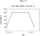
- FIG. 17 is a graph illustrating a relationship between laser beam irradiation output and time in the grooving process by a laser method according to this embodiment.
- FIG. 18 is a view illustrating a groove that is formed in a steel sheet surface of a grain-oriented electrical steel sheet of Example 1.
- FIG. 19 is a view illustrating a longitudinal groove projection line of adjacent grooves of a groove group of a grain-oriented electrical steel sheet in a modification example of this embodiment.
- FIG. 20 is a view illustrating a longitudinal groove projection line of adjacent grooves of a groove group of a grain-oriented electrical steel sheer in a modification example of this embodiment.
- FIG. 21 is a view illustrating a longitudinal groove projection line of adjacent grooves of a groove group of a grain-oriented electrical steel sheet in a modification example of this embodiment.
- FIG. 22 is a graph illustrating a distribution of a total value of groove depths of adjacent grooves of a grain-oriented electrical steel sheet in a modification example of this embodiment.
- FIG. 1 is a plan view of a grain-oriented electrical steel sheet 1 according to this embodiment.
- FIG. 2 is an arrow cross-sectional view taken along line A-A in FIG. 1 .
- FIG. 3 is an arrow cross-sectional view taken along line B-B in FIG. 1 .
- a rolling direction of the grain-oriented electrical steel sheet 1 is defined as X
- a sheet width direction (direction perpendicular to the rolling direction in the same plane) of the grain-oriented electrical steel sheet 1 is defined as Y
- a sheet thickness direction (direction perpendicular to an XY plane) of the grain-oriented electrical steel sheet 1 is defined as Z.
- the grain-oriented electrical steel sheet 1 according to this embodiment includes a groove 3 for magnetic domain refinement in a steel sheet surface 2 a .
- FIG. 1 is a schematic view illustrating a groove 3 when the grain-oriented electrical steel sheet 1 according to this embodiment is seen from the sheet thickness direction Z (hereinafter, may be described as “in a plan view”).
- an extension direction (an arrow L illustrated in FIG. 1 ) of the groove 3 is set as a longitudinal groove direction L.
- a direction (an arrow Q illustrated in FIG. 1 ) that is perpendicular to the longitudinal groove direction L of the groove 3 is set as a groove width direction Q.
- the groove 3 may have an arc shape when being seen from the sheet thickness direction Z (in a case of a plan view of the groove 3 ).
- the groove 3 having a linear shape is exemplified for convenience of explanation.
- the grain-oriented electrical steel sheet 1 includes a steel sheet (base metal) 2 in which a crystal orientation is controlled by a combination of a cold-rolling treatment and an annealing treatment so that a magnetization easy axis of a crystal grain and the rolling direction X match each other, and the groove 3 is provided in a surface (steel sheet surface 2 a ) of the steel sheet 2 .
- the steel sheet 2 contains, as chemical components in terms of mass fraction, Si: 0.8% to 7%, C: greater than 0% and equal to or less than 0.085%, acid-soluble Al: 0% to 0.065%, N: 0% to 0.012%, Mn: 0% to 1%, Cr: 0% to 0.3%, Cu: 0% to 0.4%, P: 0% to 0.5% Sn; 0% to 0.3% Sb: 0% to 0.3%, Ni: 0% to 1%, S: 0% to 0.015% Se: 0% to 0.015%, and the remainder including Fc and unavoidable impurities.
- the chemical components of the steel sheet 2 are chemical components which are preferable after a crystal orientation is integrated to a ⁇ 110 ⁇ ⁇ 001> orientation, that is, after a control to a Goss texture.
- Si and C are basic elements
- acid-soluble Al, N, Mn, Cr, Cu, P, Sn, Sb, Ni, S, and Se are selective elements.
- the selective elements may be contained in correspondence with the purpose thereof. Accordingly, it is not necessary to limit the lower limit, and the lower limit may be 0%.
- the effect of this embodiment docs not deteriorate even when the selective elements are contained as impurities.
- the remainder of the basic elements and the selective elements may be composed of Fe and impurities.
- the impurities represent elements which are unavoidably mixed in due to ore and scrap as a raw material, or a manufacturing environment and the like when industrially manufacturing the steel sheet 2 .
- an electrical steel sheet is typically subjected to purification annealing during secondary recrystal ligation.
- Discharge of an inhibitor forming element to the outside of a system occurs in the purification annealing.
- a decrease in a concentration significantly occurs with respect to N and S, and the concentration becomes 50 ppm or less.
- the concentration becomes 9 ppm or less, or 6 ppm or less. If the purification annealing is sufficiently performed, the concentration reaches to a certain extent (1 ppm or less) at which detection is impossible in typical analysis.
- the chemical component of the sleet sheet 2 may be measured in accordance with a typical steel analysis method.
- the chemical components of the steel sheet 2 may be measured by using inductively coupled plasma-atomic emission spectrometry (ICP-AES).
- ICP-AES inductively coupled plasma-atomic emission spectrometry
- C and S may be measured by using a combustion-infrared ray absorption method
- N may be measured by using inert gas fusion-thermal conductivity method.
- the grain-oriented electrical steel sheet 1 may include an insulating film (not illustrated) on the groove 3 and the steel sheet surface 2 a.
- a glass film (not illustrated) may be provided between the steel sheet surface 2 a and the insulating film.
- the glass film is constituted by a composite oxide such as forsterite (Mg 2 SiO 4 ), spinel (MgAl 2 O 4 ), and cordierite (Mg 2 Al 4 Si 2 O 16 ).
- the glass film is a film that is formed to prevent adhering to the steel sheet 2 in a final annealing process that is one of manufacturing processes of the grain-oriented electrical steel sheet 1 .
- the glass film is not an essential element among constituent elements of the grain-oriented electrical steel sheet 1 .
- the insulating film contains colloidal silica and phosphate, and plays a role of applying electrical insulating properties, a tensile force, corrosion resistance, heat resistance, and the like to the steel sheet 2 .
- the glass film and the insulating film of the grain-oriented electrical steel sheet 1 can be removed by the following method.
- the grain-oriented electrical steel sheet 1 including glass film or the insulating film is immersed in an aqueous sodium hydroxide solution containing 10 mass % of NaOH and 90 mass % of H 2 O at 80° C. for 15 minutes.
- the grain-oriented electrical steel sheet 1 is immersed in an aqueous sulfuric acid solution containing 10 mass % of H 2 SO 4 and 90 mass % of H 2 O al 80° C. for 3 minutes.
- the grain-oriented electrical steel sheet 1 is immersed in an aqueous nitric acid solution containing 10 mass % of HNO 3 and 90 mass % of H 2 O at room temperature for a time period that is slightly shorter than 1 minute, and is washed. Finally, the grain-oriented electrical steel sheet 1 is dried by using a warm wind blower for a time period that is slightly shorter than 1 minute. Furthermore, in a case where the glass film or the insulating film is removed from the grain-oriented electrical steel sheet 1 according to the above-described method, it is confirmed that a shape or roughness of the groove 3 of the steel sheet 2 is approximately the same as a shape or roughness before forming the glass film or the insulating film.
- the groove 3 is formed in such a manner that the groove 3 extends in a direction that intersects the rolling direction X and a depth direction matches the sheet thickness direction Z.
- the grain-oriented electrical steel sheet 1 includes a groove group 30 that is constituted by a plurality of the grooves 3 arranged in the sheet width direction Y.
- the grooves 3 which constitute the groove group 30 , are arranged in such a manner that adjacent groove overlap each other.
- the plurality of grooves 3 which constitute the groove group 30 , are formed as a first groove 31 , a second groove 32 , and an n th groove 3 n in an order close to the reference end 21 a .
- the first groove 31 , the second groove 32 , and the n th groove 3 n are arranged in such a manner that ends of the grooves 3 , which are adjacent to each other on a projection plane perpendicular to the rolling direction X, overlap each other.
- the groove group 30 is arranged to be spaced away from another groove group 30 in the rolling direction X.
- an inclined portion 5 which is inclined so that a depth becomes deeper as it goes from the steel sheet surface 2 a toward the bottom 4 of the groove 3 , is formed at both ends in the longitudinal groove direction L.
- the inclined portion 5 is provided at the both ends in the longitudinal groove direction L, when the grooves 3 are arranged in such a manner that ends of the grooves 3 adjacent to each other overlap each other as described below, it is possible to effectively improve the iron loss.
- the depth of the groove 3 represents a length from the height of the steel sheet surface 2 a to a surface (bottom 4 ) of the groove 3 in the sheet thickness direction Z.
- the average groove depth D may be measured as follows.
- an observation range is set to a part of the groove 3 . It is preferable that the observation range is set to a region excluding an end in the longitudinal groove direction L of the groove 3 (that is, a region in which a shape of the groove bottom is stable).
- the observation range may be an observation region of which a length in the longitudinal groove direction L becomes approximately 30 ⁇ m to 300 ⁇ m at an approximately central portion in the longitudinal groove direction L.
- a height distribution (groove depth distribution) in the observation range is obtained by using a laser microscope and the maximum groove depth is obtained in the observation range.
- the same measurement is performed at least at three or greater regions, and preferably 10 regions while changing the observation range.
- an average value of the maximum groove depth al the respective observation regions is calculated, and the average value is defined as an average groove depth D.
- the average groove depth D of the groove 3 in this embodiment is preferably 5 ⁇ m to 100 ⁇ m, and more preferably greater than 10 ⁇ m and equal to or less than 40 ⁇ m so as to preferably obtain an effect of the magnetic domain refinement.
- the position (height) in the sheet thickness direction Z is measured with respect to a plurality of sites on the steel shed surface 2 a in each of the observation ranges by using a laser microscope, and an average value of the measurement results may be used as the height of the steel sheet surface 2 a .
- a transverse groove cross-section is used when measuring an average groove width W as described later. Accordingly, the steel sheet surface 2 a may be measured from the transverse groove cross-section.
- two sheet surfaces (an observation surface and a rear surface thereof) of the steel sheet sample are approximately parallel to each other.
- the width of the groove 3 represents a length of a groove opening in the transverse groove direction Q in a case where the groove 3 is seen on a cross-section (a groove-width-direction cross-section or a transverse groove cross-section) that is perpendicular to the longitudinal groove direction L.
- the average groove width W may be measured as follows. As is the case with the average groove depth D, an observation range is set to a part of the groove 3 in a case where the groove 3 is seen from the sheet thickness direction Z (in a case of a plan view of the groove 3 ). It is preferable that the observation range is set to a region excluding an end in the longitudinal groove direction L of the groove 3 (that is, a region in which a shape of the groove bottom is stable).
- the observation range may be an observation region of which a length in the longitudinal groove direction L becomes approximately 30 ⁇ m to 300 ⁇ m at an approximately central portion in the longitudinal groove direction L.
- a transverse groove cross-section that is perpendicular to the longitudinal groove direction L is obtained at arbitrary one site in the observation range (for example, a position of the maximum groove depth in the observation region) by using a laser microscope.
- a length of the groove opening is obtained from a contour curve of the steel sheet surface 2 a and the groove 3 on the transverse groove cross-section.
- a band filter cut-off value: ⁇ f, ⁇ c
- a waving curve WWC which constitutes a contour of the groove 3 in the transverse groove cross-section
- a length (groove opening) W n of a line segment which connects two points (a third point 33 and a fourth point 34 ) at which the depth from the steel sheet surface 2 a to the surface of the groove 3 along the sheet thickness direction Z becomes 0.05 ⁇ D with respect to the average groove depth D of the groove 3 , is obtained on the waving curve WWC of the groove 3 at the transverse groove cross-section.
- the same measurement is performed at least at three regions or greater regions and preferably 10 regions while changing the observation range.
- an average value of the groove opening at the respective observation regions is calculated, and the average value is defined as an average groove width W.
- the average groove width W of the groove 3 in this embodiment is 10 ⁇ m to 250 ⁇ m so as to preferably obtain the effect of the magnetic domain refinement.
- the position (height) in the sheet thickness direction Z is measured with respect to a plurality of sites on the steel sheet surface 2 a on a waving curve in each transverse groove cross-section, and an average value of the measurement results may be used as the height of the steel sheet surface 2 a.
- the first angle ⁇ of the groove 3 represents an angle made by the steel sheet surface 2 a and the end of the groove 3 .
- the first angle ⁇ may be measured as follows. In a case where the groove 3 is seen from the sheet thickness direction Z (in a case of a plan view of the groove 3 ), an observation range is set to a part of the groove 3 which includes an end in the longitudinal groove direction L. In a plan view of the groove 3 from the sheet thickness direction Z, a plurality of (n) virtual lines L 1 to L n are virtually set in the observation range along the longitudinal groove direction L (refer to FIG. 6 ).
- the observation range is set to a region including the end of the groove 3 (that is, a region ranging from a starting point of the groove 3 in the longitudinal groove direction L to a region in which a shape of the groove bottom is stable).
- a measurement cross-section curve MCL 1 which constitutes a contour of the end of the groove 3 in the longitudinal groove direction L, is obtained in a shape conforming to the virtual line L 1 .
- a cross-section curve After obtaining a cross-section curve by applying a low-pass filter (cut-off value: ⁇ s) to the measurement cross-section curve MCL 1 obtained with respect to the virtual line L 1 , when a band filter (cut-off value: ⁇ f, ⁇ c) is applied to the cross-section curve to remove long wavelength components and short wavelength components from the cross-section curve, as illustrated in FIG. 5 , a waving curve LWC 1 , which constitutes a contour of the end of the groove 3 in the longitudinal groove direction L, is obtained in a shape conforming to the virtual line L 1 .
- distances (depths d 1 to dn: unit is ⁇ m) in the sheet thickness direction Z between the steel sheet surface 2 a and the contour (that is, the waving curve LWC 1 ) of the groove 3 are obtained at a plurality of (n) positions along the virtual line L 1 .
- an average value (groove depth D 1 ) of the depths d 1 to dn is obtained.
- Groove depths D 2 to Dn of the groove end are also obtained with respect to other virtual lines L 2 to Ln according to the same measurement method.
- the position (height) in the sheet thickness direction Z may be measured with respect to a plurality of sites on the steel sheet surface 2 a in the measurement range by using the laser microscope, and an average value of the measurement results may be used as the height of the steel sheet surface 2 a.
- a virtual line which conforms to the longitudinal groove direction L and satisfies a condition in which the average depth of the groove becomes the maximum, is selected as a groove reference line BL.
- the groove reference line BL is defined as the groove reference line BL.
- a straight line which connects a first point 51 at which the depth from the steel sheet surface 2 a in the sheet thickness direction Z becomes 0.05 ⁇ D, and a second point 52 at which the depth from the steel sheet surface 2 a in the sheet thickness direction Z becomes 0.50 ⁇ D, is set as a groove end straight line 3 E.
- the first angle ⁇ of the groove 3 is defined as an inclination angle of the groove end straight line 3 E with respect to the steel sheet surface 2 a.
- a contour, which is projected onto the projection plane, in the longitudinal groove direction L is defined as a longitudinal groove projection line LWP.
- the longitudinal groove projection line LWP may be measured as follows. In a plan view of the groove 3 from the sheet thickness direction Z, the observation range is set to a region including the entirety of the groove 3 or a region including an end of the groove 3 (that is, region ranging from a starting point of the groove 3 in the longitudinal groove direction L to a region in which a shape of the groove bottom is stable).
- a plurality of virtual lines along the longitudinal groove direction L are virtually set in the observation range. It is assumed that virtual lines L 1 to L n can be set at an arbitrary height in the sheet thickness direction Z. In addition, a virtual line at which the groove depth becomes the maximum is selected by the same method as the method described with regard to the groove reference line BL. A curve, which is obtained when projecting a groove depth distribution along the selected virtual line onto the projection plane as the entirely of a contour (waving curve) of the groove 3 in the longitudinal groove direction L, is set as the longitudinal groove projection line LWP.
- the observation range is set to a region including the entirety of two adjacent grooves, or a region including an end at which two adjacent grooves overlap each other (that is, a region including a region in which a groove bottom shape of one groove is stable, a region in which groove ends of two adjacent grooves overlap each other, and a region in which a groove bottom shape of the other groove is stable).
- Two groove ends of grooves, which constitute the groove group 30 , in the longitudinal groove direction L are set as a first groove end and a second groove end in the order close to the reference end 21 a .
- FIG. 8 schematically illustrates a first groove end 31 a and a second groove end 31 b of a first longitudinal groove projection line LWP 1 of the first groove 31 , and a first groove end 32 a and a second groove end 32 b of a second longitudinal groove projection line LWP 2 of the second groove 32 .
- FIG. 8 only two grooves 31 and 32 adjacent to each other in the sheet width direction Y are extracted among the plurality of grooves 3 of the grain-oriented electrical steel sheet 1 according to this embodiment, and are described for explanation of a positional relationship between adjacent grooves in the sheet width direction Y.
- the second groove end 31 b of the first groove 31 and the first groove end 32 a of the second groove 32 which are adjacent to each other in the sheet width direction Y, are arranged to overlap each other in the sheet width direction Y.
- FIG. 8 exemplifies a disposition in which ends of the first groove 31 and the second groove 32 , which are adjacent to each other in the sheet width direction Y, do not overlap each other when seen from the sheet thickness direction Z.
- ends of the first groove 31 and the second groove 32 may overlap each other when seen in the sheet thickness direction Z.
- the first groove 31 and the second groove 32 may be regarded as one groove.
- Adjacent grooves overlap each other in the sheet width direction Y in such a manner that a position of the first groove end 32 a of the second groove 32 in the second longitudinal groove projection line LWP 2 in the sheet width direction Y is located on a further reference end 21 a side in comparison to a position of the second groove end 31 b of the first groove 31 in the first longitudinal groove projection line LWP 1 in the sheet width direction Y.
- a region between the second groove end 31 b of the first groove 31 and the first groove end 32 a of the second groove 32 is a region R in which the first groove 31 and the second groove 32 overlap each other in the sheet width direction Y.
- a plurality of grooves are formed in the sheet width direction Y, and the grooves 31 and 32 adjacent to each other overlap each other. Accordingly, even when using the grooves 31 , 32 , . . . , 3 n having the inclined portion 5 , it is possible to suppress the iron loss to a low value.
- a spaced distance (distance F 1 illustrated in FIG. 1 ) between the first groove 31 and the second groove 32 , which are adjacent to each other in the sheet width direction Y, in the rolling direction X is set to be smaller than a spaced distance (distance F 2 illustrated in FIG. 1 ) between the groove groups 30 , which are adjacent to each other in the rolling direction X, in the rolling direction X.
- a position (a point on the first longitudinal groove projection line LWP 1 ) at which a depth in the sheet thickness direction Z from the steel sheet surface 2 a to a contour in the longitudinal groove direction L becomes 0.05 ⁇ D A is referred to as a 0.05 D A position (second point) of the second groove end 31 b of the first groove 31 .
- a position (a point on the second longitudinal groove projection line LWP 2 ) at which a depth in the sheet thickness direction Z from the steel sheet surface 2 a to a contour in the longitudinal groove direction L becomes 0.05 ⁇ D A is referred to as a 0.05 D A position (first point) of the first groove end 32 a of the second groove 32 .
- the first groove 31 and live second groove 32 are arranged in such a manner that a distance between the 0.05 D A position (the first point on the second longitudinal groove projection line LWP 2 ) of the first groove end 32 a of the second groove 32 and the reference end 21 a of the steel sheet 2 is shorter than a distance between the 0.05 D A position (the second point on the first longitudinal groove projection line LWP 1 ) of the second groove end 31 b of the first groove 31 and the reference end 21 a of the steel sheet 2 .
- An arbitrary point on the first longitudinal groove projection line LWP 1 which is included in the overlapping region R between the first groove end 32 a of the second groove 32 and the second groove end 31 b of the first groove 31 , is set as P 1 , and among points on the second longitudinal groove projection line LWP 2 that is included in the overlapping region R, a point, at which a distance from the reference end 21 a is the same as a distance between the point P 1 and the reference end 21 a (that is, a point at which a position in the sheet width direction Y is the same as in the point P 1 ), is set as P 2 .
- a total depth of a depth of the first groove 31 from the steel sheet surface 2 a to the point P 1 on the first longitudinal groove projection line LWP 1 in the sheet thickness direction Z, and a depth of the second groove 32 from the steel sheet surface 2 a to the point P 2 on the second longitudinal groove projection line LWP 2 in the sheet thickness direction Z is 0.5 ⁇ D A or greater. That is, even when the points P 1 and P 2 exist at any position in the overlapping region R, the condition of “the total depth is 0.5 ⁇ D A or greater” is satisfied. As illustrated in FIG. 8 and FIG.
- the depth of the first groove 31 and the depth of me second groove 32 at the points P (P 1 , P 2 ), at which distances from the reference end 21 a are the same as each other, are added to each other.
- the grooves 3 are arranged in such a manner that a total value of the depth of the first groove 31 and the second groove 32 at the points P becomes 0.5 ⁇ D A or greater with respect to the average groove group depth D A of the plurality of grooves which are formed in the sheet width direction Y.
- FIG. 8 longitudinal groove projection lines, which are obtained by projecting contours in the longitudinal groove direction L onto the projection plane, are shown on the coordinates.
- FIG. 9 is a graph illustrating a relationship between a position of a region from the first groove end 31 a of the first groove 31 and the second groove end 32 b of the second groove 32 in the sheet width direction Y, and the total groove depth.
- the longitudinal groove projection lines are shown as a simplified straight line.
- the first groove 31 and the second groove 32 overlap each other from groove ends to the region of the bottom 4 described in the embodiment.
- the maximum value of the total groove depth of the first groove 31 and the second groove 32 becomes approximately two times the average groove group depth D A in the sheet width direction Y, and the minimum value of the total groove depth becomes approximately the same as the average groove group depth D A in the sheet width direction Y.
- FIG. 10 and FIG. 11 An example, in which the width of the overlapping region R between the first groove 31 and the second groove 32 which are adjacent to each other is different from the width in the example illustrated in FIG. 8 , is illustrated in FIG. 10 and FIG. 11 .
- regions of inclined portions 5 of the first groove 31 and the second groove 32 overlap each other. That is, overlapping is made in such a manner that the first longitudinal groove projection line LWP 1 and the second longitudinal groove projection line LWP 2 intersect each other at positions of the inclined portions 5 of the first groove 31 and the second groove 32 .
- the minimum value of the total groove depth of the first groove 31 and the second groove 32 at points P (P 1 , P 2 ) at which distances from the reference end 21 a are the same as each other becomes smaller than the average groove group depth D A in the sheet width direction Y.
- the minimum value of the total depth in the overlapping region R and the iron loss in the grain-oriented electrical steel sheet including the groove group 30 have a correlation. Furthermore, when the first groove 31 and the second groove 32 overlap each other to satisfy the above-described condition, an inclination angle (first angle ⁇ ) in the groove ends of the grooves 31 and 32 does not have an effect on iron loss characteristics.
- the upper limit of the total depth of the depth of the first groove 31 and the depth of the second groove 32 at the points P (P 1 , P 2 ) in the sheet width direction Y is not limited, but the upper limit may be two or less times the average groove group depth D A when considering a decrease in a magnetic flux density.
- the total depth of the depth of the first groove 31 and the depth of the second groove 32 at the points P (P 1 , P 2 ) in the sheet width direction Y is set to two or less times the average groove group depth D A , a variation amount of the groove depth in the sheet width direction Y is suppressed to be small. Accordingly, it is possible to stably improve the iron loss in a more effective manner.
- an end of the groove 3 which is provided in the grain-oriented electrical steel sheet 1 according to this embodiment, is inclined so that in groove ends 31 a and 31 b of the groove 3 in the longitudinal groove direction L, a relationship between an angle (first angle ⁇ ) made by the groove end straight line 3 E and the steel sheet surface 2 a , and an aspect ratio A obtained by dividing the average groove depth D by the average groove width W satisfy the following Expression (1). ⁇ 21 ⁇ A+ 77 (1)
- A an aspect ratio
- the iron loss affected by the groove depth is improved.
- the average groove width W is smaller, a deterioration amount of a magnetic flux density that deteriorates due to removal of a steel portion is suppressed to be small. Accordingly, the iron loss can be improved. That is, as the aspect ratio A is greater, it is possible to preferably control the magnetic characteristics. On the other hand, as the aspect ratio A is greater, a coating solution is less likely to intrude into the groove.
- the rust resistance deteriorates.
- the rust resistance deteriorates at the groove end of the groove 3 .
- the first angle ⁇ of the groove 3 deviates from the range of Expression (1)
- the inclination angle of the groove end of the groove 3 with respect to the aspect ratio becomes great. Therefore, it is difficult to coat the groove 3 with the glass film or the insulating film al the groove end of the groove 3 . As a result, rust is likely to occur at the groove end of the groove 3 .
- the average groove depth D is deeper, it is necessary make the inclination angle (first angle ⁇ ) at the groove end be smaller so as to suppress occurrence of rust.
- the average groove width W is narrower, it is necessary to make the inclination angle (first angle ⁇ ) at the groove end be smaller so as to suppress occurrence of rust.
- Expression (1) when a relationship of the average groove depth D, the average groove width W, and the first angle ⁇ satisfies Expression (1), it is possible to attain the effect of making a magnetic characteristic improvement and rust resistance be compatible with each other in the groove 3 .
- the average groove depth D of the groove 3 becomes 30% or greater with respect to the thickness of the grain-oriented electrical steel sheet in the sheet thickness direction Z, the amount of the grain-oriented electrical steel sheet that is a magnetic material, that is, the amount of the steel sheet decreases. Therefore, there is a concern that the magnetic flux density may decrease.
- the upper limit of the average depth D of the groove 3 may be 100 ⁇ m when considering that a typical thickness of the grain-oriented electrical steel sheet for a wound transformer is 0.35 mm or less.
- the groove 3 may be formed in one surface of the grain-oriented electrical steel sheet, or may be formed in both surfaces thereof.
- the first angle ⁇ of the groove end of the groove 3 to satisfy the following Expression (3) with respect to the average groove depth D and the average groove width W from the viewpoint of improving the rust resistance. ⁇ 0.12 ⁇ W ⁇ 0.45 ⁇ D+ 57.39 (3)
- the average groove width W is greater than 30 ⁇ m and equal to or less than 100 ⁇ m, it becomes apparent that it is more preferable for the first angle ⁇ of the groove end of the groove 3 to satisfy the following Expression (4) with respect to the average groove depth D and the average groove width W from the viewpoint of improving the rust resistance. ⁇ 0.37 ⁇ D+ 0.12 ⁇ W+ 55.39 (4)
- the magnetic characteristics and the rust resistance can be compatible with each other.
- a grain-oriented electrical steel sheet with high quality is obtained.
- ends of the groove reach both end surfaces of the grain-oriented electrical steel sheet in the sheet width direction Y, the inclined portion is not formed at the ends of the groove. Accordingly, it is needless to say that the above-described conditions are not applied.
- an average grain size of a crystal grain (secondary recrystallized grain) that is in contact with the groove 3 is 5 ⁇ m or greater.
- the upper limit of the grain size of the crystal grain that is in contact with the groove 3 is not particularly limited, but the upper limit may be set to 100 ⁇ 10 3 ⁇ m or less. In a case where a melted and resolidified region, which is derived from formation of the groove 3 , exists at the periphery of the groove 3 , the grain size of the crystal grain that is in contact with the groove 3 becomes fine.
- the grain size of the crystal grain represents an equivalent circle diameter.
- the grain size of the crystal grain may be obtained in accordance with a typical crystal grain size measurement method such as ASTM E112, or may be obtained in accordance with an electron back scattering diffraction pattern (EBSD) method.
- the crystal grain that is in contact with the groove 3 may be observed on the transverse groove cross-section or a cross-section that is perpendicular to the sheet thickness direction Z.
- the groove that does not include the melted and resolidified region may be obtained in accordance with a manufacturing method to be described later.
- an oxide layer containing silica as a main component reacts with the annealing separating agent that contain magnesia as a main component, and the glass film (not illustrated) including a composite oxide such as forsterite (Mg 2 SiO 4 ) is formed on a surface of the steel sheet 2 .
- the final annealing treatment is performed in a state in which the steel sheet 2 is coiled in a coil shape.
- the glass film is formed on the surface of the steel sheet 2 during the final annealing treatment. Accordingly, it is possible to prevent adhering to the steel sheet 2 that is coiled in a coil shape.
- an insulating coating solution containing colloidal silica and a phosphate is applied to the steel sheet surface 2 a from an upper side of the glass film. Then, when a heat treatment is performed under a predetermined temperature condition (for example, 840° C. to 920° C.), the insulating film is formed on the surface of the glass film.
- a predetermined temperature condition for example, 840° C. to 920° C.
- a fiber laser can be used as the laser light source.
- a high output laser such as a YAG laser, a semiconductor laser, and a CO 2 laser, which are typically used for industry, may be used as the laser light source.
- a pulse laser or a continuous wave laser may be used as the laser light source as long as the groove 3 can be stably formed.
- a laser output is set to 200 W to 2000 W
- a light-condensing spot diameter of the laser light YL in the rolling direction X (that is, a diameter including 86% of the laser output, hereinafter, referred to as 86% diameter) is set to 10 ⁇ m to 1000 ⁇ m
- a light-condensing spot diameter (86% diameter) in the sheet width direction Y of the laser light YL is set to 10 ⁇ m to 4000 ⁇ m
- a laser scanning speed is set to 1 m/s to 100 m/s
- a laser scanning pitch (interval PL) is set to 4 mm to 10 mm.
- Scanning with a laser beam over the whole width of the grain-oriented electrical steel sheet may be performed by one scanning apparatus as illustrated in FIG. 13 , or may be performed by a plurality of the scanning apparatuses as illustrated in FIG. 16 .
- one light source laser beams emitted from the light source and the resultant divided laser beams are used as the laser beam.
- the plurality of laser irradiation devices 10 are disposed along the rolling direction X at a predetermined interval.
- positions of the respective laser irradiation devices 10 in the sheet width direction Y are set so that laser scanning lines of the respective laser irradiation devices 10 do not overlap each other.
- the steel sheet 2 of the grain-oriented electrical steel sheet 1 manufactured as described above contains, as chemical components in terms of mass fraction. Si: 0.8% to 7%, C: greater than 0% and equal to or less than 0.085%, acid-soluble Al: 0% to 0.065%, N: 0% to 0.012%, Mn: 0% to 1%, Cr: 0% to 0.3%, Cu: 0% to 0.4%, P: 0% to 0.5%, Sn: 0% to 0.3%, Sb: 0% to 0.3%, Ni: 0% to 1%, S: 0% to 0.015% Se: 0% to 0.015%, and the remainder including Fe and unavoidable impurities.
- the embodiment exemplifies a case of employing a manufacturing process in which the groove 3 is formed in the steel sheet surface 2 a after the insulating film is formed on the steel sheet surface 2 a with laser irradiation.
- the groove 3 immediately after laser irradiation is exposed to the outside. Accordingly, it is necessary to form an insulating film again on the steel sheet 2 after forming the groove 3 .
- the glass film or the insulating film may be formed after the groove 3 is formed in the steel sheet 2 .
- the shape or the roughness of the groove 3 after removing the glass film or the insulating film is approximately the same as those before forming the glass film or the insulating film.
- This embodiment exemplifies an example in which the shape of the groove 3 (shape of a boundary portion between the groove 3 and the steel sheet surface 2 a ) in a plan view is an elongated ellipse.
- the shape of the groove 3 in the grain-oriented electrical steel sheet 1 is not limited thereto.
- the groove 3 may have an arbitrary shape as long as the inclined portion is provided to the ends in the longitudinal groove direction L and the relationship of Expression (1) is satisfied.
- the overlapping region is provided between a plurality of grooves in the sheet width direction Y. Accordingly, even when using the grooves 31 , 32 . . . , 3 n having an inclined surface, it is possible to suppress the iron loss to a low value.
- the grain-oriented electrical steel sheet 1 according to this embodiment may be defined as follows from another viewpoint.
- an average value of depths of the first longitudinal groove projection line LWP 1 which is a contour of the first groove 31 that is projected onto the projection plane, from the steel sheet surface 2 a in the sheet thickness direction Z is set as a first average groove depth D I in a unit of ⁇ m.
- An average value of depths of the second longitudinal groove projection line LWP 2 which is a contour of the second groove 32 that is projected onto the projection plane, from the steel sheet surface 2 a in the sheet thickness direction Z is set as a second average groove depth D II in a unit of ⁇ m.
- the overlapping region R of the grain-oriented electrical steel sheet 1 according to this modification example may be defined as a distance between a point (third point), at which a depth from the steel sheet surface 2 a in the sheet thickness direction Z becomes 0.05 ⁇ D II , at the first groove end 32 a of the second longitudinal groove projection line LWP 2 , and a point (fourth point), at which a depth from the steel sheet surface 2 a in the sheet thickness direction Z becomes 0.05 ⁇ D I , at the second groove end 31 b of the first longitudinal groove projection line LWP 1 on the projection plane.
- the grain-oriented electrical steel sheet 1 when a plurality of the grooves 3 are formed in such a manner that the plurality of grooves 3 overlap each other in the sheet width direction Y, even when the grooves 3 include the inclined portion 5 , it is possible to suppress the iron loss to a low value. That is, even in the groove 3 in which an inclined portion 5 is formed on both ends in the longitudinal groove direction L to improve the rust resistance, if a plurality of the grooves 3 are arranged in the sheet width direction Y, and both ends of adjacent grooves 3 are arranged to overlap each other in the sheet width direction Y, it is possible to improve the iron loss similar to a case where one groove 3 having a uniform depth is formed in the sheet width direction Y.
- a distance La between the third point on the second longitudinal groove projection line LWP 2 and the reference end 21 a is shorter than a distance Lb between the fourth point on the first longitudinal groove projection line LWP 1 and the reference end 21 a .
- a reference line that is parallel to the sheet thickness direction Z in the overlapping region R is set, with regard to a shape of any reference line in the overlapping region R, a total depth of a depth of the first longitudinal groove projection line LWP 1 from the steel sheet surface 2 a in the sheet thickness direction Z and a depth of the second longitudinal groove projection line LWP 2 from the steel sheet surface 2 a in the sheet thickness direction Z is 0.25 ⁇ (D I +D II ) or greater in a unit of ⁇ m.
- FIG. 19 to FIG. 21 illustrate examples which are different in the width of the overlapping region R between the first groove 31 and the second groove 32 .
- FIG. 19 illustrates an example in which respective inclined portions 5 of the first groove 31 and the second groove 32 overlap each other, and a part of the bottom 4 a of the first groove 31 and a part of the bottom 4 b of the second groove 32 overlap each other.
- FIG. 20 illustrates an example in which the majorities of the inclined portions 5 of the first groove 31 and the second groove 32 overlap each other. That is, in the example illustrated in FIG. 20 , the first longitudinal groove projection line LWP 1 and the second longitudinal groove projection line LWP 2 overlap each other to intersect at the inclined portions 5 . Similar to FIG. 20 , FIG.
- FIG. 21 illustrates an example in which grooves overlap each other in such a manner that the first longitudinal groove projection line LWP 1 and the second longitudinal groove projection line LWP 2 intersect each other at the inclined portions 5 , and the distance Lc of the first longitudinal groove projection line LWP 1 becomes shorter than the distance La of the second longitudinal groove projection line LWP 2 .
- FIG. 22 illustrates a profile of a total depth of the first longitudinal groove projection line LWP 1 and the second longitudinal groove projection line LWP 2 which are illustrated in FIG. 21 . As illustrated in FIG. 22 , in the overlapping region R of the example illustrated in FIG.
- the minimum value of the total depth in the overlapping region R and iron loss characteristics of the grain-oriented electrical steel sheet 1 including the groove group 30 have a correlation. Furthermore, when the first groove 31 and the second groove 32 overlap each other to satisfy the above-described condition, the inclination angle (first angle ⁇ ) at the groove end does not have an effect on the iron loss characteristics.
- Decarburization annealing was performed with respect to the cold-rolled material under a condition of a temperature of 800° C. for two minutes (decarburization annealing process S 05 ).
- annealing separating agent applying process S 06 An annealing separating agent containing magnesia as a main component was applied to both surfaces of the cold-rolled material after the decarburization annealing (annealing separating agent applying process S 06 ).
- the cold-rolled material to which the annealing separating agent was applied was put in a furnace in a state of being coiled in a coil shape, and the final annealing process S 07 was performed at a temperature of 1200° C. for 20 hours to prepare steel sheet base metal on which the glass film was formed on a surface thereof.
- an insulating material containing aluminum phosphate as a main component was applied onto the glass film, and baking was performed at a temperature of 850° C. for one minute to form the insulating film (insulating film forming process S 08 ).
- a plurality of the grooves 31 , 32 , . . . , 3 n were disposed in such a manner that the inclination angle ⁇ 4 with respect to the sheet width direction Y was set to 15°, a spaced distance G between a line connecting the groove end 31 a and the groove end 31 b of the groove 31 , and a line connecting the groove end 32 a and the groove end 32 b of the groove 32 positioned in the vicinity of the groove 31 was set to 1 mm, overlapping was made by 3 mm, a length of a line segment m connecting the second groove end 32 b of the first groove 31 and the first groove end 32 a of the second groove 32 was set to approximately 3.4 mm, and an angle ⁇ 5 of the line segment m with respect to the sheet width direction Y was set to approximately 150° (refer to FIG.
- the first groove end 32 a of the second groove 32 is located on a further reference end 21 a side in comparison to the second groove end 31 b of the first groove 31 . Accordingly, the overlapping region R is provided.
- the average groove group depth D A of the average groove group depth D A of Example 1 was 20 ⁇ m, and the minimum value of the total groove depth in the overlapping region R was 20 ⁇ m and was 0.5 ⁇ D A or greater.
- a plurality of grooves which were arranged in the sheet width direction Y were continuously formed in a state of being spaced away from each other with a pitch of 3 mm in the rolling direction X.
- Example 2 to Example 4 which are different from Example 1 in the minimum value of the total groove depth, were prepared. That is, Example 2 is an example in which the minimum value of the total groove depth in the overlapping region R is 10 ⁇ m.
- Example 3 is an example in which the minimum value is 15 ⁇ m, and
- Example 4 is an example in which the minimum value is 25 ⁇ m.
- the arrangement was made in such a manner that in the longitudinal groove projection line, the second groove end 31 b of the first groove 31 was located on a further reference end 21 a side in comparison to the first groove end 32 a of the second groove 32 , and an inclination angle of a line segment connecting the first groove end 32 a of the second groove 32 and the second groove end 31 b of the first groove 31 became perpendicular to the longitudinal groove direction L and became 75° with respect to the sheet width direction Y. That is, the minimum value of the total groove depth was 0 ⁇ m.
- Comparative Example 2 a grain-oriented electrical steel sheet, in which the grooves are arranged to overlap each other similar to Example 1, but the minimum value of the total groove depth in the overlapping region R is less than 0.5 ⁇ D A , was prepared. That is, a grain-oriented electrical steel sheet, in which the average groove group depth D A is 20 ⁇ m, and the minimum value of the total groove depth in the overlapping region R is 5 ⁇ m, was prepared as Comparative Example 2.
- test pieces which include one or more grooves and have a dimension of 600 mm per one side, were prepared from the grain-oriented electrical steel sheets of Examples 1 to 4, and Comparative Examples 1 and 2.
- Contours of the grooves in Examples 1 and Comparative Examples 1 and 2 were specified on the basis of the contour specifying method as described above.
- a two-dimensional height distribution on ten straight lines L 1 to L 10 in the longitudinal groove direction L was measured with respect to the grooves in the examples and the comparative examples by using a non-contact laser meter (VK-9700, manufactured by Keyence Corporation).
- Ten patterns of contours of the grooves on the longitudinal groove cross-section were obtained on the basis of the measurement results.
- the average groove depth D was calculated from each of the ten patterns of contours of the longitudinal groove cross-section, and a contour of the longitudinal groove cross-section, in which the average groove depth D was the deepest, was extracted as a representative pattern.
- the average groove depth D of the representative pattern is illustrated in a column of the groove depth D in Table 1.
- the average groove group depth D A , and the total groove depth of respective points in the overlapping region R were measured. From the result, the average groove group depth D A of Example 1 was 20 ⁇ m, the minimum value of the total groove depth in the overlapping region R was 20 ⁇ m, and the above-described values were greater than 0.5 ⁇ D A . It was clear that the minimum value of the total groove depth of the overlapping region R and the iron loss have a correlation, and in Example 1, when forming the overlapping region R so that the minimum value of the total depth becomes 10 ⁇ m or greater, it is possible to suppress the iron loss to 0.75 W/kg or less.
- Example 1 in which the first angle ⁇ of the groove 3 is 30° or 45° and Example 1, when adjacent grooves 3 , which constitute the groove group 30 , overlap each other, and the minimum value of the total depth is 0.5 ⁇ D A or greater, in a case where the first angle ⁇ of the groove 3 is 30°, 45°, and 60°, the iron loss hardly varied.
- the iron loss W 17/50 (W/kg) when being subjected to AC excitation under conditions of the maximum magnetic flux density of 1.7 T and a frequency of 50 Hz was measured, and an average value thereof was calculated.
- Example 2 and Example 3 The iron loss of steel sheets (steel sheets after the insulating film forming process S 08 ) before performing grooving in Examples 1 to 4, and Comparative Example 1 and 2 was measured, and the iron loss was set as a reference iron loss to obtain an improvement rate of the iron loss with respect to the reference iron loss. From the result, with regard to the improvement rate of the iron loss, a satisfactory result was obtained in Example 2 and Example 3. In addition, in Example 1 and Example 4, the improvement rate of the iron loss was as very high as 20%. In Comparative Example 1 and Comparative Example 2, the improvement rate of the iron loss improvement rate was lower in comparison to the grain-oriented electrical steel sheets of Examples 1 to 4.
- Example 2 TABLE I Minimum value of total Improvement Average groove groove depth in rate of group depth D A overlapping region R iron loss (unit: ⁇ m) (unit: ⁇ m) (unit: %) Example 1 20 20 20 Example 2 20 10 16 Example 3 20 15 18 Example 4 20 25 20 Comparative 20 0 10 Example 1 Comparative 20 5 12 Example 2
- Grain-oriented electrical steel sheets were prepared as follows.
- a groove in which the average groove depth D, the average groove width W in the longitudinal groove direction L, and the first angle ⁇ were set as illustrated in Table 1, was formed in the steel sheet surface 2 a by using the laser method under conditions in which the laser scanning pitch (interval PL) was set to 3 mm, the beam diameter was set to 0.1 mm in the rolling direction X and 0.3 mm in the scanning direction, and the scanning speed was set to 30 mm/s.
- a grain-oriented electrical steel sheet was prepared as follows.
- a groove, in which the average groove depth D, the average groove width W in the longitudinal groove direction L, and the first angle ⁇ were set as illustrated in Table 2, was formed in the grain-oriented electrical steel sheet.
- a contour on a cross-section in the transverse groove direction Q a two-dimensional height distribution of a groove at twenty straight lines in the transverse groove direction Q was measured by using the same non-contact laser meter. Twenty patterns of contours of the transverse groove cross-section of the groove were obtained on the basis of the measurement results. In the obtained twenty patterns of contours of the transverse groove cross-section, a depth from the steel sheet surface 2 a to the surface (contour) of the groove was measured to calculate an average transverse groove depth D S . In the transverse groove cross-sectional shape, two points having an average transverse groove depth of D S ⁇ 0.05, were extracted, and a distance between the two points was measured as the groove width W. An average value of the groove width W obtained from the twenty patterns was calculated as an average groove width. The average groove width (unit: ⁇ m) of the grain-oriented electrical steel sheets obtained in Examples 5 to 18 and Comparative Examples 3 to 5 is illustrated in Table 2.
- Examples 5 and 6 are examples which satisfy only relationships of Expression (1) and Expression (2) described in the embodiment.
- Examples 12 to 18 are examples which satisfy only a relationship of Expression (1) described in the embodiment.
- Examples 8 and 9 are examples which satisfy relationships of Expression (1) to Expression (4) described in the embodiment.
- Example 7 is an example that satisfies relationships of Expression (1), Expression (2), and Expression (4) described in the embodiment.
- Example 10 is an example that satisfies a relationship of Expression (1), Expression (2), and Expression (3) described in the embodiment.
- Comparative Examples 3 to 5 grain-oriented electrical steel sheets, which do not satisfy Expression (1), were prepared.
- the weight of the test piece increases. Accordingly, as the weight increase amount was smaller, the rust resistance was determined as good. Specifically, the rust resistance of the test piece in which the weight increase amount was 1.0 mg/m 2 or less was evaluated as “very good”, the rust resistance of the test piece in which the weight increase amount was 5.0 mg/m 2 or less was evaluated as “good”, and the rust resistance of the test piece in which the weight increase amount was greater than 10.0 mg/m 2 was evaluated as “poor”. As illustrated in Table 1, from a result of the verification of the rust resistance of the grain-oriented electrical steel sheets of Examples 5 to 18, when a groove satisfying at least Expression (1) is formed, it was confirmed that the rust resistance of the grain-oriented electrical steel sheets is improved.
- an iron loss of a grain-oriented electrical steel sheet, in which a plurality of grooves are formed in a surface of a base metal, is improved, and rust resistance can be improved. Accordingly, the invention has sufficient industrial applicability.
Landscapes
- Chemical & Material Sciences (AREA)
- Engineering & Computer Science (AREA)
- Physics & Mathematics (AREA)
- Materials Engineering (AREA)
- Metallurgy (AREA)
- Organic Chemistry (AREA)
- Mechanical Engineering (AREA)
- Optics & Photonics (AREA)
- Crystallography & Structural Chemistry (AREA)
- Thermal Sciences (AREA)
- Manufacturing & Machinery (AREA)
- Electromagnetism (AREA)
- Power Engineering (AREA)
- Dispersion Chemistry (AREA)
- Electrochemistry (AREA)
- Chemical Kinetics & Catalysis (AREA)
- Plasma & Fusion (AREA)
- Manufacturing Of Steel Electrode Plates (AREA)
- Soft Magnetic Materials (AREA)
Applications Claiming Priority (3)
| Application Number | Priority Date | Filing Date | Title |
|---|---|---|---|
| JP2015086302 | 2015-04-20 | ||
| JP2015-086302 | 2015-04-20 | ||
| PCT/JP2016/062375 WO2016171129A1 (ja) | 2015-04-20 | 2016-04-19 | 方向性電磁鋼板 |
Publications (2)
| Publication Number | Publication Date |
|---|---|
| US20180036838A1 US20180036838A1 (en) | 2018-02-08 |
| US10906134B2 true US10906134B2 (en) | 2021-02-02 |
Family
ID=57144101
Family Applications (1)
| Application Number | Title | Priority Date | Filing Date |
|---|---|---|---|
| US15/554,659 Active 2037-10-05 US10906134B2 (en) | 2015-04-20 | 2016-04-19 | Grain-oriented electrical steel sheet |
Country Status (9)
| Country | Link |
|---|---|
| US (1) | US10906134B2 (zh) |
| EP (1) | EP3287532B1 (zh) |
| JP (1) | JP6575592B2 (zh) |
| KR (1) | KR102008600B1 (zh) |
| CN (1) | CN107406903B (zh) |
| BR (1) | BR112017019141B1 (zh) |
| PL (1) | PL3287532T3 (zh) |
| RU (1) | RU2678351C1 (zh) |
| WO (1) | WO2016171129A1 (zh) |
Families Citing this family (16)
| Publication number | Priority date | Publication date | Assignee | Title |
|---|---|---|---|---|
| EP3330388B1 (en) * | 2015-07-28 | 2021-09-01 | JFE Steel Corporation | Linear groove formation method and linear groove formation device |
| JP7238405B2 (ja) * | 2016-12-06 | 2023-03-14 | 日本電気硝子株式会社 | 帯状ガラスフィルムの品質検査方法 |
| KR20180112354A (ko) * | 2017-04-03 | 2018-10-12 | 삼성전기주식회사 | 자성 시트 및 이를 포함하는 무선 전력 충전 장치 |
| US11964894B2 (en) * | 2018-01-31 | 2024-04-23 | Nippon Electric Glass Co., Ltd. | Glass roll, glass roll manufacturing method, and quality evaluation method |
| JP7027923B2 (ja) * | 2018-02-05 | 2022-03-02 | 日本製鉄株式会社 | 方向性電磁鋼板、巻鉄芯、方向性電磁鋼板の製造方法、及び、巻鉄芯の製造方法 |
| PL3751014T3 (pl) * | 2018-02-08 | 2023-12-27 | Nippon Steel Corporation | Blacha cienka ze stali elektrotechnicznej o ziarnach zorientowanych |
| US11697856B2 (en) * | 2018-02-09 | 2023-07-11 | Nippon Steel Corporation | Grain-oriented electrical steel sheet and manufacturing method thereof |
| JP7031364B2 (ja) * | 2018-02-26 | 2022-03-08 | 日本製鉄株式会社 | 方向性電磁鋼板の製造方法 |
| PL3760746T3 (pl) * | 2018-02-26 | 2024-05-20 | Nippon Steel Corporation | Blacha cienka ze stali elektrotechnicznej o ziarnach zorientowanych |
| CN110323044B (zh) * | 2018-03-30 | 2021-02-19 | 宝山钢铁股份有限公司 | 一种耐热磁畴细化型取向硅钢及其制造方法 |
| JP7010321B2 (ja) * | 2019-03-19 | 2022-02-10 | Jfeスチール株式会社 | 方向性電磁鋼板およびその製造方法 |
| JP6939852B2 (ja) | 2019-07-31 | 2021-09-22 | Jfeスチール株式会社 | 線状溝形成方法および方向性電磁鋼板の製造方法 |
| MX2022001313A (es) | 2019-07-31 | 2022-03-02 | Jfe Steel Corp | Lamina de acero electrico de grano orientado. |
| JP7277755B2 (ja) * | 2019-08-01 | 2023-05-19 | 日本製鉄株式会社 | 方向性電磁鋼板、巻鉄芯、方向性電磁鋼板の製造方法、及び、巻鉄芯の製造方法 |
| JP7372520B2 (ja) * | 2019-08-01 | 2023-11-01 | 日本製鉄株式会社 | 方向性電磁鋼板、巻鉄芯、方向性電磁鋼板の製造方法、及び、巻鉄芯の製造方法 |
| WO2023121253A1 (ko) * | 2021-12-21 | 2023-06-29 | 주식회사 포스코 | 방향성 전기강판 및 그 자구미세화 방법 |
Citations (22)
| Publication number | Priority date | Publication date | Assignee | Title |
|---|---|---|---|---|
| JPS572252B2 (zh) | 1978-07-26 | 1982-01-14 | ||
| JPS5819440A (ja) | 1981-07-24 | 1983-02-04 | Nippon Steel Corp | 電磁鋼板の鉄損特性向上方法 |
| JPS5826406B2 (ja) | 1979-10-03 | 1983-06-02 | 新日本製鐵株式会社 | 電磁鋼板の鉄損値を改善する方法及びその装置 |
| JPS6298817A (ja) | 1985-10-24 | 1987-05-08 | Nec Corp | 内挿デジタルフイルタ |
| JPS6253579B2 (zh) | 1984-11-10 | 1987-11-11 | Nippon Steel Corp | |
| JPS6254873B2 (zh) | 1984-11-10 | 1987-11-17 | Nippon Steel Corp | |
| SU1744128A1 (ru) | 1990-04-04 | 1992-06-30 | Институт физики металлов Уральского отделения АН СССР | Способ изготовлени анизотропной электротехнической стали |
| JPH05121224A (ja) | 1991-10-24 | 1993-05-18 | Kawasaki Steel Corp | 鉄損の低い方向性電磁鋼板及びその製造方法 |
| JPH11279645A (ja) | 1998-03-26 | 1999-10-12 | Nippon Steel Corp | 低鉄損かつ低磁気歪み一方向性電磁鋼板およびその製造方法 |
| JP2002121618A (ja) | 2000-10-18 | 2002-04-26 | Nippon Steel Corp | 磁気特性の優れた一方向性電磁鋼板の製造装置 |
| JP2003129135A (ja) | 2001-10-22 | 2003-05-08 | Nippon Steel Corp | 低鉄損一方向性電磁鋼板の製造方法 |
| WO2007052406A1 (ja) | 2005-11-01 | 2007-05-10 | Nippon Steel Corporation | 磁気特性の優れた方向性電磁鋼板の製造方法および製造装置 |
| RU2358346C1 (ru) | 2005-05-09 | 2009-06-10 | Ниппон Стил Корпорейшн | Лист из электротехнической стали с ориентированной зернистой структурой, имеющий низкие потери в сердечнике, и способ для его производства |
| CN101979676A (zh) | 2010-11-26 | 2011-02-23 | 武汉钢铁(集团)公司 | 通过激光刻痕改善取向硅钢磁性能的方法 |
| WO2012033197A1 (ja) | 2010-09-09 | 2012-03-15 | 新日本製鐵株式会社 | 方向性電磁鋼板及びその製造方法 |
| JP2012102395A (ja) | 2010-10-14 | 2012-05-31 | Jfe Steel Corp | 方向性電磁鋼板およびその製造方法 |
| CN102639726A (zh) | 2009-12-04 | 2012-08-15 | Posco公司 | 低铁损、高磁通密度取向电工钢板 |
| WO2012165393A1 (ja) | 2011-05-27 | 2012-12-06 | 新日鐵住金株式会社 | 方向性電磁鋼板及び方向性電磁鋼板の製造方法 |
| WO2012164702A1 (ja) | 2011-06-01 | 2012-12-06 | 新日鐵住金株式会社 | 方向性電磁鋼板の製造装置及び方向性電磁鋼板の製造方法 |
| US20130160901A1 (en) * | 2010-09-10 | 2013-06-27 | Jfe Steel Corporation | Grain oriented electrical steel sheet and method for manufacturing the same |
| US20140374137A1 (en) * | 2011-12-29 | 2014-12-25 | Posco | Electrical Steel Sheet and Method for Manufacturing the Same |
| WO2015111434A1 (ja) | 2014-01-23 | 2015-07-30 | Jfeスチール株式会社 | 方向性電磁鋼板およびその製造方法 |
Family Cites Families (3)
| Publication number | Priority date | Publication date | Assignee | Title |
|---|---|---|---|---|
| JPS5826406A (ja) | 1981-08-10 | 1983-02-16 | 松下電器産業株式会社 | 乳白板付照明器具 |
| JPS6254873A (ja) | 1985-09-03 | 1987-03-10 | Sanyo Electric Co Ltd | 固定ヘツド型デイジタル磁気再生装置 |
| JPS6253579A (ja) | 1985-09-03 | 1987-03-09 | Seiko Epson Corp | 携帯用受信機器 |
-
2016
- 2016-04-19 JP JP2017514132A patent/JP6575592B2/ja active Active
- 2016-04-19 EP EP16783150.2A patent/EP3287532B1/en active Active
- 2016-04-19 WO PCT/JP2016/062375 patent/WO2016171129A1/ja active Application Filing
- 2016-04-19 US US15/554,659 patent/US10906134B2/en active Active
- 2016-04-19 CN CN201680012707.1A patent/CN107406903B/zh active Active
- 2016-04-19 PL PL16783150.2T patent/PL3287532T3/pl unknown
- 2016-04-19 RU RU2017133773A patent/RU2678351C1/ru active
- 2016-04-19 BR BR112017019141-5A patent/BR112017019141B1/pt active IP Right Grant
- 2016-04-19 KR KR1020177027696A patent/KR102008600B1/ko active IP Right Grant
Patent Citations (29)
| Publication number | Priority date | Publication date | Assignee | Title |
|---|---|---|---|---|
| JPS572252B2 (zh) | 1978-07-26 | 1982-01-14 | ||
| JPS5826406B2 (ja) | 1979-10-03 | 1983-06-02 | 新日本製鐵株式会社 | 電磁鋼板の鉄損値を改善する方法及びその装置 |
| JPS5819440A (ja) | 1981-07-24 | 1983-02-04 | Nippon Steel Corp | 電磁鋼板の鉄損特性向上方法 |
| JPS6253579B2 (zh) | 1984-11-10 | 1987-11-11 | Nippon Steel Corp | |
| JPS6254873B2 (zh) | 1984-11-10 | 1987-11-17 | Nippon Steel Corp | |
| JPS6298817A (ja) | 1985-10-24 | 1987-05-08 | Nec Corp | 内挿デジタルフイルタ |
| SU1744128A1 (ru) | 1990-04-04 | 1992-06-30 | Институт физики металлов Уральского отделения АН СССР | Способ изготовлени анизотропной электротехнической стали |
| JPH05121224A (ja) | 1991-10-24 | 1993-05-18 | Kawasaki Steel Corp | 鉄損の低い方向性電磁鋼板及びその製造方法 |
| US5393355A (en) | 1991-10-24 | 1995-02-28 | Kawasaki Steel Corporation | Low-iron loss grain oriented electromagnetic steel sheet and method of producing the same |
| JPH11279645A (ja) | 1998-03-26 | 1999-10-12 | Nippon Steel Corp | 低鉄損かつ低磁気歪み一方向性電磁鋼板およびその製造方法 |
| JP2002121618A (ja) | 2000-10-18 | 2002-04-26 | Nippon Steel Corp | 磁気特性の優れた一方向性電磁鋼板の製造装置 |
| JP2003129135A (ja) | 2001-10-22 | 2003-05-08 | Nippon Steel Corp | 低鉄損一方向性電磁鋼板の製造方法 |
| RU2358346C1 (ru) | 2005-05-09 | 2009-06-10 | Ниппон Стил Корпорейшн | Лист из электротехнической стали с ориентированной зернистой структурой, имеющий низкие потери в сердечнике, и способ для его производства |
| WO2007052406A1 (ja) | 2005-11-01 | 2007-05-10 | Nippon Steel Corporation | 磁気特性の優れた方向性電磁鋼板の製造方法および製造装置 |
| RU2371487C1 (ru) | 2005-11-01 | 2009-10-27 | Ниппон Стил Корпорейшн | Способ и устройство для изготовления листа текстурированной электротехнической стали с прекрасными магнитными свойствами |
| EP1953249A1 (en) | 2005-11-01 | 2008-08-06 | Nippon Steel Corporation | Production method and production system of directional electromagnetic steel plate having excellent magnetic characteristics |
| CN102639726A (zh) | 2009-12-04 | 2012-08-15 | Posco公司 | 低铁损、高磁通密度取向电工钢板 |
| WO2012033197A1 (ja) | 2010-09-09 | 2012-03-15 | 新日本製鐵株式会社 | 方向性電磁鋼板及びその製造方法 |
| US20130139932A1 (en) * | 2010-09-09 | 2013-06-06 | Tatsuhiko Sakai | Grain-oriented electrical steel sheet and method of manufacturing the same |
| RU2509164C1 (ru) | 2010-09-10 | 2014-03-10 | ДжФЕ СТИЛ КОРПОРЕЙШН | Лист из текстурированной электротехнической стали и способ его производства |
| US20130160901A1 (en) * | 2010-09-10 | 2013-06-27 | Jfe Steel Corporation | Grain oriented electrical steel sheet and method for manufacturing the same |
| JP2012102395A (ja) | 2010-10-14 | 2012-05-31 | Jfe Steel Corp | 方向性電磁鋼板およびその製造方法 |
| CN101979676A (zh) | 2010-11-26 | 2011-02-23 | 武汉钢铁(集团)公司 | 通过激光刻痕改善取向硅钢磁性能的方法 |
| WO2012165393A1 (ja) | 2011-05-27 | 2012-12-06 | 新日鐵住金株式会社 | 方向性電磁鋼板及び方向性電磁鋼板の製造方法 |
| WO2012164702A1 (ja) | 2011-06-01 | 2012-12-06 | 新日鐵住金株式会社 | 方向性電磁鋼板の製造装置及び方向性電磁鋼板の製造方法 |
| US20140374137A1 (en) * | 2011-12-29 | 2014-12-25 | Posco | Electrical Steel Sheet and Method for Manufacturing the Same |
| JP2015510543A (ja) | 2011-12-29 | 2015-04-09 | ポスコ | 電気鋼板およびその製造方法 |
| WO2015111434A1 (ja) | 2014-01-23 | 2015-07-30 | Jfeスチール株式会社 | 方向性電磁鋼板およびその製造方法 |
| US20160333435A1 (en) | 2014-01-23 | 2016-11-17 | Jfe Steel Corporation | Grain oriented electrical steel sheet and production method therefor |
Non-Patent Citations (10)
| Title |
|---|
| Chinese Office Action and Search Report, dated May 3, 2018, for corresponding Chinese Application No. 201680012707.1, with an English Translation of the Search Report. |
| Extended European Search Report for counterpart European Application No. 16783150.2, dated Oct. 15, 2018. |
| International Search Report issued in PCT/JP2016/062375 (PCT/ISA/210), dated Aug. 2, 2016. |
| Japanese Notification of Information Statement for counterpart Japanese Application No. 2017-514132, dated Mar. 26, 2019, with English translation. |
| Japanese Office Action, dated Jun. 26, 2018, for counterpart Japanese Application No. 2017-514132, with an English translation. |
| Japanese Office Action, dated Oct. 9, 2018, for counterpart Japanese Application No. 2017-514132, with an English translation. |
| Koji et al., WO 2012/165393 A1, machine translation, Dec. 6, 2012, entire document (Year: 2012). * |
| Kosuge et al., "Microstructures and Magnetic Properties of Heatproof Domain-refined Grain-oriented Silicon Steel Sheets", Journal of Materials Engineering and Performance, vol. 3, No. 6, Dec. 1, 1994, pp. 706-711. |
| Russian Office Action and Search Report for counterpart Russian Application No. 2017133773, dated Aug. 20, 2018, with an English translation. |
| Written Opinion of the International Searching Authority issued in PCT/JP2016/062375 (PCT/ISA/237), dated Aug. 2, 2016. |
Also Published As
| Publication number | Publication date |
|---|---|
| PL3287532T3 (pl) | 2023-05-22 |
| EP3287532B1 (en) | 2023-03-08 |
| EP3287532A4 (en) | 2018-11-14 |
| JPWO2016171129A1 (ja) | 2017-11-24 |
| WO2016171129A1 (ja) | 2016-10-27 |
| KR102008600B1 (ko) | 2019-08-07 |
| US20180036838A1 (en) | 2018-02-08 |
| BR112017019141A2 (pt) | 2018-05-02 |
| EP3287532A1 (en) | 2018-02-28 |
| RU2678351C1 (ru) | 2019-01-28 |
| CN107406903B (zh) | 2019-07-30 |
| BR112017019141B1 (pt) | 2021-09-08 |
| CN107406903A (zh) | 2017-11-28 |
| KR20170122819A (ko) | 2017-11-06 |
| JP6575592B2 (ja) | 2019-09-18 |
Similar Documents
| Publication | Publication Date | Title |
|---|---|---|
| US10906134B2 (en) | Grain-oriented electrical steel sheet | |
| US10675714B2 (en) | Grain-oriented electrical steel sheet | |
| US10434606B2 (en) | Grain-oriented electrical steel sheet | |
| US10385418B2 (en) | Grain-oriented electrical steel sheet | |
| KR102091096B1 (ko) | 방향성 전자 강판 | |
| JP6838321B2 (ja) | 方向性電磁鋼板の製造方法、及び方向性電磁鋼板 | |
| US20160284454A1 (en) | Grain-oriented electrical steel sheet and method of manufacturing grain-oriented electrical steel sheet |
Legal Events
| Date | Code | Title | Description |
|---|---|---|---|
| FEPP | Fee payment procedure |
Free format text: ENTITY STATUS SET TO UNDISCOUNTED (ORIGINAL EVENT CODE: BIG.); ENTITY STATUS OF PATENT OWNER: LARGE ENTITY |
|
| AS | Assignment |
Owner name: NIPPON STEEL & SUMITOMO METAL CORPORATION, JAPAN Free format text: ASSIGNMENT OF ASSIGNORS INTEREST;ASSIGNORS:HAMAMURA, HIDEYUKI;SAKAI, TATSUHIKO;MOGI, HISASHI;AND OTHERS;REEL/FRAME:043464/0237 Effective date: 20170807 |
|
| STPP | Information on status: patent application and granting procedure in general |
Free format text: DOCKETED NEW CASE - READY FOR EXAMINATION |
|
| AS | Assignment |
Owner name: NIPPON STEEL CORPORATION, JAPAN Free format text: CHANGE OF NAME;ASSIGNOR:NIPPON STEEL & SUMITOMO METAL CORPORATION;REEL/FRAME:049257/0828 Effective date: 20190401 |
|
| STPP | Information on status: patent application and granting procedure in general |
Free format text: NON FINAL ACTION MAILED |
|
| STPP | Information on status: patent application and granting procedure in general |
Free format text: RESPONSE TO NON-FINAL OFFICE ACTION ENTERED AND FORWARDED TO EXAMINER |
|
| STPP | Information on status: patent application and granting procedure in general |
Free format text: NOTICE OF ALLOWANCE MAILED -- APPLICATION RECEIVED IN OFFICE OF PUBLICATIONS |
|
| STPP | Information on status: patent application and granting procedure in general |
Free format text: PUBLICATIONS -- ISSUE FEE PAYMENT VERIFIED |
|
| STCF | Information on status: patent grant |
Free format text: PATENTED CASE |