US10867179B2 - Mobile terminal and method for controlling the same - Google Patents
Mobile terminal and method for controlling the same Download PDFInfo
- Publication number
- US10867179B2 US10867179B2 US15/975,571 US201815975571A US10867179B2 US 10867179 B2 US10867179 B2 US 10867179B2 US 201815975571 A US201815975571 A US 201815975571A US 10867179 B2 US10867179 B2 US 10867179B2
- Authority
- US
- United States
- Prior art keywords
- image
- region
- mobile terminal
- driver
- terminal
- Prior art date
- Legal status (The legal status is an assumption and is not a legal conclusion. Google has not performed a legal analysis and makes no representation as to the accuracy of the status listed.)
- Active, expires
Links
- 238000000034 method Methods 0.000 title claims abstract description 119
- 238000004891 communication Methods 0.000 claims abstract description 41
- 230000005540 biological transmission Effects 0.000 claims description 7
- 230000006870 function Effects 0.000 description 29
- 230000008569 process Effects 0.000 description 12
- 230000003287 optical effect Effects 0.000 description 11
- 230000004044 response Effects 0.000 description 11
- 230000033001 locomotion Effects 0.000 description 9
- 230000008859 change Effects 0.000 description 8
- 238000010295 mobile communication Methods 0.000 description 8
- 230000000007 visual effect Effects 0.000 description 7
- 230000000694 effects Effects 0.000 description 6
- 238000000605 extraction Methods 0.000 description 5
- 210000003811 finger Anatomy 0.000 description 5
- 238000012545 processing Methods 0.000 description 5
- 238000010586 diagram Methods 0.000 description 4
- 238000005516 engineering process Methods 0.000 description 4
- 238000005286 illumination Methods 0.000 description 4
- 230000007774 longterm Effects 0.000 description 4
- 230000005236 sound signal Effects 0.000 description 4
- 238000010168 coupling process Methods 0.000 description 3
- 238000011156 evaluation Methods 0.000 description 3
- 239000011159 matrix material Substances 0.000 description 3
- 239000002184 metal Substances 0.000 description 3
- 229910052751 metal Inorganic materials 0.000 description 3
- 239000004984 smart glass Substances 0.000 description 3
- 238000004078 waterproofing Methods 0.000 description 3
- 101100498938 Rattus norvegicus Degs2 gene Proteins 0.000 description 2
- 230000001133 acceleration Effects 0.000 description 2
- 230000003213 activating effect Effects 0.000 description 2
- 239000003086 colorant Substances 0.000 description 2
- 230000007423 decrease Effects 0.000 description 2
- 230000005672 electromagnetic field Effects 0.000 description 2
- 239000010408 film Substances 0.000 description 2
- 239000011521 glass Substances 0.000 description 2
- 230000001965 increasing effect Effects 0.000 description 2
- 230000006698 induction Effects 0.000 description 2
- 239000004973 liquid crystal related substance Substances 0.000 description 2
- 238000004519 manufacturing process Methods 0.000 description 2
- 229910001220 stainless steel Inorganic materials 0.000 description 2
- 239000010935 stainless steel Substances 0.000 description 2
- 230000008093 supporting effect Effects 0.000 description 2
- 229920003002 synthetic resin Polymers 0.000 description 2
- 239000000057 synthetic resin Substances 0.000 description 2
- 239000010936 titanium Substances 0.000 description 2
- 101100277553 Caenorhabditis elegans dep-1 gene Proteins 0.000 description 1
- 101100322245 Caenorhabditis elegans des-2 gene Proteins 0.000 description 1
- 101150027068 DEGS1 gene Proteins 0.000 description 1
- 102100037416 Sphingolipid delta(4)-desaturase DES1 Human genes 0.000 description 1
- RTAQQCXQSZGOHL-UHFFFAOYSA-N Titanium Chemical compound [Ti] RTAQQCXQSZGOHL-UHFFFAOYSA-N 0.000 description 1
- 238000013459 approach Methods 0.000 description 1
- 230000003190 augmentative effect Effects 0.000 description 1
- 230000008901 benefit Effects 0.000 description 1
- 230000001413 cellular effect Effects 0.000 description 1
- 230000000052 comparative effect Effects 0.000 description 1
- 239000004020 conductor Substances 0.000 description 1
- 239000000470 constituent Substances 0.000 description 1
- 238000010276 construction Methods 0.000 description 1
- 230000008878 coupling Effects 0.000 description 1
- 238000005859 coupling reaction Methods 0.000 description 1
- 238000013500 data storage Methods 0.000 description 1
- 238000001514 detection method Methods 0.000 description 1
- 230000007613 environmental effect Effects 0.000 description 1
- -1 for example Substances 0.000 description 1
- 210000005224 forefinger Anatomy 0.000 description 1
- 239000000446 fuel Substances 0.000 description 1
- 230000006872 improvement Effects 0.000 description 1
- 230000001939 inductive effect Effects 0.000 description 1
- 238000001746 injection moulding Methods 0.000 description 1
- 238000007726 management method Methods 0.000 description 1
- 239000000463 material Substances 0.000 description 1
- 238000012986 modification Methods 0.000 description 1
- 230000004048 modification Effects 0.000 description 1
- 230000003387 muscular Effects 0.000 description 1
- 230000010355 oscillation Effects 0.000 description 1
- 238000003909 pattern recognition Methods 0.000 description 1
- 230000005855 radiation Effects 0.000 description 1
- 238000000926 separation method Methods 0.000 description 1
- 239000010454 slate Substances 0.000 description 1
- 239000007921 spray Substances 0.000 description 1
- 230000003068 static effect Effects 0.000 description 1
- 230000000638 stimulation Effects 0.000 description 1
- 239000000126 substance Substances 0.000 description 1
- 239000000758 substrate Substances 0.000 description 1
- 239000010409 thin film Substances 0.000 description 1
- 229910052719 titanium Inorganic materials 0.000 description 1
- 238000012546 transfer Methods 0.000 description 1
- XLYOFNOQVPJJNP-UHFFFAOYSA-N water Substances O XLYOFNOQVPJJNP-UHFFFAOYSA-N 0.000 description 1
Images


Classifications
-
- G06K9/00671—
-
- H—ELECTRICITY
- H04—ELECTRIC COMMUNICATION TECHNIQUE
- H04M—TELEPHONIC COMMUNICATION
- H04M1/00—Substation equipment, e.g. for use by subscribers
- H04M1/72—Mobile telephones; Cordless telephones, i.e. devices for establishing wireless links to base stations without route selection
- H04M1/724—User interfaces specially adapted for cordless or mobile telephones
- H04M1/72403—User interfaces specially adapted for cordless or mobile telephones with means for local support of applications that increase the functionality
-
- G06Q50/40—
-
- G—PHYSICS
- G06—COMPUTING; CALCULATING OR COUNTING
- G06V—IMAGE OR VIDEO RECOGNITION OR UNDERSTANDING
- G06V20/00—Scenes; Scene-specific elements
- G06V20/20—Scenes; Scene-specific elements in augmented reality scenes
-
- G—PHYSICS
- G01—MEASURING; TESTING
- G01C—MEASURING DISTANCES, LEVELS OR BEARINGS; SURVEYING; NAVIGATION; GYROSCOPIC INSTRUMENTS; PHOTOGRAMMETRY OR VIDEOGRAMMETRY
- G01C21/00—Navigation; Navigational instruments not provided for in groups G01C1/00 - G01C19/00
- G01C21/26—Navigation; Navigational instruments not provided for in groups G01C1/00 - G01C19/00 specially adapted for navigation in a road network
- G01C21/34—Route searching; Route guidance
- G01C21/3407—Route searching; Route guidance specially adapted for specific applications
- G01C21/343—Calculating itineraries, i.e. routes leading from a starting point to a series of categorical destinations using a global route restraint, round trips, touristic trips
-
- G—PHYSICS
- G01—MEASURING; TESTING
- G01C—MEASURING DISTANCES, LEVELS OR BEARINGS; SURVEYING; NAVIGATION; GYROSCOPIC INSTRUMENTS; PHOTOGRAMMETRY OR VIDEOGRAMMETRY
- G01C21/00—Navigation; Navigational instruments not provided for in groups G01C1/00 - G01C19/00
- G01C21/26—Navigation; Navigational instruments not provided for in groups G01C1/00 - G01C19/00 specially adapted for navigation in a road network
- G01C21/34—Route searching; Route guidance
- G01C21/36—Input/output arrangements for on-board computers
- G01C21/3667—Display of a road map
-
- G—PHYSICS
- G01—MEASURING; TESTING
- G01S—RADIO DIRECTION-FINDING; RADIO NAVIGATION; DETERMINING DISTANCE OR VELOCITY BY USE OF RADIO WAVES; LOCATING OR PRESENCE-DETECTING BY USE OF THE REFLECTION OR RERADIATION OF RADIO WAVES; ANALOGOUS ARRANGEMENTS USING OTHER WAVES
- G01S19/00—Satellite radio beacon positioning systems; Determining position, velocity or attitude using signals transmitted by such systems
- G01S19/01—Satellite radio beacon positioning systems transmitting time-stamped messages, e.g. GPS [Global Positioning System], GLONASS [Global Orbiting Navigation Satellite System] or GALILEO
-
- G—PHYSICS
- G06—COMPUTING; CALCULATING OR COUNTING
- G06F—ELECTRIC DIGITAL DATA PROCESSING
- G06F3/00—Input arrangements for transferring data to be processed into a form capable of being handled by the computer; Output arrangements for transferring data from processing unit to output unit, e.g. interface arrangements
- G06F3/01—Input arrangements or combined input and output arrangements for interaction between user and computer
- G06F3/048—Interaction techniques based on graphical user interfaces [GUI]
- G06F3/0484—Interaction techniques based on graphical user interfaces [GUI] for the control of specific functions or operations, e.g. selecting or manipulating an object, an image or a displayed text element, setting a parameter value or selecting a range
- G06F3/04842—Selection of displayed objects or displayed text elements
-
- G—PHYSICS
- G06—COMPUTING; CALCULATING OR COUNTING
- G06F—ELECTRIC DIGITAL DATA PROCESSING
- G06F3/00—Input arrangements for transferring data to be processed into a form capable of being handled by the computer; Output arrangements for transferring data from processing unit to output unit, e.g. interface arrangements
- G06F3/01—Input arrangements or combined input and output arrangements for interaction between user and computer
- G06F3/048—Interaction techniques based on graphical user interfaces [GUI]
- G06F3/0487—Interaction techniques based on graphical user interfaces [GUI] using specific features provided by the input device, e.g. functions controlled by the rotation of a mouse with dual sensing arrangements, or of the nature of the input device, e.g. tap gestures based on pressure sensed by a digitiser
- G06F3/0488—Interaction techniques based on graphical user interfaces [GUI] using specific features provided by the input device, e.g. functions controlled by the rotation of a mouse with dual sensing arrangements, or of the nature of the input device, e.g. tap gestures based on pressure sensed by a digitiser using a touch-screen or digitiser, e.g. input of commands through traced gestures
-
- G06K9/00228—
-
- G06K9/00369—
-
- G—PHYSICS
- G06—COMPUTING; CALCULATING OR COUNTING
- G06Q—INFORMATION AND COMMUNICATION TECHNOLOGY [ICT] SPECIALLY ADAPTED FOR ADMINISTRATIVE, COMMERCIAL, FINANCIAL, MANAGERIAL OR SUPERVISORY PURPOSES; SYSTEMS OR METHODS SPECIALLY ADAPTED FOR ADMINISTRATIVE, COMMERCIAL, FINANCIAL, MANAGERIAL OR SUPERVISORY PURPOSES, NOT OTHERWISE PROVIDED FOR
- G06Q10/00—Administration; Management
- G06Q10/02—Reservations, e.g. for tickets, services or events
-
- G—PHYSICS
- G06—COMPUTING; CALCULATING OR COUNTING
- G06Q—INFORMATION AND COMMUNICATION TECHNOLOGY [ICT] SPECIALLY ADAPTED FOR ADMINISTRATIVE, COMMERCIAL, FINANCIAL, MANAGERIAL OR SUPERVISORY PURPOSES; SYSTEMS OR METHODS SPECIALLY ADAPTED FOR ADMINISTRATIVE, COMMERCIAL, FINANCIAL, MANAGERIAL OR SUPERVISORY PURPOSES, NOT OTHERWISE PROVIDED FOR
- G06Q10/00—Administration; Management
- G06Q10/06—Resources, workflows, human or project management; Enterprise or organisation planning; Enterprise or organisation modelling
-
- G—PHYSICS
- G06—COMPUTING; CALCULATING OR COUNTING
- G06Q—INFORMATION AND COMMUNICATION TECHNOLOGY [ICT] SPECIALLY ADAPTED FOR ADMINISTRATIVE, COMMERCIAL, FINANCIAL, MANAGERIAL OR SUPERVISORY PURPOSES; SYSTEMS OR METHODS SPECIALLY ADAPTED FOR ADMINISTRATIVE, COMMERCIAL, FINANCIAL, MANAGERIAL OR SUPERVISORY PURPOSES, NOT OTHERWISE PROVIDED FOR
- G06Q10/00—Administration; Management
- G06Q10/10—Office automation; Time management
- G06Q10/101—Collaborative creation, e.g. joint development of products or services
-
- G—PHYSICS
- G06—COMPUTING; CALCULATING OR COUNTING
- G06Q—INFORMATION AND COMMUNICATION TECHNOLOGY [ICT] SPECIALLY ADAPTED FOR ADMINISTRATIVE, COMMERCIAL, FINANCIAL, MANAGERIAL OR SUPERVISORY PURPOSES; SYSTEMS OR METHODS SPECIALLY ADAPTED FOR ADMINISTRATIVE, COMMERCIAL, FINANCIAL, MANAGERIAL OR SUPERVISORY PURPOSES, NOT OTHERWISE PROVIDED FOR
- G06Q10/00—Administration; Management
- G06Q10/20—Administration of product repair or maintenance
-
- G—PHYSICS
- G06—COMPUTING; CALCULATING OR COUNTING
- G06Q—INFORMATION AND COMMUNICATION TECHNOLOGY [ICT] SPECIALLY ADAPTED FOR ADMINISTRATIVE, COMMERCIAL, FINANCIAL, MANAGERIAL OR SUPERVISORY PURPOSES; SYSTEMS OR METHODS SPECIALLY ADAPTED FOR ADMINISTRATIVE, COMMERCIAL, FINANCIAL, MANAGERIAL OR SUPERVISORY PURPOSES, NOT OTHERWISE PROVIDED FOR
- G06Q30/00—Commerce
- G06Q30/02—Marketing; Price estimation or determination; Fundraising
- G06Q30/0283—Price estimation or determination
- G06Q30/0284—Time or distance, e.g. usage of parking meters or taximeters
-
- G—PHYSICS
- G06—COMPUTING; CALCULATING OR COUNTING
- G06Q—INFORMATION AND COMMUNICATION TECHNOLOGY [ICT] SPECIALLY ADAPTED FOR ADMINISTRATIVE, COMMERCIAL, FINANCIAL, MANAGERIAL OR SUPERVISORY PURPOSES; SYSTEMS OR METHODS SPECIALLY ADAPTED FOR ADMINISTRATIVE, COMMERCIAL, FINANCIAL, MANAGERIAL OR SUPERVISORY PURPOSES, NOT OTHERWISE PROVIDED FOR
- G06Q50/00—Systems or methods specially adapted for specific business sectors, e.g. utilities or tourism
- G06Q50/30—Transportation; Communications
-
- G—PHYSICS
- G06—COMPUTING; CALCULATING OR COUNTING
- G06V—IMAGE OR VIDEO RECOGNITION OR UNDERSTANDING
- G06V20/00—Scenes; Scene-specific elements
- G06V20/50—Context or environment of the image
- G06V20/59—Context or environment of the image inside of a vehicle, e.g. relating to seat occupancy, driver state or inner lighting conditions
-
- G—PHYSICS
- G06—COMPUTING; CALCULATING OR COUNTING
- G06V—IMAGE OR VIDEO RECOGNITION OR UNDERSTANDING
- G06V40/00—Recognition of biometric, human-related or animal-related patterns in image or video data
- G06V40/10—Human or animal bodies, e.g. vehicle occupants or pedestrians; Body parts, e.g. hands
- G06V40/103—Static body considered as a whole, e.g. static pedestrian or occupant recognition
-
- G—PHYSICS
- G06—COMPUTING; CALCULATING OR COUNTING
- G06V—IMAGE OR VIDEO RECOGNITION OR UNDERSTANDING
- G06V40/00—Recognition of biometric, human-related or animal-related patterns in image or video data
- G06V40/10—Human or animal bodies, e.g. vehicle occupants or pedestrians; Body parts, e.g. hands
- G06V40/16—Human faces, e.g. facial parts, sketches or expressions
- G06V40/161—Detection; Localisation; Normalisation
-
- H—ELECTRICITY
- H04—ELECTRIC COMMUNICATION TECHNIQUE
- H04M—TELEPHONIC COMMUNICATION
- H04M2201/00—Electronic components, circuits, software, systems or apparatus used in telephone systems
- H04M2201/34—Microprocessors
-
- H—ELECTRICITY
- H04—ELECTRIC COMMUNICATION TECHNIQUE
- H04M—TELEPHONIC COMMUNICATION
- H04M2250/00—Details of telephonic subscriber devices
- H04M2250/06—Details of telephonic subscriber devices including a wireless LAN interface
-
- H—ELECTRICITY
- H04—ELECTRIC COMMUNICATION TECHNIQUE
- H04M—TELEPHONIC COMMUNICATION
- H04M2250/00—Details of telephonic subscriber devices
- H04M2250/22—Details of telephonic subscriber devices including a touch pad, a touch sensor or a touch detector
Definitions
- the present disclosure relates to a transportation system, and more particularly, to a mobile terminal included in the transportation system to link between a driver and a passenger, and a control method thereof.
- Terminals may be divided into mobile/portable terminals and stationary terminals according to their mobility. Furthermore, the mobile terminal can be further classified into two types, such as a handheld terminal and a vehicle mount terminal based on whether or not it can be directly carried by a user.
- Mobile terminals have become increasingly more functional. For example, there are functions of data and voice communication, photo capture and video capture through a camera, voice recording, music file reproduction through a speaker system, and displaying an image or video on the display unit. Some terminals include additional electronic game play functions or perform a multimedia player function. In particular, recent mobile terminals may receive multicast signals for providing visual contents such as broadcasts, videos, television programs or the like.
- such a terminal is allowed to capture still images or moving images, play music or video files, play games, receive broadcast and the like, so as to be implemented as an integrated multimedia player.
- Shared economy refers to the economy of sharing such as borrowing and lending production facilities and services as well as goods, as needed.
- a representative example of a shared economy is transportation services.
- the transportation service means a service in which a driver uses his or her own vehicle to move a passenger from a departure to a destination.
- the transportation service as a shared economy is being developed in the direction of mediating between any driver who is a vehicle provider and any passenger who is a vehicle user.
- the transportation service is provided by a transportation system, which includes a client terminal, a driver terminal, and a server mediating between the client terminal and the driver terminal.
- a passenger may request a vehicle to a specific point using the client terminal, the server may select a driver to provide the vehicle for the passenger, and request a reservation to the driver terminal of the selected driver.
- the driver terminal of the selected driver provides the driver with the request of the server to perform mediation between the passenger and the driver.
- UIs user interfaces
- An object of the present disclosure is to solve the above-mentioned problems and other problems. Another object of the present disclosure is to provide a mobile terminal capable of providing a new type of transportation service and a control method thereof. Furthermore, still another object of the present disclosure is to provide a transportation system including the mobile terminal.
- yet still another object of the present disclosure is to provide a mobile terminal and a control method thereof capable of providing convenience to a passenger as well as providing convenience to a driver who provides a transportation service to the passenger.
- the present disclosure relates to a control method of a transportation system including a server configured to mediate between a client terminal and a driver terminal, wherein the control method of the transportation system includes generating a passenger condition of the driver terminal based on a user input; and selectively transmitting a reservation request to the driver terminal according to whether a vehicle request matches the passenger condition of the driver terminal when the vehicle request is received from the client terminal. It is to allow a driver to select a passenger type (or passenger condition) that the driver prefers.
- the passenger condition may include at least one of a sex, an age, a nationality, a passenger boarding region and a passenger getting-off region of a passenger preferred by a user of the driver terminal.
- control method of the transportation system may further include allowing the driver terminal to display a screen including the passenger condition of the driver terminal on a display of the driver terminal; and allowing the driver terminal to reset the passenger condition of the driver terminal based on a user input applied to the screen.
- the driver may change the passenger condition to be optimized for himself or herself.
- control method of the transportation system may further include allowing the server to mediate between the driver terminal and the client terminal when the driver terminal approves the reservation request; allowing the server to search for a pickup point based on the location of the driver terminal and the location of the client terminal; and allowing the client terminal to display the pickup point on a display of the client terminal. It is to guide a boarding location (or pickup point) to the passenger for efficient boarding.
- control method of the transportation system may further include allowing the client terminal to display an authentication screen configured for the driver to identify the passenger on a display of the client terminal when the driver terminal and the client terminal are located within a predetermined range.
- the driver may quickly confirm the passenger to board his or her car through the authentication screen of the client terminal.
- control method of the transportation system may further include calculating a ride comfort index of the passenger through a sensor provided in the client terminal, and transmitting the ride comfort index to the server when the passenger boards the driver's vehicle.
- control method of the transportation system may further comprise classifying the driver terminal into any one of a plurality of groups based on the ride comfort index received from the client terminal.
- the server may collect objective data for evaluating the driver using the client terminal, and evaluate the driver from the viewpoint of the passenger.
- control method of the transportation system may further comprise dividing a predetermined region into a first region in which passengers are insufficient and a second region in which vehicles is insufficient based on information received at the server; allowing the server to transmit information on at least one of the first region and the second region to the driver terminal; and allowing the driver terminal to output driver guide information for guiding the second region in at least one of visual, auditory, and tactile manners when the driver terminal is located in the first region. Since information generated by big data is used for efficient deployment of vehicles, the driver may minimize consuming time without any passengers and generate more revenue.
- the first region may be a region in which a number of passengers matching a passenger condition of the driver terminal is less than a first reference value
- the second region is a region in which a number of passengers matching a passenger condition of the driver terminal is greater than a second reference value, contrary to the first region. At least one of the first region and the second region is changed according to a passenger condition set by the driver.
- Distinguishing the predetermined region may include allowing the driver terminal to receive a predetermined time zone and transmit the received time zone to the server; and allowing the server to divide the predetermined region into the first region and the second region based on the predetermined time zone, and at least one of the first region and the second region may vary depending on the predetermined time zone. It may allow the driver to visually identify a time zone in which he or she can make the best profit.
- Outputting the driver guide information may include displaying a map image including a point at which the driver terminal is located on a display of the driver terminal; and allowing the driver terminal to display a graphic object for guiding the second region on the map image.
- the visibility of the first and second regions may be provided through the map image.
- the driver guide information may be route guide information having one point of the second region as a destination of the driver terminal. It allows the driver to naturally move the vehicle to a point where more profit can be generated.
- Outputting the driver guide information may further include allowing the driver terminal or the server to search for a point at which the vehicle is able to park in the second region and setting the searched point to the destination.
- First expected revenue in the first region and second expected revenue in the second region may be displayed on the map image. As an expected revenue is provided to the driver, the drivers movement may be induced.
- the driver guide information may be output when the driver terminal is located in the first region and the reservation request is not transmitted to the driver terminal for a reference time.
- the control method of the transportation system may further comprise allowing the server to transmit information on at least one of the first region and the second region to the client terminal; and allowing the client terminal to output passenger guide information for guiding the first region in at least one of visual, auditory, and tactile manners when the driver terminal is located in the second region.
- Outputting the passenger guide information may display a map image including a point at which the client terminal is located on a display of the client terminal; and allowing the client terminal to display a graphic object for guiding the first region on the map image.
- a passenger may not vaguely wait for a vehicle to be assigned, but may be able to identify a region where a vehicle can be assigned more quickly and move to the region.
- the passenger guide information may be route guide information having one point of the first region as a destination of the client terminal.
- Outputting the passenger guide information may include allowing the client terminal or the server to search for another transportation means for moving to one point of the first region; and allowing the client terminal to guide the searched transportation means. Through this, the convenience of passengers may be increased.
- At least one of the driver terminal and the client terminal may perform the steps of displaying a map image in a predetermined range around a predetermined point on its own display; displaying a graphic object corresponding to a carsharing schedule on the map image when receiving at least one carsharing schedule set within the predetermined range from the server; and controlling the own display so that the graphic object disappears when a predetermined time is left from a departure time of the carsharing schedule.
- a mobile terminal included in the transportation system.
- the mobile terminal may include a display unit configured to display a map image in a predetermined range around a predetermined point; a wireless communication unit configured to receive at least one carsharing schedule set within the predetermined range from a server; and a controller configured to control the display unit so that a graphic object corresponding to the carsharing schedule is displayed on the map image when the carsharing schedule is received, wherein the controller controls the display unit so that the graphic object disappears when a predetermined time is left from a departure time of the carsharing schedule.
- the mobile terminal may further include a sensing unit configured to sense a current position, and the predetermined time period may vary depending on the current position.
- the vehicle may start moving at a departure time, but may not recommend sharing to the user unless the user of the terminal can reach a departure place by the departure time. In this manner, the user may be provided with only necessary information considering a travel time.
- the controller may calculate an estimated travel time period from the current location to the departure place of the carsharing schedule, and determine the predetermined time period based on the calculated travel time period.
- the graphic object may be displayed at a position corresponding to the departure place of the carsharing schedule, and may include an estimated fare to be charged at the time of carsharing.
- the graphic object may further include a comparison fare to be charged when using the same vehicle alone without carsharing.
- the user of the terminal may determine carsharing or single movement through the price comparison.
- the controller may control the display unit to display an execution screen for receiving at least one of a departure place, a destination place, a departure time, and a number of invited carsharing riders, generate a new carsharing schedule based on the received information, and control the wireless communication unit to register the generated carsharing schedule in the server.
- an estimated fare per person varies according to the number of invited carsharing riders, and the fare information calculated by the estimated fare per person may be displayed on the execution screen.
- the user of the terminal is visually provided with economic gain due to carsharing.
- the controller may control the display unit to display the detailed information of the carsharing schedule when a touch is applied to the graphic object, and the detailed information may include information on one or more passengers reserved in the carsharing schedule.
- the user of the terminal may share the information of persons who use a vehicle together through carsharing.
- the detailed information includes a seat position for each of the one or more passengers, and the seat position assigned to each passenger may be changed according to the destination of each passenger. Since an optimal seat arrangement is achieved according to the destination, a damage caused by passengers having different destinations as other passengers is prevented in advance.
- the present disclosure may provide a control method of controlling a mobile terminal to provide a transportation service.
- the control method may include controlling a camera and a touch screen of the mobile terminal to display an image received from the camera of the mobile terminal; extracting a passenger to use the transportation service from the image; requesting a candidate vehicle on which the extracted passenger is allowed to board to a preset server using a wireless communication unit of the mobile terminal; and controlling the touch screen to display one or more candidate vehicles capable of providing the transportation service based on information received from the server, wherein the one or more candidate vehicles vary depending on the characteristics of the extracted passenger.
- control method may further include searching for baggage from the image, wherein when the baggage is searched, the one or more candidate vehicles are vehicles on which a number of the extracted passengers are allowed to board while the baggage can be loaded.
- control method may further include displaying the baggage on the touch screen to display a storage compartment image of the candidate vehicle on which the baggage can be loaded when the baggage is searched.
- control method may further include displaying a graphic object corresponding to the searched baggage with the storage compartment image, and setting a point at which the searched baggage is to be loaded based on a position displayed with the graphic object.
- the storage compartment image may be divided into a first region in which baggage is scheduled to be loaded and a second region in which the baggage is not scheduled to be loaded, and a guide image for guiding the first region may be displayed on the storage compartment image.
- the storage compartment image may be an image captured by a camera disposed in a trunk of the candidate vehicle.
- the characteristics of the extracted passenger may vary depending on whether the camera is a front camera disposed on a front surface of the mobile terminal or a rear surface camera disposed on a rear surface of the mobile terminal.
- control method may further include controlling the touch screen to display a guide line for guiding passenger extraction on the image, wherein the passenger extraction is carried out in at least one region defined by the guide line within an entire region of the image.
- control method may further include controlling the touch screen to modify the guide line based on a touch input applied to the guide line; and re-extracting the passenger based on the modified guide line.
- control method may further include selecting any one of the one or more candidate vehicles based on a user input; and transmitting a reservation request of a transportation service for the selected candidate vehicle to the server.
- control method may further include displaying an authentication screen configured to allow a driver of the selected candidate vehicle to identify a user of the mobile terminal on the touch screen when the selected candidate vehicle and the mobile terminal are located within a predetermined range.
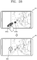
- control method may further include controlling the touch screen to display an image received from the camera subsequent to transmitting the reservation request; and displaying a pickup point guide image for guiding a region where the selected candidate vehicle can park in the image on the image.
- control method may further include setting a pickup point of the selected candidate vehicle based on a user input applied to the pickup point guide image.
- control method of controlling the operation of the foregoing mobile terminal may be carried out by an application stored in a storage means such as a memory of the mobile terminal.
- a driver may set his or her preferred type of passenger using a passenger condition and selectively receive only a reservation request of the passenger satisfying the passenger condition.
- a driver-friendly user interface may be provided.
- the driver may set his or her optimized passenger condition, and reset the passenger condition anytime and anywhere.
- a transportation system may guide a passenger crowded region or a no passenger region for a certain area in the vicinity from a point where the driver is located, and guide the driver to a region where the revenue is maximized. Through this, the driver may visually confirm at which point and at which time zone there is a large number of passengers. Furthermore, a plurality of vehicles may be efficiently deployed by big data.
- a passenger who wants to use the transportation service may create his or her own carsharing schedule. Since the sharing schedule is shared with a third party, the passenger may not only book his or her own vehicle in advance, but also collect passengers to use the vehicle together. As a result, the passenger may lower the cost, and the driver may plan a transportation schedule and increase the revenue.
- an optimal seating arrangement may be determined according to the destination of each of passengers using carsharing, and the determined seating arrangement may be guided through the terminal of each of the passengers. Through this, the passengers may be seated at optimal seats suitable for their destinations, thereby preventing the inconvenience of carsharing in advance.
- FIG. 1A is a block diagram for explaining a mobile terminal associated with the present disclosure
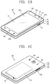
- FIGS. 1B through 1C are conceptual views illustrating an example in which a mobile terminal associated with the present disclosure is seen from different directions;
- FIG. 2 is a block diagram for explaining a transportation system of the present disclosure
- FIG. 3 is a flowchart for explaining a method of matching a passenger who is preferred to a driver, as an example of a control method carried out by the transportation system of FIG. 2 ;
- FIG. 4 is an exemplary view for explaining an operation of a driver terminal for resetting a passenger condition according to an embodiment of the present disclosure
- FIG. 5 is a flowchart illustrating a control method of providing a new type of user interface in providing a transportation service through a driver terminal;
- FIGS. 6 and 7 are exemplary views for explaining the control method of FIG. 5 ;
- FIG. 8 is a flowchart for explaining one step of FIG. 5 in more detail.
- FIG. 9 is an exemplary view for explaining the example.
- FIG. 10 is a flowchart illustrating a control method of providing a new type of user interface to a passenger in providing a transportation service through a client terminal;
- FIG. 11 are exemplary views for explaining the control method of FIG. 10 ;
- FIG. 12 is a flowchart for explaining a method of arranging a meeting of drivers with passengers, as an example of a control method carried out by the transportation system of FIG. 2 ;
- FIG. 13 is an exemplary view of a client terminal or a driver terminal implementing the method of FIG. 12 ;
- FIG. 14 is a flowchart for explaining a method of allowing a driver to easily confirming his or her passengers, as an example of a control method carried out by the transportation system of FIG. 2 ;
- FIG. 15 are exemplary views for explaining the method of FIG. 14 ;
- FIG. 16 is a flowchart for explaining a method of obtaining objective data to evaluate drivers using a client terminal, as an example of a control method carried out by the transportation system of FIG. 2 ;
- FIGS. 17A and 17B are conceptual views for explaining a shared economy using a transportation service
- FIG. 18 is a flowchart for explaining a method of allowing a transportation system to provide a carsharing service according to an embodiment of the present disclosure
- FIG. 19 is a flowchart illustrating a control method of a mobile terminal providing a transportation service according to an example of the present disclosure
- FIGS. 20A through 20E are conceptual views for explaining an operation of a mobile terminal according to the control method of FIG. 19 ;
- FIG. 21 is a flowchart for explaining a method of generating a new carsharing schedule using a mobile terminal
- FIG. 22 is a flowchart for explaining a control method of a mobile terminal capable of providing a driver-oriented transportation service other than a passenger-oriented transportation service;
- FIG. 23 is a conceptual view for explaining the control method of FIG. 22 ;
- FIG. 24 is a flowchart for explaining a method of setting a condition of a vehicle request by a client terminal
- FIGS. 25A and 25B are exemplary views for explaining an operation of a client terminal according to the control method of FIG. 24 ;
- FIG. 26 is an exemplary view for explaining a method of resetting a condition of a vehicle request based on a user input
- FIGS. 27A and 27B are conceptual views for explaining an operation of a client terminal related to baggage.
- FIG. 28 is an exemplary view for explaining an operation of a client terminal that guides a pickup point for a passenger.
- a singular representation may include a plural representation as far as it represents a definitely different meaning from the context.
- Mobile terminals described herein may include cellular phones, smart phones, laptop computers, digital broadcasting terminals, personal digital assistants (PDAs), portable multimedia players (PMPs), navigators, slate PCs, tablet PCs, ultra books, wearable devices (for example, smart watches, smart glasses, head mounted displays (HMDs)), and the like.
- PDAs personal digital assistants
- PMPs portable multimedia players
- slate PCs slate PCs
- tablet PCs ultra books
- wearable devices for example, smart watches, smart glasses, head mounted displays (HMDs)
- FIG. 1A is a block diagram of a mobile terminal in accordance with the present disclosure
- FIGS. 1B and 1C are conceptual views of one example of the mobile terminal, viewed from different directions.
- the mobile terminal 100 may include components, such as a wireless communication unit 110 , an input unit 120 , a sensing unit 140 , an output unit 150 , an interface unit 160 , a memory 170 , a controller 180 , a power supply unit 190 and the like.
- FIG. 1A illustrates the mobile terminal having various components, but it may be understood that implementing all of the illustrated components is not a requirement. Greater or fewer components may alternatively be implemented.
- the wireless communication unit 110 of those components may typically include one or more modules which permit wireless communications between the mobile terminal 100 and a wireless communication system, between the mobile terminal 100 and another mobile terminal 100 , or between the mobile terminal 100 and a network within which another mobile terminal 100 (or an external server) is located.
- the wireless communication unit 110 may include one or more modules that connect the mobile terminal 100 to one or more networks.
- the wireless communication unit 110 may include at least one of a broadcast receiving module 111 , a mobile communication module 112 , a wireless Internet module 113 , a short-range communication module 114 , a location information module 115 and the like.
- the input unit 120 may include a camera 121 for inputting an image signal, a microphone 122 or an audio input module for inputting an audio signal, or a user input unit 123 (for example, a touch key, a push key (or a mechanical key), etc.) for allowing a user to input information. Audio data or image data collected by the input unit 120 may be analyzed and processed by a user's control command.
- the sensing unit 140 may include at least one sensor which senses at least one of internal information of the mobile terminal, a surrounding environment of the mobile terminal and user information.
- the sensing unit 140 may include a proximity sensor 141 , an illumination sensor 142 , a touch sensor, an acceleration sensor, a magnetic sensor, (G-sensor), gyroscope sensor, motion sensor, RGB sensor, infrared sensor (IR sensor: An infrared sensor, a finger scan sensor, an ultrasonic sensor, an optical sensor (for example, see camera 121 ), a microphone (see 922 ), a battery gauge), An environmental sensor (for example, a barometer, a hygrometer, a thermometer, a radiation sensor, a heat sensor, a gas sensor, etc.), a chemical sensor (e.g., an electronic nose, a healthcare sensor, One may be included.
- the mobile terminal 100 may be configured to utilize information obtained from sensing unit 140 , and in particular, information obtained from one or more sensors of the sensing unit 140
- the output unit 150 may be configured to output an audio signal, a video signal or a tactile signal.
- the output unit 150 may include a display unit 151 , an audio output unit 152 , a haptic module 153 , an optical output unit 154 and the like.
- the display unit 151 may have an inter-layered structure or an integrated structure with a touch sensor in order to facilitate a touch screen.
- the touch screen may provide an output interface between the mobile terminal 100 and a user, as well as functioning as the user input unit 123 which provides an input interface between the mobile terminal 100 and the user.
- the interface unit 160 serves as an interface with various types of external devices that can be coupled to the mobile terminal 100 .
- the interface unit 160 may include wired or wireless headset ports, external power supply ports, wired or wireless data ports, memory card ports, ports for connecting a device having an identification module, audio input/output (I/O) ports, video I/O ports, earphone ports, or the like.
- the mobile terminal 100 may execute an appropriate control associated with a connected external device, in response to the external device being connected to the interface unit 160 .
- the memory 170 stores data supporting various functions of the mobile terminal 100 .
- the memory 170 is typically implemented to store data to support various functions or features of the mobile terminal 100 .
- the memory 170 may be configured to store application programs executed in the mobile terminal 100 , data or instructions for operations of the mobile terminal 100 , and the like. At least some of those application programs may be downloaded from an external server via wireless communication. Some others of those application programs may be installed within the mobile terminal 100 at the time of being shipped for basic functions of the mobile terminal 100 (for example, receiving a call, placing a call, receiving a message, sending a message, etc.).
- the application programs may be stored in the memory 170 , installed in the mobile terminal 100 , and executed by the controller 180 to perform an operation (or a function) of the mobile terminal 100 .
- the controller 180 may typically control an overall operation of the mobile terminal 100 in addition to the operations associated with the application programs.
- the controller 180 may provide or process information or functions appropriate for a user in a manner of processing signals, data, information and the like, which are input or output by the aforementioned components, or activating the application programs stored in the memory 170 .
- controller 180 may control at least part of the components illustrated in FIG. 1A , in order to drive the application programs stored in the memory 170 .
- controller 180 may drive the application programs by combining at least two of the components included in the mobile terminal 100 for operation.
- the power supply unit 190 may receive external power or internal power and supply appropriate power required for operating respective elements and components included in the mobile terminal 100 under the control of the controller 180 .
- the power supply unit 190 may include a battery, and the battery may be an embedded battery or a replaceable battery.
- At least part of those elements and components may be combined to implement operation and control of the mobile terminal or a control method of the mobile terminal according to various exemplary embodiments described herein. Furthermore, the operation and control or the control method of the mobile terminal may be implemented in the mobile terminal in such a manner of activating at least one application program stored in the memory 170 .
- the broadcast receiving module 111 of the wireless communication unit 110 may receive a broadcast signal and/or broadcast associated information from an external broadcast managing entity via a broadcast channel.
- the broadcast channel may include a satellite channel and/or a terrestrial channel.
- At least two broadcast receiving modules 111 may be provided in the mobile terminal 100 to simultaneously receive at least two broadcast channels or switch the broadcast channels.
- the mobile communication module 112 may transmit/receive wireless signals to/from at least one of network entities, for example, a base station, an external mobile terminal, a server, and the like, on a mobile communication network, which is constructed according to technical standards or transmission methods for mobile communications (for example, Global System for Mobile communication (GSM), Code Division Multi Access (CDMA), Code Division Multi Access 2000 (CDMA2000), Enhanced Voice-Data Optimized or Enhanced Voice-Data Only (EV-DO), Wideband CDMA (WCDMA), High Speed Downlink Packet Access (HSDPA), High Speed Uplink Packet Access (HSUPA), Long Term Evolution (LTE), Long Term Evolution-Advanced (LTE-A), etc.)
- GSM Global System for Mobile communication
- CDMA Code Division Multi Access
- CDMA2000 Code Division Multi Access 2000
- EV-DO Enhanced Voice-Data Optimized or Enhanced Voice-Data Only
- WCDMA Wideband CDMA
- HSDPA High Speed Downlink Packet Access
- HSUPA High Speed Up
- the wireless signals may include audio call signal, video (telephony) call signal, or various formats of data according to transmission/reception of text/multimedia messages.
- the wireless Internet module 113 refers to a module for supporting wireless Internet access, and may be built-in or externally installed on the mobile terminal 100 .
- the wireless Internet module 113 may transmit and/or receive wireless signals via communication networks according to wireless Internet technologies.
- wireless Internet access may include Wireless LAN (WLAN), Wireless-Fidelity (Wi-Fi), Wireless Fidelity Direct (Wi-Fi Direct), Digital Living Network Alliance (DLNA), Wireless Broadband (WiBro), World Interoperability for Microwave Access (WiMAX), High Speed Downlink Packet Access (HSDPA), High Speed Uplink Packet Access (HSUPA), LTE (Long Term Evolution), LTE-A (Long Term Evolution-Advanced), and the like.
- the wireless Internet module 113 may transmit/receive data according to at least one wireless Internet technology within a range including even Internet technologies which are not aforementioned.
- the wireless Internet module 113 which performs the wireless Internet access via the mobile communication network may be understood as a type of the mobile communication module 112 .
- the short-range communication module 114 denotes a module for short-range communications. Suitable technologies for implementing the short-range communications may include BLUETOOTHTM, Radio Frequency IDentification (RFID), Infrared Data Association (IrDA), Ultra-WideBand (UWB), ZigBee, Near Field Communication (NFC), Wireless-Fidelity (Wi-Fi), Wi-Fi Direct, and the like.
- the short-range communication module 114 may support wireless communications between the mobile terminal 100 and a wireless communication system, between the mobile terminal 100 and another mobile terminal 100 , or between the mobile terminal and a network where another mobile terminal 100 (or an external server) is located, via wireless personal area networks.
- the short-range communication module 114 denotes a module for short-range communications.
- the another mobile terminal 100 may be a wearable device, for example, a smart watch, smart glasses or a head mounted display (HMD), which is able to exchange data with the mobile terminal 100 (or to like data with the mobile terminal 100 ).
- the short-range communication module 114 may sense (recognize) a wearable device, which is able to communicate with the mobile terminal), near the mobile terminal 100 .
- the controller 180 may transmit at least part of data processed in the mobile terminal 100 to the wearable device via the short-range communication module 114 .
- a user of the wearable device may use the data processed in the mobile terminal 100 on the wearable device. For example, when a call is received in the mobile terminal 100 , the user may answer the call using the wearable device. Also, when a message is received in the mobile terminal 100 , the user can check the received message using the wearable device.
- the location information module 115 is generally configured to detect, calculate, derive or otherwise identify a position of the mobile terminal.
- the location information module 115 includes a Global Position System (GPS) module, a Wi-Fi module, or both.
- GPS Global Position System
- Wi-Fi Wireless Fidelity
- a position of the mobile terminal may be acquired using a signal sent from a GPS satellite.
- AP wireless access point
- the location information module 115 may perform any function of the other modules of the wireless communication unit 110 to obtain data on the location of the mobile terminal.
- the location information module 115 may not be necessarily limited to a module for directly calculating or acquiring the location of the mobile terminal.
- the input unit 120 may be configured to provide an audio or video signal (or information) input to the mobile terminal or information input by a user to the mobile terminal.
- the mobile terminal 100 may include one or a plurality of cameras 121 .
- the camera 121 processes a image frame, such as still picture or video, obtained by an image sensor in a video phone call or image capturing mode. The processed image frames may be displayed on the display unit 151 .
- the plurality of cameras 121 disposed in the mobile terminal 100 may be arranged in a matrix configuration. By use of the cameras 121 having the matrix configuration, a plurality of image information having various angles or focal points may be input into the mobile terminal 100 .
- the cameras 121 may be located in a stereoscopic arrangement to acquire left and right images for implementing a stereoscopic image.
- the microphone 122 may process an external audio signal into electric audio data.
- the processed audio data may be utilized in various manners according to a function being executed in the mobile terminal 100 (or an application program being executed).
- the microphone 122 may include assorted noise removing algorithms to remove noise generated in the course of receiving the external audio signal.
- the user input unit 123 may receive information input by a user. When information is input through the user input unit 123 , the controller 180 may control an operation of the mobile terminal 100 to correspond to the input information.
- the user input unit 123 may include one or more of a mechanical input element (for example, a key, a button located on a front and/or rear surface or a side surface of the mobile terminal 100 , a dome switch, a jog wheel, a jog switch, and the like), or a touch-sensitive input, among others.
- the touch-sensitive input means may be a virtual key, a soft key or a visual key, which is displayed on a touch screen through software processing, or a touch key which is disposed on a portion except for the touch screen.
- the virtual key or the visual key may be displayable on the touch screen in various shapes, for example, graphic, text, icon, video or a combination thereof.
- the sensing unit 140 may sense at least one of internal information of the mobile terminal, surrounding environment information of the mobile terminal and user information, and generate a sensing signal corresponding to it.
- the controller 180 may control an operation of the mobile terminal 100 or execute data processing, a function or an operation associated with an application program installed in the mobile terminal based on the sensing signal.
- description will be given in more detail of representative sensors of various sensors which may be included in the sensing unit 140 .
- a proximity sensor 141 refers to a sensor to sense presence or absence of an object approaching to a surface to be sensed, or an object disposed near a surface to be sensed, by using an electromagnetic field or infrared rays without a mechanical contact.
- the proximity sensor 141 may be arranged at an inner region of the mobile terminal covered by the touch screen, or near the touch screen.
- the proximity sensor 141 may include any of a transmissive type photoelectric sensor, a direct reflective type photoelectric sensor, a mirror reflective type photoelectric sensor, a high-frequency oscillation proximity sensor, a capacitance type proximity sensor, a magnetic type proximity sensor, an infrared rays proximity sensor, and the like.
- the proximity sensor 141 may sense proximity of a pointer to the touch screen by changes of an electromagnetic field, which is responsive to an approach of an object with conductivity.
- the touch screen may also be categorized as a proximity sensor.
- proximity touch a state that the pointer is positioned to be proximate onto the touch screen without contact
- contact touch a state that the pointer substantially comes in contact with the touch screen
- position corresponding to the proximity touch of the pointer on the touch screen such position will correspond to a position where the pointer faces perpendicular to the touch screen upon the proximity touch of the pointer.
- the proximity sensor 141 may sense proximity touch, and proximity touch patterns (e.g., distance, direction, speed, time, position, moving state, etc.).
- the controller 180 may process data (or information) corresponding to the proximity touches and the proximity touch patterns sensed by the proximity sensor 141 , and output visual information corresponding to the process data on the touch screen.
- the controller 180 may control the mobile terminal 100 to execute different operations or process different data (or information) according to whether a touch with respect to the same point on the touch screen is either a proximity touch or a contact touch.
- a touch sensor may sense a touch (or touch input) applied onto the touch screen (or the display unit 151 ) using at least one of various types of touch methods, such as a resistive type, a capacitive type, an infrared type, a magnetic field type, and the like.
- the touch sensor may be configured to convert changes of pressure applied to a specific part of the display unit 151 or a capacitance occurring from a specific part of the display unit 151 , into electric input signals. Also, the touch sensor may be configured to sense not only a touched position and a touched area, but also touch pressure.
- the touch object body may be a finger, a touch pen or stylus pen, a pointer, or the like as an object through which a touch is applied to the touch sensor.
- a touch controller When a touch input is sensed by a touch sensor, corresponding signals may be transmitted to a touch controller.
- the touch controller may process the received signals, and then transmit corresponding data to the controller 180 .
- the controller 180 may sense which region of the display unit 151 has been touched.
- the touch controller may be a component separate from the controller 180 or the controller 180 itself.
- the controller 180 may execute a different control or the same control according to a type of an object which touches the touch screen (or a touch key provided in addition to the touch screen). Whether to execute the different control or the same control according to the object which gives a touch input may be decided based on a current operating state of the mobile terminal 100 or a currently executed application program.
- the touch sensor and the proximity sensor may be executed individually or in combination, to sense various types of touches, such as a short (or tap) touch, a long touch, a multi-touch, a drag touch, a flick touch, a pinch-in touch, a pinch-out touch, a swype touch, a hovering touch, and the like.
- An ultrasonic sensor may be configured to recognize position information relating to a sensing object by using ultrasonic waves.
- the controller 180 may calculate a position of a wave generation source based on information sensed by an illumination sensor and a plurality of ultrasonic sensors. Since light is much faster than ultrasonic waves, a time for which the light reaches the optical sensor may be much shorter than a time for which the ultrasonic wave reaches the ultrasonic sensor.
- the position of the wave generation source may be calculated using this fact. For instance, the position of the wave generation source may be calculated using the time difference from the time that the ultrasonic wave reaches the sensor based on the light as a reference signal.
- the camera 121 constructing the input unit 120 may be a type of camera sensor.
- the camera sensor may include at least one of a photo sensor (or image sensor) and a laser sensor.
- Implementing the camera 121 with a laser sensor may allow detection of a touch of a physical object with respect to a 3D stereoscopic image.
- the camera 121 and the laser sensor may be combined to detect a touch of the sensing object with respect to a 3D stereoscopic image.
- the photo sensor is integrated with photo diodes and transistors in the rows and columns thereof, and a content placed on the photo sensor may be scanned by using an electrical signal that is changed according to the amount of light applied to the photo diode.
- the photo sensor may calculate the coordinates of the sensing object according to variation of light to thus obtain position information of the sensing object.
- the display unit 151 may output information processed in the mobile terminal 100 .
- the display unit 151 may display execution screen information of an application program driven in the mobile terminal 100 or user interface (UI) and graphic user interface (GUI) information in response to the execution screen information.
- UI user interface
- GUI graphic user interface
- the display unit 151 may also be implemented as a stereoscopic display unit for displaying stereoscopic images.
- the stereoscopic display unit may employ a stereoscopic display scheme such as stereoscopic scheme (a glass scheme), an auto-stereoscopic scheme (glassless scheme), a projection scheme (holographic scheme), or the like.
- a stereoscopic display scheme such as stereoscopic scheme (a glass scheme), an auto-stereoscopic scheme (glassless scheme), a projection scheme (holographic scheme), or the like.
- the audio output module 152 is generally configured to output audio data. Such audio data may be obtained from any of a number of different sources, such that the audio data may be received from the wireless communication unit 110 or may have been stored in the memory 170 . Also, the audio output unit 152 may also provide audible output signals related to a particular function (e.g., a call signal reception sound, a message reception sound, etc.) performed by the mobile terminal 100 .
- the audio output module 152 may include a receiver, a speaker, a buzzer or the like.
- a haptic module 153 may generate various tactile effects the that user may feel.
- a typical example of the tactile effect generated by the haptic module 153 may be vibration.
- Strength, pattern and the like of the vibration generated by the haptic module 153 may be controllable by a user selection or setting of the controller.
- the haptic module 153 may output different vibrations in a combining manner or a sequential manner.
- the haptic module 153 may generate various other tactile effects, including an effect by stimulation such as a pin arrangement vertically moving with respect to a contact skin, a spray force or suction force of air through a jet orifice or a suction opening, a touch on the skin, a contact of an electrode, electrostatic force, etc., an effect by reproducing the sense of cold and warmth using an element that can absorb or generate heat, and the like.
- an effect by stimulation such as a pin arrangement vertically moving with respect to a contact skin, a spray force or suction force of air through a jet orifice or a suction opening, a touch on the skin, a contact of an electrode, electrostatic force, etc.
- the haptic module 153 may be configured to transmit tactile effects through a users direct contact, or a user's muscular sense using a finger or a hand. Two or more haptic modules 153 may be provided according to the particular configuration of the mobile terminal 100 .
- An optical output module 154 may output a signal for indicating an event generation using light of a light source. Examples of events generated in the mobile terminal 100 may include a message reception, a call signal reception, a missed call, an alarm, a schedule notice, an email reception, an information reception through an application, and the like.
- a signal output by the optical output module 154 may be implemented in such a manner that the mobile terminal emits monochromatic light or light with a plurality of colors.
- the signal output may be terminated as the mobile terminal senses that a user has checked the generated event, for example.
- the interface unit 160 serves as an interface for external devices to be connected with the mobile terminal 100 .
- the interface unit 160 can receive data transmitted from an external device, receive power to transfer to elements and components within the mobile terminal 100 , or transmit internal data of the mobile terminal 100 to such external device.
- the interface unit 160 may include wired or wireless headset ports, external power supply ports, wired or wireless data ports, memory card ports, ports for connecting a device having an identification module, audio input/output (I/O) ports, video I/O ports, earphone ports, or the like.
- the identification module may be a chip that stores various information for authenticating authority of using the mobile terminal 100 and may include a user identity module (UIM), a subscriber identity module (SIM), a universal subscriber identity module (USIM), and the like.
- the device having the identification module (also referred to herein as an “identifying device”) may take the form of a smart card. Accordingly, the identifying device may be connected with the terminal 100 via the interface unit 160 .
- the interface unit 160 may serve as a passage to allow power from the cradle to be supplied to the mobile terminal 100 therethrough or may serve as a passage to allow various command signals input by the user from the cradle to be transferred to the mobile terminal therethrough.
- Such various command signals or power inputted from the cradle may operate as signals for recognizing that the mobile terminal 100 has accurately been mounted to the cradle.
- the memory 170 can store programs to support operations of the controller 180 and store input/output data (for example, phonebook, messages, still images, videos, etc.).
- the memory 170 may store data related to various patterns of vibrations and audio which are output in response to touch inputs on the touch screen.
- the memory 170 may include at least one type of storage medium including a Flash memory, a hard disk, a multimedia card micro type, a card-type memory (e.g., SD or DX memory, etc), a Random Access Memory (RAM), a Static Random Access Memory (SRAM), a Read-Only Memory (ROM), an Electrically Erasable Programmable Read-Only Memory (EEPROM), a Programmable Read-Only memory (PROM), a magnetic memory, a magnetic disk, and an optical disk.
- the mobile terminal 100 may be operated in relation to a web storage device that performs the storage function of the memory 170 over the Internet.
- the controller 180 may typically control the general operations of the mobile terminal 100 .
- the controller 180 may set or to release a lock state for restricting a user from inputting a control command with respect to applications when a state of the mobile terminal meets a preset condition.
- controller 180 may also perform controlling and processing associated with voice calls, data communications, video calls, and the like, or perform pattern recognition processing to recognize a handwriting input or a picture drawing input performed on the touch screen as characters or images, respectively.
- controller 180 may control one or combination of those components in order to implement various exemplary embodiment disclosed herein on the mobile terminal 100 .
- the power supply unit 190 may receive external power or internal power and supply appropriate power required for operating respective elements and components included in the mobile terminal 100 under the control of the controller 180 .
- the power supply unit 190 may include a battery, which is typically rechargeable or be detachably coupled to the terminal body for charging.
- the power supply unit 190 may include a connection port.
- the connection port may be configured as one example of the interface unit 160 to which an external (re)charger for supplying power to recharge the battery is electrically connected.
- the power supply unit 190 may be configured to recharge the battery in a wireless manner without use of the connection port.
- the power supply unit 190 may receive power, transferred from an external wireless power transmitter, using at least one of an inductive coupling method which is based on magnetic induction or a magnetic resonance coupling method which is based on electromagnetic resonance.
- the mobile terminal 100 is described with reference to a bar-type terminal body.
- the present disclosure may not be necessarily limited to this, and may be also applicable to various structures such as a watch type, a clip type, a glasses type, a folder type in which two or more bodies are coupled to each other in a relatively movable manner, a slide type, a swing type, a swivel type, and the like.
- the description in association with a specific type of mobile terminal or on a specific type of mobile terminal will be also typically applied to another type of mobile terminal.
- the terminal body may be understood as a conception which indicates the mobile terminal 100 as at least one assembly.
- the mobile terminal 100 may include a case (for example, a frame, a housing, a cover, etc.) constituting the appearance thereof.
- the case may be divided into a front case 101 and a rear case 102 .
- Various electronic components may be incorporated into a space formed between the front case 101 and the rear case 102 .
- At least one middle case may be additionally disposed between the front case 101 and the rear case 102
- a display unit 151 may be disposed on a front surface of the terminal body to output information. As illustrated, a window 151 a of the display unit 151 may be mounted to the front case 101 so as to form the front surface of the terminal body together with the front case 101 .
- electronic components may also be mounted to the rear case 102 .
- Examples of those electronic components mounted to the rear case 102 may include a detachable battery, an identification module, a memory card and the like.
- a rear cover 103 for covering the electronic components mounted may be detachably coupled to the rear case 102 . Therefore, when the rear cover 103 is detached from the rear case 102 , the electronic components mounted to the rear case 102 may be externally exposed.
- the rear cover 103 when the rear cover 103 is coupled to the rear case 102 , a side surface of the rear case 102 may be partially exposed. In some cases, upon the coupling, the rear case 102 may also be completely shielded by the rear cover 103 . In some embodiments, the rear cover 103 may include an opening for externally exposing a camera 121 b or an audio output module 152 b.
- the cases 101 , 902 , 903 may be formed by injection-molding synthetic resin or may be formed of a metal, for example, stainless steel (STS), titanium (Ti), or the like.
- STS stainless steel
- Ti titanium
- the mobile terminal 100 may be configured such that one case forms the inner space.
- a mobile terminal 100 having a uni-body formed in such a manner that synthetic resin or metal extends from a side surface to a rear surface may also be implemented.
- the mobile terminal 100 may include a waterproofing unit (not shown) for preventing an introduction of water into the terminal body.
- the waterproofing unit may include a waterproofing member which is located between the window 151 a and the front case 101 , between the front case 101 and the rear case 102 , or between the rear case 102 and the rear cover 103 , to hermetically seal an inner space when those cases are coupled.
- the mobile terminal 100 may include a display unit 151 , first and second audio output modules 152 a and 152 b , a proximity sensor 141 , an illumination sensor 152 , an optical output module 154 , first and second cameras 121 a and 121 b , first and second manipulation units 123 a and 123 b , a microphone 122 , an interface unit 160 and the like.
- the display unit 151 , the first audio output module 152 a , the proximity sensor 141 , the illumination sensor 142 , the optical output module 154 , the first camera 121 a and the first manipulation unit 123 a are disposed on the front surface of the terminal body
- the second manipulation unit 123 b , the microphone 122 and the interface unit 160 are disposed on a side surface of the terminal body
- the second audio output module 152 b and the second camera 121 b are disposed on a rear surface of the terminal body, with reference to FIGS. 1B and 1C .
- the foregoing configuration may not be necessarily limited to the arrangement.
- the foregoing configuration may be excluded, substituted or disposed on another surface if necessary.
- the first manipulation unit 123 a may not be disposed on the front surface of the terminal body, and the second audio output module 152 b may be disposed on the side surface other than the rear surface of the terminal body.
- the display unit 151 may output information processed in the mobile terminal 100 .
- the display unit 151 may display execution screen information of an application program driven in the mobile terminal 100 or user interface (UI) and graphic user interface (GUI) information in response to the execution screen information.
- UI user interface
- GUI graphic user interface
- the display unit 151 may include at least one of a liquid crystal display (LCD), a thin film transistor-liquid crystal display (TFT-LCD), an organic light emitting diode (OLED), a flexible display, a 3-dimensional (3D) display, and an e-ink display.
- LCD liquid crystal display
- TFT-LCD thin film transistor-liquid crystal display
- OLED organic light emitting diode
- flexible display a 3-dimensional (3D) display
- 3D 3-dimensional
- the display unit 151 may be implemented in two or more in number according to a configured aspect of the mobile terminal 100 . For instance, a plurality of the display units 151 may be arranged on one surface to be spaced apart from or integrated with each other, or may be arranged on different surfaces.
- the display unit 151 may include a touch sensor which senses a touch onto the display unit so as to receive a control command in a touching manner.
- the touch sensor may be configured to sense this touch and the controller 180 may generate a control command corresponding to the touch.
- the content which is input in the touching manner may be a text or numerical value, or a menu item which can be indicated or designated in various modes.
- the touch sensor may be configured in a form of a film having a touch pattern, disposed between the window 151 a and a display on a rear surface of the window 151 a , or a metal wire which is patterned directly on the rear surface of the window 151 a .
- the touch sensor may be integrally formed with the display.
- the touch sensor may be disposed on a substrate of the display or within the display.
- the display unit 151 may form a flexible touch screen along with the touch sensor, and in this case, the touch screen may function as the user input unit 123 (refer to FIG. 1A ). Therefore, the touch screen may replace at least some of the functions of the first manipulation unit 123 a.
- the first audio output module 152 a may be implemented in the form of a receiver for transferring voice sounds to the user's ear or a loud speaker for outputting various alarm sounds or multimedia reproduction sounds.
- the window 151 a of the display unit 151 may include a sound hole for emitting sounds generated from the first audio output module 152 a .
- the present disclosure may not be limited to this. It may also be configured such that the sounds are released along an assembly gap between the structural bodies (for example, a gap between the window 151 a and the front case 101 ). In this case, a hole independently formed to output audio sounds may not be seen or is otherwise hidden in terms of appearance, thereby further simplifying the appearance and manufacturing of the mobile terminal 100 .
- the optical output module 154 may output light for indicating an event generation. Examples of the event generated in the mobile terminal 100 may include a message reception, a call signal reception, a missed call, an alarm, a schedule notice, an email reception, information reception through an application, and the like. When a user's event check is sensed, the controller 180 may control the optical output unit 154 to end the output of light.
- the first camera 121 a may process video frames such as still or moving images obtained by the image sensor in a video call mode or a capture mode.
- the processed video frames may be displayed on the display unit 151 or stored in the memory 170 .
- the first and second manipulation units 123 a and 123 b are examples of the user input unit 123 , which may be manipulated by a user to input a command for controlling the operation of the mobile terminal 100 .
- the first and second manipulation units 123 a and 123 b may employ any method if it is a tactile manner allowing the user to perform manipulation with a tactile feeling such as touch, push, scroll or the like.
- the first and second manipulation units 123 a and 123 b may also employ a method of allowing the user to perform manipulation without a tactile feeling through a proximity touch, a hovering touch, or the like.
- first manipulation unit 123 a is a touch key, but the present disclosure may not be necessarily limited to this.
- the first manipulation unit 123 a may be configured with a mechanical key, or a combination of a touch key and a push key.
- the content received by the first and second manipulation units 123 a and 123 b may be set in various ways.
- the first manipulation unit 123 a may be used by the user to input a command such as menu, home key, cancel, search, or the like
- the second manipulation unit 123 b may be used by the user to input a command, such as controlling a volume level being output from the first or second audio output module 152 a or 152 b , switching into a touch recognition mode of the display unit 151 , or the like.
- a rear input unit (not shown) may be disposed on the rear surface of the terminal body.
- the rear input unit may be manipulated by a user to input a command for controlling an operation of the mobile terminal 100 .
- the content input may be set in various ways.
- the rear input unit may be used by the user to input a command, such as power on/off, start, end, scroll or the like, controlling a volume level being output from the first or second audio output module 152 a or 152 b , switching into a touch recognition mode of the display unit 151 , or the like.
- the rear input unit may be implemented into a form allowing a touch input, a push input or a combination thereof.
- the rear input unit may be disposed to overlap the display unit 151 of the front surface in a thickness direction of the terminal body.
- the rear input unit may be disposed on an upper end portion of the rear surface of the terminal body such that a user can easily manipulate it using a forefinger when the user grabs the terminal body with one hand.
- the present disclosure may not be limited to this, and the position of the rear input unit may be changeable.
- a new user interface may be implemented using the rear input unit.
- the aforementioned touch screen or the rear input unit may substitute for at least part of functions of the first manipulation unit 123 a located on the front surface of the terminal body. Accordingly, when the first manipulation unit 123 a is not disposed on the front surface of the terminal body, the display unit 151 may be implemented to have a larger screen.
- the mobile terminal 100 may include a fingerprint recognition sensor for recognizing a user's fingerprint, and the controller 180 may use fingerprint information sensed through the finger recognition sensor as an authentication means.
- the finger scan sensor may be installed in the display unit 151 or the user input unit 123 .
- the microphone 122 may be formed to receive the user's voice, other sounds, and the like.
- the microphone 122 may be provided at a plurality of places, and configured to receive stereo sounds.
- the interface unit 160 may serve as a path allowing the mobile terminal 100 to exchange data with external devices.
- the interface unit 160 may be at least one of a connection terminal for connecting to another device (for example, an earphone, an external speaker, or the like), a port for near field communication (for example, an Infrared Data Association (IrDA) port, a Bluetooth port, a wireless LAN port, and the like), or a power supply terminal for supplying power to the mobile terminal 100 .
- the interface unit 160 may be implemented in the form of a socket for accommodating an external card, such as Subscriber Identification Module (SIM), User Identity Module (UIM), or a memory card for information storage.
- SIM Subscriber Identification Module
- UIM User Identity Module
- the second camera 121 b may be further mounted to the rear surface of the terminal body.
- the second camera 121 b may have an image capturing direction, which is substantially opposite to the direction of the first camera unit 121 a.
- the second camera 121 b may include a plurality of lenses arranged along at least one line.
- the plurality of lenses may also be arranged in a matrix configuration.
- the cameras may be referred to as an ‘array camera.’
- the second camera 121 b is implemented as the array camera, images may be captured in various manners using the plurality of lenses and images with better qualities may be obtained.
- a flash 124 may be disposed adjacent to the second camera 121 b .
- the flash 124 may illuminate the subject.
- the second audio output module 152 b may further be disposed on the terminal body.
- the second audio output module 152 b may implement stereophonic sound functions in conjunction with the first audio output module 152 a , and may be also used for implementing a speaker phone mode for call communication.
- At least one antenna for wireless communication may be disposed on the terminal body.
- the antenna may be installed in the terminal body or formed on the case.
- an antenna which configures a part of the broadcast receiving to module 111 may be retractable into the terminal body.
- an antenna may be formed in a form of film to be attached onto an inner surface of the rear cover 103 or a case including a conductive material may serve as an antenna.
- a power supply unit 190 (refer to FIG. 1A ) for supplying power to the mobile terminal 100 may be disposed on the terminal body.
- the power supply unit 190 may include a batter 191 which is mounted in the terminal body or detachably coupled to an outside of the terminal body.
- the battery 191 may receive power via a power source cable connected to the interface unit 160 . Also, the battery 191 may be (re)chargeable in a wireless manner using a wireless charger.
- the wireless charging may be implemented by magnetic induction or electromagnetic resonance.
- the drawing illustrates that the rear cover 103 is coupled to the rear case 102 for shielding the battery 191 , so as to prevent separation of the battery 191 and protect the battery 191 from an external impact or foreign materials.
- the rear case 103 may be detachably coupled to the rear case 102 .
- An accessory for protecting an appearance or assisting or extending the functions of the mobile terminal 100 can also be provided on the mobile terminal 100 .
- a cover or pouch for covering or accommodating at least one surface of the mobile terminal 100 may be provided.
- the cover or pouch may cooperate with the display unit 151 to extend the function of the mobile terminal 100 .
- Another example of the accessory may be a touch pen for assisting or extending a touch input onto a touch screen.
- a mobile terminal may extend to a wearable device which is wearable on a human body, going beyond usually using the mobile terminal by a user with grabbing it with a hand.
- the wearable device may include a smart watch, a smart glass, a head mounted display (HMD), and so on.
- HMD head mounted display
- a wearable device may exchange data with (or cooperate with) another mobile terminal 100 .
- the short-range communication module 114 may sense (recognize) a wearable device, which is able to communicate with the mobile terminal), near the mobile terminal 100 .
- the controller 180 may transmit at least part of data processed in the mobile terminal 100 to the wearable device via the short-range communication module 114 .
- a user of the wearable device may use the data processed in the mobile terminal 100 on the wearable device. For example, when a call is received in the mobile terminal 100 , the user can answer the call using the wearable device. Also, when a message is received in the mobile terminal 100 , the user can check the received message using the wearable device.
- FIG. 2 is a block diagram for explaining a transportation system of the present disclosure
- the transportation system 200 includes a server 210 , a client terminal 220 installed with a passenger application 222 , and a driver terminal 230 installed with a driver application 232 .
- the client terminal 220 and the driver terminal 230 correspond to an example of the mobile terminal described above with reference to FIGS. 1A through 1C .
- the term terminal denotes either one of the client terminal 220 and the operation terminal 230 .
- the control method of the transportation system described below may be carried out through applications provided in the client terminal 220 and the driver terminal 230 , respectively. Specifically, the operation of the client terminal 220 may be executed through the passenger application 222 , and the operation of the driver terminal 230 may be executed through the driver application 232 .
- the transport system 200 is intended to provide transportation services to any passenger through any driver. Reservation, mediation, contact, transport and driver assessment may be done through the transportation system 200 .
- a reservation of a transportation service denotes allowing a passenger to request a vehicle to a departure point using the client terminal 220 .
- This request is referred to as a “vehicle request,” and the vehicle request is transmitted to the server 210 .
- the vehicle request may include a destination point to which the passenger wants to move, a type of vehicle, and a type of service the passenger wants to use.
- the vehicle request includes a condition of the vehicle request, and the server 210 searches for a candidate vehicle that matches the condition of the vehicle request, and transmits a reservation request to the searched candidate vehicle.
- the type of vehicle includes information related to the vehicle itself and an article contained in the vehicle.
- the information related to the vehicle itself may be a two-seater, a four-seater, a convertible, or the like, and the article contained in the vehicle may be a refrigerator, a wheelchair, an umbrella, or the like.
- the server searches for a vehicle that satisfies the type of vehicle.
- the type of service refers to a service provided through a vehicle.
- the type of the service may be a single ride service that uses a vehicle alone, a carsharing service that shares a vehicle with any third party, and the like.
- carsharing may be referred to as ride-sharing, but may also be referred to as vehicle-sharing, car-sharing, carpool, or the like.
- Mediation denotes that the server 210 assigns at least one vehicle to a passenger who has made a vehicle request in response to the vehicle request. Specifically, the server 210 searches for one or more driver terminals located within a predetermined range with respect to the position of the client terminal 220 , and requests a reservation for the driver terminal. This request is referred to as a “reservation request.” Then, when any one driver terminal 230 approves the reservation request, a mediation between the driver terminal 230 and the client terminal 220 is carried out. Through the mediation, the client terminal and the driver terminal are connected to each other to share various information for providing the service. For example, the location of each terminal may be shared with each other.
- a contact denotes a mediation meeting between the driver and the passenger.
- Various functions for a contact are executed in the client terminal 220 and the driver terminal 230 until boarding is carried out after the mediation is carried out. For example, a route moving to a departure point may be displayed on the driver terminal 230 , and a time period remaining until the vehicle arrives at the departure point may be displayed on the client terminal 220 .
- Transportation denotes moving from a departure point to a destination point after boarding is carried out.
- the passenger may change a route to the destination using his or her own client terminal 220 while moving, change the destination point itself, or set a waypoint.
- the client terminal 220 , the server 210 , and the driver terminal 230 operate organically, thereby changing the route and providing a transportation service to the changed route.
- a user interface that can evaluate the driver may be displayed on the client terminal 220 during transportation or after getting off.
- the server 210 may stores the evaluation for the driver and classify the driver using the stored big data.
- Each component of the transportation system 200 may be organically coupled to process location information generated from each terminal and provide a transportation service using the location information.
- Each of the components 210 - 230 of the transportation system 200 may exchange data with each other via a network, and may be organically connected to perform various functions associated with a transportation service.
- the logic of a transportation service may be implemented by various applications and/or hardware installed in each component. Specifically, the operation of the client terminal 220 may be executed through the passenger application 222 , and the operation of the driver terminal 230 may be executed through the driver application 232 .
- the server 210 is configured to mediate between the client terminal 220 and the driver terminal 230 .
- the server 210 may include a passenger database, a driver database, and a map database.
- the server 210 may select one or more driver terminals that satisfy a predetermined condition based on the position of the client terminal 220 , and transmit a reservation request to the selected driver terminal. At this time, a driver terminal located within a predetermined distance from a departure point or within a predetermined time period required to move to the departure point may be selected.
- the client terminal 220 and the driver terminal 230 execute a predetermined function to implement a contact between the passenger and the driver.
- the driver terminal 230 and the client terminal 220 may transmit and receive respective position information directly or indirectly through the server 210 .
- the client terminal 220 may display a position of the vehicle and a time period required for the vehicle to reach the departure point.
- the driver terminal 230 may display route guide information for leading the vehicle to the departure point.
- a travel path of the vehicle may be calculated by the server 210 or the driver terminal 230 .
- the driver terminal 230 and/or the client terminal 220 may transmit a board report to the server 210 . Then, transportation is carried out to the destination point, and cost is calculated according to at least one of a transportation distance and a transportation time. The cost may be calculated differently depending on the type of a vehicle and/or the type of a service provided in the transportation. The calculated cost will be paid by a pre-registered credit card or electronic money.
- FIG. 3 is a flowchart for explaining a method of matching a passenger who is preferred to a driver, as an example of a control method carried out by the transportation system of FIG. 2 .
- the driver terminal 230 generates a passenger condition of the driving terminal 230 based on a user input (S 310 ).
- the generated passenger condition is transmitted to the server 210 , and the server 210 registers the passenger condition (S 330 ).
- the passenger condition or passenger criteria denotes a condition in which a type of passenger who is intended by a user of the driver terminal 230 , namely, a driver, to provide a transportation service, is determined in advance.
- a reservation request of a passenger matching the passenger condition is selectively transmitted to the driver terminal.
- the passenger condition denotes a condition set by a driver's active intention.
- the passenger condition may be set differently according to the driver, and the passenger condition may be stored and managed in a driver database.
- the driver terminal may receive reservation requests from N passengers less than the M passengers that satisfy the passenger condition among the M passengers when the passenger condition is set.
- N reservation requests satisfying the passenger condition are transmitted to the driver terminal, and the remaining reservation requests that do not satisfy the passenger condition are filtered and not transmitted to the driver terminal. Accordingly, the driver may set his or her own passenger condition to selectively receive only a reservation request of his or her preferred passenger.
- the passenger condition may include at least one of the sex, age, nationality, usable language, passenger boarding region and passenger getting-off region of a passenger preferred by the user (or driver) of the driver terminal 230 .
- the driver terminal 230 may output a user interface for generating a passenger condition through the driver application 232 .
- a passenger condition setting screen may be displayed on a display of the driver terminal 230 , and the passenger condition may be generated by a touch input or various user inputs applied to the passenger condition setting screen.
- the server 210 searches for a vehicle matching the registered passenger condition in response to the vehicle request (S 340 ).
- the server 210 searches for one or more driver terminals located within a predetermined range based on the departure point of the client terminal 220 included in the vehicle request.
- the server 210 judges whether the vehicle request matches the passenger condition of the searched driver terminal, and determines whether or not to transmit a reservation request.
- the server 210 transmits a reservation request to the driver terminal 230 (S 350 ). Unless the vehicle request of the client terminal 220 matches the passenger condition of the driver terminal 230 , a reservation request is not transmitted to the driver terminal 230 . In other words, when a vehicle request is received from the client terminal 220 , the server 210 selectively transmits a reservation request to the driver terminal 230 according to whether the vehicle request matches the passenger condition of the driver terminal 230 .
- a reservation request is transmitted to each of the plurality of driver terminals.
- the driver terminal 230 outputs information corresponding to the reservation request, and determines whether to accept the reservation request based on a user input (S 360 ).
- the reservation request may include at least one of a departure point, a destination point, a route from the departure point to the destination point, and an estimated fare.
- the driver may determine whether or not to approve the reservation request based on information displayed on the driver terminal 230 .
- an approval request is transmitted from the driver terminal 230 to the server 210 .
- the server 210 mediates between the driver terminal 230 and the client terminal 220 in response to the approval request.
- a driver may set his or her preferred type of passenger using a passenger condition and selectively receive only a reservation request of the passenger satisfying the passenger condition.
- a driver-friendly user interface may be provided.
- a vehicle providing a transportation service may be an autonomous driving vehicle capable of driving according to the control of the software without a driver.
- a driver may set an autonomous driving vehicle or a manual driving vehicle on the passenger condition.
- the autonomous driving vehicle provides a transportation service in accordance with a driving command transmitted from the server 210 .
- the autonomous driving vehicle and the driver terminal 230 may communicate with each other, and the driver may check the present status or reservation status of transportation services through the driver terminal 230 .
- a transportation service is provided only when a driver boards the vehicle, and the server 230 may determine whether or not the driver boards the vehicle using information transmitted from the driver terminal 230 .
- the driver may set the passenger condition to at least one of “private use time” in which the driver himself or herself uses the vehicle and “taxi use time” in which the driver allows a third party other than the driver himself of herself to use his or her vehicle.
- the driver's vehicle may operate as an unmanned taxi during the taxi use time.
- the server 210 may take the control of the vehicle during a taxi use time according to the passenger condition to move the vehicle to the departure point of the client terminal 220 , and move the vehicle to the destination point when the passenger is boarding. Then, when it becomes a private use time in which the driver has to use the vehicle, the server 210 may end the provision of the transportation service and move the vehicle to a point where the driver needs it.
- the server 210 may generate and manage a vehicle schedule for a taxi use time so that the driver can use the vehicle during a private use time.
- FIG. 4 is an exemplary view for explaining an operation of a driver terminal for resetting a passenger condition according to an embodiment of the present disclosure.
- the driver terminal 230 may display a screen containing a passenger condition of the driver terminal 230 on a display of the driver terminal 230 . Then, the driver terminal 230 may reset the passenger condition of the driver terminal 230 based on a user input applied to the screen. In other words, the driver terminal 230 may provide a user interface for setting a passenger condition or resetting a preset passenger condition.
- the driver terminal 230 may display a passenger condition setting screen configured to set a passenger condition on the display unit.
- the passenger condition setting screen may include a plurality of items corresponding to a passenger condition, and the driver terminal 230 may newly set or reset each item based on the touch input on the passenger condition setting screen.
- a getting-off region setting screen for setting a getting-off region may be displayed.
- the getting-off region setting screen may include a map image divided into a plurality of zones. When a touch is applied to any one of the plurality of zones, the any one of the plurality of zones may be selected or deselected.
- zone A is set as a getting-off region, only a reservation request whose destination is within the zone A is selectively transmitted to the driver terminal 230 .
- the driver may set the getting-off region using a voice command or a virtual keypad displayed on the display of the driver terminal 230 .
- the driver may set his or her optimized passenger condition, and reset the passenger condition anytime and anywhere.
- the transportation system according to the present disclosure may guide the driver to maximize the revenue of the driver.
- a new type of user interface for maximizing revenue will be described in detail with reference to FIGS. 5 through 9 .
- FIG. 5 is a flowchart for explaining a control method of providing a new type of user interface in providing a transportation service through a driver terminal
- FIGS. 6 and 7 are exemplary views for explaining the control method of FIG. 5 .
- the server 210 may divide a predetermined region into a first region in which passengers are insufficient and a second region in which vehicles are insufficient based on information received at the server 210 (S 510 ).
- the information received at the server 210 is information received from at least one terminal included in the transportation system 200 .
- the information received at the server 210 is collected, stored, processed and analyzed in real time. According to the information received at the server 210 , a predetermined region is divided into a plurality of regions, and statistical data for each region is generated for each unit time period.
- the statistical data includes a number of passengers making a vehicle request, a number of vehicles waiting for a reservation request, a type of destination desired by a passenger, and a type of fare generated, based on a specific region at a specific time.
- a number of passengers may be calculated using a number of executions.
- a number of passengers may be calculated using a number of vehicle requests received from client terminals.
- a number of driver terminals executing a driver application being executed may be calculated to calculate a number of vehicles to provide transportation services.
- the server 210 may generate forecast data for the future based on the statistical data, and provide a transportation service based on at least one of the statistical data and the forecast data.
- the predetermined region may be divided into a first region and a second region.
- the predetermined region may include one or more first regions, and may include one or more second regions.
- the predetermined region may also include a third region that is neither the first region nor the second region.
- the first region may be defined as a region where a number of passengers is less than a number of vehicles by a first reference. For example, if the first reference is set to 100, then the relevant region is classified as a first region when a number of passengers is 50 in case where a number of vehicles is 200.
- the first region denotes a region having more vehicles than passengers, and corresponds to a region where vehicle exiting is required.
- the first reference may be modified in various ways.
- the second region may be defined as a region where a number of vehicles is less than a number of passengers by a second reference.
- the second reference may be different from the first reference, and modified in various ways according to the embodiment. For example, if the second reference is set to 50, then the relevant region is classified as a second region when a number of vehicles is 30 in case where a number of passengers is 100. In other words, the second region denotes a region having more passengers than vehicles, and corresponds to a region where vehicle entering is required.
- the predetermined region may also include a third region that is neither the first region nor the second region.
- the predetermined region may vary depending on a point where the driver terminal is located.
- the server 210 may specify a predetermined region based on the location of the driver terminal 230 , and transmit only information on the specified predetermined region to the driver terminal 230 . It is because much time and money are consumed when information of all the regions managed by the server 210 is transmitted.
- the predetermined region may vary depending on a request of the driver terminal. For example, the center point of a map image may be changed or the scale of a map image may be changed according to a user input applied to the map image of the driver terminal 230 . Due to physical size limitation of the display unit, the entire map image may not be displayed, and thus a region to be displayed may vary depending on the user input. In this case, the predetermined to region may be defined as a region displayed on the display unit.
- a first region and a second region of the predetermined region may vary depending on the driver terminal. It is because different passenger conditions are set for different driver terminals, and passengers matched according to the set passenger conditions are different.
- the first region and the second region may vary depending on the passenger condition.
- the first region may be a region in which a number of passengers matching a passenger condition of the driver terminal is less than the first reference value
- the second region is a region in which a number of passengers matching a passenger condition of the driver terminal is greater than the second reference value, contrary to the first region.
- the server 210 transmits information on at least one of the first region and the second region to the driver terminal 230 .
- the predetermined region and a first region and a second region included in the predetermined region are different according to the driver terminal 230 . For example, when a first driver terminal is located in Seoul, Korea, the predetermined region may be set to Seoul, and when a second driver terminal is located in New York, the predetermined region may be set to New York.
- the driver terminal 230 displays driver guide information for guiding the second region (S 520 ).
- the driver guide information may be output in at least one of visual, auditory, and tactile modes.
- the driver guide information denotes information for guiding at least one of the first region and the second region.
- the driver terminal 230 may display a map image including a point where the driver terminal 230 is located on the display of the driver terminal 230 . Furthermore, the driver terminal 230 may display a second region graphic object 620 for guiding the second region on the map image. A current position graphic object 610 for guiding a current location of the driver terminal 230 and a first region graphic object 630 for guiding a first region may be further displayed on the map image.
- the first region graphic object 630 and the second region graphic object 620 may be images having different colors.
- the image may be made transparent so that a map image located below is visible. The visibility of the first region and the second region is provided by these graphic objects.
- First expected revenue in the first region and second expected revenue in the second region may be displayed on the map image. Furthermore, an estimated time period required to receive a reservation request in each region may be displayed on the map image.
- Expected revenue may refer to sales that can occur when waiting in the relevant region, and may be expressed as revenue per unit of time. For example, in case where the driver is able to receive a reservation request corresponding to an average 140 dollars when he or she waits 20 minutes in the first region, the waiting time may be 20 minutes and the expected revenue may be calculated as 7 dollars per minute. On the contrary, in case where the driver is able to receive a reservation request corresponding to an average 20 dollars when he or she waits 2 minutes in the first region, the waiting time may be 2 minutes and the expected revenue may be calculated as 10 dollars per minute.
- the expected revenue may be calculated in various ways according to various algorithms.
- the driver guide information may be route guide information having one point of the second region as a destination of the driver terminal 230 .
- the one point may be a point at which the vehicle is able to park within the second region.
- the driver may move to a point suggested by the driver terminal without having to search for a point where the revenue is maximized, thereby maximizing the convenience of the driver.
- the vehicle since the vehicle may park at the one point to wait, thereby minimizing fuel consumption due to the movement of the vehicle.
- the driver guide information may be displayed when there is a request from a user or automatically displayed when a preset condition is satisfied.
- the driver may set a search condition using his/her own driver terminal, and receive information on the first region and the second region corresponding to the set search condition.
- the driver terminal 230 may set a search condition based on a user input (S 530 ).
- the search condition may be set for each time zone, for each passenger condition, for each region, and for each expected revenue, and the set search condition is transmitted to the server 210 .
- the driver terminal 230 may provide a user interface for setting a search condition.
- a search condition setting screen capable of setting at least one search condition item may be displayed on the display of the driver terminal 230 .
- the driver terminal 230 may receive a search condition and transmits the search condition to the server 210 based on a user input applied to the search condition setting screen.
- the server 210 reclassifies the predetermined region based on the search condition, and transmits the reclassified information to the driver terminal 230 (S 540 ). Then, the driver terminal 230 may update the driver guide information based on information received from the server 210 (S 550 ). In other words, at least one of the first region and the second region is changed according to a search condition.
- the driver terminal 230 may display driver guide information for guiding the second region 620 based on the current time of 14 o'clock. Then, when a predetermined time zone (21:00-24:00) is received from the user as a search condition and transmitted to the server 210 , the server 210 reclassifies the first region and the second region based on the predetermined time period. The driver terminal 230 may update the driver guide information being displayed based on information received from the server 210 . Accordingly, the existing graphic objects 620 , 630 disappear, and a graphic 640 for guiding a new second region may be displayed on the map image.
- a predetermined time zone (21:00-24:00)
- the driver terminal 830 may display detailed information on the second region on the display of the driver terminal 830 .
- the detailed information may include parking region guide graphic objects 710 a - 710 c for guiding a region in which the vehicle is able to park in the second region.
- the driver may identify a region where parking is allowed within the second region, and move to the region.
- a transportation system may guide a passenger crowded region or a no passenger region for a certain area in the vicinity from a point where the driver is located, and guide the driver to a region where the revenue is maximized. Through this, the driver may visually confirm at which point and at which time zone there is a large number of passengers. Furthermore, a plurality of vehicles may be efficiently deployed by big data.
- FIG. 8 is a flowchart for explaining one step of FIG. 5 in more detail, and FIG. 9 is an exemplary view for explaining the example;
- the process of displaying driver guide information in FIG. 5 may be embodied as processes illustrated in FIG. 8 .
- the server 210 or the driver terminal 220 may search for one point of the second region (S 810 ).
- the server 210 may determine whether the driver terminal 230 satisfies the predetermined condition, and transmit an output command of the driver guide information to the driver terminal 230 as a result of the determination.
- the server 210 may transmit an output command to driver terminals in some vehicles so that the some vehicle located in the first region (vehicles>guests) move to the second region (vehicles ⁇ guests).
- the driver terminal 230 may output the driver guide information in response to the output command.
- driver terminal 230 other than the server 210 may be determined whether the driver terminal 230 other than the server 210 satisfies the preset condition to output the driver guide information according to the determination result.
- the preset condition denotes a case where the vehicle needs to move from the first region to the second region.
- the driver guide information may be output when the driver terminal is located in the first region and the reservation request is not transmitted to the driver terminal for a reference time period.
- the driver guide information may be output.
- the preset condition may be modified in various ways according to the embodiment.
- one point of the second region may be a point with a minimum waiting time for waiting for a reservation request.
- one point of the second region may be defined as a point at which the vehicle is able to park in the second region. It is because when the vehicle continues to move, the resources are consumed accordingly. As a result, one point where the vehicle is able to park while being able to quickly receive a reservation request is searched by the server 210 or the driver terminal 230 .
- the driver terminal 230 may output route guide information having the searched one point of the second region as a destination (S 820 ). For example, as illustrated in FIG. 9 , the driver terminal 230 may output driver guide information for guiding the second region 620 . Then, when a reservation request is not transmitted to the driver terminal 230 for a predetermined time period, the driver terminal 230 may output the route guide information 920 having one point 910 of the second region as a destination.
- Simple information guiding the second region or route information directing one point of the second region is outputted according to the driver's situation, thereby increasing the convenience of the driver and maximizing the revenue.
- the transportation system may provide an alternative transportation means through which a passenger is able to move to a destination when there is no vehicle.
- FIG. 10 is a flowchart for explaining a control method of providing a new type of user interface in providing a transportation service through a driver terminal
- FIGS. 6 and 11 are exemplary views for explaining the control method of FIG. 10 .
- the server 210 may divide a predetermined region into a first region in which passengers are insufficient and a second region in which vehicles are insufficient (S 1010 ). The method of dividing a predetermined region has been described with reference to FIG. 5 , and thus it will be omitted.
- Information on the predetermined region is transmitted not only to the driver terminal 230 but also to the client terminal 220 .
- the predetermined region varies depending on the location of a terminal receiving the information, more specifically, the location of a terminal receiving the information and a user input entered to the terminal receiving the information.
- the client terminal 220 displays passenger guide information for guiding the first region (S 1020 ). Specifically, the client terminal 220 displays a map image including a point where the client terminal 220 is located on the display of the client terminal 220 . The client terminal 220 displays a first region graphic object for guiding the first region on the map image. Furthermore, the client terminal 220 may further display a second region graphic object for guiding the second region on the map image. Accordingly, it may be possible to provide visibility for the first and second regions for the passenger, and allow the passenger to visually confirm a region to which the vehicle can be assigned and select a movement method.
- the passenger guide information may be route guide information having one point of the first region as a destination of the client terminal 220 . It is to suggest a movement so that the passenger can be assigned to the vehicle.
- the server 210 or the client terminal 220 may search for other transportation means for moving to one point of the first region, and the client terminal 220 may guide the searched transportation means.
- the server 210 when there is no vehicle that responds to a vehicle request of the client terminal 210 , the server 210 notifies the client terminal 220 that there is no vehicle.
- the client terminal 220 may guide that there is no vehicle, and output route guide information having one point of the first region as a destination.
- the route guide information is information indicating a current position of the client terminal 210 as a departure point 1100 and a point of the first region as a destination point 1130 .
- the client terminal 210 may guide a waypoint 1120 that should use the another transportation means, and output the detailed information of the transportation means that should be used. For example, a first route 1140 that should move by walk from a departure point 1110 to a waypoint 1120 and a second route 1150 that should move from the waypoint 1120 to a departure point 1130 may be displayed on the display of the client terminal 220 .
- the transportation system according to the present disclosure may provide a new type of service that provides convenience to the driver and the passenger in a process from a reservation to a contact.
- FIG. 12 is a flowchart for explaining a method of arranging a meeting between a driver and a passenger as an example of a control method carried out by the transportation system of FIG. 2
- FIG. 13 is an exemplary view illustrating a client terminal or a driver terminal for implementing the method of FIG. 12 .
- a reservation request approval may be transmitted from the driver terminal 230 that has received a reservation request to the server 210 (S 230 ).
- the server 210 mediates between the driver terminal 230 and the client terminal 220 , and searches for an optimal pickup point in consideration of the location of the driver terminal 230 and the location of the client terminal 220 (S 1220 ).
- the optimal pickup point may be a point where the vehicle can be parked so that the passenger can board the vehicle, and a point where the passengers movement is minimized. According to the law, a point that cannot be parked will be excluded from the pickup point.
- the searched pickup point is transmitted to the client terminal 220 and the driver terminal 230 , and the client terminal 220 and the driver terminal 230 respectively guide the pickup point using their own displays (S 1230 , S 1240 ).
- the driver terminal 230 may start route guide to the departure point of the vehicle request, and the client terminal 220 may receive driver information from the server 210 to display the received driver information on the display of the client terminal 220 .
- the pickup point may be changed in real time as the location of the client terminal 220 is changed. It is to minimize the movement of the passenger, and when the passenger moves in a direction opposite to the pickup point, a new pickup point may be searched in consideration of the movement.
- the pickup point is re-searched, the re-searched pickup point is transmitted to the client terminal 220 and the driver terminal 230 in real time.
- the server 210 may change the pickup point based on the location of the client terminal 220 , the location of the driver terminal 230 and the volume of traffic, and transmit the changed pickup point to the client terminal 220 and the driver terminal 230 .
- the pickup point may be modified at the request of the passenger or the driver (S 1250 ).
- a map image may be displayed on the client terminal 220 or the driver terminal 230 , and the current location 1310 of the driver terminal and the current location 1320 of the client terminal may be guided by a graphic object.
- a pickup point 1330 where the driver contacts with the passenger may also be guided by a graphic object.
- the pickup point 1330 moves from a first point to a second point by a drag input, the pickup point 1330 is corrected to a position corresponding to the second point. Through this, the passenger or driver may change his or her pickup point. As the pickup point is changed, a time period required for the vehicle to reach the pickup point, a travel path of the vehicle, and a travel path of the passenger may be changed.
- the client terminal 220 or the driver terminal 230 may guide at least one of a selectable region that can be selected as a pickup point and a non-selectable region that cannot be selected as a pickup point.
- a map image may be displayed, and at least one of a selectable graphic object for guiding the selectable region and a non-selectable graphic object for guiding the non-selectable region may be displayed on the map image. It allows the passenger to modify the pickup point within the selectable region.
- the non-selectable region denotes a region where parking of the vehicle is not permitted by the law like a bus stop.
- a region that requires more time than the reference to move to the pickup point due to heavy traffic may also be included in the non-selectable region.
- FIG. 14 is a flowchart for explaining a method of allowing a driver to easily confirming his or her passengers, as an example of a control method carried out by the transportation system of FIG. 2
- FIG. 15 is an exemplary view for explaining the method of FIG. 14 .
- the server 210 transmits an authentication means to the client terminal 220 and the driver terminal 230 (S 1410 ).
- the authentication means denotes a means for allowing the passenger to authenticate himself or herself as a reserved passenger.
- the client terminal 220 and the driver terminal 230 respectively output an authentication screen associated with the authentication means (S 1420 , S 1430 ).
- the authentication means may be an electronic key capable of unlocking a door of a vehicle connected to the driver terminal 230 .
- the passenger may open the door of the vehicle using his or her client terminal 220 that has received the authentication means.
- the client terminal 220 is tagged to the vehicle, the door of the vehicle can be opened.
- a passenger who does not have the authentication means cannot open the door of the vehicle, so that a problem that a third party who is not reserved is boarded on the vehicle is blocked in advance.
- the authentication means may be a unique image transmitted by the server 210 .
- the client terminal 220 or the driver terminal 230 may display an authentication screen configured to allow the driver to identify the passenger on the display when the driver terminal and the client terminal are located within a predetermined range.
- the driver boarding the vehicle may confirm the authentication screen displayed on the display of the driver terminal 230 , and search for the client terminal 220 on which the same authentication screen is displayed. As a result, the driver may easily confirm the reserved passenger.
- the driver terminal 230 may be connected to a vehicle to control various electrical components provided in the vehicle.
- the driver terminal 230 may receive an image from a camera provided in the vehicle to capture an outside of the vehicle, and search for the passenger from the received image.
- the driver terminal 230 may receive a passenger image from the server 210 , and compare the received passenger image with an image captured by the camera to search for the passenger.
- the driver terminal 230 may guide the position of the searched passenger using the captured image.
- the driver terminal 230 may quickly search for the reserved passenger through the camera provided in the vehicle.
- the driver terminal 230 may display the name or nickname of the passenger reserved using a display device provided in the vehicle.
- the passenger may confirm his or her vehicle using information displayed on the display device.
- the passenger may change the destination of the vehicle using the client terminal 220 .
- a preset first destination may be changed to a second destination using the client terminal 220 .
- the modified second destination is transmitted to the driver terminal 230 through the server 210 , and the driver terminal 230 may output route guide information to the changed second destination.
- the passenger will be able to change his or her destination without having to speak directly with the driver.
- the client terminal 220 may be used as a tool for evaluating the driver.
- FIG. 16 is a flowchart for explaining a method of obtaining objective data to evaluate drivers using a client terminal, as an example of a control method carried out by the transportation system of FIG. 2 ;
- the driver terminal 230 transmits a board report to the server 210 (S 1610 ).
- the fare is calculated from the time when the board report is transmitted, and the board report may be transmitted to the client terminal 220 through the server 210 .
- the client terminal 220 calculates a ride comfort index using various sensors provided in the terminal (S 1620 ), and transmits the ride comfort index to the server 210 (S 1620 ).
- the ride comfort index may be calculated by at least one of speed, acceleration, angular velocity, vibration, and centrifugal force of the client terminal 220 .
- Such a ride comfort index may be expressed as a two-dimensional graph in which the time is an x-axis variable and the ride comfort index is a y-axis variable, and displayed on the client terminal 220 or the driver terminal 230 .
- the ride comfort index may be calculated in different ways according to a travel path to the destination point. For example, it may be calculated according to a first reference in a straight section, and calculated according to a second reference in a curved section. In the curved section, a centrifugal force and an angular velocity operate at a higher level than in the straight section, and thus the second reference may be a relaxed reference than the first reference.
- the client terminal 220 may start voice recording and/or video recording when noise is generated higher than the reference while moving to the destination.
- the generated audio or video file may be transmitted to the server 210 and used as data for evaluating the driver.
- the client terminal 220 uses information sensed by a sensor provided in the client terminal 220 and calculates a riding comfort index in different ways according to the travel path of the vehicle, objective data for evaluating the driver may be generated.
- the server 210 may classify the driver or the driver terminal 230 into one of a plurality of groups based on the ride comfort index received from the client terminal 220 .
- Any one of the groups may be an exemplary driver group and another one may be a bad driver group.
- the fee may be discounted or the driver may be recommended to the client terminal as an exemplary driver.
- the bad driver group may be dismissed or penalized for a fee or the like according to the evaluation of passengers.
- At least one of the client terminal 210 and the driver terminal 230 may generate a carsharing schedule, and perform various functions for carsharing based on a user input.
- FIGS. 17A and 17B are conceptual views for explaining a shared economy using a transportation service.
- a first team through a third team may move from similar departure points (Pick 1 -Pick 3 ) to similar destination points (Dest 1 -Dest 3 ) using different vehicles. At this time, costs corresponding to the respective travel distances (D 1 -D 3 ) may occur.
- Carsharing is a transportation service in which a plurality of people share a vehicle at the same time, and cost is reduced by sharing. For example, when a passenger arrives at Hawaii airport and needs to travel to a hotel, the passenger may save his or her taxi fare when the passenger use a taxi with someone else rather than by himself or herself. In this manner, it can be defined as carsharing that perfect strangers share the same vehicle to move for a certain period of time.
- a carsharing schedule means a carsharing reservation registered in the server 210 by a specific person.
- a specific person may be a passenger to move to a destination with carsharing, a driver to provide the vehicle or a service manager to provide a carsharing service.
- FIG. 18 is a flowchart for explaining a method of allowing a transportation system to provide a carsharing service according to an embodiment of the present disclosure.
- a first client terminal 1820 may generate a first carsharing schedule for a first destination point based on a user input of the first passenger (S 1810 ).
- the generated first carsharing schedule is transmitted to the first server 1810 .
- the first client terminal 1820 generates a first carsharing schedule including a first departure time, a first departure point and a first destination point.
- the first passenger may set at least one of a maximum number of carsharing members and a minimum number of carsharing members using the first client terminal 1820 .
- the maximum number of carsharing members denotes a maximum number of passengers who will share the vehicle with carsharing.
- the first server 1810 may open a reservation for a first carsharing schedule to another terminal until a number of carsharing applicants reaches the maximum number of carsharing members. When the number of carsharing applicants who apply for the first sharing schedule reaches the maximum number of carsharing members, the reservation for the first sharing schedule is closed.
- open denotes a state in which the first carsharing schedule is transmitted to another terminal.
- the first carsharing schedule is transmitted to another terminal, and thus the third party may confirm the first carsharing schedule using his or her own terminal, and apply for carsharing on the first carsharing schedule.
- “closed” denotes a state in which the first carsharing schedule is not transmitted to another terminal or a state in which transmission is restricted.
- “closed” denotes a state in which a carsharing schedule is restricted from being transmitted to another terminal so that a third party cannot apply for carsharing on the carsharing schedule.
- the first carsharing schedule is closed, the first carsharing schedule is not transmitted to another terminal, and thus the third party may not confirm the first carsharing schedule, and may not also apply for carsharing.
- the minimum number of carsharing members denotes a minimum number of passengers who will share the vehicle with carsharing.
- the first server 1810 may cancel or confirm the first carsharing schedule based on the minimum number of carsharing members. For example, the first passenger sets two persons as a minimum number of carsharing members, but when a number of carsharing members is one by the time of the reservation deadline, the relevant carsharing schedule is automatically canceled.
- the first server 1810 transmits a carsharing cancellation message to the terminal that has requested carsharing. For another example, when the number of carsharing applicants satisfies the minimum number of carsharing members, a reservation is confirmed to start a transportation service.
- the first server 1810 may calculate a first estimated fare for the first passenger based on the first departure point and the first destination point, and the first client terminal 1820 may select the first estimated fare.
- the first passenger may select the type of vehicle to provide a transportation service to the first destination by using the first client terminal 1820 , and calculate the first estimated fare in a different manner according to the selected type of vehicle.
- the first server 1810 may calculate at least one of an estimated candidate fare and a discount rate according to the number of carsharing applicants. At least one of the calculated estimated candidate fare and the discount rate is transmitted to the terminal that has applied for carsharing on the first carsharing schedule, and the at least one thereof may be displayed on the display of each terminal. For example, when there is one carsharing applicant, a first estimated fare is calculated based on one person. If the maximum number of carsharing members is four, the first estimated candidate fare is calculated based on four persons, and a first discount rate of the first estimated candidate fare for the first estimated fare may be calculated. The user who has applied for carsharing on the first carsharing schedule may compare the first estimated fare with the first estimated candidate fare to check how much is discounted.
- the first carsharing schedule is transmitted to at least one client terminal and at least one driver terminal subscribed to the service through the first server 1810 (S 1820 ).
- the terminal that has received the first carsharing schedule may output guide information for guiding the first carsharing schedule.
- the first driver terminal 1830 may display a map image, and display a graphic object for guiding the first departure point on the image.
- a pop-up window for guiding the first carsharing schedule may be displayed on the display of the first driver terminal 1830 .
- the first driver terminal may reserve a vehicle for the first carsharing schedule based on a user input of the first driver (S 1830 ).
- a first vehicle registered in the first driver terminal is assigned to a vehicle for providing a transportation service on the first sharing schedule.
- the first vehicle and the first passenger must move to the first departure point by the first departure time, and the first passenger moves to the first destination point using the first vehicle.
- the second client terminal 1840 may reserve carsharing on the first carsharing schedule based on a user input of the second passenger (S 1840 ).
- a reservation that includes himself of herself on a carsharing schedule is called a “carsharing application.”
- the second passenger may be provided with the first carsharing schedule through his or her own second client terminal 1840 to determine whether or not to apply for the first sharing schedule.
- a second passenger may be added to the first carsharing schedule, and a second destination point of the second passenger may be added thereto.
- the second passenger may select the first destination point or add a second destination point other than the first destination point.
- the second passenger may use a transportation service according to the first carsharing schedule only after moving to the first starting point by the first departure time.
- the second passenger is added to the first carsharing schedule
- information on the added second passenger is transmitted to the first client terminal 1820 and the first driver terminal 1830 included in the first carsharing schedule.
- the first server 1810 changes the first estimated fare of the first passenger in response to the addition of the second passenger. It is to reduce the fare of existing passengers as the number of passengers increases.
- the first server 1810 closes reservations for the first carsharing schedule (S 1850 ). In other words, when the first carsharing schedule is closed, the first server 1810 ends the transmission of the first carsharing schedule to other terminals.
- the first driver terminal 1830 provides a transportation service according to the first carsharing schedule at the first departure time (S 1860 ).
- the first driver allows the first passenger and the second passenger to board the vehicle to move to either one of the first destination point and the second destination point, and then moves from the either one thereof to another one.
- the server calculates an optimal route from the first departure point to the either one and from the either other to the another one, and the first driver terminal guides the calculated optimal route.
- the first passenger may have to pay 7 dollars when he or she uses the first vehicle with the second passenger.
- the use of a vehicle is scheduled for a passenger, he or she may register a carsharing schedule to save the fare.
- a driver may provide a vehicle to a plurality of teams rather than one team to generate more revenue.
- FIG. 19 is a flowchart illustrating a control method of a mobile terminal providing a transportation service according to an example of the present disclosure.
- the control method of FIG. 19 may be carried out by the client terminal 220 or the driver terminal 230 of FIG. 2 .
- the controller displays a map image in a predetermined range on the display (S 1910 ).
- the map image may be included in an execution screen of an application and displayed on the display.
- the predetermined range denotes a range of a region displayed on the display, and may vary according to a user input applied to the display. For example, when a pinch-in or pinch-out is applied, the predetermined range may be changed while changing a scale of the map image. For another example, when a flicking or drag input is applied, the predetermined range may vary while moving the center point of the map image. The center point of the map image may be changed as the mobile terminal moves.
- the server 210 receives a carsharing schedule set within the predetermined range (S 1920 ).
- the controller may request a carsharing schedule set within the predetermined range to the server 210 whenever the predetermined range is changed.
- the controller Upon receiving at least one carsharing schedule set within the predetermined range from the server 210 , the controller displays a graphic object corresponding to the carsharing schedule on the map image (S 1930 ). When there is one received carsharing schedule, one graphic object is displayed, and when there are two received carsharing schedules, two graphic objects are displayed.
- the graphic object may be an image for guiding a carsharing schedule, and may be a different image depending on the type of carsharing schedule.
- the image may be different according to a vehicle reserved for the carsharing schedule, or may be different depending on a reservation person who generates the carsharing schedule.
- the image may be different depending on the remaining time until the departure time of the carsharing schedule.
- a different image denotes an image having a different shape, length, color, and the like, for example.
- the graphic object may be displayed at a position corresponding to the departure place of the carsharing schedule, and may include an estimated fare to be charged at the time of carsharing. Moreover, the graphic object may further include a comparison fare to be charged when using the same vehicle alone without carsharing. For example, an estimated fare for carsharing use and a comparative fare for single use may be displayed at the same time. As a result, a passenger who uses a carsharing service may select whether to use the vehicle alone or for carsharing through price comparison.
- the controller controls the display so that the graphic object disappears when a predetermined time is left from the departure time of the carsharing schedule.
- a departure point and a departure time are determined for a carsharing schedule, and a vehicle reserved for the carsharing schedule starts a transportation service when the departure time is reached.
- a passenger who makes an additional reservation should be able to move to the departure point by the departure time, and the predetermined time period may be defined as a time required for the passenger to move to the departure point by the departure time. It is because the relevant carsharing schedule is meaningless to the passenger when the passenger making an additional reservation is unable to reach the departure point by the departure time.
- the mobile terminal may further include a sensing unit configured to sense a current position, and the predetermined time period may vary depending on the current position.
- the controller calculates an estimated travel time from a current position to a departure point of the carsharing schedule, and determines the predetermined time based on the calculated travel time. The vehicle starts to move at the departure time of the carsharing schedule, but when the user of the terminal is unable to reach the departure point by the departure time, the user is not provided with the carsharing schedule.
- a passenger who wants to use a transportation service may create his or her own carsharing schedule. Since the sharing schedule is shared with a third party, the passenger may not only book his or her own vehicle in advance, but also collect passengers to use the vehicle together. As a result, the passenger may lower the cost, and the driver may plan a transportation schedule and increase the revenue.
- FIGS. 20A through 20E are conceptual views for explaining an operation of a mobile terminal according to the control method of FIG. 19 .
- the display 2000 of the mobile terminal is illustrated in FIGS. 20A through 20E .
- a map image in a predetermined range is displayed on the display 2000 , and a current location 2010 of the mobile terminal is displayed at one point of the map image. Moreover, when a carsharing schedule set in the predetermined range is received from the server 210 , a graphic object corresponding to the carsharing schedule is displayed on the map image.
- FIG. 20A illustrates a case where a total of three carsharing schedules are received.
- a graphic object corresponding to a carsharing schedule includes information on the carsharing schedule. At least one of a departure point, a destination point, a departure time, a remaining number of seats, a number of carsharing applicants, a type of vehicle, and an estimated fare of the sharing schedule may be included therein.
- a first carsharing schedule ( 2020 ) has a destination of H hotel and the vehicle departs at 11:20. There are eight seats left in the first carsharing schedule ( 2020 ), and the type of vehicle to provide a transportation service is a bus, and an estimated fare is 8 dollars.
- a second carsharing schedule ( 2030 ) has a destination of S hotel and the vehicle departs at 11:20. There is one seat left in the second carsharing schedule ( 2030 ), and the type of vehicle to provide a transportation service is a convertible.
- the user of the mobile terminal may confirm a carsharing schedule registered in a predetermined region using a graphic object displayed on a map image.
- Each graphic object may be displayed at a position corresponding to a departure point of each carsharing schedule.
- a travel path and a time taken from the current location 2010 of the mobile terminal to each departure point may be displayed on the display 2000 . For example, it takes 15 minutes to the departure point of the first carsharing schedule 2020 , and 12 minutes to the departure point of the second carsharing schedule 2030 .
- a graphic object corresponding to the specific carsharing schedule disappears from the display 2000 .
- the predetermined time varies depending on the carsharing schedule and varies depending on the current location 2010 of the mobile terminal.
- a predetermined time for the first carsharing schedule 2020 may be set to 15 minutes
- a predetermined time for the second carsharing schedule 2030 may be set to 12 minutes.
- each of the other carsharing schedules 2030 , 2040 satisfies a predetermined condition (each predetermined time remaining from each departure time), and thus a graphic object of each of the other carsharing schedules 2030 , 2040 is displayed on the display 2000 as it is.
- the mobile terminal may provide a menu for inputting at least one carsharing condition among a destination input, a departure time input, and a number-of-persons input.
- the mobile terminal may filter a carsharing schedule to be displayed in a predetermined region based on the carsharing condition input from the user.
- the input carsharing condition is transmitted to the server 210 .
- the server 210 re-searches a carsharing schedule matching the carsharing condition and transmits it to the mobile terminal, and the mobile terminal displays a graphic object corresponding to the received carsharing schedule on a map image. In other words, the mobile terminal updates the displayed information based on the received carsharing schedule.
- a graphic object of the second carsharing schedule 2030 and a graphic object of the third carsharing schedule 2040 satisfying a predetermined condition on the basis of the current time (11:06) may be displayed on the map image.
- a number of persons to use the transportation service is two
- a carsharing schedule to be used by two persons is re-searched
- the re-searched carsharing schedule is displayed on the display ( 2000 ).
- the graphic object of the second carsharing schedule 2030 with one remaining seat disappears from the display 2000
- the graphic object of the third carsharing schedule 2040 with two remaining seats is displayed on the display 2000 .
- the carsharing schedule can be re-searched in various ways according to a carsharing condition input by the user.
- the mobile terminal controls the display 2000 to display the detailed information of the carsharing schedule.
- the detailed information includes information on one or more passengers registered in the carsharing schedule.
- the map image may disappear and the detailed information of the third carsharing schedule 2040 may be displayed on the display 2000 as illustrated in FIG. 20D .
- the detailed information may include at least one of a departure point, a departure time, a first destination point, a first estimated arrival time, a first travel path from the first departure point to the first arrival point, a maximum number of carsharing numbers, and an estimated fare.
- the estimated fare may vary depending on a carsharing condition. For example, in the case of FIG. 20D , since the number of persons to use the transportation service is two, the estimated fare may be calculated based on two persons.
- a reservation menu capable of making a carsharing request may be additionally displayed on the carsharing schedule.
- a touch is applied to the reservation menu, a carsharing request is transmitted to the server 210 , and the server 210 adds a new passenger to the carsharing schedule.
- a chat menu capable of chatting with applicants who have made a request on the carsharing schedule may be additionally displayed.
- a chat screen is displayed on the display 2000 , and the user may send and receive messages with carsharing users through the chat screen.
- the detailed information may further include a seat position of each of one or more passengers reserved in a carsharing schedule.
- a seat image that guides the seats of the vehicle is displayed on the display 2000 , and reservation unavailable seats since they are already reserved for passengers and reservation available seats may be displayed in a different way. For example, as illustrated in FIG. 20D , when Alice has already applied for carsharing, a photo image 2050 registered by Alice may be displayed on the seat of Alice.
- the user of the mobile terminal may select his or her seat using his or her own terminal.
- the mobile terminal may display icons 2060 , 2062 corresponding to the number of persons to whom an application for carsharing is to be made on the seat image.
- the mobile terminal may move at least one of the icons 2060 , 2062 based on a touch input applied to the display 2000 , and may reserve a seat for the user to ride on based on the moved position.
- a photo image registered by the driver may also be displayed on the drivers seat, and an evaluation index for the driver may be displayed by various images.
- the way in which the vehicle travels differs from country to country.
- the passenger performs boarding or getting off using the right door of the vehicle.
- the left door is locked so as not to open.
- a different destination point may be set for each carsharing passenger during the carsharing.
- the first team may have a first destination point as a destination place
- the second team may have a second destination point as a destination place.
- the server 210 sets either one of the first and second destination points as a waypoint, and calculates a route to set the other one as a destination place, and the driver terminal 230 outputs direction information for guiding the route. Either one of the first team and the second team having the either one as a destination place gets off, and then the other team having the other one as a destination place gets off. In other words, it causes a difference in the order of getting off because the destination place is different.
- the mobile terminal according to the present disclosure may set a seat position assigned to each passenger differently according to the destination of each passenger to allow clients using carsharing to efficiently get off the vehicle.
- the destination of the first team including Alice may be H hotel.
- either one of the second team including passenger 1 and passenger 2 may input a new destination S hotel to his or her own terminal.
- the mobile terminal transmits a new destination to the server 210 , generates a new route in consideration of the first and second destinations (H hotel, S hotel), and then calculates an estimated fare according to the new route. Moreover, the server 210 determines seat positions of Alice, passenger 1 and passenger 2 based on the new route, and transmits the determined seat positions to the mobile terminal. As the second destination is added, the route is changed, the estimated fare is changed, and the seat positions of passengers are changed.
- the mobile terminal updates detailed information that was being displayed based on information received from the server 210 .
- An optimal seating arrangement may be determined according to the destination of each of passengers using carsharing, and the determined seating arrangement may be guided through the terminal of each of the passengers. Through this, the passengers may be seated at optimal seats suitable for their destinations, thereby preventing the inconvenience of carsharing in advance.
- FIG. 21 is a flowchart for explaining a method of generating a new carsharing schedule using a mobile terminal.
- the mobile terminal may execute a generation function for generating a new carsharing schedule based on a user input.
- the mobile terminal controls the display unit to output an execution screen for receiving at least one of a departure place, a destination place, a departure time, and a number of invited carsharing riders (S 2110 ).
- An estimated fare per person varies according to the number of invited carsharing riders, and the fare information calculated by the estimated fare per person may be displayed on the execution screen. As the number of invited carsharing riders increases, further discounts will be made.
- a new carsharing schedule is generated based on input information (S 2120 ).
- the mobile terminal controls the wireless communication unit so that the generated carsharing schedule is registered in the server 210 .
- the display unit is controlled so that a new graphic object corresponding to the new carsharing schedule is displayed on the map image (S 2130 ).
- the driver may create a new carsharing schedule through the driver terminal 230 .
- the passenger may create a new carsharing schedule through the client terminal 220 . Through this, the driver may manage his or her own driving schedule, and passengers may save money.
- FIG. 22 is a flowchart for explaining a control method of a mobile terminal capable of providing a driver-oriented transportation service other than a passenger-oriented transportation service
- FIG. 23 is a conceptual view for explaining the control method of FIG. 22 .
- the transportation system provides reservations for transportation services. For example, a carsharing schedule described above in FIG. 19 may be reserved, or a single schedule using the vehicle alone may be reserved. Moreover, the transportation system may provide a reservation management interface that allows reservations for transportation services to be managed.
- the server 210 may generate a driving schedule of the driver terminal 230 (S 2210 ).
- the driver may set a passenger condition using the driver terminal 230 , and the passenger condition may include at least one of an operable time and an inoperable time.
- the operable time denotes a time in which reservations are available
- the inoperable time denotes a time in which reservations are unavailable.
- the driving schedule is generated based on the operable time, and the inoperable time is excluded from the driving schedule.
- a reservation for a transportation service may be carried out in a way that a passenger's request is approved by a driver or in a way that the driver's request is approved by a passenger.
- the relevant reservation is added to the driving schedule of the driver terminal.
- the driver may check his or her own driving schedule through the driver terminal 230 .
- a timeline may be displayed on the display 2300 of the driver terminal 230 .
- the timeline may be a bar image with time as a variable.
- Highlighting processing may be carried out during the inoperable time so that the operable time and the inoperable time are distinguished during the timeline.
- reservation guide information for guiding a departure point and a destination point of the reservation may be displayed on the timeline.
- the reservation guide information is displayed on the timeline to reflect the departure time at the departure point and the estimated arrival time at the destination point.
- the estimated arrival time depends on traffic volume and is reflected on the timeline in real time.
- the driving schedule may include a map image, and display a travel route of the reservation. For example, as illustrated in FIG. 23 , a first departure (Dep 1 ) and a first destination (Des 1 ) of a first reservation are displayed on a map image, and a second departure (Dep 2 ) and a second destination (Des 2 ) may be displayed on the map image.
- the driver terminal 230 or the server 210 may set a passenger condition of the driver terminal 230 based on the generated driving schedule (S 2220 ).
- the waiting time is from an estimated arrival time of the second destination (Des 2 ) to a departure time of the third departure point (Dep 3 ).
- a first predetermined region 2320 based on the second destination (Des 2 ) of the second reservation may be set as a passenger boarding region so that profit for the waiting time is maximized.
- a second predetermined region 2330 based on a third departure (Dep 3 ) of the third reservation may be set as a passenger getting-off region.
- the server 210 may preferentially transmit a reservation request to the driver terminal 230 .
- the maximum revenue may be generated because the reservation request is preferentially transmitted to a driver providing high-quality services, and a transportation service is provided without wasting time according to the driving schedule.
- the passenger may also check a driving schedule of a specific driver through the client terminal 220 .
- a departure point and a destination point are input to the client terminal 220 .
- a time zone in which reservations are available may be displayed on the timeline.
- the departure time is determined based on a point to which the touch is applied, and the estimated arrival time is calculated.
- the passenger may check a schedule of his or her desired driver through the driving schedule to make a reservation request.
- the transportation system 200 provides a user interface through which a passenger can simply set conditions of a vehicle request using his or her client terminal 220 .
- FIG. 24 is a flowchart for explaining a method of setting a condition of a vehicle request by a client terminal.
- a control method for controlling a client terminal may be provided to provide a transportation service, and the control method may be carried out by an application installed in the client terminal 210 .
- the application may perform the control method using the controller of the client terminal 210 .
- the controller 180 controls the camera 121 and the touch screen 151 to display an image received from the camera 121 provided in the mobile terminal 100 (S 2410 ).
- the controller 180 may activate the camera 121 to receive an image from the camera 121 , and display the received image on the touch screen 151 .
- the controller 180 may extract a passenger to use the transportation service from the image (S 2430 ).
- the user of the mobile terminal 100 may capture the passenger to use the transportation service using the camera 121 when there are a plurality of passengers using the transportation service.
- the controller 180 may extract persons included in the image based on various algorithms, and filter a passenger to use the transportation service together with the user of the mobile terminal 100 among the extracted persons. For example, the controller 180 may filter people gathered in a predetermined region as passengers.
- the characteristics of the extracted passengers are set as a condition of the vehicle request.
- the controller 180 may calculate a total number of passengers from the image, and calculate the sex, height, and weight of each passenger. For example, when the characteristics of the extracted passengers include one male and one female in their 20s, the condition of the vehicle request may be set to two passengers and a sports car. For another example, when the characteristics of the extracted passenger have one person in a wheelchair in his or her 70s, the condition of the vehicle request may be set as a vehicle equipped with a wheelchair lift. In this manner, the controller 180 may set a condition of the vehicle request such as a type of vehicle based on the characteristics of passengers extracted from the image.
- the controller 180 may search for baggage from the image.
- the baggage are also included in the condition of the vehicle request.
- the condition of the vehicle request may be defined as a vehicle on which a number of passengers extracted from the image are allowed to board while the searched baggage can be loaded.
- the controller 180 may request a candidate vehicle on which the extracted passenger can be boarded to the server 210 using the wireless communication unit 110 , and receive one or more candidate vehicles from the server 210 .
- the controller 180 controls the touch screen 151 to display one or more candidate vehicles capable of providing the transportation service based on information received from the server 210 (S 2450 ). More precisely, candidate vehicle information may be displayed on the touch screen 151 .
- the candidate vehicle information may include least one of a departure point, a destination point, a departure time, a remaining number of seats, a number of carsharing applicants, a type of vehicle, and an estimated fare of the candidate vehicle.
- the candidate vehicle information may be displayed in a list manner in which the candidate vehicle information is sequentially displayed along one direction or a graphic object corresponding to each candidate vehicle may be displayed on the map image. When a candidate vehicle is displayed on the map image, the candidate vehicle is displayed at the position where the candidate vehicle is located.
- the one or more candidate vehicles vary depending on the characteristics of passengers extracted from the image.
- the characteristics of passengers may include at least one of a total number of passengers, sex, height, weight of each passenger, a size and type of baggage, and a number of baggage possessed by each passenger.
- the one or more candidate vehicles may be vehicles on which the total number of passengers are allowed to board while the baggage can be loaded.
- the controller 180 may select one of the one or more candidate vehicles based on a user input. Then, the controller 180 may transmit a vehicle request of a transportation service for the selected candidate vehicle to the server.
- the controller 180 transmits a vehicle request for the selected candidate vehicle to the server 210 , and the server 210 transmits a reservation request to the driver terminal 230 registered in the selected candidate vehicle.
- the server 210 mediates between the driver terminal 230 and the client terminal 210 when the driver terminal 230 approves the reservation request.
- the controller 180 may display a pickup point by the selected candidate vehicle on the touch screen 151 together with the map image (S 2470 ).
- the mobile terminal 100 may perform the operation of the client terminal 220 according to at least one of the embodiments described above with reference to FIGS. 10 through 18 .
- the mobile terminal may automatically set a condition of a vehicle request using an image received from the camera, thereby eliminating the hassle of the user having to input vehicle requirement.
- FIGS. 25A and 25B are exemplary views for explaining an operation of a client terminal according to the control method of FIG. 24 .
- the controller 180 determines the characteristics of the extracted passengers in a different way depending on whether an image extracted from the camera 121 is the front camera 121 a disposed on a front side of the mobile terminal 100 or the rear camera 121 b disposed on a rear side of the mobile terminal 100 .
- the controller 180 sets the characteristics of a passenger using the passenger extracted from the front image.
- the controller 180 may extract three adult males based on the front image 2510 , and set three adult males as a condition of the vehicle request to request a candidate vehicle to the server 210 .
- the server 210 searches for a sedan as a candidate vehicle for three adult males, and transmits the searched sedan to the mobile terminal 100 .
- the controller 180 may display one or more candidate vehicles based on information received from the server 210 , and display the characteristics of the extracted passengers together therewith. In other words, the front image 2510 may be switched to a vehicle recommendation screen 2520 including the one or more candidate vehicles.
- the controller 180 may add the user of the mobile terminal to the passengers extracted from the rear image to set the characteristics of the passengers.
- the controller 180 may extract passengers from the rear image 2530 .
- the controller 180 may extract passengers from the rear image 2530 .
- two children, two adult females and one carrier may be extracted.
- the controller 180 may further add a passenger set as the user of the mobile terminal 100 to the characteristics of the extracted passengers.
- a passenger set as the user of the mobile terminal 100 may be set as a condition of the vehicle request.
- the candidate vehicle displayed on the touch screen 151 may be limited to a vehicle on which the extracted number of passengers are allowed to board while the extracted baggage can be loaded.
- the user characteristics of the mobile terminal may be preset by a user input.
- the controller 180 may determine whether or not the user of the mobile terminal is included in the rear image by comparing the rear image with the user image. According to the determination result, whether or not to add the user of the mobile terminal to the extracted passengers may be determined.
- passengers may be re-extracted based on the user input.
- FIG. 26 is an exemplary view for explaining a method of resetting a condition of a vehicle request based on a user input.
- the controller 180 controls the touch screen 151 in such a manner that a guide line 2620 for guiding passenger extraction is displayed on the image 2610 .
- the passenger extraction is carried out in at least one region defined by the guide line within the entire region of the image 2610 .
- the controller 180 may classify the entire region of the image 2610 into a first region and a second region using a guide line. Then, the controller 180 may extract passengers from the first region and ignore the second region. In other words, persons and/or baggage included in the second region are excluded from setting a condition of the vehicle request.
- the controller 180 controls the touch screen 151 in such a manner that the guide line 2620 is modified based on the touch input.
- the first region and the second region are reclassified, and passengers for setting the condition of the vehicle request is re-extracted.
- the condition of the vehicle request may be reset to two adult males from three adult males with a variation of the guide line 2620 .
- the user may control the mobile terminal 100 using the guide line 2620 so that the condition of the vehicle request is more accurately set.
- the mobile terminal 100 may provide a user interface related to the baggage.
- FIGS. 27A and 27B are conceptual views for explaining an operation of a client terminal related to baggage.
- the controller 180 may control the touch screen 151 to display a storage compartment image of a candidate car in which the baggage can be loaded, in displaying the candidate car information. It is to allow the user of the mobile terminal 100 to confirm a loading space of the candidate vehicle, and to provide more accurate information in selecting the vehicle.
- the storage compartment image 2710 may be an image for guiding a size of the storage compartment of the candidate vehicle.
- the storage compartment image 2710 may be an image captured by a camera disposed in a trunk of the candidate vehicle.
- the user of the mobile terminal 100 may check which objects are placed in a loading space of the candidate car, and whether the storage compartment of the candidate car is clean.
- the controller 180 may display a graphic object 2720 corresponding to baggage searched from an image along with the storage compartment image 2710 .
- a plurality of graphic objects corresponding to each baggage may be displayed.
- the sizes of the storage compartment image 2710 and the graphic object 2720 are determined according to a reference scale, and the user may intuitively recognize a size of the candidate vehicle using the graphic object 2720 .
- the controller 180 may change the display position of the graphic object 2720 based on a touch input applied to the graphic object 2720 . Moreover, the controller 180 may set a point at which baggage corresponding to the graphic object is loaded based on the position of the graphic object 2720 .
- Candidate vehicles may be operated in a carsharing manner.
- a transportation service according to the present disclosure is carried out to reserve a seat of a passenger as well as to reserve a position where the baggage is to be loaded.
- a first space selected by the first passenger is exclusively used by the first passenger.
- the loading space of the relevant vehicle is limited to the remaining space excluding the first space.
- the candidate vehicle may be scheduled to share with other passengers.
- the controller 180 may divide the loading space into a first region in which the loading of the baggage is scheduled and a second region in which the loading of the baggage is not scheduled. Furthermore, the controller 180 may control the touch screen 151 so that a guide image 2730 for guiding the first region is displayed on the storage compartment image 2710 .
- the user of the mobile terminal 100 may visually confirm where his baggage can be loaded from the cargo container image 2710 , the guide image 2730 , and a graphic object 2740 corresponding to his or her baggage.
- the guide image 2730 and/or the graphic object 2740 may further include owner information indicating the owner of the baggage.
- the owner information may include at least one of an owner's name, an ID, a nickname, and a photograph.
- the mobile terminal 100 may guide the location of the driver terminal 230 . Moreover, the mobile terminal 100 may provide a user interface that allows a user to more easily select a pickup point or intuitively recognize the selected pickup point.
- FIG. 28 is an exemplary view for explaining an operation of a client terminal that guides a pickup point for a passenger.
- the controller 180 may control the touch screen 151 to display an image received from the camera 121 in response to the completion of the reservation or in response to a user request.
- the controller 180 may display a pickup point guide image 2810 a , 2810 b for guiding a region where the any candidate vehicle is able to park on the image.
- the controller 180 searches at least one region in which the vehicle is able to park in a region included in the image.
- the controller may search a partial region corresponding to the parking available region from the image, and display the pickup point guide image 2810 a , 2810 b in the partial region.
- the controller 180 may set a pickup point corresponding to the selected pickup point guide image, and transmit the set pickup point to the driver terminal 230 or the server 210 to set the set pickup point as a destination.
- the controller 180 displays an icon 2820 for guiding the pickup point on the image to realize augmented reality.
- the foregoing present disclosure may be implemented as codes readable by a computer on a medium written by the program.
- the computer-readable media includes all types of recording devices in which data readable by a computer system can be stored. Examples of the computer-readable media may include ROM, RAM, CD-ROM, magnetic tape, floppy disk, and optical data storage device, and the like, and also include a device implemented in the form of a carrier wave (for example, transmission via the Internet).
- the computer may include the controller 980 of the mobile terminal.
Applications Claiming Priority (2)
| Application Number | Priority Date | Filing Date | Title |
|---|---|---|---|
| KR10-2017-0079268 | 2017-06-22 | ||
| KR1020170079268A KR101922010B1 (ko) | 2017-06-22 | 2017-06-22 | 이동 단말기 및 그 제어방법 |
Publications (2)
| Publication Number | Publication Date |
|---|---|
| US20180373936A1 US20180373936A1 (en) | 2018-12-27 |
| US10867179B2 true US10867179B2 (en) | 2020-12-15 |
Family
ID=62816291
Family Applications (1)
| Application Number | Title | Priority Date | Filing Date |
|---|---|---|---|
| US15/975,571 Active 2038-09-08 US10867179B2 (en) | 2017-06-22 | 2018-05-09 | Mobile terminal and method for controlling the same |
Country Status (4)
| Country | Link |
|---|---|
| US (1) | US10867179B2 (zh) |
| EP (1) | EP3418954A1 (zh) |
| KR (1) | KR101922010B1 (zh) |
| CN (1) | CN109118416B (zh) |
Families Citing this family (17)
| Publication number | Priority date | Publication date | Assignee | Title |
|---|---|---|---|---|
| US9892637B2 (en) * | 2014-05-29 | 2018-02-13 | Rideshare Displays, Inc. | Vehicle identification system |
| US11040699B2 (en) * | 2018-06-05 | 2021-06-22 | Kazuto Nakamura | Security system |
| US20200005197A1 (en) * | 2018-06-29 | 2020-01-02 | Lisa Bottcher | System and Method for Providing Driving Assistance |
| US10643439B2 (en) | 2018-07-11 | 2020-05-05 | Aptiv Technologies Limited | Assigned seating system for an automated-taxi |
| US20200065929A1 (en) * | 2018-08-21 | 2020-02-27 | Delphi Technologies, Llc | Taxi system with image based determination of special transportation needs |
| US11082578B2 (en) * | 2018-09-24 | 2021-08-03 | Dosl, Llc | Image capture and transfer system |
| US10704918B2 (en) | 2018-11-26 | 2020-07-07 | Ford Global Technologies, Llc | Method and apparatus for improved location decisions based on surroundings |
| US11127162B2 (en) | 2018-11-26 | 2021-09-21 | Ford Global Technologies, Llc | Method and apparatus for improved location decisions based on surroundings |
| JP7139921B2 (ja) * | 2018-12-04 | 2022-09-21 | トヨタ自動車株式会社 | 車両及び通知方法 |
| US11175156B2 (en) * | 2018-12-12 | 2021-11-16 | Ford Global Technologies, Llc | Method and apparatus for improved location decisions based on surroundings |
| JP7139967B2 (ja) * | 2019-01-22 | 2022-09-21 | トヨタ自動車株式会社 | サーバ、サーバ制御方法、及びサーバ制御プログラム |
| CN111860925A (zh) * | 2019-05-13 | 2020-10-30 | 北京嘀嘀无限科技发展有限公司 | 拼车方法、装置及服务平台 |
| DE102019208752B4 (de) * | 2019-06-17 | 2021-02-04 | Audi Ag | Verfahren zum Betrieb eines Fahrzeugs sowie Fahrzeug |
| US11491911B1 (en) | 2019-06-19 | 2022-11-08 | Fowler Technologies, LLC | Client ID screen device for communicating validation messages between a vehicle and a pedestrian |
| EP4016437A4 (en) * | 2019-08-14 | 2022-08-17 | NEC Corporation | INFORMATION PROCESSING DEVICE, INFORMATION PROCESSING METHOD AND RECORDING MEDIUM |
| CN110705446B (zh) * | 2019-09-27 | 2022-08-02 | 阿波罗智联(北京)科技有限公司 | 用于辅助乘车的方法及装置 |
| US11164495B1 (en) * | 2020-07-31 | 2021-11-02 | Ronnie Devon Stinson | Field-programmable mounted display apparatus |
Citations (19)
| Publication number | Priority date | Publication date | Assignee | Title |
|---|---|---|---|---|
| US20070182537A1 (en) * | 2004-06-07 | 2007-08-09 | Sharp Kabushiki Kaisha | Display system for vehicle and vehicle |
| US20110060480A1 (en) * | 2009-06-08 | 2011-03-10 | Zipcar, Inc. | Mobile device application for communicating with vehicles |
| US20110225269A1 (en) * | 2008-11-15 | 2011-09-15 | Shong Clement Yap Wee | System For Efficient Allocating And Monitoring Of Public Transport |
| US20120314916A1 (en) * | 2011-06-13 | 2012-12-13 | Reagan Inventions, Llc | Identifying and tagging objects within a digital image |
| US20140058896A1 (en) * | 2012-08-24 | 2014-02-27 | Samsung Electronics Co., Ltd. | Method and mobile terminal for providing transport service information, method and server for managing transport service, and method and vehicle for providing transport service |
| KR20140055110A (ko) | 2012-10-30 | 2014-05-09 | 삼성에스디에스 주식회사 | 동적 호출 시스템 및 동적 호출 방법 |
| JP2014203192A (ja) | 2013-04-03 | 2014-10-27 | 公立大学法人公立はこだて未来大学 | 車両運行管理システム、端末装置、制御装置、および車両運行管理方法 |
| US20150084883A1 (en) * | 2013-09-23 | 2015-03-26 | Lg Electronics Inc. | Mobile terminal and method for controlling the same |
| KR20150044064A (ko) | 2013-10-15 | 2015-04-24 | 조성훈 | 스마트기기를 이용한 편리하고 안전한 택시이용방법 |
| US20150221048A1 (en) * | 2014-02-06 | 2015-08-06 | Frederic Zenhausern | Method and system for matching a gear and travel storage for processing a transaction in an on-demand service system |
| US20160027079A1 (en) * | 2013-03-25 | 2016-01-28 | Steven B. Schoeffler | Identity Authentication And Verification |
| JP2016218894A (ja) | 2015-05-25 | 2016-12-22 | 日本電気株式会社 | 見込み客位置情報通知システム、方法およびプログラム |
| US20170075358A1 (en) | 2014-05-06 | 2017-03-16 | Huawei Technologies Co., Ltd. | Self-driving car scheduling method, car scheduling server, and self-driving car |
| WO2017054672A1 (zh) | 2015-09-28 | 2017-04-06 | 深圳峰创智诚科技有限公司 | 租车安全保障方法及系统和移动终端 |
| WO2017054706A1 (en) | 2015-09-29 | 2017-04-06 | Beijing Didi Infinity Technology And Development Co., Ltd. | System and method for scheduling vehicles |
| US20170153714A1 (en) * | 2016-03-03 | 2017-06-01 | Cruise Automation, Inc. | System and method for intended passenger detection |
| US20180088445A1 (en) * | 2015-04-13 | 2018-03-29 | Tms Innovations Inc. | Cell Phone Case with Extendable Remote Camera Control |
| US20180357912A1 (en) * | 2017-06-09 | 2018-12-13 | Wayfarer, Inc. | Autonomous vehicle system employing time domain dynamic buffers when matching passengers and vehicles |
| US20200013020A1 (en) * | 2017-03-23 | 2020-01-09 | Beijing Didi Infinity Technology And Development Co., Ltd. | Methods and systems for carpooling |
Family Cites Families (5)
| Publication number | Priority date | Publication date | Assignee | Title |
|---|---|---|---|---|
| CN102496265B (zh) * | 2011-11-29 | 2013-12-11 | 杭州妙影微电子有限公司 | 一种基于移动终端的出租车叫租和拼租方法及其系统 |
| CN102750821B (zh) * | 2012-06-21 | 2014-10-08 | 华北电力大学 | 一种公交汽车的调度系统 |
| US8952813B2 (en) * | 2012-09-14 | 2015-02-10 | International Business Machines Corporation | Optimization of luggage placement in storage compartments |
| CN104183148B (zh) * | 2014-09-09 | 2016-08-31 | 河海大学常州校区 | 一种基于模式识别技术的智能停车系统及方法 |
| CN106875672B (zh) * | 2017-03-30 | 2023-09-29 | 上海量明科技发展有限公司 | 提供共享车辆用车的方法、客户端及系统 |
-
2017
- 2017-06-22 KR KR1020170079268A patent/KR101922010B1/ko active IP Right Grant
-
2018
- 2018-05-09 US US15/975,571 patent/US10867179B2/en active Active
- 2018-06-14 EP EP18177643.6A patent/EP3418954A1/en not_active Withdrawn
- 2018-06-21 CN CN201810643517.0A patent/CN109118416B/zh active Active
Patent Citations (19)
| Publication number | Priority date | Publication date | Assignee | Title |
|---|---|---|---|---|
| US20070182537A1 (en) * | 2004-06-07 | 2007-08-09 | Sharp Kabushiki Kaisha | Display system for vehicle and vehicle |
| US20110225269A1 (en) * | 2008-11-15 | 2011-09-15 | Shong Clement Yap Wee | System For Efficient Allocating And Monitoring Of Public Transport |
| US20110060480A1 (en) * | 2009-06-08 | 2011-03-10 | Zipcar, Inc. | Mobile device application for communicating with vehicles |
| US20120314916A1 (en) * | 2011-06-13 | 2012-12-13 | Reagan Inventions, Llc | Identifying and tagging objects within a digital image |
| US20140058896A1 (en) * | 2012-08-24 | 2014-02-27 | Samsung Electronics Co., Ltd. | Method and mobile terminal for providing transport service information, method and server for managing transport service, and method and vehicle for providing transport service |
| KR20140055110A (ko) | 2012-10-30 | 2014-05-09 | 삼성에스디에스 주식회사 | 동적 호출 시스템 및 동적 호출 방법 |
| US20160027079A1 (en) * | 2013-03-25 | 2016-01-28 | Steven B. Schoeffler | Identity Authentication And Verification |
| JP2014203192A (ja) | 2013-04-03 | 2014-10-27 | 公立大学法人公立はこだて未来大学 | 車両運行管理システム、端末装置、制御装置、および車両運行管理方法 |
| US20150084883A1 (en) * | 2013-09-23 | 2015-03-26 | Lg Electronics Inc. | Mobile terminal and method for controlling the same |
| KR20150044064A (ko) | 2013-10-15 | 2015-04-24 | 조성훈 | 스마트기기를 이용한 편리하고 안전한 택시이용방법 |
| US20150221048A1 (en) * | 2014-02-06 | 2015-08-06 | Frederic Zenhausern | Method and system for matching a gear and travel storage for processing a transaction in an on-demand service system |
| US20170075358A1 (en) | 2014-05-06 | 2017-03-16 | Huawei Technologies Co., Ltd. | Self-driving car scheduling method, car scheduling server, and self-driving car |
| US20180088445A1 (en) * | 2015-04-13 | 2018-03-29 | Tms Innovations Inc. | Cell Phone Case with Extendable Remote Camera Control |
| JP2016218894A (ja) | 2015-05-25 | 2016-12-22 | 日本電気株式会社 | 見込み客位置情報通知システム、方法およびプログラム |
| WO2017054672A1 (zh) | 2015-09-28 | 2017-04-06 | 深圳峰创智诚科技有限公司 | 租车安全保障方法及系统和移动终端 |
| WO2017054706A1 (en) | 2015-09-29 | 2017-04-06 | Beijing Didi Infinity Technology And Development Co., Ltd. | System and method for scheduling vehicles |
| US20170153714A1 (en) * | 2016-03-03 | 2017-06-01 | Cruise Automation, Inc. | System and method for intended passenger detection |
| US20200013020A1 (en) * | 2017-03-23 | 2020-01-09 | Beijing Didi Infinity Technology And Development Co., Ltd. | Methods and systems for carpooling |
| US20180357912A1 (en) * | 2017-06-09 | 2018-12-13 | Wayfarer, Inc. | Autonomous vehicle system employing time domain dynamic buffers when matching passengers and vehicles |
Non-Patent Citations (1)
| Title |
|---|
| Search Report in European Patent Application No. 18177643.6, dated Sep. 10, 2018, 7 pages. |
Also Published As
| Publication number | Publication date |
|---|---|
| EP3418954A1 (en) | 2018-12-26 |
| KR101922010B1 (ko) | 2018-11-26 |
| US20180373936A1 (en) | 2018-12-27 |
| CN109118416B (zh) | 2021-11-12 |
| CN109118416A (zh) | 2019-01-01 |
Similar Documents
| Publication | Publication Date | Title |
|---|---|---|
| US10867179B2 (en) | Mobile terminal and method for controlling the same | |
| US10932124B2 (en) | Mobile terminal | |
| US9891070B2 (en) | Mobile terminal and control method for the mobile terminal | |
| US20190111871A1 (en) | Vehicle and method of controlling a display therein | |
| US10747861B2 (en) | Mobile terminal and method for controlling same | |
| US20150350413A1 (en) | Mobile terminal and method for controlling the same | |
| US20170185991A1 (en) | Mobile device and operating method hereof | |
| CN105404412A (zh) | 便携式终端及其控制方法 | |
| CN104691449A (zh) | 车辆控制设备及其方法 | |
| US20180053180A1 (en) | Mobile terminal and method for controlling the same | |
| KR102352391B1 (ko) | 이동단말기 및 그 제어방법 | |
| KR20170014586A (ko) | 이동 단말기 및 그 제어방법 | |
| US20190196680A1 (en) | Mobile terminal and method for controlling the same | |
| US20200184862A1 (en) | Digital signage and control method therefor | |
| US9557912B2 (en) | Display device and controlling method thereof | |
| KR101859106B1 (ko) | 이동 단말기 및 그 제어방법 | |
| US10356468B2 (en) | Intelligent agent system comprising terminal devices, and control method | |
| US9829337B2 (en) | Mobile terminal and method for controlling the same | |
| KR101916729B1 (ko) | 이동 단말기 및 그 제어방법 | |
| KR20170096729A (ko) | 이동 단말기 및 그 제어 방법 | |
| KR20170018556A (ko) | 이동단말기 및 그 제어방법 | |
| US11568758B2 (en) | Terminal | |
| KR102089451B1 (ko) | 이동 단말기 및 이동 단말기의 제어 방법 | |
| KR102220367B1 (ko) | 이동 단말기 및 그 제어 방법 | |
| US11170060B2 (en) | Mobile terminal and control method thereof |
Legal Events
| Date | Code | Title | Description |
|---|---|---|---|
| FEPP | Fee payment procedure |
Free format text: ENTITY STATUS SET TO UNDISCOUNTED (ORIGINAL EVENT CODE: BIG.); ENTITY STATUS OF PATENT OWNER: LARGE ENTITY |
|
| STPP | Information on status: patent application and granting procedure in general |
Free format text: DOCKETED NEW CASE - READY FOR EXAMINATION |
|
| AS | Assignment |
Owner name: LG ELECTRONICS INC., KOREA, REPUBLIC OF Free format text: ASSIGNMENT OF ASSIGNORS INTEREST;ASSIGNORS:KIM, SANGWON;KIM, KYUNGLACK;REEL/FRAME:047937/0405 Effective date: 20180503 |
|
| STPP | Information on status: patent application and granting procedure in general |
Free format text: NON FINAL ACTION MAILED |
|
| STPP | Information on status: patent application and granting procedure in general |
Free format text: RESPONSE TO NON-FINAL OFFICE ACTION ENTERED AND FORWARDED TO EXAMINER |
|
| STPP | Information on status: patent application and granting procedure in general |
Free format text: PUBLICATIONS -- ISSUE FEE PAYMENT VERIFIED |
|
| STCF | Information on status: patent grant |
Free format text: PATENTED CASE |