US10856442B2 - Outdoor unit of air conditioner, cooling unit applied to the outdoor unit, and method for manufacturing the cooling unit - Google Patents
Outdoor unit of air conditioner, cooling unit applied to the outdoor unit, and method for manufacturing the cooling unit Download PDFInfo
- Publication number
- US10856442B2 US10856442B2 US15/298,437 US201615298437A US10856442B2 US 10856442 B2 US10856442 B2 US 10856442B2 US 201615298437 A US201615298437 A US 201615298437A US 10856442 B2 US10856442 B2 US 10856442B2
- Authority
- US
- United States
- Prior art keywords
- cooling
- air conditioner
- cooler
- radiation member
- heat radiation
- Prior art date
- Legal status (The legal status is an assumption and is not a legal conclusion. Google has not performed a legal analysis and makes no representation as to the accuracy of the status listed.)
- Active, expires
Links
- 238000001816 cooling Methods 0.000 title claims abstract description 266
- 238000000034 method Methods 0.000 title claims abstract description 30
- 238000004519 manufacturing process Methods 0.000 title abstract description 18
- 230000005855 radiation Effects 0.000 claims abstract description 82
- 239000003507 refrigerant Substances 0.000 claims abstract description 59
- 238000004512 die casting Methods 0.000 claims description 34
- 239000010949 copper Substances 0.000 claims description 26
- XEEYBQQBJWHFJM-UHFFFAOYSA-N Iron Chemical compound [Fe] XEEYBQQBJWHFJM-UHFFFAOYSA-N 0.000 claims description 19
- 229910052782 aluminium Inorganic materials 0.000 claims description 19
- XAGFODPZIPBFFR-UHFFFAOYSA-N aluminium Chemical compound [Al] XAGFODPZIPBFFR-UHFFFAOYSA-N 0.000 claims description 19
- RYGMFSIKBFXOCR-UHFFFAOYSA-N Copper Chemical compound [Cu] RYGMFSIKBFXOCR-UHFFFAOYSA-N 0.000 claims description 13
- 229910052802 copper Inorganic materials 0.000 claims description 13
- 229910000838 Al alloy Inorganic materials 0.000 claims description 6
- 238000003780 insertion Methods 0.000 claims description 5
- 230000037431 insertion Effects 0.000 claims description 5
- 238000007500 overflow downdraw method Methods 0.000 claims description 5
- 238000010438 heat treatment Methods 0.000 abstract description 34
- 229910052751 metal Inorganic materials 0.000 description 19
- 239000002184 metal Substances 0.000 description 19
- 239000007788 liquid Substances 0.000 description 9
- 238000005057 refrigeration Methods 0.000 description 7
- VOPWNXZWBYDODV-UHFFFAOYSA-N Chlorodifluoromethane Chemical compound FC(F)Cl VOPWNXZWBYDODV-UHFFFAOYSA-N 0.000 description 5
- 239000012530 fluid Substances 0.000 description 4
- 239000000463 material Substances 0.000 description 4
- 230000008901 benefit Effects 0.000 description 3
- 230000008878 coupling Effects 0.000 description 3
- 238000010168 coupling process Methods 0.000 description 3
- 238000005859 coupling reaction Methods 0.000 description 3
- 230000007423 decrease Effects 0.000 description 3
- UMNKXPULIDJLSU-UHFFFAOYSA-N dichlorofluoromethane Chemical compound FC(Cl)Cl UMNKXPULIDJLSU-UHFFFAOYSA-N 0.000 description 3
- 230000000694 effects Effects 0.000 description 3
- 229910052742 iron Inorganic materials 0.000 description 3
- 238000007789 sealing Methods 0.000 description 3
- 238000001704 evaporation Methods 0.000 description 2
- 230000015556 catabolic process Effects 0.000 description 1
- 230000006835 compression Effects 0.000 description 1
- 238000007906 compression Methods 0.000 description 1
- 230000001143 conditioned effect Effects 0.000 description 1
- 238000006731 degradation reaction Methods 0.000 description 1
- 238000007599 discharging Methods 0.000 description 1
- 239000000428 dust Substances 0.000 description 1
- 238000005516 engineering process Methods 0.000 description 1
- 230000008020 evaporation Effects 0.000 description 1
- 230000002349 favourable effect Effects 0.000 description 1
- 230000004927 fusion Effects 0.000 description 1
- 230000007257 malfunction Effects 0.000 description 1
- 230000008018 melting Effects 0.000 description 1
- 238000002844 melting Methods 0.000 description 1
- 238000012986 modification Methods 0.000 description 1
- 230000004048 modification Effects 0.000 description 1
- 238000005192 partition Methods 0.000 description 1
- 239000000126 substance Substances 0.000 description 1
- 238000009834 vaporization Methods 0.000 description 1
- 230000008016 vaporization Effects 0.000 description 1
Images


Classifications
-
- H—ELECTRICITY
- H05—ELECTRIC TECHNIQUES NOT OTHERWISE PROVIDED FOR
- H05K—PRINTED CIRCUITS; CASINGS OR CONSTRUCTIONAL DETAILS OF ELECTRIC APPARATUS; MANUFACTURE OF ASSEMBLAGES OF ELECTRICAL COMPONENTS
- H05K7/00—Constructional details common to different types of electric apparatus
- H05K7/20—Modifications to facilitate cooling, ventilating, or heating
- H05K7/2029—Modifications to facilitate cooling, ventilating, or heating using a liquid coolant with phase change in electronic enclosures
- H05K7/20354—Refrigerating circuit comprising a compressor
-
- B—PERFORMING OPERATIONS; TRANSPORTING
- B23—MACHINE TOOLS; METAL-WORKING NOT OTHERWISE PROVIDED FOR
- B23P—METAL-WORKING NOT OTHERWISE PROVIDED FOR; COMBINED OPERATIONS; UNIVERSAL MACHINE TOOLS
- B23P15/00—Making specific metal objects by operations not covered by a single other subclass or a group in this subclass
- B23P15/26—Making specific metal objects by operations not covered by a single other subclass or a group in this subclass heat exchangers or the like
-
- F—MECHANICAL ENGINEERING; LIGHTING; HEATING; WEAPONS; BLASTING
- F24—HEATING; RANGES; VENTILATING
- F24F—AIR-CONDITIONING; AIR-HUMIDIFICATION; VENTILATION; USE OF AIR CURRENTS FOR SCREENING
- F24F1/00—Room units for air-conditioning, e.g. separate or self-contained units or units receiving primary air from a central station
- F24F1/06—Separate outdoor units, e.g. outdoor unit to be linked to a separate room comprising a compressor and a heat exchanger
- F24F1/20—Electric components for separate outdoor units
- F24F1/24—Cooling of electric components
-
- H—ELECTRICITY
- H05—ELECTRIC TECHNIQUES NOT OTHERWISE PROVIDED FOR
- H05K—PRINTED CIRCUITS; CASINGS OR CONSTRUCTIONAL DETAILS OF ELECTRIC APPARATUS; MANUFACTURE OF ASSEMBLAGES OF ELECTRICAL COMPONENTS
- H05K7/00—Constructional details common to different types of electric apparatus
- H05K7/20—Modifications to facilitate cooling, ventilating, or heating
- H05K7/2029—Modifications to facilitate cooling, ventilating, or heating using a liquid coolant with phase change in electronic enclosures
- H05K7/20318—Condensers
-
- F—MECHANICAL ENGINEERING; LIGHTING; HEATING; WEAPONS; BLASTING
- F24—HEATING; RANGES; VENTILATING
- F24F—AIR-CONDITIONING; AIR-HUMIDIFICATION; VENTILATION; USE OF AIR CURRENTS FOR SCREENING
- F24F2221/00—Details or features not otherwise provided for
- F24F2221/32—Details or features not otherwise provided for preventing human errors during the installation, use or maintenance, e.g. goofy proof
Definitions
- the present disclosure relates to an outdoor unit of an air conditioner having an improved structure to efficiently cool a heating unit of electronic parts therein, a cooling unit applied to the outdoor unit, and a method for manufacturing the cooling unit.
- air conditioners are devices that use a refrigeration cycle to adjust temperature, humidity, etc., to be favorable for human activities, and at the same time to remove dust from the air.
- the air conditioner is comprised of an evaporator for cooling the air around the air conditioner by evaporating a refrigerant, a compressor for compressing the refrigerant gas coming out of the evaporator into high temperature and high pressure refrigerant gas, a condenser for condensing the refrigerant gas compressed by the compressor into a room temperature liquid state, and an expansion valve for decompressing the high pressure liquid refrigerant coming out of the condenser.
- the air conditioner may be classified into split types and all-in-one types.
- the split type air conditioner consists of an indoor unit installed indoors for sucking in indoor air, exchanging heat with a refrigerant, and discharging the heat-exchanged air back to the room, and an outdoor unit for heat-exchanging the refrigerant coming from the indoor unit with the outdoor air to prepare the refrigerant for heat exchange again with the indoor air and supplying the resultant refrigerant to the indoor unit.
- the compressor and the condenser are commonly installed in the outdoor unit.
- a control box including electronic parts to control the outdoor unit is provided.
- the electronic parts may be heated while at work, and the generation of heat affects the performance of the electronic parts.
- cooling devices for cooling the heated electronic parts are provided inside the outdoor unit.
- the present disclosure provides an outdoor unit of an air conditioner having an improved structure to efficiently cool a heating part of electronic parts therein and a cooling unit applied to the outdoor unit.
- the present disclosure also provides an outdoor unit of an air conditioner having an improved structure to increase heat exchange efficiency by increasing an area of contact between a heat radiation member for cooling the heating unit of the electronic parts and a refrigerant pipe and enabling direct contact between them, and a cooling unit applied to the outdoor unit.
- the present disclosure also provides an outdoor unit of an air conditioner and cooling unit applied to the outdoor unit, whereby preventing a decline in cooling efficiency even if flowing of refrigerants decreases, by manufacturing a heat transfer fin for air cooling in a die casting method.
- an outdoor unit of an air conditioner comprising a case, a compressor for compressing a refrigerant, a condenser for condensing a refrigerant discharged from the compressor, electronic parts arranged in the case; and a cooling unit arranged to cool the electronic parts, wherein the cooling unit comprises a heat radiation member arranged to receive and cool down heat produced from the electronic parts, and to come into contact with at least a part of a cooling pipe in which the refrigerant flows; and a plurality of heat transfer fins formed at least some part of the heat radiation member.
- the heat transfer fin may be inserted into the heat radiation member in an insert die casting method.
- the heat radiation member comprises a first cooling unit coming into face-to-face contact with a heating unit for the electronic parts, and a second cooling unit formed integrally with the first cooling unit and transferring heat to the cooling pipe inside the second cooling unit.
- the cooling pipe may be entirely or partly inserted into the heat radiation member in a die casting method.
- the cooling pipe comprises at least one of copper (Cu), aluminum (Al), and iron (Fe).
- the heat radiation member comprises at least one of aluminum (Al) and an aluminum alloy.
- the outdoor unit may include an expansion valve for expanding the refrigerant condensed by the condenser, wherein the refrigerant passes through at least one of the condenser and the expansion valve.
- the heat transfer fin may be formed integrally with the heat radiation member.
- the heat transfer fin may include at least one of copper (Cu), aluminum (Al), and iron (Fe).
- the heat transfer fin may be combined with the heat radiation member in an ultrasonic fusion method.
- a method for manufacturing a cooling unit comprises: arranging a cooling pipe inside a die casting mold; combining a guide pin into the cooling pipe; forming a heat radiation member with the cooling pipe insert-die-casted therein by injecting a molten metal into the die casting mold.
- the molten metal comprises one of aluminum or aluminum alloy.
- the heat radiation member has at least a part where a plurality of heat transfer fins are manufactured in a die casting method.
- the cooling pipe is die-casted to enclose all or part of the heat radiation member.
- the cooling pipe comprises at least one of copper Cu, aluminum Al, and iron Fe.
- the heat radiation member further comprises at least one or more heat transfer fins, and wherein the heat transfer fin is manufactured in an insert die casting method by insertion or ultrasonic fusion into the heat radiation member.
- the heat transfer fin comprises at least one of copper Cu, aluminum Al, and iron Fe.
- an outdoor unit of an air conditioner includes a case, a compressor for compressing a refrigerant; a condenser for condensing a refrigerant discharged from the compressor, electronic parts arranged in the case, and a cooling unit arranged to cool a heating unit for the electronic parts, wherein the cooling unit comprises a first cooling unit formed in die casting to come into contact with the heating unit, a second cooling unit formed integrally with the first cooling unit and having a cooling pipe formed for the refrigerant to flow therein manufactured in an insert die casting method inside the first cooling unit, and a plurality of heat transfer fins combined with the second cooling unit in at least one of die casting and insertion or ultrasonic fusion methods.
- the heat transfer fin include at least one of copper (Cu), aluminum (Al), and iron (Fe).
- the cooling pipe may be die-casted to enclose all or part of the heat radiation member.
- FIG. 1 shows a refrigeration cycle of an air conditioner that includes a cooling unit, according to an embodiment of the present disclosure.
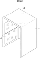
- FIG. 2 is a perspective view illustrating a control box of an air conditioner, according to an embodiment of the present disclosure.
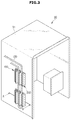
- FIG. 3 is a perspective view illustrating a control box in which a cooling unit is installed, according to an embodiment of the present disclosure.
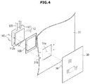
- FIG. 4 is an exploded view of a cooling unit installed in a control box, according to an embodiment of the present disclosure.
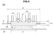
- FIG. 5 is a cross-sectional view along line A-A′ of FIG. 3 .
- FIG. 6 is a flowchart schematically illustrating a method for manufacturing a cooling unit, according to an embodiment of the present disclosure.
- FIGS. 7A-7C and 8A-8C show procedures of manufacturing a cooling unit, according to an embodiment of the present disclosure.
- FIG. 9 is a perspective view illustrating a control box in which a cooling unit is installed, according to another embodiment of the present disclosure.
- FIG. 10 is a cross-sectional view along line B-B′ of FIG. 9 .
- FIG. 11 is a perspective view illustrating a control box in which a cooling unit is installed, according to another embodiment of the present disclosure.
- FIG. 12 is a cross-sectional view along line C-C′ of FIG. 11 .
- FIGS. 13A-13C and 14A-14C show procedures of manufacturing a cooling unit, according to another embodiment of the present disclosure.
- first and second may be used to explain various components, but the components are not limited by the terms. The terms are only for the purpose of distinguishing a component from another. Thus, a first element, component, region, layer or section discussed below could be termed a second element, component, region, layer or section without departing from the teachings of the present disclosure. Descriptions shall be understood as to include any and all combinations of one or more of the associated listed items when the items are described by using the conjunctive term “ ⁇ and/or ⁇ ,” or the like.
- FIG. 1 shows a refrigeration cycle of an air conditioner that includes a cooling unit, according to an embodiment of the present disclosure.
- a refrigeration cycle of an air conditioner 1 may include a compressor 11 , a condenser 12 , an expansion valve 13 , and an evaporator 14 .
- the refrigeration cycle circulates a series of processes of compression, condensing, expansion, and evaporation, enabling heat exchange between high temperature air and low temperature refrigerants and thus supplying the cooled air into the room.
- the compressor 11 compresses a refrigerant gas 20 into a high pressure state, and discharges the resultant gas refrigerant 20 , which flows into the condenser 12 .
- the condenser 12 condenses the compressed gas refrigerant into a liquid, releasing heat to the surroundings in the condensing process. While being condensed by the condenser 12 , the refrigerant drops to a low temperature.
- the expansion valve 13 expands a high pressure and high temperature liquid refrigerant 22 condensed by the condenser 12 to a low pressure liquid refrigerant 22 .
- the evaporator 14 evaporates the refrigerant expanded by the expansion valve 13 .
- the evaporator 14 attains cooling effect by exchanging heat with an object to be cooled using latent heat of vaporization of the refrigerant, and forces the low temperature and low pressure refrigerant gas to return to the compressor 11 . Conditioned air through this refrigeration cycle may be supplied into the room.
- An outdoor unit 10 e.g., outdoor portion of the air conditioner 1 may include the compressor 11 and condenser 12 in the refrigeration cycle.
- the expansion valve 13 may be located in one of an indoor unit, e.g., indoor portion (not shown) or the outdoor unit 10 , and the evaporator 14 may be located in the indoor unit.
- a cooling unit 100 e.g. cooler may be installed between the condenser 12 and the expansion valve 13 for the refrigerant that has passed the condenser 12 to flow in thereto. While the cooling unit 100 is shown to be installed between the condenser and the expansion valve for the refrigerant that has passed the condenser to flow in thereto in an embodiment of the present disclosure, it is not limited thereto. For example, the cooling unit may be arranged between the expansion valve and the evaporator as well for the refrigerant that has passed the expansion valve to flow in thereto.
- FIG. 2 is a perspective view illustrating a control box of an air conditioner, according to an embodiment of the present disclosure
- FIG. 3 is a perspective view illustrating a control box in which a cooling unit is installed, according to an embodiment of the present disclosure.
- the outdoor unit 10 of the air conditioner may include a control box 30 .
- the control box 30 may be configured to control operation of the outdoor unit 10 of the air conditioner.
- the control box 30 may include a case 31 and electronic parts 33 .
- the case 31 may be located on an internal side of the outdoor unit 10 of the air conditioner.
- the case 31 may partition off a space where the electronic parts 33 are placed from the outdoor unit 10 of the air conditioner.
- the electronic parts 33 may be mounted in the case 31 .
- the electronic parts 33 may be mounted on one inner side wall of the case 31 .
- the electronic parts 33 may include a printed circuit board on which circuit devices are mounted.
- the electronic parts 33 may include an inverter controller, EMI, reactor, etc.
- the inverter controller may control the compressor 11 to be driven at high speed or low speed, according to conditions of the room where the air conditioner 1 is installed, or according to manipulation of the user.
- the electronic parts 33 may be heated while the air conditioner is operating. With recent advancement of technology, the electronic parts 33 are playing more roles. Accordingly, the electronic parts 33 consume more power, thereby producing more heat.
- the electronic parts 33 may be disabled or malfunction due to the heat. Furthermore, the temperature rise due to the heat produced in the electronic parts 33 may shorten life spans of the electronic parts 33 and cause degradation of the performance of the electronic parts 53 . To prevent this, the cooling unit 100 may be installed to cool the electronic parts 33 .
- the cooling unit 100 may cool a heating unit 34 , e.g. heater located inside the outdoor unit 10 of the air conditioner 1 .
- the cooling unit 100 may be arranged to come into direct contact with the heating unit 34 to exchange heat.
- the heating unit 34 may be cooled by transferring the heat of the heating unit 34 to the cooling unit 100 .
- the heating unit 34 may correspond to a heating unit 34 for the electronic parts 33 located inside the control box 30 . An example where the cooling unit 100 cools the heating unit 34 for the electronic parts 33 is described.
- the cooling unit 100 may be installed on the outer side of the control box 30 .
- the cooling unit 100 may pass through the control box 30 to come into contact with the heating unit 34 for the electronic parts 33 .
- the cooling unit 100 may be installed to be detached from the control box 30 .
- FIG. 4 is an exploded view of a cooling unit installed in a control box, according to an embodiment of the present disclosure
- FIG. 5 is a cross-sectional view along line A-A′ of FIG. 3 .
- the cooling unit 100 may be detachably coupled with the case 31 of the control box 30 through coupling members 140 .
- a via hole 31 a may be formed in the case 31 of the control box 30 for the cooling unit 100 to be installed therein to be able to come into contact.
- the via hole 31 a may be formed by boring through at least a part of the case 31 .
- the via hole 31 a may be formed to have a size corresponding to the heating unit 34 for the electronic parts 33 .
- Installers 31 b for the coupling member 140 to be installed therein to detachably install the cooling unit 100 may be formed in the case 31 .
- the installers 31 b may be formed to have the size and number to correspond to the coupling members 140 to install the cooling unit 100 .
- the cooling unit 100 may include a heat radiation member 110 , a cooling pipe 120 , and a heat transfer fin 200 .
- the heat radiation member 110 may have at least one side to come into direct contact with the heating unit 34 for the electronic parts 33 .
- the heat radiation member 110 may be installed outside of the control box 30 , and may bore through the control box 30 to come into contact with the heating unit 34 inside the control box 30 .
- the heat radiation member 110 may include a first cooling unit 111 , e.g. first cooler and a second cooling unit 112 , e.g. second cooler.
- the first and second cooling units 111 and 112 e.g., coolers of the heat radiation member 110 are members that may form a single body by being manufactured into one unit.
- the heat radiation member 110 may include at least one of aluminum (Al) and aluminum alloy.
- the first cooling unit 111 of the heat radiation member 110 may be arranged to make face-to-face contact with the heating unit 34 .
- the second cooling unit 112 may be integrally formed with the first cooling unit 111 , and may have at least one cooling pipe 120 in which the refrigerant flows arranged therein.
- the second cooling unit 112 may be located outside of the control box 30 .
- the second cooling unit 112 may be detachably combined onto the outer side of the control box 30 .
- the second cooling unit 112 may include combining holes 112 a formed for combination with the control box 30 through the combining members 140 .
- the combining holes 112 a of the second cooling unit 112 may be formed in an area not overlapping with the first cooling unit 111 .
- the second cooling unit 112 may be detachably installed at the case 31 of the control box 30 by the combining members 140 passing through the combining holes 112 a.
- the cooling pipe 120 may be inserted into the second cooling unit 112 .
- the second cooling unit 112 is formed to come into contact with the cooling pipe 120 in which the refrigerant flows to proceed heat exchange.
- the cooling pipe 120 may include at least one of copper (Cu), Aluminum (Al), and iron (Fe).
- the first cooling unit 111 may be mounted on one side of the second cooling unit 112 .
- the first cooling unit 111 may extend inward of the control box 30 from the second cooling unit 112 .
- the first cooling unit 111 may pass through the via hole 31 a of the case 31 and come into contact with the heating unit 34 .
- the length 11 of the first cooling unit 111 may be smaller than the length 12 of the second cooling unit 112 . That is, the first cooling unit 111 may be formed to be smaller in size than the second cooling unit 112 .
- the first cooling unit 111 may have the size and shape corresponding to the via hole 31 a so as to be inserted into the via hole 31 a of the case 31 .
- the first cooling unit 111 may exchanges heat with the heating unit 34 located inside of the control box 30 through direct contact.
- the first cooling unit 111 may have a lower temperature than that of the heating unit 34 due to the cooling pipe 120 coming into contact with the second cooling unit 112 . Accordingly, the heating unit 34 may be cooled by transferring heat to the first cooling unit 111 .
- the cooling pipe 120 may come into contact and thus exchange heat with the heat radiation member 110 .
- the cooling pipe 120 may extend through the inside of the heat radiation member 110 . This may increase an area of contact between the cooling pipe 120 and the heat radiation member 110 . Accordingly, the efficiency of heat exchange between the cooling pipe 120 and the heat radiation member 110 may be improved.
- the cooling pipe 120 may be formed for a refrigerant to flow therein.
- the refrigerant may include a liquid with a lower temperature than the heating unit 34 .
- the refrigerant may receive heat from the heat radiation member 110 and the heated refrigerant may circulate through the cooling pipe 120 . This may keep the heat radiation member 110 at a constant temperature.
- the cooling pipe 120 may be formed for the liquid refrigerant 21 condensed by the condenser 12 to move therein.
- the high temperature and high pressure refrigerant 20 drops to a low temperature while being condensed by the condenser 12 .
- the low temperature liquid refrigerant 21 that has passed the condenser 12 may move to the cooling unit 100 .
- the cooling unit 100 may cool the heating unit 34 with the low temperature liquid refrigerant 21 .
- the cooling pipe 120 may be formed for a low temperature and low pressure refrigerant 22 expanded by the expansion valve 13 to move therein. Although not shown, the low temperature and low pressure refrigerant 22 that has passed the expansion valve 13 may flow to the cooling unit 100 . The cooling unit 100 may cool the heating unit 34 with the low temperature and low pressure refrigerant 22 .
- the cooling unit 100 may include the heat radiation member 110 , the cooling pipe 120 , and the heat transfer fin 200 .
- the heat transfer fin 200 may be manufactured in an insert die casting method in the heat radiation member 110 .
- the heat transfer fin 200 may be arranged in the second cooling unit 112 of the heat radiation member 110 .
- the heat transfer fin 200 may be inserted into the second cooling unit 112 of the heat radiation member 110 .
- the heat transfer fin 200 may be formed of the same material as the second cooling unit 112 .
- the heat transfer fin 200 may include at least one of copper (Cu), Aluminum (Al), and iron (Fe).
- the heat transfer fin 200 may be formed integrally with the heat radiation member 110 in a way that the plurality of heat transfer fins 200 are inserted in the process of die casting manufacturing of the heat radiation member 110 .
- the heat transfer fin 200 may be placed on the other side of the second cooling unit 112 , i.e., at a position opposite to the first cooling unit 111 .
- the heat transfer fin 200 may be formed to exchange heat with air.
- the heat transfer fin 200 may be arranged on the outside of the case 31 .
- cooling may be performed through air cooling by the plurality of heat transfer fins 200 arranged in the second cooling unit 112 .
- the sealing member 130 may prevent foreign materials, such as rainwater from moving between the second cooling unit 112 and the case 31 by sealing the gap between the second cooling unit 112 and the case 31 .
- FIG. 6 is a flowchart schematically illustrating a method for manufacturing a cooling unit, according to an embodiment of the present disclosure
- FIGS. 7 and 8 show procedures of manufacturing a cooling unit, according to an embodiment of the present disclosure.
- FIG. 6 a method for manufacturing the cooling unit 100 is schematically described.
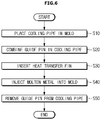
- the method for manufacturing the cooling unit 100 includes placing a cooling pipe 120 inside a die casting mold 300 , in S 10 , combining a guide pin 230 inside the cooling pipe 120 , in S 20 , inserting the heat transfer fin 200 into the die casting mold 300 , in S 30 , injecting a molten metal into the die casting mold 300 , in S 40 , and removing the guide pin 230 from the cooling pipe 120 , in S 50 .
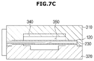
- the die casting mold 300 may include an upper mold 310 and a lower mold 320 .
- the upper mold 310 and the lower mold 320 are combined together to form a cavity 350 therein.
- a former 340 may be formed to reserve for the heat transfer fin 200 . While the former 340 is formed in the upper mold 310 in an embodiment of the present disclosure, it is not limited thereto. For example, the former 340 may be formed in the lower mold 320 as well.
- the cooling pipe 120 may be arranged such that at least a part of the cooling pipe 120 is located in the cavity 350 formed by the combination of the upper mold 310 and the lower mold 320 , in S 10 .
- Arranging the at least a part of the cooling pipe 120 in the cavity 350 to be formed integrally with the cooling unit 100 may make the cooling pipe 120 protrude to either side of the cooling unit 100 , thereby securing weldability with a counterpart pipe (not shown) for connection and thus increasing the possibility of mass production.
- the guide pin 230 is combined inside the cooling pipe 120 , in S 20 .
- the guide pin 230 may be combined in an internal fluid path 121 inside the cooling pipe 120 . This may prevent deformation and damage to the cooling pipe 120 due to a high temperature molten metal 370 being injected into the cavity 350 .
- the guide pin 230 may be formed of a metal substance.
- the guide pin 230 may be formed of a metal having a higher melting point than the cooling pipe 120 formed to have at least one of copper (Cu), aluminum (Al), and iron (Fe).
- the guide pin 230 may be formed to be inserted into the internal fluid path 121 of the cooling pipe 120 .
- the guide pin 230 may be formed to have the same or smaller cross-section than that of the internal fluid path 121 of the cooling pipe 120 .
- the heat transfer fin 200 is inserted into the former 340 of the cavity 350 , in S 30 .
- the heat transfer fin 200 is placed after the cooling pipe 120 is placed in the cavity 350 of the die casting mold 300 and the guide pin 230 is inserted to the inside 121 of the cooling pipe 120 , it is not limited thereto.
- the heat transfer fin 200 may be inserted into the cavity 350 after the step S 10 of insertion of the cooling pipe 120 .
- the heat transfer fin 200 may be inserted into the cavity 350 at the same time as in step S 10 of insertion of the cooling pipe 120 .
- the molten metal 370 is injected into the cavity 350 of a form that encloses at least a part of the cooling pipe 120 , in S 40 .
- the molten metal 370 to be injected into the cavity 350 may have temperature of about 600° C. to about 700° C.
- the molten metal 370 may include at least one of aluminum (Al) and an aluminum alloy.
- the guide pin 230 is removed from the inside of the cooling pipe 120 , in S 50 . That is, once the molten metal 370 is completely injected into the cavity 350 , the guide pin 230 may be removed.
- the guide pin 230 may be removed while the cooling pipe 120 is not deformed or damaged due to the molten metal 370 injected to the cavity 350 .
- the manufactured cooling unit 100 may be separated from the die casting mold 300 .
- the cooling unit 100 may be manufactured in a form that includes the heat radiation member 110 of a form with the cooling pipe 120 formed by solidifying the molten metal 370 inserted into the heat radiation member 110 , and the heat transfer fin 200 formed on one side of the heat radiation member 110 .
- the cooling pipe 120 since the cooling pipe 120 is formed by being inserted into the heat radiation member 110 , it may increase an area of contact between the heat radiation member 110 and the cooling pipe 120 , thereby increasing heat exchange efficiency between the refrigerant and the heat radiation member 110 .
- air cooling may be achieved by the heat transfer fin 200 arranged on the one side of the heat radiation member 110 .
- cooling is performed through the air cooling by the plurality of heat transfer fins 200 , which may, in turn, cool down the heating unit 34 , thereby increasing the cooling efficiency.
- a straight part of the streamlined cooling pipe is insert-die-casted with the heat radiation member, it is not limited thereto.
- a plurality of straight parts of the cooling pipe it is also possible for a plurality of straight parts of the cooling pipe to be insert-die-casted in multitudes.
- FIG. 9 is a perspective view illustrating a control box in which a cooling unit is installed, according to another embodiment of the present disclosure
- FIG. 10 is a cross-sectional view along line B-B′. Reference numerals not shown in FIGS. 9 and 10 may be referred to from FIGS. 1 to 8 .
- the cooling unit 100 may include a heat radiation member 110 A, a cooling pipe 120 A, and a heat transfer fin 200 A.
- the heat transfer fin 200 A may be manufactured in the insert die casting method in the heat radiation member 110 A.
- the heat transfer fin 200 A may be arranged in the second cooling unit 112 A of the heat radiation member 110 A.
- the heat transfer fin 200 A may be inserted into the second cooling unit 112 A of the heat radiation member 110 A.
- the heat transfer fin 200 A may be formed of the same material as the second cooling unit 112 A.
- the heat transfer fin 200 A may include at least one of copper (Cu), Aluminum (Al), and iron (Fe).
- the plurality of heat transfer fins 200 A may be formed in pairs of two.
- the heat transfer fin 200 A may include a first fin 201 A, a second fin 203 A, and a connector 202 A connected between the first fin 201 A and the second fin 203 A.
- the first fin 201 A and the second fin 203 A may be equally long.
- the connector 202 A is formed to connect the bottom ends of the first fin 201 A and second fin 203 A.
- the connector 202 A may be insert-die-casted in the second cooling unit 112 A of the heat radiation member 110 A.
- the heat transfer fin is insert-die-casted in the heat radiation member, it is not limited thereto.
- the heat transfer fin may be combined in the heat radiation member in an ultrasonic fusion method as well.
- the heat transfer fin 200 A may be placed on the other side of the second cooling unit 112 A, i.e., at a position opposite to the first cooling unit 111 A.
- the heat transfer fin 200 A may be arranged on the outside of the case 31 .
- the heat transfer fin 200 A is formed to exchange heat with air.
- cooling may be performed through air cooling by the plurality of heat transfer fins 200 A arranged in the second cooling unit 112 A.
- the manufacturing procedure of the cooling unit 100 A that has the heat transfer fin 200 A formed to include the second fin 203 A connected to the second fin 203 A by a connector 202 A and the cooling pipe 120 A inserted into the heat radiation member 110 A is the same for the cooling unit 110 in the embodiment as described above, so the description will be omitted herein.
- the heat transfer fins are equally long, they are not limited thereto.
- the plurality of heat transfer fins may be formed to have different lengths.
- FIG. 11 is a perspective view illustrating a control box in which a cooling unit is installed, according to another embodiment of the present disclosure
- FIG. 12 is a cross-sectional view along line C-C′ of FIG. 11
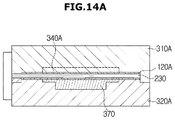
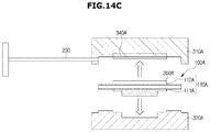
- FIGS. 13A-C and 14 A- 14 C show procedures of manufacturing a cooling unit, according to another embodiment of the present disclosure.
- Reference numerals not shown in FIGS. 11 to 14 may be referred to from FIGS. 1 to 8 .
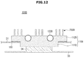
- the cooling unit 100 B may include a heat radiation member 110 B, a cooling pipe 120 B, and a heat transfer fin 200 B.
- At least a part of the cooling pipe 120 B may be inserted into the heat radiation member 110 B, and the heat transfer fin 200 B may be arranged in a part of the heat radiation member 110 B.
- the heat radiation member 110 B may include a first cooling unit 111 B and a second cooling unit 112 B.
- the first and second cooling units 111 B and 112 B of the heat radiation member 110 B are members for forming a single body unit, and the second cooling unit 112 B may be formed integrally with the first cooling unit 111 B with at least a part of the cooling pipe 120 B inserted into the single body unit.
- the at least a part of the cooling pipe 120 B may be exposed to the outside of the second cooling unit 112 B.
- the second cooling unit 112 B is formed to come into contact with the cooling pipe 120 B in which the refrigerant flows to proceed heat exchange.
- the heat transfer fin 200 B formed on one side of the second cooling unit 112 B may be located on the other side of the second cooling unit 112 B, i.e., at a position opposite to the first cooling unit 111 B.
- the heat transfer fin 200 B is formed to exchange heat with air.
- the heat transferred from the heating unit 34 may be cooled down from the outside of the heat radiation member 110 B, thereby increasing the cooling efficiency.
- the heat transfer fin 200 B may be formed integrally with a part of the second cooling unit 112 B.
- the heat transfer fin 200 B may be manufactured in a die casting method in the second cooling unit 112 B.
- the heat transfer fin 200 B may be formed of the same material as the second cooling unit 112 B.
- the heat transfer fin 200 B may include at least one of copper Cu, Aluminum Al, and iron Fe.
- the heat transfer fin 200 B may be placed on the other side of the second cooling unit 112 B, i.e., at a position opposite to the first cooling unit 111 B.
- the heat transfer fin 200 B may be arranged on the outside of the case 31 .
- the heat transfer fin 200 B is formed to exchange heat with air.
- cooling unit 100 B including the cooling pipe 120 B, a part of which is formed to be exposed to the outside of the heat radiation member 110 B, and the heat transfer fin 200 B arranged in the second cooling unit 112 B will now be described.
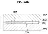
- a die casting mold 300 B includes an upper mold 310 B and a lower mold 320 B.
- the upper mold 310 B and the lower mold 320 B are combined together to form a cavity 350 B therein.
- the cavity 350 B may include a former 340 B formed to have a corresponding shape that allows the heat transfer fin 200 B to be formed and at the same time, at least a part of the cooling pipe 120 B to be exposed to the outside of the second cooling unit 112 B.
- the former 340 B is formed for the at least a part of the cooling pipe 120 B to be exposed to the heat radiation member 110 B while the heat transfer fin 200 B is formed integrally with parts of the heat radiation member 110 B
- the present disclosure is not limited thereto.
- the heat transfer fin may be manufactured in the insert die casting method in the heat radiation member by being inserted into a die casting mold.
- the cooling unit 100 B may be manufacture by inserting the cooling pipe 120 B into the die casting mold 300 B, combining the guide pin 230 in the cooling pipe 120 B, injecting a molten metal into the die casting mold 300 B, and removing the guide pin 230 from the cooling pipe 120 B.
- the guide pin 230 is combined in the cooling pipe 120 B.
- the molten metal 370 B is injected into the cavity 350 B of a form that encloses at least a part of the cooling pipe 120 B.
- the molten metal 370 B may include at least one of aluminum Al and aluminum alloy.
- the guide pin 230 is removed from the inside of the cooling pipe 120 B. That is, once the molten metal 370 B is completely injected into the cavity 350 B, the guide pin 230 may be removed.
- the guide pin 230 may be removed while the cooling pipe 120 B is not deformed or damaged due to the molten metal 370 B being injected into the cavity 350 B.
- the manufactured cooling unit 100 B may be separated from the die casting mold 300 B.
- the cooling pipe 120 B may be formed with at least a part of it inserted into the heat radiation member 110 B, it may increase an area of contact between the heat radiation member 110 B and the cooling pipe 120 B, thereby increasing heat exchange efficiency between the refrigerant flowing in the cooling pipe 120 B and the heat radiation member 110 B.
- the heat transferred from the heating unit 34 may be cooled down from the outside of the heat radiation member 110 B, thereby increasing the cooling efficiency.
- a heating unit may be efficiently cooled down.
- heat exchange efficiency may be improved by increasing an area of contact between a heat radiation member for cooling the heating unit and a cooling pipe and increasing heat transfer effects by maintaining uniformity and adhesion of the contact through direct contact.
- cooling efficiency may be increased by air cooling even if flowing of refrigerants decreases.
- Cooling efficiency may also be increased by securing a fluid path without a loss in an amount of refrigerant flow, because there is no deformation of the cooling pipe nor a loss in an area of the inside of the cooling pipe.
Landscapes
- Engineering & Computer Science (AREA)
- Microelectronics & Electronic Packaging (AREA)
- Physics & Mathematics (AREA)
- Thermal Sciences (AREA)
- Mechanical Engineering (AREA)
- General Engineering & Computer Science (AREA)
- Chemical & Material Sciences (AREA)
- Combustion & Propulsion (AREA)
- Cooling Or The Like Of Semiconductors Or Solid State Devices (AREA)
- Cooling Or The Like Of Electrical Apparatus (AREA)
Applications Claiming Priority (2)
| Application Number | Priority Date | Filing Date | Title |
|---|---|---|---|
| KR1020150147253A KR102433388B1 (ko) | 2015-10-22 | 2015-10-22 | 공기 조화기의 실외기, 이에 적용되는 냉각 유닛 및 냉각 유닛의 제조 방법 |
| KR10-2015-0147253 | 2015-10-22 |
Publications (2)
| Publication Number | Publication Date |
|---|---|
| US20170118871A1 US20170118871A1 (en) | 2017-04-27 |
| US10856442B2 true US10856442B2 (en) | 2020-12-01 |
Family
ID=58557429
Family Applications (1)
| Application Number | Title | Priority Date | Filing Date |
|---|---|---|---|
| US15/298,437 Active 2037-10-01 US10856442B2 (en) | 2015-10-22 | 2016-10-20 | Outdoor unit of air conditioner, cooling unit applied to the outdoor unit, and method for manufacturing the cooling unit |
Country Status (5)
| Country | Link |
|---|---|
| US (1) | US10856442B2 (zh) |
| EP (1) | EP3365607B1 (zh) |
| KR (1) | KR102433388B1 (zh) |
| CN (1) | CN108139087A (zh) |
| WO (1) | WO2017069485A1 (zh) |
Families Citing this family (8)
| Publication number | Priority date | Publication date | Assignee | Title |
|---|---|---|---|---|
| KR102485690B1 (ko) * | 2018-01-26 | 2023-01-06 | 삼성전자주식회사 | 공기조화기의 실외기 |
| KR102076652B1 (ko) * | 2018-03-12 | 2020-02-12 | 엘지전자 주식회사 | 공기 조화기의 실외기 |
| CN109210856A (zh) * | 2018-09-17 | 2019-01-15 | 郭增起 | 一种覆铜板生产用冷却机 |
| JP7355993B2 (ja) * | 2019-03-28 | 2023-10-04 | ダイキン工業株式会社 | 電装品箱 |
| CN109986057B (zh) * | 2019-04-23 | 2021-05-28 | 临沂大学 | 一种铝合金制成的家用空调截止阀及其制作方法 |
| EP4043809A4 (en) * | 2019-10-12 | 2024-03-06 | Qingdao Hisense Hitachi Air Conditioning Sys Co Ltd | OUTDOOR UNIT OF AN AIR CONDITIONER AND CONTROL METHOD |
| JP7309036B2 (ja) * | 2020-03-19 | 2023-07-14 | 三菱電機株式会社 | 空気調和装置の室外機 |
| CN112985147B (zh) * | 2021-04-28 | 2022-12-06 | 全球能源互联网欧洲研究院 | 一种金属相变电储热装置 |
Citations (13)
| Publication number | Priority date | Publication date | Assignee | Title |
|---|---|---|---|---|
| US6317328B1 (en) * | 2001-04-05 | 2001-11-13 | Compal Electronics, Inc. | Heat-radiating module structure |
| US20060011336A1 (en) | 2004-04-07 | 2006-01-19 | Viktor Frul | Thermal management system and computer arrangement |
| JP3920977B2 (ja) * | 1997-12-29 | 2007-05-30 | 株式会社フジクラ | ヒートシンクおよびその製造方法 |
| JP2009144995A (ja) | 2007-12-14 | 2009-07-02 | Daikin Ind Ltd | 空気調和装置の室外機 |
| KR20110020314A (ko) | 2008-07-24 | 2011-03-02 | 다이킨 고교 가부시키가이샤 | 공기조화기 |
| WO2013001829A1 (ja) * | 2011-06-29 | 2013-01-03 | パナソニック株式会社 | 冷却装置およびそれを備えた空気調和機 |
| US20130255932A1 (en) | 2012-03-30 | 2013-10-03 | Emerson Climate Technologies, Inc. | Heat sink for a condensing unit and method of using same |
| KR20140121517A (ko) | 2013-04-05 | 2014-10-16 | 삼성전자주식회사 | 공기조화기의 실외기 및 냉각장치 |
| KR20140139803A (ko) | 2013-05-28 | 2014-12-08 | 엘지전자 주식회사 | 공기 조화기 |
| KR20140144482A (ko) | 2013-06-11 | 2014-12-19 | 엘지전자 주식회사 | 공기 조화기 |
| KR20150042319A (ko) | 2013-10-10 | 2015-04-21 | 삼성전자주식회사 | 컨트롤박스 및 이를 포함하는 공기조화기의 실외기 |
| KR20150080833A (ko) | 2014-01-02 | 2015-07-10 | 엘지전자 주식회사 | 공기조화기의 실외기 |
| US20150271949A1 (en) * | 2014-03-18 | 2015-09-24 | Lg Electronics Inc. | Outdoor unit of air conditioner |
Family Cites Families (4)
| Publication number | Priority date | Publication date | Assignee | Title |
|---|---|---|---|---|
| JPS59189062A (ja) * | 1983-04-11 | 1984-10-26 | Toyo Densan Kk | エンジン用ガイドリフタ−製造法 |
| KR100978917B1 (ko) * | 2004-03-31 | 2010-08-31 | 가부시키가이샤 지교소조겐큐쇼 | 히트싱크의 제조방법 |
| KR101949294B1 (ko) * | 2012-07-24 | 2019-02-18 | 삼성전자주식회사 | 영상의 히스토그램 축적 계산 장치 및 방법 |
| KR102128584B1 (ko) * | 2013-09-16 | 2020-06-30 | 엘지전자 주식회사 | 공기 조화기 |
-
2015
- 2015-10-22 KR KR1020150147253A patent/KR102433388B1/ko active IP Right Grant
-
2016
- 2016-10-18 WO PCT/KR2016/011687 patent/WO2017069485A1/en unknown
- 2016-10-18 EP EP16857743.5A patent/EP3365607B1/en active Active
- 2016-10-18 CN CN201680059699.6A patent/CN108139087A/zh active Pending
- 2016-10-20 US US15/298,437 patent/US10856442B2/en active Active
Patent Citations (14)
| Publication number | Priority date | Publication date | Assignee | Title |
|---|---|---|---|---|
| JP3920977B2 (ja) * | 1997-12-29 | 2007-05-30 | 株式会社フジクラ | ヒートシンクおよびその製造方法 |
| US6317328B1 (en) * | 2001-04-05 | 2001-11-13 | Compal Electronics, Inc. | Heat-radiating module structure |
| US20060011336A1 (en) | 2004-04-07 | 2006-01-19 | Viktor Frul | Thermal management system and computer arrangement |
| JP2009144995A (ja) | 2007-12-14 | 2009-07-02 | Daikin Ind Ltd | 空気調和装置の室外機 |
| KR20110020314A (ko) | 2008-07-24 | 2011-03-02 | 다이킨 고교 가부시키가이샤 | 공기조화기 |
| WO2013001829A1 (ja) * | 2011-06-29 | 2013-01-03 | パナソニック株式会社 | 冷却装置およびそれを備えた空気調和機 |
| US20130255932A1 (en) | 2012-03-30 | 2013-10-03 | Emerson Climate Technologies, Inc. | Heat sink for a condensing unit and method of using same |
| CN203258933U (zh) | 2012-03-30 | 2013-10-30 | 艾默生环境优化技术有限公司 | 冷凝单元 |
| KR20140121517A (ko) | 2013-04-05 | 2014-10-16 | 삼성전자주식회사 | 공기조화기의 실외기 및 냉각장치 |
| KR20140139803A (ko) | 2013-05-28 | 2014-12-08 | 엘지전자 주식회사 | 공기 조화기 |
| KR20140144482A (ko) | 2013-06-11 | 2014-12-19 | 엘지전자 주식회사 | 공기 조화기 |
| KR20150042319A (ko) | 2013-10-10 | 2015-04-21 | 삼성전자주식회사 | 컨트롤박스 및 이를 포함하는 공기조화기의 실외기 |
| KR20150080833A (ko) | 2014-01-02 | 2015-07-10 | 엘지전자 주식회사 | 공기조화기의 실외기 |
| US20150271949A1 (en) * | 2014-03-18 | 2015-09-24 | Lg Electronics Inc. | Outdoor unit of air conditioner |
Non-Patent Citations (6)
| Title |
|---|
| Chinese Office Action dated Jul. 16, 2020 in Chinese Patent Application No. 201680059699.6. |
| Chinese Office Action dated Nov. 29, 2019 in Chinese Patent Application No. 201680059699.6. |
| English translation of JP 3920977 (Year: 2007). * |
| English translation of WO 2013/001829 (Year: 2013). * |
| Extended European Search Report dated Sep. 18, 2018 in European Patent Application No. 16857743.5. |
| International Search Report dated Dec. 14, 2016 in corresponding International Application No. PCT/KR2016/011687. |
Also Published As
| Publication number | Publication date |
|---|---|
| KR20170046967A (ko) | 2017-05-04 |
| KR102433388B1 (ko) | 2022-08-17 |
| EP3365607B1 (en) | 2023-10-18 |
| CN108139087A (zh) | 2018-06-08 |
| US20170118871A1 (en) | 2017-04-27 |
| WO2017069485A1 (en) | 2017-04-27 |
| EP3365607A4 (en) | 2018-10-17 |
| EP3365607A1 (en) | 2018-08-29 |
Similar Documents
| Publication | Publication Date | Title |
|---|---|---|
| US10856442B2 (en) | Outdoor unit of air conditioner, cooling unit applied to the outdoor unit, and method for manufacturing the cooling unit | |
| US10006646B2 (en) | Outdoor unit of air conditioner and control device for the outdoor unit | |
| KR101633781B1 (ko) | 칠러 | |
| US8316654B2 (en) | Refrigerating system and method for refrigerating | |
| KR101639814B1 (ko) | 냉장 및 냉동 복합 공조시스템 | |
| CN103597289A (zh) | 具有冷却模块的空调 | |
| US10024556B2 (en) | Outdoor unit of air conditioner, cooling unit applied thereto, and method for manufacturing cooling unit | |
| EP3073218A1 (en) | Water cooled microchannel condenser | |
| KR102485690B1 (ko) | 공기조화기의 실외기 | |
| EP2165135B1 (en) | Refrigerating system | |
| EP1843109A2 (en) | Cooling System | |
| CN209877180U (zh) | 一种双回路热管空调的自适应冷凝装置 | |
| US20140083664A1 (en) | Heat exchanger | |
| JP2008267731A (ja) | 空気調和装置 | |
| KR100327739B1 (ko) | 에어컨의 냉매관 냉각장치 | |
| JP2003254596A (ja) | 空気調和機の熱交換器の取付構造 | |
| CN107726474A (zh) | 用于空调机的室外单元 | |
| KR200179846Y1 (ko) | 히트-파이프 냉각기를 가지는 공냉식 응축기 | |
| CN212842308U (zh) | 一种复叠式冷水机组 | |
| KR101699473B1 (ko) | 냉장 및 냉동기용 열교환기 | |
| KR200143512Y1 (ko) | 공기조화기의 배관장치 | |
| WO2020235053A1 (ja) | 冷蔵庫 | |
| EP3447426A2 (en) | Double-pipe heat exchanger, heat exchange system provided with same, and method for assembling double-pipe heat exchanger | |
| KR100424295B1 (ko) | 직냉식 냉장고의 증발기 | |
| JP2019190799A5 (zh) |
Legal Events
| Date | Code | Title | Description |
|---|---|---|---|
| AS | Assignment |
Owner name: SAMSUNG ELECTRONICS CO., LTD., KOREA, REPUBLIC OF Free format text: ASSIGNMENT OF ASSIGNORS INTEREST;ASSIGNORS:CHOI, KWANG HO;CHAE, WANG BYUNG;KANG, TAE WOO;AND OTHERS;REEL/FRAME:040086/0039 Effective date: 20161021 |
|
| STPP | Information on status: patent application and granting procedure in general |
Free format text: NON FINAL ACTION MAILED |
|
| STPP | Information on status: patent application and granting procedure in general |
Free format text: RESPONSE TO NON-FINAL OFFICE ACTION ENTERED AND FORWARDED TO EXAMINER |
|
| STPP | Information on status: patent application and granting procedure in general |
Free format text: FINAL REJECTION MAILED |
|
| STPP | Information on status: patent application and granting procedure in general |
Free format text: ADVISORY ACTION MAILED |
|
| STPP | Information on status: patent application and granting procedure in general |
Free format text: DOCKETED NEW CASE - READY FOR EXAMINATION |
|
| STPP | Information on status: patent application and granting procedure in general |
Free format text: NON FINAL ACTION MAILED |
|
| STPP | Information on status: patent application and granting procedure in general |
Free format text: RESPONSE TO NON-FINAL OFFICE ACTION ENTERED AND FORWARDED TO EXAMINER |
|
| STPP | Information on status: patent application and granting procedure in general |
Free format text: RESPONSE AFTER FINAL ACTION FORWARDED TO EXAMINER |
|
| STPP | Information on status: patent application and granting procedure in general |
Free format text: ADVISORY ACTION MAILED |
|
| STPP | Information on status: patent application and granting procedure in general |
Free format text: AWAITING TC RESP, ISSUE FEE PAYMENT VERIFIED |
|
| STCF | Information on status: patent grant |
Free format text: PATENTED CASE |
|
| MAFP | Maintenance fee payment |
Free format text: PAYMENT OF MAINTENANCE FEE, 4TH YEAR, LARGE ENTITY (ORIGINAL EVENT CODE: M1551); ENTITY STATUS OF PATENT OWNER: LARGE ENTITY Year of fee payment: 4 |