US10823322B2 - Fastening device for measuring apparatuses on pipes - Google Patents
Fastening device for measuring apparatuses on pipes Download PDFInfo
- Publication number
- US10823322B2 US10823322B2 US16/299,921 US201916299921A US10823322B2 US 10823322 B2 US10823322 B2 US 10823322B2 US 201916299921 A US201916299921 A US 201916299921A US 10823322 B2 US10823322 B2 US 10823322B2
- Authority
- US
- United States
- Prior art keywords
- clamp
- housing
- pipe
- ring segments
- clamps
- Prior art date
- Legal status (The legal status is an assumption and is not a legal conclusion. Google has not performed a legal analysis and makes no representation as to the accuracy of the status listed.)
- Active
Links
- 238000005259 measurement Methods 0.000 claims description 12
- 238000003825 pressing Methods 0.000 claims description 3
- 230000008901 benefit Effects 0.000 description 2
- 238000006073 displacement reaction Methods 0.000 description 2
- 239000000243 solution Substances 0.000 description 2
- 239000000654 additive Substances 0.000 description 1
- 230000000996 additive effect Effects 0.000 description 1
- 238000005286 illumination Methods 0.000 description 1
- 230000001771 impaired effect Effects 0.000 description 1
- 238000001746 injection moulding Methods 0.000 description 1
- 238000004519 manufacturing process Methods 0.000 description 1
- 239000000463 material Substances 0.000 description 1
- 230000002787 reinforcement Effects 0.000 description 1
- 238000007789 sealing Methods 0.000 description 1
- 238000002604 ultrasonography Methods 0.000 description 1
Images


Classifications
-
- F—MECHANICAL ENGINEERING; LIGHTING; HEATING; WEAPONS; BLASTING
- F16—ENGINEERING ELEMENTS AND UNITS; GENERAL MEASURES FOR PRODUCING AND MAINTAINING EFFECTIVE FUNCTIONING OF MACHINES OR INSTALLATIONS; THERMAL INSULATION IN GENERAL
- F16B—DEVICES FOR FASTENING OR SECURING CONSTRUCTIONAL ELEMENTS OR MACHINE PARTS TOGETHER, e.g. NAILS, BOLTS, CIRCLIPS, CLAMPS, CLIPS OR WEDGES; JOINTS OR JOINTING
- F16B2/00—Friction-grip releasable fastenings
- F16B2/20—Clips, i.e. with gripping action effected solely by the inherent resistance to deformation of the material of the fastening
- F16B2/22—Clips, i.e. with gripping action effected solely by the inherent resistance to deformation of the material of the fastening of resilient material, e.g. rubbery material
-
- F—MECHANICAL ENGINEERING; LIGHTING; HEATING; WEAPONS; BLASTING
- F16—ENGINEERING ELEMENTS AND UNITS; GENERAL MEASURES FOR PRODUCING AND MAINTAINING EFFECTIVE FUNCTIONING OF MACHINES OR INSTALLATIONS; THERMAL INSULATION IN GENERAL
- F16L—PIPES; JOINTS OR FITTINGS FOR PIPES; SUPPORTS FOR PIPES, CABLES OR PROTECTIVE TUBING; MEANS FOR THERMAL INSULATION IN GENERAL
- F16L55/00—Devices or appurtenances for use in, or in connection with, pipes or pipe systems
- F16L55/07—Arrangement or mounting of devices, e.g. valves, for venting or aerating or draining
-
- B—PERFORMING OPERATIONS; TRANSPORTING
- B23—MACHINE TOOLS; METAL-WORKING NOT OTHERWISE PROVIDED FOR
- B23K—SOLDERING OR UNSOLDERING; WELDING; CLADDING OR PLATING BY SOLDERING OR WELDING; CUTTING BY APPLYING HEAT LOCALLY, e.g. FLAME CUTTING; WORKING BY LASER BEAM
- B23K11/00—Resistance welding; Severing by resistance heating
- B23K11/24—Electric supply or control circuits therefor
- B23K11/25—Monitoring devices
-
- B—PERFORMING OPERATIONS; TRANSPORTING
- B25—HAND TOOLS; PORTABLE POWER-DRIVEN TOOLS; MANIPULATORS
- B25B—TOOLS OR BENCH DEVICES NOT OTHERWISE PROVIDED FOR, FOR FASTENING, CONNECTING, DISENGAGING OR HOLDING
- B25B11/00—Work holders not covered by any preceding group in the subclass, e.g. magnetic work holders, vacuum work holders
-
- F—MECHANICAL ENGINEERING; LIGHTING; HEATING; WEAPONS; BLASTING
- F16—ENGINEERING ELEMENTS AND UNITS; GENERAL MEASURES FOR PRODUCING AND MAINTAINING EFFECTIVE FUNCTIONING OF MACHINES OR INSTALLATIONS; THERMAL INSULATION IN GENERAL
- F16L—PIPES; JOINTS OR FITTINGS FOR PIPES; SUPPORTS FOR PIPES, CABLES OR PROTECTIVE TUBING; MEANS FOR THERMAL INSULATION IN GENERAL
- F16L11/00—Hoses, i.e. flexible pipes
- F16L11/04—Hoses, i.e. flexible pipes made of rubber or flexible plastics
- F16L11/12—Hoses, i.e. flexible pipes made of rubber or flexible plastics with arrangements for particular purposes, e.g. specially profiled, with protecting layer, heated, electrically conducting
-
- F—MECHANICAL ENGINEERING; LIGHTING; HEATING; WEAPONS; BLASTING
- F16—ENGINEERING ELEMENTS AND UNITS; GENERAL MEASURES FOR PRODUCING AND MAINTAINING EFFECTIVE FUNCTIONING OF MACHINES OR INSTALLATIONS; THERMAL INSULATION IN GENERAL
- F16L—PIPES; JOINTS OR FITTINGS FOR PIPES; SUPPORTS FOR PIPES, CABLES OR PROTECTIVE TUBING; MEANS FOR THERMAL INSULATION IN GENERAL
- F16L41/00—Branching pipes; Joining pipes to walls
- F16L41/02—Branch units, e.g. made in one piece, welded, riveted
-
- G—PHYSICS
- G01—MEASURING; TESTING
- G01D—MEASURING NOT SPECIALLY ADAPTED FOR A SPECIFIC VARIABLE; ARRANGEMENTS FOR MEASURING TWO OR MORE VARIABLES NOT COVERED IN A SINGLE OTHER SUBCLASS; TARIFF METERING APPARATUS; MEASURING OR TESTING NOT OTHERWISE PROVIDED FOR
- G01D11/00—Component parts of measuring arrangements not specially adapted for a specific variable
- G01D11/24—Housings ; Casings for instruments
- G01D11/245—Housings for sensors
-
- G—PHYSICS
- G01—MEASURING; TESTING
- G01D—MEASURING NOT SPECIALLY ADAPTED FOR A SPECIFIC VARIABLE; ARRANGEMENTS FOR MEASURING TWO OR MORE VARIABLES NOT COVERED IN A SINGLE OTHER SUBCLASS; TARIFF METERING APPARATUS; MEASURING OR TESTING NOT OTHERWISE PROVIDED FOR
- G01D11/00—Component parts of measuring arrangements not specially adapted for a specific variable
- G01D11/30—Supports specially adapted for an instrument; Supports specially adapted for a set of instruments
-
- G—PHYSICS
- G01—MEASURING; TESTING
- G01N—INVESTIGATING OR ANALYSING MATERIALS BY DETERMINING THEIR CHEMICAL OR PHYSICAL PROPERTIES
- G01N21/00—Investigating or analysing materials by the use of optical means, i.e. using sub-millimetre waves, infrared, visible or ultraviolet light
- G01N21/84—Systems specially adapted for particular applications
- G01N21/88—Investigating the presence of flaws or contamination
- G01N21/95—Investigating the presence of flaws or contamination characterised by the material or shape of the object to be examined
- G01N21/952—Inspecting the exterior surface of cylindrical bodies or wires
-
- G—PHYSICS
- G01—MEASURING; TESTING
- G01N—INVESTIGATING OR ANALYSING MATERIALS BY DETERMINING THEIR CHEMICAL OR PHYSICAL PROPERTIES
- G01N33/00—Investigating or analysing materials by specific methods not covered by groups G01N1/00 - G01N31/00
- G01N33/20—Metals
- G01N33/207—Welded or soldered joints; Solderability
-
- B—PERFORMING OPERATIONS; TRANSPORTING
- B29—WORKING OF PLASTICS; WORKING OF SUBSTANCES IN A PLASTIC STATE IN GENERAL
- B29C—SHAPING OR JOINING OF PLASTICS; SHAPING OF MATERIAL IN A PLASTIC STATE, NOT OTHERWISE PROVIDED FOR; AFTER-TREATMENT OF THE SHAPED PRODUCTS, e.g. REPAIRING
- B29C65/00—Joining or sealing of preformed parts, e.g. welding of plastics materials; Apparatus therefor
- B29C65/82—Testing the joint
- B29C65/8292—Testing the joint by the use of ultrasonic, sonic or infrasonic waves
-
- B—PERFORMING OPERATIONS; TRANSPORTING
- B29—WORKING OF PLASTICS; WORKING OF SUBSTANCES IN A PLASTIC STATE IN GENERAL
- B29C—SHAPING OR JOINING OF PLASTICS; SHAPING OF MATERIAL IN A PLASTIC STATE, NOT OTHERWISE PROVIDED FOR; AFTER-TREATMENT OF THE SHAPED PRODUCTS, e.g. REPAIRING
- B29C66/00—General aspects of processes or apparatus for joining preformed parts
- B29C66/01—General aspects dealing with the joint area or with the area to be joined
- B29C66/05—Particular design of joint configurations
- B29C66/10—Particular design of joint configurations particular design of the joint cross-sections
- B29C66/11—Joint cross-sections comprising a single joint-segment, i.e. one of the parts to be joined comprising a single joint-segment in the joint cross-section
- B29C66/114—Single butt joints
- B29C66/1142—Single butt to butt joints
-
- B—PERFORMING OPERATIONS; TRANSPORTING
- B29—WORKING OF PLASTICS; WORKING OF SUBSTANCES IN A PLASTIC STATE IN GENERAL
- B29C—SHAPING OR JOINING OF PLASTICS; SHAPING OF MATERIAL IN A PLASTIC STATE, NOT OTHERWISE PROVIDED FOR; AFTER-TREATMENT OF THE SHAPED PRODUCTS, e.g. REPAIRING
- B29C66/00—General aspects of processes or apparatus for joining preformed parts
- B29C66/50—General aspects of joining tubular articles; General aspects of joining long products, i.e. bars or profiled elements; General aspects of joining single elements to tubular articles, hollow articles or bars; General aspects of joining several hollow-preforms to form hollow or tubular articles
- B29C66/51—Joining tubular articles, profiled elements or bars; Joining single elements to tubular articles, hollow articles or bars; Joining several hollow-preforms to form hollow or tubular articles
- B29C66/52—Joining tubular articles, bars or profiled elements
- B29C66/522—Joining tubular articles
- B29C66/5221—Joining tubular articles for forming coaxial connections, i.e. the tubular articles to be joined forming a zero angle relative to each other
-
- F—MECHANICAL ENGINEERING; LIGHTING; HEATING; WEAPONS; BLASTING
- F16—ENGINEERING ELEMENTS AND UNITS; GENERAL MEASURES FOR PRODUCING AND MAINTAINING EFFECTIVE FUNCTIONING OF MACHINES OR INSTALLATIONS; THERMAL INSULATION IN GENERAL
- F16L—PIPES; JOINTS OR FITTINGS FOR PIPES; SUPPORTS FOR PIPES, CABLES OR PROTECTIVE TUBING; MEANS FOR THERMAL INSULATION IN GENERAL
- F16L3/00—Supports for pipes, cables or protective tubing, e.g. hangers, holders, clamps, cleats, clips, brackets
- F16L3/08—Supports for pipes, cables or protective tubing, e.g. hangers, holders, clamps, cleats, clips, brackets substantially surrounding the pipe, cable or protective tubing
-
- G—PHYSICS
- G01—MEASURING; TESTING
- G01N—INVESTIGATING OR ANALYSING MATERIALS BY DETERMINING THEIR CHEMICAL OR PHYSICAL PROPERTIES
- G01N2201/00—Features of devices classified in G01N21/00
- G01N2201/02—Mechanical
- G01N2201/021—Special mounting in general
-
- G—PHYSICS
- G01—MEASURING; TESTING
- G01N—INVESTIGATING OR ANALYSING MATERIALS BY DETERMINING THEIR CHEMICAL OR PHYSICAL PROPERTIES
- G01N2201/00—Features of devices classified in G01N21/00
- G01N2201/06—Illumination; Optics
- G01N2201/064—Stray light conditioning
- G01N2201/0646—Light seals
-
- G—PHYSICS
- G01—MEASURING; TESTING
- G01N—INVESTIGATING OR ANALYSING MATERIALS BY DETERMINING THEIR CHEMICAL OR PHYSICAL PROPERTIES
- G01N2203/00—Investigating strength properties of solid materials by application of mechanical stress
- G01N2203/02—Details not specific for a particular testing method
- G01N2203/026—Specifications of the specimen
- G01N2203/0296—Welds
Definitions
- the invention relates to a device for fastening a measuring apparatus on pipes, in particular a butt weld seam checking measuring apparatus containing a housing for accommodating the measuring, control, and/or drive units and a clamp.
- Such devices are primarily known for ultrasound measurements with respect to a flow rate measurement, wherein in general such measuring apparatuses are fastened using simple clamping systems or a pipe clamp on the pipe, wherein devices such as these generally do not have to be rotated on the pipe circumference or moved into another position.
- WO 2011/112946 A1 discloses a device for flow rate measurement, wherein the measuring apparatus has two housings on the pipe circumference, wherein the two housings are fastened on the pipe by means of two rings.
- the clamp is designed as a ring segment, wherein the clamp is attached in the radial direction over a pipe external diameter, wherein the clamp has a pre-tension in the installed state.
- the device for fastening a measuring apparatus on pipes, in particular a butt weld seam checking measuring apparatus, has a housing for accommodating the measuring, control, and drive units. All required components for carrying out a measurement are arranged therein, in dependence on the desired measurement.
- a sensor, a circuit board, an illumination unit, a mirror, and a positioning drive are arranged during an application in the region for checking a weld seam, wherein further components or other components can also be arranged in the housing.
- the device moreover has a clamp which is used for fastening the device on the pipe.
- the clamp is clipped onto the pipe external diameter by radial pressing on, as a result of which the clamp has a wraparound angle which is greater than 180° and the ends of the clamp are thus pressed apart during the radial attachment on the pipe and press against one another again in the final position on the pipe external diameter, in particular to prevent undesired twisting with a pre-tension.
- the ring segment has a wraparound angle of greater than 180°, preferably a wraparound angle of 190-280°. It is thus ensured that the device is fixedly installed on the pipe external diameter, but is manually rotatable around the pipe external diameter or circumference and is axially displaceable along the pipe external diameter as needed.
- the housing and the clamp are preferably formed as separate parts. This is accompanied by the advantage that only one housing having the corresponding measuring apparatus is required, which can then be fastened on different pipe diameters or on the corresponding clamps, which are designed for the corresponding pipe diameters.
- the housing is thus universally designed for all clamps for the different pipe dimensions. It is advantageous if the housing and/or the clamp are each produced in the injection moulding method or by additive manufacturing.
- the clamp is preferably produced from plastic.
- the housing is also preferably produced from plastic.
- the housing is fastened by means of a quick-acting closure on the clamp, preferably by a snap closure. It is advantageous if the housing has corresponding recesses on two opposing sides, in which, for example, a cam which is arranged on the clamp engages and a tab which can be tensioned, in the opposing recess, which positions and fixes the housing on the clamp.
- the clamp preferably consists of two ring segments extending in parallel, which are connected to one another by means of at least one web.
- a recess thus results between the ring segments, which enables the device to be appropriately positioned axially, since the pipe and also the weld seam is thus visible between the ring segments.
- the recess is also used so that the access to the pipe or the weld seam is ensured to the measuring apparatus.
- housing and the clamp are connected to one another in a formfitting manner, preferably by means of the cam of the snap closure and corresponding recess which accommodates the cam and thus ensures unique positioning of the housing on the clamp.
- the clamp has markings which indicate the measurement position, these markings are preferably situated laterally on the ring segments.
- markings are indicated at a specific angle in relation to one another on the ring segment. In the case of measurements in which the device has to be rotated, it can therefore be accurately determined by which angle the device was rotated on the pipe external diameter if a marking was correspondingly provided on the pipe.
- a marking is preferably arranged at the 90° angle on the ring segment.
- FIG. 1 shows a view during the mounting of the device according to the invention
- FIG. 2 shows a view of the device according to the invention mounted on the pipe
- FIG. 3 shows a three-dimensional view of a device according to the invention
- FIG. 4 shows a view of a clamp of the device according to the invention
- FIG. 5 shows a partial view of a clamp of the device according to the invention
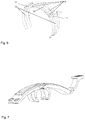
- FIG. 6 shows a three-dimensional view of a clamp of the device according to the invention
- FIG. 7 shows a three-dimensional view of a clamp of the device according to the invention for a small pipe diameter
- FIG. 8 shows a three-dimensional view of a clamp of the device according to the invention having grooves instead of pockets.
- FIG. 1 shows a device 1 according to the invention for fastening a measuring apparatus on a pipe 2 having a housing 3 in which the measuring apparatus is arranged or the units required for this purpose in accordance with the measurement to be carried out are arranged, wherein FIG. 1 shows the device 1 during the mounting. It can be seen well therein that the device 1 is pressed or clipped onto the pipe 2 in the radial direction 5 . Because the clamp 4 has a wraparound angle of greater than 180°, the ring segments 4 are spread apart as they are pressed on over the pipe diameter and then press against the pipe external circumference 2 when the device 1 is fastened on the pipe 2 .
- FIG. 2 shows the device according to the invention, which is already fastened on the pipe 2 .
- the housing 3 is fastened by means of quick-acting closure or snap closure 6 on the clamp 4 , wherein the tab 9 of the snap closure and the cam 8 engage in the recesses 7 , as can be seen in FIG. 4 , whereby the housing 3 is fastened in a formfitting manner on the clamp 4 or on the ring segment.
- the clamp 4 is preferably formed by two ring segments extending in parallel, which are connected to one another by means of at least one web 11 .
- Recesses 13 , 14 are thus formed between the ring segments, which are used in the upper region or in the region on which the housing 3 is fastened for the accessibility of the measuring apparatus to the pipe, whereby a sensor can directly or indirectly acquire the pipe external diameter or circumference or the weld seam.
- the recess in the lower region or after the two webs 11 is used so that during the attachment of the device 1 on the pipe external diameter, a rough, manual alignment in the axial direction can be performed, for example, by placing the weld seam to be checked approximately in the middle of the recess.
- edges on the ring segments which are oriented in the direction of the recesses 13 , 14 , are used as a stop or guide of the weld seam, whereby the weld seam would line up at the edges and no displacement of the clamp 4 is possible.
- the clamp 4 or the ring segments has/have a reinforcement 15 or a protrusion. This is used for light protection or shielding from the surroundings, whereby the measuring apparatuses cannot be impaired by incident light.
- the clamp 4 preferably has a marking 10 of the measuring position, which is also used for adjusting the device 1 according to the invention
- markings 10 are arranged at a specific angle in relation to one another on the clamp 4 , these enable the controlled rotation of the device 1 along the pipe circumference, whereby a measurement can always take place at a specific angle in relation to the other measurement
- a marking at an angle of 90° is preferably to be selected, whereby other positions of the markings are also conceivable.
- the housing 3 preferably has an operating unit 16 , which is kept as simple as possible, for example, by only one button which triggers different actions by various types of actuation. Moreover, it is advantageous if the operating unit has a display, preferably an LED, which indicates the operating state.
- the housing 3 preferably has a connecting unit, which enables an external controller to be attached, of course, a wireless connection to control units such as PCs is also conceivable.
- pockets 12 are arranged on the internal diameter of the clamp 4 , which are used for accommodating, for example, rubber elements, which have a higher friction resistance and thus suppress an undesired pivot of the device 1 .
- FIG. 8 A further embodiment of the clamp is shown in FIG. 8 , in which a continuous groove 19 extends along the ring segment instead of the pockets, wherein the groove 19 preferably extends in the region in which the housing 3 is fastened and is arranged in both ring segments extending in parallel.
- a sealing profile can be arranged in the groove 19 , which increases the friction resistance between pipe and clamp 4 , on the one hand, and is also used as light protection or for shielding from the environment for the sensor in the housing 3 , so that incident light does not influence the capture of the measurement data.
Applications Claiming Priority (3)
| Application Number | Priority Date | Filing Date | Title |
|---|---|---|---|
| EP18165894 | 2018-04-05 | ||
| EP18165894.9A EP3550291A1 (fr) | 2018-04-05 | 2018-04-05 | Dispositif de fixation pour appareils de mesure sur des tubes |
| EP18165894.9 | 2018-04-05 |
Publications (2)
| Publication Number | Publication Date |
|---|---|
| US20190309887A1 US20190309887A1 (en) | 2019-10-10 |
| US10823322B2 true US10823322B2 (en) | 2020-11-03 |
Family
ID=61906760
Family Applications (1)
| Application Number | Title | Priority Date | Filing Date |
|---|---|---|---|
| US16/299,921 Active US10823322B2 (en) | 2018-04-05 | 2019-03-12 | Fastening device for measuring apparatuses on pipes |
Country Status (4)
| Country | Link |
|---|---|
| US (1) | US10823322B2 (fr) |
| EP (1) | EP3550291A1 (fr) |
| KR (1) | KR20190116915A (fr) |
| CN (1) | CN110345977B (fr) |
Families Citing this family (8)
| Publication number | Priority date | Publication date | Assignee | Title |
|---|---|---|---|---|
| DK3667148T3 (da) | 2018-12-13 | 2022-11-28 | Fischer G Rohrleitungssysteme Ag | Længdekompensator |
| KR102372610B1 (ko) * | 2020-02-28 | 2022-03-10 | 지엔에스엠 주식회사 | 히터 제어 장치 및 이를 포함하는 동파 방지 시스템 |
| KR102372612B1 (ko) * | 2020-02-28 | 2022-03-10 | 지엔에스엠 주식회사 | 지지 장치 및 이를 포함하는 동파 방지 시스템 |
| DE202020001109U1 (de) | 2020-03-20 | 2020-04-09 | E+E Elektronik Ges.M.B.H. | Vorrichtung zur Überwachung der Kondensationsbildung |
| KR102594309B1 (ko) | 2020-04-20 | 2023-10-27 | (주)아그루코리아 | 용접 비드 검사 장치 |
| WO2022002892A1 (fr) * | 2020-06-29 | 2022-01-06 | Voith Patent Gmbh | Boîtier destiné à un élément rotatif |
| SE2050818A1 (en) * | 2020-07-01 | 2021-12-28 | Fumex Ab | A fastening device for a support arm |
| CN115264181B (zh) * | 2022-09-28 | 2022-12-09 | 山西中德管业有限公司 | 一种民用给排水pvc管的安装支撑装置 |
Citations (30)
| Publication number | Priority date | Publication date | Assignee | Title |
|---|---|---|---|---|
| US4454767A (en) * | 1980-03-25 | 1984-06-19 | Fuji Electric Co., Ltd. | Ultrasonic metering device |
| US5337615A (en) * | 1993-10-15 | 1994-08-16 | Jack Goss | Flow meter |
| US5615457A (en) * | 1994-07-11 | 1997-04-01 | Steinkoenig; Uwe | Spring band clamp |
| US5815892A (en) * | 1996-06-12 | 1998-10-06 | Rasmussen Gmbh | Profile clamp |
| US5819376A (en) * | 1997-12-24 | 1998-10-13 | Barnes Group Inc. | Hose clamp |
| USD457451S1 (en) * | 2001-06-14 | 2002-05-21 | Li-Chuan Chen | Clamp multimeter |
| US20030159255A1 (en) * | 2002-02-28 | 2003-08-28 | Senovich Craig A. | Clamp retention device |
| US6681642B2 (en) * | 1999-07-27 | 2004-01-27 | Surpass Industry Co. Ltd. | Ultrasonic flowmeter and manufacturing method thereof |
| US20050184722A1 (en) * | 2004-02-20 | 2005-08-25 | Gregorec James L.Jr. | Clamp meter with dual display |
| USD515953S1 (en) * | 2005-05-04 | 2006-02-28 | Appa Technology Corp. | Clamp multimeter |
| CN201397161Y (zh) | 2008-12-22 | 2010-02-03 | 珠海吉泰克燃气设备技术有限公司 | 一种涡轮式流量传感器 |
| US20100131210A1 (en) * | 2008-11-24 | 2010-05-27 | Fingerhut Martin | Method and system for non-destructive inspection of a colony of stress corrosion cracks |
| US20100148756A1 (en) * | 2007-05-18 | 2010-06-17 | Tushar Gajkumar Shah | Clamp meter with safe trigger mechanism |
| US20110015796A1 (en) * | 2009-07-17 | 2011-01-20 | Fluke Corporation | Power state coordination for portable test tools |
| WO2011112946A1 (fr) | 2010-03-11 | 2011-09-15 | Expro Meters, Inc. | Appareil et procédé destinés à détecter un écoulement de fluide dans une conduite ayant une épaisseur de paroi variable |
| US20120169324A1 (en) * | 2010-12-30 | 2012-07-05 | Fluke Corporation | Simplified jaw assembly for a clamp meter |
| US8438936B2 (en) * | 2011-06-03 | 2013-05-14 | General Electric Company | Sensor assembly including a collar for mounting sensors to a pipeline |
| US8714030B1 (en) * | 2011-09-10 | 2014-05-06 | Strain Measurement Devices, Inc. | Non-invasive tranducers for ultrasonic transit time flow meters |
| USD715169S1 (en) * | 2013-05-31 | 2014-10-14 | Li-Chuan Chen | Clamp type electrical multimeter |
| US20150160053A1 (en) * | 2013-12-06 | 2015-06-11 | Joseph Baumoel | Phase controlled variable angle ultrasonic flow meter |
| US20150267848A1 (en) * | 2014-03-21 | 2015-09-24 | Mark J. Zaharis | Crimpable separable tubing clamp |
| US20150338186A1 (en) * | 2014-05-20 | 2015-11-26 | Sig Sauer, Inc. | Adjustable buttstock clamp |
| EP2963380A1 (fr) | 2014-07-04 | 2016-01-06 | Georg Fischer Rohrleitungssysteme AG | Contrôle sans contact d'une soudure bout à bout |
| US9255641B2 (en) | 2013-07-23 | 2016-02-09 | Georg Fischer Rohrleitungssysteme Ag | Saddle for a branch connection |
| US20170074695A1 (en) * | 2014-03-04 | 2017-03-16 | Seleon Gmbh | Sensor Block, Pipe, and Production Method |
| US20170225388A1 (en) | 2016-02-09 | 2017-08-10 | Georg Fischer Rohrleitungssysteme Ag | Reflection inner ring |
| US20170361538A1 (en) | 2016-06-16 | 2017-12-21 | Georg Fischer Rohrleitungssysteme Ag | Tube end detection |
| US10035194B2 (en) | 2016-03-01 | 2018-07-31 | Georg Fischer Rohrleitungssysteme Ag | Paring and cutting tool |
| US20190111395A1 (en) * | 2016-05-05 | 2019-04-18 | Emd Millipore Corporation | Filtration Clamp With Optional Alignment Collar And Filtration System |
| US10365137B2 (en) * | 2015-01-15 | 2019-07-30 | Titan Enterprises Limited | Transit time flow meter apparatus, transducer, flow meter and method |
Family Cites Families (10)
| Publication number | Priority date | Publication date | Assignee | Title |
|---|---|---|---|---|
| GB2200206B (en) * | 1986-12-19 | 1991-02-13 | Subsea Offshore Ltd | Detection apparatus and method |
| JP2003083486A (ja) * | 2001-09-12 | 2003-03-19 | Anelva Corp | クランプ形継手およびそのセンターリング |
| DE20301398U1 (de) * | 2003-01-07 | 2003-04-03 | Oetiker Hans Maschinen | Halteklemme |
| US8882059B2 (en) * | 2010-05-04 | 2014-11-11 | Oatey Co. | Pipe clamp |
| NO334036B1 (no) * | 2010-08-06 | 2013-11-25 | Roxar Flow Measurement As | Klemme |
| AU2012337468B2 (en) * | 2011-09-22 | 2017-03-30 | Fisher & Paykel Healthcare Limited | Locking tube clip |
| AU2013205362A1 (en) * | 2013-04-22 | 2014-11-06 | Trevor Keith Dutch | Clamping device for pipes and ducting |
| CA2947811C (fr) * | 2014-06-20 | 2022-08-16 | Lake Products Limited | Attache a ajustement reglable |
| DE102014117999A1 (de) * | 2014-12-05 | 2016-06-09 | Hebotec Gmbh | Klammer |
| CN205606031U (zh) * | 2016-05-03 | 2016-09-28 | 苏州捷英特管道技术有限公司 | 带流量计安装结构的管接头 |
-
2018
- 2018-04-05 EP EP18165894.9A patent/EP3550291A1/fr active Pending
-
2019
- 2019-03-12 US US16/299,921 patent/US10823322B2/en active Active
- 2019-03-27 KR KR1020190035318A patent/KR20190116915A/ko not_active Application Discontinuation
- 2019-04-04 CN CN201910270898.7A patent/CN110345977B/zh active Active
Patent Citations (31)
| Publication number | Priority date | Publication date | Assignee | Title |
|---|---|---|---|---|
| US4454767A (en) * | 1980-03-25 | 1984-06-19 | Fuji Electric Co., Ltd. | Ultrasonic metering device |
| US5337615A (en) * | 1993-10-15 | 1994-08-16 | Jack Goss | Flow meter |
| US5615457A (en) * | 1994-07-11 | 1997-04-01 | Steinkoenig; Uwe | Spring band clamp |
| US5815892A (en) * | 1996-06-12 | 1998-10-06 | Rasmussen Gmbh | Profile clamp |
| US5819376A (en) * | 1997-12-24 | 1998-10-13 | Barnes Group Inc. | Hose clamp |
| US6681642B2 (en) * | 1999-07-27 | 2004-01-27 | Surpass Industry Co. Ltd. | Ultrasonic flowmeter and manufacturing method thereof |
| USD457451S1 (en) * | 2001-06-14 | 2002-05-21 | Li-Chuan Chen | Clamp multimeter |
| US20030159255A1 (en) * | 2002-02-28 | 2003-08-28 | Senovich Craig A. | Clamp retention device |
| US20050184722A1 (en) * | 2004-02-20 | 2005-08-25 | Gregorec James L.Jr. | Clamp meter with dual display |
| USD515953S1 (en) * | 2005-05-04 | 2006-02-28 | Appa Technology Corp. | Clamp multimeter |
| US20100148756A1 (en) * | 2007-05-18 | 2010-06-17 | Tushar Gajkumar Shah | Clamp meter with safe trigger mechanism |
| US20100131210A1 (en) * | 2008-11-24 | 2010-05-27 | Fingerhut Martin | Method and system for non-destructive inspection of a colony of stress corrosion cracks |
| CN201397161Y (zh) | 2008-12-22 | 2010-02-03 | 珠海吉泰克燃气设备技术有限公司 | 一种涡轮式流量传感器 |
| US20110015796A1 (en) * | 2009-07-17 | 2011-01-20 | Fluke Corporation | Power state coordination for portable test tools |
| WO2011112946A1 (fr) | 2010-03-11 | 2011-09-15 | Expro Meters, Inc. | Appareil et procédé destinés à détecter un écoulement de fluide dans une conduite ayant une épaisseur de paroi variable |
| US20110226063A1 (en) * | 2010-03-11 | 2011-09-22 | Expro Meters, Inc. | Apparatus and method for sensing fluid flow in a pipe with variable wall thickness |
| US20120169324A1 (en) * | 2010-12-30 | 2012-07-05 | Fluke Corporation | Simplified jaw assembly for a clamp meter |
| US8438936B2 (en) * | 2011-06-03 | 2013-05-14 | General Electric Company | Sensor assembly including a collar for mounting sensors to a pipeline |
| US8714030B1 (en) * | 2011-09-10 | 2014-05-06 | Strain Measurement Devices, Inc. | Non-invasive tranducers for ultrasonic transit time flow meters |
| USD715169S1 (en) * | 2013-05-31 | 2014-10-14 | Li-Chuan Chen | Clamp type electrical multimeter |
| US9255641B2 (en) | 2013-07-23 | 2016-02-09 | Georg Fischer Rohrleitungssysteme Ag | Saddle for a branch connection |
| US20150160053A1 (en) * | 2013-12-06 | 2015-06-11 | Joseph Baumoel | Phase controlled variable angle ultrasonic flow meter |
| US20170074695A1 (en) * | 2014-03-04 | 2017-03-16 | Seleon Gmbh | Sensor Block, Pipe, and Production Method |
| US20150267848A1 (en) * | 2014-03-21 | 2015-09-24 | Mark J. Zaharis | Crimpable separable tubing clamp |
| US20150338186A1 (en) * | 2014-05-20 | 2015-11-26 | Sig Sauer, Inc. | Adjustable buttstock clamp |
| EP2963380A1 (fr) | 2014-07-04 | 2016-01-06 | Georg Fischer Rohrleitungssysteme AG | Contrôle sans contact d'une soudure bout à bout |
| US10365137B2 (en) * | 2015-01-15 | 2019-07-30 | Titan Enterprises Limited | Transit time flow meter apparatus, transducer, flow meter and method |
| US20170225388A1 (en) | 2016-02-09 | 2017-08-10 | Georg Fischer Rohrleitungssysteme Ag | Reflection inner ring |
| US10035194B2 (en) | 2016-03-01 | 2018-07-31 | Georg Fischer Rohrleitungssysteme Ag | Paring and cutting tool |
| US20190111395A1 (en) * | 2016-05-05 | 2019-04-18 | Emd Millipore Corporation | Filtration Clamp With Optional Alignment Collar And Filtration System |
| US20170361538A1 (en) | 2016-06-16 | 2017-12-21 | Georg Fischer Rohrleitungssysteme Ag | Tube end detection |
Also Published As
| Publication number | Publication date |
|---|---|
| KR20190116915A (ko) | 2019-10-15 |
| CN110345977A (zh) | 2019-10-18 |
| CN110345977B (zh) | 2022-07-08 |
| US20190309887A1 (en) | 2019-10-10 |
| EP3550291A1 (fr) | 2019-10-09 |
Similar Documents
| Publication | Publication Date | Title |
|---|---|---|
| US10823322B2 (en) | Fastening device for measuring apparatuses on pipes | |
| KR101786646B1 (ko) | 관 내부의 도막측정장치 | |
| JP4830833B2 (ja) | 血圧計 | |
| US3664029A (en) | Dial indicator holder | |
| CA2855028A1 (fr) | Equerre combinee dotee d'une tete pivotante | |
| KR101788129B1 (ko) | 마이크로미터 세팅지그 | |
| KR101411505B1 (ko) | 곡률반경 측정장치 | |
| US20210129452A1 (en) | Weld seam testing chain | |
| CN104797945B (zh) | 用于电流传感器和/或电压传感器的紧固装置 | |
| KR20180105541A (ko) | 차량용 와이어링 클립장치 | |
| US8585301B2 (en) | Sensor-mounting bracket for camera installation procedure | |
| WO2009044745A1 (fr) | Dispositif d'essai de fatigue | |
| JP2009244004A (ja) | 非接触式変位センサ用冶具 | |
| CN111044002A (zh) | 车辆方向盘转角测试装置 | |
| KR200427425Y1 (ko) | 배관중심 측정용 타겟 | |
| KR101487657B1 (ko) | 조정관 계측용 지그장치 | |
| KR100848035B1 (ko) | 배관중심 측정용 타겟 | |
| JP2009036708A (ja) | 配管用厚さ測定装置 | |
| CN107934644B (zh) | 用于遮蔽喷涂膜加工的定位机构及遮蔽喷涂膜加工装置 | |
| KR101528325B1 (ko) | 벨트 텐션너용 스프링 고속 성형 장치 | |
| CN210051293U (zh) | 一种用于管类的三维测量设备 | |
| CN104062186A (zh) | 塑胶材料应力测试装置 | |
| CN113695986B (zh) | 弧形管道的辅助装置 | |
| WO2011160805A3 (fr) | Tête de support | |
| KR200389376Y1 (ko) | 테이핑 장치의 지그 |
Legal Events
| Date | Code | Title | Description |
|---|---|---|---|
| AS | Assignment |
Owner name: GEORG FISCHER ROHRLEITUNGSSYSTEME AG, SWITZERLAND Free format text: ASSIGNMENT OF ASSIGNORS INTEREST;ASSIGNORS:REIZ, ROBERT;ROESCH, JUERGEN;HASIFIC, EDIN;AND OTHERS;SIGNING DATES FROM 20190226 TO 20190227;REEL/FRAME:048576/0001 |
|
| FEPP | Fee payment procedure |
Free format text: ENTITY STATUS SET TO UNDISCOUNTED (ORIGINAL EVENT CODE: BIG.); ENTITY STATUS OF PATENT OWNER: LARGE ENTITY |
|
| STPP | Information on status: patent application and granting procedure in general |
Free format text: NON FINAL ACTION MAILED |
|
| STPP | Information on status: patent application and granting procedure in general |
Free format text: RESPONSE TO NON-FINAL OFFICE ACTION ENTERED AND FORWARDED TO EXAMINER |
|
| STPP | Information on status: patent application and granting procedure in general |
Free format text: FINAL REJECTION MAILED |
|
| STPP | Information on status: patent application and granting procedure in general |
Free format text: RESPONSE AFTER FINAL ACTION FORWARDED TO EXAMINER |
|
| STPP | Information on status: patent application and granting procedure in general |
Free format text: PUBLICATIONS -- ISSUE FEE PAYMENT VERIFIED |
|
| STCF | Information on status: patent grant |
Free format text: PATENTED CASE |