US10766569B2 - Bicycle control system - Google Patents
Bicycle control system Download PDFInfo
- Publication number
- US10766569B2 US10766569B2 US14/795,902 US201514795902A US10766569B2 US 10766569 B2 US10766569 B2 US 10766569B2 US 201514795902 A US201514795902 A US 201514795902A US 10766569 B2 US10766569 B2 US 10766569B2
- Authority
- US
- United States
- Prior art keywords
- controller
- control system
- signal
- operating
- bicycle
- Prior art date
- Legal status (The legal status is an assumption and is not a legal conclusion. Google has not performed a legal analysis and makes no representation as to the accuracy of the status listed.)
- Active
Links
- 230000005540 biological transmission Effects 0.000 claims description 19
- 230000004044 response Effects 0.000 claims description 18
- 230000008859 change Effects 0.000 claims description 3
- 230000006870 function Effects 0.000 description 13
- 238000010586 diagram Methods 0.000 description 6
- 230000000694 effects Effects 0.000 description 3
- 230000003287 optical effect Effects 0.000 description 2
- 239000000725 suspension Substances 0.000 description 2
- 230000002860 competitive effect Effects 0.000 description 1
- 238000010276 construction Methods 0.000 description 1
- 230000009977 dual effect Effects 0.000 description 1
- 238000012986 modification Methods 0.000 description 1
- 230000004048 modification Effects 0.000 description 1
Images


Classifications
-
- B—PERFORMING OPERATIONS; TRANSPORTING
- B62—LAND VEHICLES FOR TRAVELLING OTHERWISE THAN ON RAILS
- B62M—RIDER PROPULSION OF WHEELED VEHICLES OR SLEDGES; POWERED PROPULSION OF SLEDGES OR SINGLE-TRACK CYCLES; TRANSMISSIONS SPECIALLY ADAPTED FOR SUCH VEHICLES
- B62M9/00—Transmissions characterised by use of an endless chain, belt, or the like
- B62M9/04—Transmissions characterised by use of an endless chain, belt, or the like of changeable ratio
- B62M9/06—Transmissions characterised by use of an endless chain, belt, or the like of changeable ratio using a single chain, belt, or the like
- B62M9/10—Transmissions characterised by use of an endless chain, belt, or the like of changeable ratio using a single chain, belt, or the like involving different-sized wheels, e.g. rear sprocket chain wheels selectively engaged by the chain, belt, or the like
- B62M9/12—Transmissions characterised by use of an endless chain, belt, or the like of changeable ratio using a single chain, belt, or the like involving different-sized wheels, e.g. rear sprocket chain wheels selectively engaged by the chain, belt, or the like the chain, belt, or the like being laterally shiftable, e.g. using a rear derailleur
- B62M9/121—Rear derailleurs
- B62M9/122—Rear derailleurs electrically or fluid actuated; Controls thereof
-
- B—PERFORMING OPERATIONS; TRANSPORTING
- B62—LAND VEHICLES FOR TRAVELLING OTHERWISE THAN ON RAILS
- B62M—RIDER PROPULSION OF WHEELED VEHICLES OR SLEDGES; POWERED PROPULSION OF SLEDGES OR SINGLE-TRACK CYCLES; TRANSMISSIONS SPECIALLY ADAPTED FOR SUCH VEHICLES
- B62M25/00—Actuators for gearing speed-change mechanisms specially adapted for cycles
- B62M25/08—Actuators for gearing speed-change mechanisms specially adapted for cycles with electrical or fluid transmitting systems
-
- B—PERFORMING OPERATIONS; TRANSPORTING
- B62—LAND VEHICLES FOR TRAVELLING OTHERWISE THAN ON RAILS
- B62M—RIDER PROPULSION OF WHEELED VEHICLES OR SLEDGES; POWERED PROPULSION OF SLEDGES OR SINGLE-TRACK CYCLES; TRANSMISSIONS SPECIALLY ADAPTED FOR SUCH VEHICLES
- B62M9/00—Transmissions characterised by use of an endless chain, belt, or the like
- B62M9/04—Transmissions characterised by use of an endless chain, belt, or the like of changeable ratio
- B62M9/06—Transmissions characterised by use of an endless chain, belt, or the like of changeable ratio using a single chain, belt, or the like
- B62M9/10—Transmissions characterised by use of an endless chain, belt, or the like of changeable ratio using a single chain, belt, or the like involving different-sized wheels, e.g. rear sprocket chain wheels selectively engaged by the chain, belt, or the like
- B62M9/12—Transmissions characterised by use of an endless chain, belt, or the like of changeable ratio using a single chain, belt, or the like involving different-sized wheels, e.g. rear sprocket chain wheels selectively engaged by the chain, belt, or the like the chain, belt, or the like being laterally shiftable, e.g. using a rear derailleur
- B62M9/131—Front derailleurs
- B62M9/132—Front derailleurs electrically or fluid actuated; Controls thereof
-
- B—PERFORMING OPERATIONS; TRANSPORTING
- B62—LAND VEHICLES FOR TRAVELLING OTHERWISE THAN ON RAILS
- B62M—RIDER PROPULSION OF WHEELED VEHICLES OR SLEDGES; POWERED PROPULSION OF SLEDGES OR SINGLE-TRACK CYCLES; TRANSMISSIONS SPECIALLY ADAPTED FOR SUCH VEHICLES
- B62M25/00—Actuators for gearing speed-change mechanisms specially adapted for cycles
- B62M2025/006—Actuators for gearing speed-change mechanisms specially adapted for cycles with auxiliary shift assisting means
Definitions
- the present invention relates to a bicycle control system.
- Bicycling is becoming an increasingly more popular form of recreation as well as a means of transportation. Moreover, bicycling has become a very popular competitive sport for both amateurs and professionals. Whether the bicycle is used for recreation, transportation or competition, the bicycle industry is constantly improving the various components of the bicycle.
- One bicycle component that has been extensively redesigned is a bicycle control system.
- a bicycle control system comprises a first electrical component and a second electrical component.
- the first electrical component comprises a first base member, a first movable member, a first actuator, and a first controller.
- the first base member is configured to be attached to a bicycle body.
- the first movable member is movable relative to the first base member.
- the first actuator is configured to move the first movable member relative to the first base member.
- the first controller is configured to control the first actuator.
- the second electrical component comprises a second base member, a second movable member, a second actuator, and a second controller.
- the second base member is configured to be attached to the bicycle body.
- the second movable member is movable relative to the second base member.
- the second actuator is configured to move the second movable member relative to the second base member.
- the second controller is configured to control the second actuator.
- the first controller and the second controller are configured to wirelessly communicate.
- the first controller and the second controller are configured to wirelessly communicate, a cable electrically connecting the first electrical component and the second electrical component can be omitted from the bicycle control system.
- the bicycle control system is configured so that the first controller includes a first wireless receiver and a first wireless transmitter.
- the second controller includes a second wireless receiver and a second wireless transmitter.
- the first wireless transmitter is configured to wirelessly transmit a first signal to the second wireless receiver.
- the second wireless transmitter is configured to wirelessly transmit a second signal to the first wireless receiver.
- the bicycle control system is configured so that the first controller includes a first actuation driver configured to control the first actuator based on the second signal.
- the second controller includes a second actuation driver configured to control the second actuator based on the first signal.
- the bicycle control system further comprises an operating device configured to wirelessly transmit a first operating signal, a second operating signal, a third operating signal, and a fourth operating signal to the first controller.
- the first controller includes a third wireless receiver configured to wirelessly receive the first operating signal, the second operating signal, the third operating signal, and the fourth operating signal from the operating device.
- the bicycle control system according to the fourth aspect is configured so that the first wireless transmitter is configured to wirelessly transmit the third operating signal and the fourth operating signal to the second wireless receiver.
- the bicycle control system in accordance with the fifth aspect, it is possible to utilize the first electrical component as an intermediate communication unit for the second electrical component. This simplifies the operating device.
- the bicycle control system is configured so that the first actuation driver is configured to control the first actuator based on the second signal, the first operating signal, and the second operating signal.
- the second actuation driver is configured to control the second actuator based on the first signal, the third operating signal, and the fourth operating signal.
- the bicycle control system according to any one of the third to sixth aspects further comprises an operating device configured to wirelessly transmit a first synchro-operating signal and a second synchro-operating signal to the first controller.
- the first controller includes a third wireless receiver configured to wirelessly receive the first synchro-operating signal and the second synchro-operating signal from the operating device.
- the bicycle control system according to the seventh aspect is configured so that the first wireless transmitter is configured to wirelessly transmit the first synchro-operating signal and the second synchro-operating signal to the second wireless receiver.
- the bicycle control system is configured so that the first actuation driver is configured to control the first actuator based on the second signal, the first synchro-operating signal, and the second synchro-operating signal.
- the second actuation driver is configured to control the second actuator based on the first signal, the first synchro-operating signal, and the second synchro-operating signal.
- the bicycle control system according to any one of the third to ninth aspects further comprises an operating device configured to wirelessly transmit a first operating signal, a second operating signal, a third operating signal, and a fourth operating signal to the first controller and the second controller.
- the first controller includes a third wireless receiver configured to wirelessly receive the first operating signal and the second operating signal from the operating device.
- the second controller includes a fourth wireless receiver configured to wirelessly receive the third operating signal and the fourth operating signal from the operating device.
- the bicycle control system is configured so that the first actuation driver is configured to control the first actuator based on the second signal, the first operating signal, and the second operating signal.
- the second actuation driver is configured to control the second actuator based on the first signal, the third operating signal, and the fourth operating signal.
- the bicycle control system according to any one of the first to tenth aspects further comprises an intermediate communication device configured to wirelessly communicate with the first controller and the second controller.
- the first controller and the second controller are configured to wirelessly communicate via the intermediate communication device.
- the bicycle control system is configured so that the first controller includes a first wireless receiver and a first wireless transmitter.
- the second controller includes a second wireless receiver and a second wireless transmitter.
- the first wireless transmitter is configured to wirelessly transmit a first signal to the second wireless receiver via the intermediate communication device.
- the second wireless transmitter is configured to wirelessly transmit a second signal to the first wireless receiver via the intermediate communication device.
- the bicycle control system is configured so that the first controller includes a first actuation driver configured to control the second actuator based on the first signal.
- the second controller includes a second actuation driver configured to control the second actuator based on the first signal.
- the bicycle control system further comprises an operating device configured to output a first operating signal, a second operating signal, a third operating signal, and a fourth operating signal.
- the intermediate communication device is configured to wirelessly receive the first operating signal, the second operating signal, the third operating signal, and the fourth operating signal from the operating device.
- the first wireless receiver is configured to wirelessly receive the first operating signal and the second operating signal from the intermediate communication device.
- the second wireless receiver is configured to wirelessly receive the third operating signal and the fourth operating signal from the intermediate communication device.
- the bicycle control system is configured so that the first actuation driver is configured to control the first actuator based on the second signal, the first operating signal, and the second operating signal.
- the second actuation driver is configured to control the second actuator based on the first signal, the third operating signal, and the fourth operating signal.
- the bicycle control system according to any one of the twelfth to sixteenth aspects is configured so that the intermediate communication device has a pairing mode in which the intermediate communication device establishes a wireless communication between the intermediate communication device and each of the first controller and the second controller.
- the first controller has a pairing mode in which the first controller establishes the wireless communication between the first controller and the intermediate communication device.
- the second controller has a pairing mode in which the second controller establishes the wireless communication between the second controller and the intermediate communication device.
- the bicycle control system according to any one of the first to seventeenth aspects is configured so that the first controller has a pairing mode in which the first controller establishes a wireless communication between the first controller and the second controller.
- the second controller has a pairing mode in which the second controller establishes the wireless communication between the first controller and the second controller.
- the bicycle control system according to any one of the first to eighteenth aspects is configured so that the first electrical component comprises a front derailleur configured to shift a bicycle chain between a plurality of front sprockets.
- the second electrical component comprises a rear derailleur configured to shift the bicycle chain between a plurality of rear sprockets.
- the bicycle control system according to any one of the first to nineteenth aspects is configured so that the first controller and the second controller are configured to wirelessly communicate with each other via one of a one-way communication and a two-way communication.
- FIG. 1 is a block diagram of a bicycle control system in accordance with a first embodiment (normal mode);
- FIG. 2 is an elevational view of a first electrical component of the bicycle control system illustrated in FIG. 1 ;
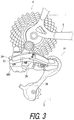
- FIG. 3 is an elevational view of a second electrical component of the bicycle control system illustrated in FIG. 1 ;
- FIG. 4 is a block diagram of the bicycle control system illustrated in FIG. 1 (synchro mode);
- FIG. 5 shows a shift table of the bicycle control system illustrated in FIG. 1 ;
- FIG. 6 is a block diagram of a bicycle control system in accordance with a second embodiment (normal mode);
- FIG. 7 is a block diagram of the bicycle control system illustrated in FIG. 6 (synchro mode);
- FIG. 8 is a block diagram of a bicycle control system in accordance with a third embodiment (normal mode).
- FIG. 9 is a block diagram of the bicycle control system illustrated in FIG. 8 (synchro mode).
- a bicycle control system 10 in accordance with a first embodiment comprises a first electrical component 12 and a second electrical component 14 .
- the first electrical component 12 comprises a front derailleur ( FIG. 2 ) configured to shift a bicycle chain 2 between a plurality of front sprockets of a front sprocket assembly 4 .
- the second electrical component 14 comprises a rear derailleur ( FIG. 3 ) configured to shift the bicycle chain 2 between a plurality of rear sprockets of a rear sprocket assembly 6 .
- the first electrical component 12 can be an electrical component other than the front derailleur, such as a bicycle suspension and a bicycle adjustable seatpost.
- the second electrical component 14 can be an electrical component other than the rear derailleur, such as a bicycle rear suspension and a bicycle adjustable seatpost.
- the following directional terms “front”, “rear”, “forward”, “rearward”, “left”, “right”, “transverse”, “upward” and “downward” as well as any other similar directional terms refer to those directions which are determined on the basis of a user (e.g., a rider) who sits on a saddle (not shown) of a bicycle (not shown) with facing a handlebar (not shown). Accordingly, these terms, as utilized to describe the bicycle control system 10 and/or other components, should be interpreted relative to the bicycle equipped with the bicycle control system 10 and/or other components as used in an upright riding position on a horizontal surface.
- the first electrical component 12 comprises a first base member 16 ( FIG. 2 ), a first movable member 18 , a first actuator 20 , and a first controller 22 .
- the first base member 16 is configured to be attached to a bicycle body 8 ( FIG. 2 ).
- the first movable member 18 is movable relative to the first base member 16 .
- the first actuator 20 is configured to move the first movable member 18 relative to the first base member 16 .
- the first controller 22 is configured to control the first actuator 20 .
- the first actuator 20 and the first controller 22 are provided in the first base member 16 .
- the first movable member 18 is contactable with the bicycle chain 2 .
- the first actuator 20 is configured to move the first movable member 18 to shift the bicycle chain 2 relative to the front sprocket assembly 4 .
- Examples of the first actuator 20 include a direct current motor and a stepper motor.
- the second electrical component 14 comprises a second base member 24 ( FIG. 3 ), a second movable member 26 , a second actuator 28 , and a second controller 30 .
- the second base member 24 is configured to be attached to the bicycle body 8 ( FIG. 3 ).
- the second movable member is movable relative to the second base member 24 .
- the second actuator 28 is configured to move the second movable member 26 relative to the second base member 24 .
- the second controller 30 configured to control the second actuator 28 .
- the second actuator 28 and the second controller 30 are provided in the second base member 24 .
- the bicycle body 8 can include a bicycle front fork and a bicycle frame.
- the second movable member 26 is contactable with the bicycle chain 2 .
- the second actuator 28 is configured to move the second movable member 26 to shift the bicycle chain 2 relative to the rear sprocket assembly 6 .
- Examples of the second actuator 28 include a direct current motor and a stepper motor.
- the first controller 22 and the second controller 30 are configured to wirelessly communicate.
- the first controller 22 and the second controller 30 are configured to wirelessly communicate with each other via one of a one-way communication and a two-way communication.
- the first controller 22 and the second controller 30 are configured to wirelessly communicate with each other via the two-way communication.
- the first controller 22 includes a first wireless receiver WR 1 and a first wireless transmitter WT 1 .
- the second controller 30 includes a second wireless receiver WR 2 and a second wireless transmitter WT 2 .
- the first wireless transmitter WT 1 is configured to wirelessly transmit a first signal S 1 to the second wireless receiver WR 2 .
- the second wireless transmitter WT 2 is configured to wirelessly transmit a second signal S 2 to the first wireless receiver WR 1 .
- the first signal S 1 includes first information relating to the first electrical component 12 .
- the second signal S 2 includes second information relating to the second electrical component 14 .
- the first controller 22 includes a first signal controller SC 1 configured to control the first wireless receiver WR 1 and the first wireless transmitter WT 1 based on input signals such as the second signal S 2 .
- the second controller 30 includes a second signal controller SC 2 configured to control the second wireless receiver WR 2 and the second wireless transmitter WT 2 based on input signals such as the first signal S 1 .
- the first controller 22 includes a first processor PR 1 and a first memory M 1 .
- the first processor PR 1 includes a central processing unit (CPU).
- the first memory M 1 includes a read only memory (ROM) and a random access memory (RAM).
- ROM read only memory
- RAM random access memory
- a program stored in the first memory M 1 is read into the first processor PR 1 , and thereby several functions of the first controller 22 are performed.
- the first controller 22 is programmed to perform functions of the first wireless receiver WR 1 , the first wireless transmitter WT 1 , and the first signal controller SC 1 .
- the second controller 30 includes a second processor PR 2 and a second memory M 2 .
- the second processor PR 2 includes a CPU.
- the second memory M 2 includes a ROM and a RAM.
- a program stored in the second memory M 2 is read into the second processor PR 2 , and thereby several functions of the second controller 30 are performed.
- the second controller 30 is programmed to perform functions of the second wireless receiver WR 2 , the second wireless transmitter WT 2 , and the second signal controller SC 2 .
- the first controller 22 includes a first actuation driver 32 and a first position sensor 34 .
- the first actuation driver 32 is configured to control the first actuator 20 based on the second signal S 2 .
- the first actuation driver 32 and the first position sensor 34 are electrically connected to the first controller 22 .
- the first position sensor 34 is configured to sense a current position of the first movable member 18 relative to the first base member 16 ( FIG. 2 ) via the first actuator 20 for determining a current gear position of the first electrical component 12 .
- the first position sensor 34 examples include a contact rotational position sensor such as a potentiometer, and a non-contact rotational position sensor such as an optical sensor (e.g., a rotary encoder) and a magnetic sensor (e.g., a hall sensor).
- a contact rotational position sensor such as a potentiometer
- a non-contact rotational position sensor such as an optical sensor (e.g., a rotary encoder) and a magnetic sensor (e.g., a hall sensor).
- the current position of the first actuator 20 is stored in the first memory M 1 .
- the second controller 30 includes a second actuation driver 36 and a second position sensor 38 .
- the second actuation driver 36 is configured to control the second actuator 28 based on the first signal S 1 .
- the second actuation driver 36 and the second position sensor 38 are electrically connected to the second controller 30 .
- the second position sensor 38 is configured to sense a current position of the second movable member 26 relative to the second base member 24 ( FIG. 3 ) via the second actuator 28 for determining a current gear position of the second electrical component 14 .
- Examples of the second position sensor 38 include a contact rotational position sensor such as a potentiometer, and a non-contact rotational position sensor such as an optical sensor (e.g., a rotary encoder) and a magnetic sensor (e.g., a hall sensor).
- the current position of the second actuator 28 is stored in the second memory M 2 .
- the first electrical component 12 includes a first battery BT 1 configured to supply electric power to the first actuator 20 , the first controller 22 , the first actuation driver 32 , and the first position sensor 34 .
- the first battery BT 1 is electrically connected to the first actuator 20 , the first controller 22 , the first actuation driver 32 , and the first position sensor 34 .
- the second electrical component 14 includes a second battery BT 2 configured to supply electric power to the second actuator 28 , the second controller 30 , the second actuation driver 36 , and the second position sensor 38 .
- the second battery BT 2 is electrically connected to the second actuator 28 , the second controller 30 , the second actuation driver 36 , and the second position sensor 38 .
- the first battery BT 1 and the second battery BT 2 can be omitted from the first electrical component 12 and the second electrical component 14 , and can be attached to the bicycle body 8 and electrically connected to the first electrical component 12 and the second electrical component 14 via an electrical wire. Additionally, in such case, the second battery BT 2 can be integral with the first battery BT 1 and provided as one battery.
- the bicycle control system 10 further comprises an operating device 40 .
- the operating device 40 is configured to wirelessly transmit a first operating signal OS 1 , a second operating signal OS 2 , a third operating signal OS 3 , and a fourth operating signal OS 4 to the first controller 22 .
- the operating device 40 is mounted to a handlebar. While the operating device 40 is illustrated as a single device in FIG. 1 , the operating device 40 can be separate units.
- the first operating signal OS 1 corresponds to an upshifting signal to upshift the first electrical component 12 .
- the second operating signal OS 2 corresponds to a downshifting signal to downshift the first electrical component 12 .
- the third operating signal OS 3 corresponds to an upshifting signal to upshift the first electrical component 12 .
- the fourth operating signal OS 4 corresponds to a downshifting signal to downshift the first electrical component 12 .
- upshift refers to changing into a higher gear in the bicycle control system 10 .
- downshift refers to changing into a lower gear in the bicycle control system 10 .
- upshifting occurs when the bicycle chain 2 ( FIG. 1 ) is shifted by the first electrical component 12 from a smaller sprocket to a neighboring larger sprocket in the front sprocket assembly 4 .
- the larger sprocket has a total number of teeth larger than a total number of teeth of the neighboring smaller sprocket.
- Downshifting occurs when the bicycle chain 2 is shifted by the second electrical component 14 from a small sprocket to a neighboring larger sprocket in the rear sprocket assembly 6 .
- the smaller sprocket has a total number of teeth smaller than a total number of teeth of the neighboring larger sprocket.
- the operating device 40 includes a first shift switch US 1 , a second shift switch DS 1 , a third shift switch US 2 , and a fourth shift switch DS 2 .
- the first shift switch US 1 is configured to generate the first operating signal OS 1 in response to an upshift input operation from a user.
- the second shift switch DS 1 is configured to generate the second operating signal OS 2 in response to a downshift input operation from the user.
- the third shift switch US 2 is configured to generate the third operating signal OS 3 in response to an upshift input operation from the user.
- the fourth shift switch DS 2 is configured to generate the fourth operating signal OS 4 in response to a downshift input operation from the user.
- the operating device 40 includes an operating controller 41 wirelessly transmit the first to fourth operating signals OS 1 to OS 4 to the first controller 22 .
- the operating controller 41 includes a third wireless transmitter WT 3 and a third signal controller SC 3 .
- the third wireless transmitter is configured to wirelessly transmit the first to fourth operating signals OS 1 to OS 4 to the first controller 22 .
- the third signal controller SC 3 is configured to control the third wireless transmitter WT 3 based on the first to fourth operating signals OS 1 to OS 4 .
- the operating controller 41 includes a third processor PR 3 and a third memory M 3 .
- the third processor PR 3 includes a CPU.
- the third memory M 3 includes a ROM and a RAM.
- a program stored in the third memory M 3 is read into the third processor PR 3 , and thereby several functions of the operating controller 41 are performed.
- the operating controller 41 is programmed to perform functions of the third wireless transmitter WT 3 and the third signal controller SC 3 .
- the operating device 40 includes a third battery BT 3 configured to supply electric power to the first to fourth shift switches US 1 , DS 1 , US 2 and DS 2 and the operating controller 41 .
- the third battery BT 3 is electrically connected to the first to fourth shift switches US 1 , DS 1 , US 2 and DS 2 and the operating controller 41 .
- the operating controller 41 is electrically connected to the first to fourth shift switches US 1 , DS 1 , US 2 and DS 2 .
- the third battery BT 3 can be omitted from the operating device 40 and can be attached to the handlebar and electrically connected to the operating device 40 via an electrical wire.
- the third battery BT 3 can be omitted from the operating device 40 , and the operating device 40 can include a power-generating unit configured to generate electrical power by movement of the first to fourth shift switches US 1 , DS 1 , US 2 and DS 2 .
- the bicycle control system 10 has a normal mode and a synchro mode.
- the first electrical component 12 and the second electrical component 14 are independently controlled based on the shift signals from the operating device 40 without using a transmission route R 1 ( FIG. 5 ).
- the synchro mode the first electrical component 12 and the second electrical component 14 are controlled in accordance with the transmission route R 1 in response to a single shift signal from the operating device 40 .
- the first controller 22 is configured to store the transmission route R 1 in the first memory M 1 .
- the second controller 30 is configured to store the transmission route R 1 in the second memory M 2 .
- the first controller 22 includes a third wireless receiver WR 3 .
- the third wireless receiver WR 3 is configured to wirelessly receive the first operating signal OS 1 , the second operating signal OS 2 , the third operating signal OS 3 , and the fourth operating signal OS 4 from the operating device 40 (in this embodiment, from the third wireless transmitter WT 3 ).
- the first wireless transmitter WT 1 is configured to wirelessly transmit the third operating signal OS 3 and the fourth operating signal OS 4 to the second wireless receiver WR 2 .
- the third operating signal OS 3 and the fourth operating signal OS 4 are transmitted from the operating device 40 to the second controller 30 via the first controller 22 .
- the first wireless receiver WR 1 and the third wireless receiver WR 3 can be provide as one wireless receiver.
- the first wireless receiver WR 1 , the first wireless transmitter WT 1 , and the third wireless receiver WR 3 can be omitted from the first electrical component 12 , and can be attached to the bicycle body 8 and electrically connected to the first electrical component 12 via an electrical wire.
- the second wireless receiver WR 2 and the second wireless transmitter WT 2 can be omitted from the second electrical component 14 and can be attached to the bicycle body 8 and electrically connected to the second electrical component 14 via an electrical wire.
- the first actuation driver 32 is configured to control the first actuator 20 based on the second signal S 2 , the first operating signal OS 1 , and the second operating signal OS 2 .
- the second actuation driver 36 is configured to control the second actuator 28 based on the first signal S 1 , the third operating signal OS 3 , and the fourth operating signal OS 4 .
- the operating device 40 in the synchro mode, is configured to wirelessly transmit a first synchro-operating signal SS 1 and a second synchro-operating signal SS 2 to the first controller 22 .
- the third wireless receiver WR 3 is configured to wirelessly receive the first synchro-operating signal SS 1 and the second synchro-operating signal SS 2 from the operating device 40 .
- the first wireless transmitter WT 1 is configured to wirelessly transmit the first synchro-operating signal SS 1 and the second synchro-operating signal SS 2 to the second wireless receiver WR 2 .
- the first synchro-operating signal SS 1 and the second synchro-operating signal SS 2 are transmitted from the operating device 40 to the second controller 30 via the first controller 22 .
- the first synchro-operating signal SS 1 corresponds to the first operating signal OS 1 and can also be referred to as the first operating signal OS 1 .
- the second synchro-operating signal SS 2 corresponds to the second operating signal OS 2 and can also be referred to as the second operating signal OS 2 .
- the third operating signal OS 3 and the fourth operating signal OS 4 are not used for changing gears in the synchro mode.
- the first synchro-operating signal SS 1 can correspond to one of the third operating signal OS 3 and the fourth operating signal OS 4 .
- the second synchro-operating signal SS 2 can correspond to the other of the third operating signal OS 3 and the fourth operating signal OS 4 .
- the operating device 40 can be omitted from the bicycle control system 10 if needed and/or desired.
- the first controller 22 and the second controller 30 can be configured to automatically control the first electrical component 12 and the second electrical component 14 without input signals such as the first to fourth operating signals OS 1 to OS 4 .
- At least one of the first to fourth shift switches US 1 , DS 1 , US 2 , and DS 2 can be omitted from the operating device 40 .
- the third shift switch US 2 and the fourth shift switch DS 2 can be omitted from the operating device 40 in a case where the bicycle control system 10 has only the synchro mode.
- FIG. 5 shows a shift table including gear ratios, a total number of teeth of each front sprocket of the front sprocket assembly 4 (“FS”), and a total number of teeth of each rear sprocket of the rear sprocket assembly 6 (“RS”).
- the first controller 22 of the first electrical component 12 is configured to store the shift table for the bicycle control system 10 .
- the first electrical component 12 has low and top gears as the gear position.
- the second electrical component 14 has first to eleventh gears as the gear position.
- the transmission route R 1 includes synchro-shift points which are each circled with a single circle.
- the first controller 22 and the second controller 30 respectively synchronously control the first actuator 20 and the second actuator 28 via the first actuation driver 32 and the second actuation driver 36 to change gears at the gear positions corresponding to the synchro-shift point in response to a single shift signal such as the first synchro-operating signal or the second synchro-operating signal.
- the transmission route R 1 is used for both upshifting and downshifting.
- each of the first controller and the second controller can be configured to store an upshift route for upshifting and a downshift route, which is different from the upshift route, for downshifting.
- first to seventh gears of the first electrical component 12 are used for low gear of the second electrical component 14 .
- Sixth to eleventh gears of the first electrical component 12 are used for top gear of the second electrical component 14 .
- thirteen gear positions on the transmission route R 1 can be used in the synchro mode.
- the first actuation driver 32 is configured to control the first actuator 20 based on the second signal S 2 , the first synchro-operating signal SS 1 , and the second synchro-operating signal SS 2 .
- the second actuation driver 36 is configured to control the second actuator 28 based on the first signal S 1 , the first synchro-operating signal SS 1 , and the second synchro-operating signal SS 2 .
- the first controller 22 is configured to wirelessly transmit, as the first signal S 1 , the current gear position of the first electrical component 12 to the second controller 30 .
- the second controller 30 is configured to wirelessly transmit, as the second signal S 2 , the current gear position of the second electrical component 14 to the first controller 22 .
- the first controller 22 can be configured to wirelessly transmit, as the first signal S 1 , a completion signal indicative of completion of shifting the bicycle chain 2 to the second controller 30 .
- the second controller 30 can be configured to wirelessly transmit, as the second signal S 2 , a completion signal indicative of completion of shifting the bicycle chain 2 to the first controller 22 .
- the bicycle control system 10 further comprises a mode selector 42 configured to allow the user to select a shifting mode among the normal mode and the synchro mode.
- Each of the first controller 22 and the second controller 30 is configured to set the shifting mode selected via the mode selector 42 .
- the mode selector 42 is mounted to the operating device 40 and electrically connected to the operating controller 41 .
- the operating controller 41 is configured to wirelessly transmit a mode signal MS 1 generated in the mode selector 42 to the first controller 22 .
- the first controller 22 is configured to wirelessly transmit the mode signal MS 1 to the second controller 30 .
- the first controller 22 switches the first electrical component 12 between the normal mode and the synchro mode based on the mode signal MS 1 .
- the second controller 30 switches the second electrical component 14 between the normal mode and the synchro mode based on the mode signal MS 1 .
- the bicycle control system 10 has the normal mode and the synchro mode
- one of the normal mode and the synchro mode can be omitted from the bicycle control system 10 if needed and/or desired.
- the mode selector 42 can be omitted from the bicycle control system 10 .
- the first controller 22 is configured to control the first actuator 20 via the first actuation controller 32 to upshift in response to the first operating signal OS 1 regardless of the transmission route R 1 .
- the first controller 22 is configured to control the first actuator 20 via the first actuation controller 32 to downshift in response to the second operating signal OS 2 regardless of the transmission route R 1 .
- the second controller 30 is configured to control the second actuator 28 via the second actuation driver 36 to upshift in response to the third operating signal OS 3 regardless of the transmission route R 1 .
- the second controller 30 is configured to control the second actuator 28 via the second actuation driver 36 to downshift in response to the fourth operating signal OS 4 regardless of the transmission route R 1 . Namely, it is possible to use twenty two gear positions in the bicycle control system 10 .
- the first controller 22 is configured to control the first actuator 20 via the first actuation driver 32 in accordance with the transmission route R 1 in response to the first and second synchro-operating signals SS 1 and SS 2 (in this embodiment, the first and second operating signals OS 1 and OS 2 ).
- the second controller 30 is configured to control the second actuator 28 via the second actuation driver 36 in accordance with the transmission route R 1 in response to the first and second synchro-operating signals SS 1 and SS 2 (in this embodiment, the first and second operating signals OS 1 and OS 2 ).
- the first electrical component 12 is configured to adjust an initial position of the first movable member 18 based on the current gear position of the second electrical component 14 .
- the second controller 30 is configured to wirelessly transmit, as the second signal S 2 , a current gear position of the second electrical component 14 to the first controller 22 .
- the second signal controller SC 2 is configured to calculate the current gear position of the second electrical component 14 based on the current position of the second movable member 26 .
- the first signal controller SC 1 is configured to calculate a preferable initial position of the first movable member 18 to avoid interference between the first movable member 18 and the bicycle chain 2 .
- the first controller 22 is configured to control the first actuator 20 via the first actuation driver 32 so that the first movable member 18 is positioned at the preferable initial position.
- the second controller 30 wirelessly transmits the new current gear position to the first controller 22 .
- the first controller 22 controls the first actuator 20 via the first actuation driver 32 to change the initial position to the preferable initial position after the first electrical component 12 and the second electrical component 14 complete changing gears. This can prevent the interference between the first movable member 18 and the bicycle chain 2 when the first movable member 18 is positioned at the initial position.
- the first controller 22 has a pairing mode in which the first controller 22 establishes a wireless communication between the first controller 22 and the second controller 30 .
- the second controller 30 has a pairing mode in which the second controller 30 establishes the wireless communication between the first controller 22 and the second controller 30 .
- the first electrical component 12 includes a first pairing mode switch SW 1 configured to bring the first controller 22 into a pairing mode in response to a mode switching operation from the user.
- the first pairing mode switch SW 1 is configured to receive the mode switching operation from the user to bring the first controller 22 into the pairing mode.
- the first controller 22 enters the pairing mode when the first pairing mode switch SW 1 is operated by the user.
- the second electrical component 14 includes a second pairing mode switch SW 2 configured to bring the second controller 30 into a pairing mode in response to a mode switching operation from the user.
- the second pairing mode switch SW 2 is configured to receive the mode switching operation from the user to bring the second controller 30 into the pairing mode.
- the second controller 30 enters the pairing mode when the second pairing mode switch SW 2 is operated by the user.
- the first controller 22 identifies the second electrical component 14 based on the pairing demand signal received by the first wireless receiver WR 1 .
- the first controller 22 controls the first wireless receiver WR 1 to scan wireless signals on specific channels.
- the first signal controller SC 1 controls the first wireless transmitter WT 1 to repeatedly transmit a wireless signal indicating the identifying information of the second electrical component 14 during the pairing mode.
- the first wireless receiver WR 1 receives the wireless signal indicating the identifying information of the second electrical component 14 .
- the first controller 22 is configured to store reference ID data and reference signal patterns corresponding to the reference ID data in the first memory M 1 .
- the reference ID data indicate device IDs of the operating device 40 which are configured to establish a wireless communication with the first electrical component 12 .
- the first controller 22 is configured to compare the identifying information of the operating device 40 with the reference ID data.
- the first controller 22 is configured to determine, among the reference signal patterns, a target signal pattern corresponding to the identifying information received by the first wireless receiver WR 1 .
- the first controller 22 is configured to temporarily store the identifying information of the operating device 40 and the determined target signal pattern in the first memory M 1 .
- the first controller 22 is configured to interpret, using the target signal pattern, the wireless signals transmitted from the first wireless transmitter WT 1 as separate signals from wireless signals transmitted from other devices. Thus, the first controller 22 establishes the wireless communication with the second controller 30 .
- the pairing mode is finished in the first electrical component 12 when the first pairing mode switch SW 1 is operated in the pairing mode.
- the second controller 30 identifies the first electrical component 12 based on the pairing demand signal received by the second wireless receiver WR 2 .
- the second controller 30 controls the second wireless receiver WR 2 to scan wireless signals on specific channels.
- the second signal controller SC 2 controls the second wireless transmitter WT 2 to repeatedly transmit a wireless signal indicating the identifying information of the first electrical component 12 during the pairing mode.
- the second wireless receiver WR 2 receives the wireless signal indicating the identifying information of the first electrical component 12 .
- the second controller 30 is configured to store reference ID data and reference signal patterns corresponding to the reference ID data in the second memory M 2 .
- the reference ID data indicate device IDs of the operating device 40 which are configured to establish a wireless communication with the second electrical component 14 .
- the second controller 30 is configured to compare the identifying information of the operating device 40 with the reference ID data.
- the second controller 30 is configured to determine, among the reference signal patterns, a target signal pattern corresponding to the identifying information received by the second wireless receiver WR 2 .
- the second controller 30 is configured to temporarily store the identifying information of the operating device 40 and the determined target signal pattern in the second memory M 2 .
- the second controller 30 is configured to interpret, using the target signal pattern, the wireless signals transmitted from the second wireless transmitter WT 2 as separate signals from wireless signals transmitted from other devices. Thus, the second controller 30 establishes the wireless communication with the first controller 22 .
- the pairing mode is finished in the second electrical component 14 when the first pairing mode switch SW 1 is operated in the pairing mode.
- the first controller 22 and the second controller 30 are configured to wirelessly communicate with each other via the two-way communication.
- the first controller 22 and the second controller 30 can be configured to wirelessly communicate with each other via the one-way communication.
- the first controller 22 and the second controller 30 are preferably configured to wirelessly communicate with each other via the one-way communication.
- the first controller 22 and the second controller 30 can be configured to wirelessly communicate with each other via the one-way communication.
- the bicycle control system 10 comprises the operating device 40 , it is possible to operate the first electrical component 12 and the second electrical component 14 via the operating member.
- the first wireless transmitter WT 1 is configured to wirelessly transmit the third operating signal OS 3 and the fourth operating signal OS 4 to the second wireless receiver WR 2 . Accordingly, it is possible to utilize the first electrical component 12 as an intermediate repeater for the second electrical component 14 . This can simplify the bicycle control system 10 .
- each of the first controller 22 and the second controller 30 have the pairing mode, it is possible to establish the wireless communication between the first controller 22 and the second controller 30 without crosstalk.
- a bicycle control system 210 in accordance with a second embodiment will be described below referring to FIGS. 6 and 7 .
- the bicycle control system 210 has the same configuration as the bicycle control system 10 except for the second controller 30 and the operating controller 241 .
- elements having substantially the same function as those in the first embodiment will be numbered the same here, and will not be described and/or illustrated again in detail here for the sake of brevity.
- the second electrical component 14 comprises a second controller 230 .
- the second controller 230 has substantially the same configuration as that of the second controller 30 in the first embodiment. Unlike the second controller 30 , however, the second controller 230 includes a fourth wireless receiver WR 4 configured to wirelessly receive the third operating signal OS 3 and the fourth operating signal OS 4 from the operating device 40 .
- the second wireless receiver WR 2 and the fourth wireless receiver WR 4 can be provide as one wireless receiver.
- the second controller 230 is configured to wirelessly receive the third operating signal OS 3 and the fourth operating signal OS 4 from the operating device 240 without via the first controller 22 .
- the operating device 40 includes an operating controller 241 .
- the operating controller 241 has substantially the same configuration as that of the operating controller 41 in the first embodiment.
- the operating controller 241 includes a fourth wireless transmitter WT 4 configured to wirelessly transmit the third operating signal OS 3 and the fourth operating signal OS 4 to the fourth wireless receiver WR 4 of the second controller 230 .
- the mode signal MS 1 is transmitted from the fourth wireless transmitter WT 4 to the fourth wireless receiver WR 4 .
- the fourth wireless receiver WR 4 is configured to wirelessly receive the first synchro-operating signal SS 1 (in this embodiment, the first operating signal OS 1 ) and the second synchro-operating signal SS 2 (in this embodiment, the second operating signal OS 2 ) from the fourth wireless transmitter WT 4 of the operating device 40 .
- a bicycle control system 310 in accordance with a third embodiment will be described below referring to FIGS. 8 and 9 .
- the bicycle control system 310 has the same configuration as the bicycle control system 10 except for an intermediate communication device.
- elements having substantially the same function as those in the above embodiments will be numbered the same here, and will not be described and/or illustrated again in detail here for the sake of brevity.
- the bicycle control system 310 further comprises an intermediate communication device 350 configured to wirelessly communicate with the first controller 22 and the second controller 30 .
- the first controller 22 and the second controller 30 are configured to wirelessly communicate via the intermediate communication device 350 .
- the first wireless transmitter WT 1 is configured to wirelessly transmit the first signal S 1 to the second wireless receiver WR 2 via the intermediate communication device 350 .
- the second wireless transmitter WT 2 is configured to wirelessly transmit the second signal S 2 to the first wireless receiver WR 1 via the intermediate communication device 350 .
- the intermediate communication device 350 is configured to wirelessly receive the first operating signal OS 1 , the second operating signal OS 2 , the third operating signal OS 3 , and the fourth operating signal OS 4 from the operating device 40 .
- the first wireless receiver WR 1 is configured to wirelessly receive the first operating signal OS 1 and the second operating signal OS 2 from the intermediate communication device 350 .
- the second wireless receiver WR 2 is configured to wirelessly receive the third operating signal OS 3 and the fourth operating signal OS 4 from the intermediate communication device 350 .
- the third wireless receiver WR 3 is omitted from the first controller 22 .
- the intermediate communication device 350 includes a third controller 352 configured to wirelessly communicate with the first electrical component 12 , the second electrical component 14 , and the operating device 40 .
- the third controller 352 includes a fifth wireless receiver WR 5 , a fifth wireless transmitter WT 5 , a sixth wireless transmitter WT 6 , and a fourth signal controller SC 4 .
- the fourth signal controller SC 4 is configured to control the fifth wireless receiver WR 5 , the fifth wireless transmitter WT 5 , and the sixth wireless transmitter WT 6 based on input signals from the first electrical component 12 , the second electrical component 14 , and the operating device 40 .
- the intermediate communication device 350 includes a fourth battery BT 4 configured to supply electric power to the third controller 352 .
- the fourth battery BT 4 is electrically connected to the third controller 352 .
- the intermediate communication device 350 can be mounted on the bicycle body 8 .
- the fourth battery BT 4 can be omitted from the intermediate communication device 350 , and can be attached to the bicycle body 8 and electrically connected to the intermediate communication device 350 via an electrical wire.
- the fifth wireless receiver WR 5 is configured to wirelessly receive the first to fourth operating signals OS 1 to OS 4 from the third wireless transmitter WT 3 of the operating device 40 .
- the fifth wireless transmitter WT 5 is configured to wirelessly transmit the first operating signal OS 1 and the second operating signal OS 2 to the first wireless receiver WR 1 .
- the sixth wireless transmitter WT 6 is configured to wirelessly transmit the third operating signal OS 3 and the fourth operating signal OS 4 to the second wireless receiver WR 2 .
- the fifth wireless transmitter WT 5 and the sixth wireless transmitter WT 6 are controlled by the fourth signal controller SC 4 .
- the first actuation driver 32 is configured to control the first actuator based on the second signal S 2 , the first operating signal OS 1 , and the second operating signal OS 2 .
- the second actuation driver 36 is configured to control the second actuator 28 based on the first signal S 1 , the third operating signal OS 3 , and the fourth operating signal OS 4 .
- the fifth wireless receiver WR 5 is configured to wirelessly receive the first synchro-operating signal SS 1 (in this embodiment, the first operating signal OS 1 ) and the second synchro-operating signal SS 2 (in this embodiment, the second operating signal OS 2 ) from the third wireless transmitter WT 3 .
- the fifth wireless transmitter WT 5 is configured to wirelessly transmit the first synchro-operating signal SS 1 and the second synchro-operating signal SS 2 to the first wireless receiver WR 1 .
- the sixth wireless transmitter WT 6 is configured to wirelessly transmit the first synchro-operating signal SS 1 and the second synchro-operating signal SS 2 to the second wireless receiver WR 2 .
- the first actuation driver 32 is configured to control the first actuator 20 based on the second signal S 2 , the first synchro-operating signal SS 1 , and the second synchro-operating signal SS 2 .
- the second actuation driver 36 is configured to control the second actuator 28 based on the first signal S 1 , the first synchro-operating signal SS 1 , and the second synchro-operating signal SS 2 .
- the intermediate communication device 350 includes a fourth processor PR 4 and a fourth memory M 4 .
- the fourth processor PR 4 includes a CPU.
- the fourth memory M 4 includes a ROM and a RAM.
- a program stored in the fourth memory M 4 is read into the fourth processor PR 4 , and thereby several functions of the fourth controller 352 are performed.
- the fourth controller 352 is programmed to perform functions of the fifth wireless receiver WR 5 , the fifth wireless transmitter WT 5 , the sixth wireless transmitter WT 6 , and the fourth signal controller SC 4 .
- the intermediate communication device 350 has a pairing mode in which the intermediate communication device 350 establishes a wireless communication between the intermediate communication device 350 and each of the first controller 22 and the second controller 30 .
- the first controller 22 has a pairing mode in which the first controller 22 establishes the wireless communication between the first controller 22 and the intermediate communication device 350 .
- the second controller 30 has a pairing mode in which the second controller 30 establishes the wireless communication between the second controller 30 and the intermediate communication device 350 .
- the pairing mode of the intermediate communication device 350 , the first controller 22 , and the second controller 30 is substantially the same as that of each of the first controller 22 and the second controller 30 . Thus, it will not be described in detail here for the sake of brevity.
- the term “configured” as used herein to describe a component, section or part of a device includes hardware and/or software that is constructed and/or programmed to carry out the desired function.
- the desired function can be carried out by hardware, software, or a combination of hardware and software.
- first and second recited in the present application are merely identifiers, but do not have any other meanings, for example, a particular order and the like. Moreover, for example, the term “first element” itself does not imply an existence of “second element”, and the term “second element” itself does not imply an existence of “first element.”
Priority Applications (6)
| Application Number | Priority Date | Filing Date | Title |
|---|---|---|---|
| US14/795,902 US10766569B2 (en) | 2015-07-10 | 2015-07-10 | Bicycle control system |
| TW105104684A TWI647145B (zh) | 2015-07-10 | 2016-02-17 | 自行車控制系統 |
| DE102016202497.3A DE102016202497B4 (de) | 2015-07-10 | 2016-02-18 | Fahrradsteuersystem |
| DE102016002411.9A DE102016002411B4 (de) | 2015-07-10 | 2016-02-18 | Fahrradsteuersystem |
| CN201610476225.3A CN106335594B (zh) | 2015-07-10 | 2016-06-24 | 自行车控制系统 |
| IT102016000071136A IT201600071136A1 (it) | 2015-07-10 | 2016-07-07 | Sistema di controllo per bicicletta |
Applications Claiming Priority (1)
| Application Number | Priority Date | Filing Date | Title |
|---|---|---|---|
| US14/795,902 US10766569B2 (en) | 2015-07-10 | 2015-07-10 | Bicycle control system |
Publications (2)
| Publication Number | Publication Date |
|---|---|
| US20170008465A1 US20170008465A1 (en) | 2017-01-12 |
| US10766569B2 true US10766569B2 (en) | 2020-09-08 |
Family
ID=57584124
Family Applications (1)
| Application Number | Title | Priority Date | Filing Date |
|---|---|---|---|
| US14/795,902 Active US10766569B2 (en) | 2015-07-10 | 2015-07-10 | Bicycle control system |
Country Status (5)
| Country | Link |
|---|---|
| US (1) | US10766569B2 (it) |
| CN (1) | CN106335594B (it) |
| DE (2) | DE102016202497B4 (it) |
| IT (1) | IT201600071136A1 (it) |
| TW (1) | TWI647145B (it) |
Families Citing this family (13)
| Publication number | Priority date | Publication date | Assignee | Title |
|---|---|---|---|---|
| TWI630146B (zh) * | 2016-11-08 | 2018-07-21 | 巨大機械工業股份有限公司 | 自行車變速方法 |
| US10773773B2 (en) * | 2017-06-07 | 2020-09-15 | Shimano Inc. | Electric bicycle derailleur |
| US10745081B2 (en) * | 2017-07-28 | 2020-08-18 | Shimano Inc. | Bicycle rear derailleur and bicycle shifting control apparatus |
| TWI687345B (zh) * | 2018-11-16 | 2020-03-11 | 彥豪金屬工業股份有限公司 | 自行車前變速器 |
| US11015705B2 (en) * | 2019-01-18 | 2021-05-25 | Sram, Llc | Bicycle control system |
| US11021214B2 (en) * | 2019-02-05 | 2021-06-01 | Sram, Llc | System for a bicycle |
| US11498643B2 (en) * | 2019-02-26 | 2022-11-15 | Shimano Inc. | Bicycle electric derailleur |
| US10569836B2 (en) * | 2019-03-25 | 2020-02-25 | Hazem Nihad Hamed | Automatic bicycle shifter and chain driver |
| US11608139B2 (en) * | 2019-05-13 | 2023-03-21 | Shimano Inc. | Bicycle rear derailleur |
| TWI716290B (zh) * | 2020-03-04 | 2021-01-11 | 彥豪金屬工業股份有限公司 | 自行車組件及其配對方法 |
| US11964730B2 (en) * | 2021-05-22 | 2024-04-23 | Sram, Llc | Controller indication |
| US11345441B2 (en) * | 2021-07-05 | 2022-05-31 | Hazem Nihad Hamed | Automatic bicycle shifter and torque computation algorithm |
| DE102021130990A1 (de) * | 2021-11-25 | 2023-05-25 | Shimano Inc. | Motorisierte komponente und steuersystem für ein vom menschen angetriebenes fahrzeug |
Citations (30)
| Publication number | Priority date | Publication date | Assignee | Title |
|---|---|---|---|---|
| US5957213A (en) * | 1996-05-30 | 1999-09-28 | Clark Equipment Company | Intelligent attachment to a power tool |
| US20060200254A1 (en) * | 2005-03-01 | 2006-09-07 | Fanuc Robotics America, Inc. | Synchronizing controllers linked by a communications network |
| US20070080823A1 (en) * | 2005-10-07 | 2007-04-12 | Apple Computer, Inc. | Techniques for pairing remote controllers with host devices |
| US20070244573A1 (en) * | 2004-10-05 | 2007-10-18 | Siemens Building Technologies, Inc. | Self-Healing Control Network For Building Automation Systems |
| WO2008039263A2 (en) * | 2006-09-22 | 2008-04-03 | Nirve Sports, Ltd. | Propelled bicycle with automatic transmission |
| US20080089964A1 (en) * | 2006-10-13 | 2008-04-17 | Husky Injection Molding Systems Ltd. | Drive of molding system |
| US20080209211A1 (en) * | 2007-02-27 | 2008-08-28 | Rockwell Automation Technologies, Inc. | Security, safety, and redundancy employing controller engine instances |
| KR100909436B1 (ko) * | 2008-12-02 | 2009-07-28 | (주)에스엔알 | 주차관리시스템, 센서노드 및 그 주차관리방법 |
| US7584026B2 (en) * | 2006-04-19 | 2009-09-01 | Edward D. Siemer, Jr. | Wirelessly controlled motorized vehicle system |
| US7965178B1 (en) * | 2005-09-26 | 2011-06-21 | Schmutter Bruce E | System and method for integrated facility and fireground management |
| US20120053775A1 (en) * | 2009-05-01 | 2012-03-01 | Eric Nettleton | Method and system for regulating movemnet of an autonomous entity between zones |
| US20120130576A1 (en) * | 2008-11-18 | 2012-05-24 | Sumitomo (S.H.I.) Construction Machinery Co., Ltd. | Working machine |
| US20140102237A1 (en) | 2012-10-11 | 2014-04-17 | Sram, Llc | Electronic shifting systems and methods |
| US20140122648A1 (en) * | 2012-11-01 | 2014-05-01 | Samsung Electronics Co., Ltd. | Method of transferring image between electronic papers, machine readable storage medium, electronic device, and electronic paper |
| US20140278220A1 (en) * | 2012-06-22 | 2014-09-18 | Fitbit, Inc. | Fitness monitoring device with altimeter |
| TW201437086A (zh) | 2013-03-26 | 2014-10-01 | Shimano Kk | 自行車齒輪變速設備 |
| US20140303857A1 (en) | 2013-04-05 | 2014-10-09 | Shimano Inc. | Bicycle derailleur adjusting apparatus |
| EP2808238A1 (en) * | 2013-05-31 | 2014-12-03 | Campagnolo S.R.L. | Bicycle electronic system |
| US20150009019A1 (en) | 2013-07-05 | 2015-01-08 | Shimano Inc. | Bicycle control system |
| US20150067540A1 (en) * | 2013-09-02 | 2015-03-05 | Samsung Electronics Co., Ltd. | Display apparatus, portable device and screen display methods thereof |
| US20150073656A1 (en) * | 2013-09-10 | 2015-03-12 | Shimano Inc. | Bicycle component control apparatus |
| DE102015100784A1 (de) * | 2014-01-21 | 2015-07-23 | Shimano Inc. | Fahrradsteuerungsvorrichtung |
| DE102014204495A1 (de) * | 2014-03-12 | 2015-09-17 | Schaeffler Technologies AG & Co. KG | Passiver Repeater zur Weiterleitung von Funksignalen |
| US20150284049A1 (en) * | 2014-04-04 | 2015-10-08 | Sram, Llc | Control assembly for a wireless electromechanical bicycle shifting system |
| US20160159432A1 (en) * | 2014-12-05 | 2016-06-09 | Shimano Inc. | Bicycle detection device, operating device for bicycle component with detection device, and bicycle control system with operating device |
| US9491788B1 (en) | 2015-06-17 | 2016-11-08 | Shimano Inc. | Bicycle wireless system |
| US9623962B2 (en) * | 2012-11-12 | 2017-04-18 | Lord Corporation | Active vibration control systems and methods for vehicles |
| US20170225742A1 (en) * | 2014-08-05 | 2017-08-10 | Fallbrook Intellectual Property Company Llc | Components, systems and methods of bicycle-based network connectivity and methods for controlling a bicycle having network connectivity |
| US20170327184A1 (en) * | 2016-05-11 | 2017-11-16 | Fallbrook Intellectual Property Company Llc | Systems and methods for automatic configuration and automatic calibration of continuously variable transmissions and bicycles having continuously variable transmissions |
| US20180251190A1 (en) * | 2014-08-05 | 2018-09-06 | Fallbrook Intellectual Property Company Llc | Components, systems and methods of bicycle-based network connectivity and methods for controlling a bicycle having network connectivity |
Family Cites Families (4)
| Publication number | Priority date | Publication date | Assignee | Title |
|---|---|---|---|---|
| US8655561B2 (en) * | 2010-06-23 | 2014-02-18 | Shimano Inc. | Bicycle control system having a value generating unit |
| US9394030B2 (en) * | 2012-09-27 | 2016-07-19 | Sram, Llc | Rear derailleur |
| US8882122B2 (en) * | 2013-03-26 | 2014-11-11 | Shimano Inc. | Bicycle gear changing apparatus |
| CN203888993U (zh) * | 2014-06-04 | 2014-10-22 | 兰溪轮峰车料有限公司 | 电子拨链系统 |
-
2015
- 2015-07-10 US US14/795,902 patent/US10766569B2/en active Active
-
2016
- 2016-02-17 TW TW105104684A patent/TWI647145B/zh active
- 2016-02-18 DE DE102016202497.3A patent/DE102016202497B4/de active Active
- 2016-02-18 DE DE102016002411.9A patent/DE102016002411B4/de active Active
- 2016-06-24 CN CN201610476225.3A patent/CN106335594B/zh active Active
- 2016-07-07 IT IT102016000071136A patent/IT201600071136A1/it unknown
Patent Citations (38)
| Publication number | Priority date | Publication date | Assignee | Title |
|---|---|---|---|---|
| US5957213A (en) * | 1996-05-30 | 1999-09-28 | Clark Equipment Company | Intelligent attachment to a power tool |
| US20070244573A1 (en) * | 2004-10-05 | 2007-10-18 | Siemens Building Technologies, Inc. | Self-Healing Control Network For Building Automation Systems |
| US20060200254A1 (en) * | 2005-03-01 | 2006-09-07 | Fanuc Robotics America, Inc. | Synchronizing controllers linked by a communications network |
| US7965178B1 (en) * | 2005-09-26 | 2011-06-21 | Schmutter Bruce E | System and method for integrated facility and fireground management |
| US20070080823A1 (en) * | 2005-10-07 | 2007-04-12 | Apple Computer, Inc. | Techniques for pairing remote controllers with host devices |
| US7584026B2 (en) * | 2006-04-19 | 2009-09-01 | Edward D. Siemer, Jr. | Wirelessly controlled motorized vehicle system |
| WO2008039263A2 (en) * | 2006-09-22 | 2008-04-03 | Nirve Sports, Ltd. | Propelled bicycle with automatic transmission |
| US20080121452A1 (en) * | 2006-09-22 | 2008-05-29 | Dan Bon | Propelled bicycle with automatic transmission |
| US20080089964A1 (en) * | 2006-10-13 | 2008-04-17 | Husky Injection Molding Systems Ltd. | Drive of molding system |
| US20080209211A1 (en) * | 2007-02-27 | 2008-08-28 | Rockwell Automation Technologies, Inc. | Security, safety, and redundancy employing controller engine instances |
| US20120130576A1 (en) * | 2008-11-18 | 2012-05-24 | Sumitomo (S.H.I.) Construction Machinery Co., Ltd. | Working machine |
| KR100909436B1 (ko) * | 2008-12-02 | 2009-07-28 | (주)에스엔알 | 주차관리시스템, 센서노드 및 그 주차관리방법 |
| US20120053775A1 (en) * | 2009-05-01 | 2012-03-01 | Eric Nettleton | Method and system for regulating movemnet of an autonomous entity between zones |
| US20140278220A1 (en) * | 2012-06-22 | 2014-09-18 | Fitbit, Inc. | Fitness monitoring device with altimeter |
| US20140102237A1 (en) | 2012-10-11 | 2014-04-17 | Sram, Llc | Electronic shifting systems and methods |
| TW201420422A (zh) | 2012-10-11 | 2014-06-01 | Sram Llc | 電氣機械式變速系統及方法 |
| US20140122648A1 (en) * | 2012-11-01 | 2014-05-01 | Samsung Electronics Co., Ltd. | Method of transferring image between electronic papers, machine readable storage medium, electronic device, and electronic paper |
| US9623962B2 (en) * | 2012-11-12 | 2017-04-18 | Lord Corporation | Active vibration control systems and methods for vehicles |
| US20140290411A1 (en) | 2013-03-26 | 2014-10-02 | Shimano Inc. | Bicycle gear changing apparatus |
| TW201437086A (zh) | 2013-03-26 | 2014-10-01 | Shimano Kk | 自行車齒輪變速設備 |
| TW201438955A (zh) | 2013-04-05 | 2014-10-16 | Shimano Kk | 自行車變速器調整裝置 |
| US20140303857A1 (en) | 2013-04-05 | 2014-10-09 | Shimano Inc. | Bicycle derailleur adjusting apparatus |
| EP2808238A1 (en) * | 2013-05-31 | 2014-12-03 | Campagnolo S.R.L. | Bicycle electronic system |
| US20140358387A1 (en) * | 2013-05-31 | 2014-12-04 | Campagnolo S.R.L. | Bicycle electronic system |
| US20140358386A1 (en) * | 2013-05-31 | 2014-12-04 | Campagnolo S.R.L. | Bicycle electronic system |
| US20150009019A1 (en) | 2013-07-05 | 2015-01-08 | Shimano Inc. | Bicycle control system |
| TW201501995A (zh) | 2013-07-05 | 2015-01-16 | Shimano Kk | 自行車控制系統 |
| US20150067540A1 (en) * | 2013-09-02 | 2015-03-05 | Samsung Electronics Co., Ltd. | Display apparatus, portable device and screen display methods thereof |
| US20150073656A1 (en) * | 2013-09-10 | 2015-03-12 | Shimano Inc. | Bicycle component control apparatus |
| DE102015100784A1 (de) * | 2014-01-21 | 2015-07-23 | Shimano Inc. | Fahrradsteuerungsvorrichtung |
| DE102014204495A1 (de) * | 2014-03-12 | 2015-09-17 | Schaeffler Technologies AG & Co. KG | Passiver Repeater zur Weiterleitung von Funksignalen |
| US20150284049A1 (en) * | 2014-04-04 | 2015-10-08 | Sram, Llc | Control assembly for a wireless electromechanical bicycle shifting system |
| US20170225742A1 (en) * | 2014-08-05 | 2017-08-10 | Fallbrook Intellectual Property Company Llc | Components, systems and methods of bicycle-based network connectivity and methods for controlling a bicycle having network connectivity |
| US20180251190A1 (en) * | 2014-08-05 | 2018-09-06 | Fallbrook Intellectual Property Company Llc | Components, systems and methods of bicycle-based network connectivity and methods for controlling a bicycle having network connectivity |
| US20160159432A1 (en) * | 2014-12-05 | 2016-06-09 | Shimano Inc. | Bicycle detection device, operating device for bicycle component with detection device, and bicycle control system with operating device |
| US9491788B1 (en) | 2015-06-17 | 2016-11-08 | Shimano Inc. | Bicycle wireless system |
| DE102016110692A1 (de) | 2015-06-17 | 2016-12-22 | Shimano Inc. | Drahtloses Fahrradsystem |
| US20170327184A1 (en) * | 2016-05-11 | 2017-11-16 | Fallbrook Intellectual Property Company Llc | Systems and methods for automatic configuration and automatic calibration of continuously variable transmissions and bicycles having continuously variable transmissions |
Non-Patent Citations (1)
| Title |
|---|
| English translation of Gluck. * |
Also Published As
| Publication number | Publication date |
|---|---|
| IT201600071136A1 (it) | 2018-01-07 |
| DE102016002411A1 (de) | 2017-01-12 |
| TW201702121A (zh) | 2017-01-16 |
| CN106335594B (zh) | 2019-07-26 |
| CN106335594A (zh) | 2017-01-18 |
| DE102016002411B4 (de) | 2019-01-31 |
| DE102016202497B4 (de) | 2024-02-01 |
| US20170008465A1 (en) | 2017-01-12 |
| TWI647145B (zh) | 2019-01-11 |
| DE102016202497A1 (de) | 2017-01-12 |
Similar Documents
| Publication | Publication Date | Title |
|---|---|---|
| US10766569B2 (en) | Bicycle control system | |
| US11066126B2 (en) | Electrical bicycle operating system, electrical derailleur, and electrical seatpost assembly | |
| US9522714B2 (en) | Bicycle operating system | |
| US10933949B2 (en) | Bicycle operating apparatus and bicycle operating system | |
| US9815522B2 (en) | Bicycle shifting apparatus | |
| US9487268B2 (en) | Bicycle transmission apparatus | |
| US11014629B2 (en) | Bicycle rear derailleur | |
| US20140290412A1 (en) | Bicycle gear changing apparatus | |
| US10493975B2 (en) | Bicycle electric system | |
| US10363986B2 (en) | Electrical bicycle operating system | |
| CN104071297A (zh) | 自行车齿轮改变设备 | |
| US11541962B2 (en) | Bicycle seatpost assembly | |
| US10618589B2 (en) | Bicycle seatpost assembly | |
| US11192609B2 (en) | Shift control device and gear shifting device | |
| US11981396B2 (en) | Bicycle operating apparatus and bicycle operating system |
Legal Events
| Date | Code | Title | Description |
|---|---|---|---|
| AS | Assignment |
Owner name: SHIMANO INC., JAPAN Free format text: ASSIGNMENT OF ASSIGNORS INTEREST;ASSIGNOR:KASAI, YOSHIYUKI;REEL/FRAME:036786/0404 Effective date: 20150828 |
|
| STPP | Information on status: patent application and granting procedure in general |
Free format text: NON FINAL ACTION MAILED |
|
| STPP | Information on status: patent application and granting procedure in general |
Free format text: RESPONSE TO NON-FINAL OFFICE ACTION ENTERED AND FORWARDED TO EXAMINER |
|
| STPP | Information on status: patent application and granting procedure in general |
Free format text: FINAL REJECTION MAILED |
|
| STPP | Information on status: patent application and granting procedure in general |
Free format text: RESPONSE AFTER FINAL ACTION FORWARDED TO EXAMINER |
|
| STPP | Information on status: patent application and granting procedure in general |
Free format text: ADVISORY ACTION MAILED |
|
| STPP | Information on status: patent application and granting procedure in general |
Free format text: NON FINAL ACTION MAILED |
|
| STPP | Information on status: patent application and granting procedure in general |
Free format text: RESPONSE TO NON-FINAL OFFICE ACTION ENTERED AND FORWARDED TO EXAMINER |
|
| STPP | Information on status: patent application and granting procedure in general |
Free format text: NOTICE OF ALLOWANCE MAILED -- APPLICATION RECEIVED IN OFFICE OF PUBLICATIONS |
|
| STPP | Information on status: patent application and granting procedure in general |
Free format text: PUBLICATIONS -- ISSUE FEE PAYMENT VERIFIED |
|
| STCF | Information on status: patent grant |
Free format text: PATENTED CASE |
|
| MAFP | Maintenance fee payment |
Free format text: PAYMENT OF MAINTENANCE FEE, 4TH YEAR, LARGE ENTITY (ORIGINAL EVENT CODE: M1551); ENTITY STATUS OF PATENT OWNER: LARGE ENTITY Year of fee payment: 4 |